Article

Numerical and Experimental Analysis of Nonlinear Vibrational Response due to Pressure-Dependent Interface Stiffness

1
Institute of Mechanical Engineering, I2M-UMR 5295 CNRS-University of Bordeaux, 351 cours de liberation-Bat A4-RDC, 33405 Talence, France
2
DIMA-Dipartimento di Ingegneria Meccanica e Aerospaziale, Sapienza University of Rome, Via Eudossiana 18, 00184 Rome, Italy
3
Institute of Earth Sciences (ISTerre) BP 53, CEDEX 9, 38041 Grenoble, France
*
Author to whom correspondence should be addressed.
Lubricants 2020, 8(7), 73; https://doi.org/10.3390/lubricants8070073
Submission received: 9 June 2020 / Revised: 23 June 2020 / Accepted: 7 July 2020 / Published: 10 July 2020
(This article belongs to the Special Issue Interfacial Dissipative Phenomena in Tribomechanical Systems)

Abstract

:
Modelling interface interaction with wave propagation in a medium is a fundamental requirement for several types of application, such as structural diagnostic and quality control. In order to study the influence of a pressure-dependent interface stiffness on the nonlinear response of contact interfaces, two nonlinear contact laws are investigated. The study consists of a complementary numerical and experimental analysis of nonlinear vibrational responses due to the contact interface. The laws investigated here are based on an interface stiffness model, where the stiffness property is described as a nonlinear function of the nominal contact pressure. The results obtained by the proposed laws are compared with experimental results. The nonlinearity introduced by the interface is highlighted by analysing the second harmonic contribution and the vibrational time response. The analysis emphasizes the dependence of the system response, i.e., fundamental and second harmonic amplitudes and frequencies, on the contact parameters and in particular on contact stiffness. The study shows that the stiffness–pressure trend at lower pressures has a major effect on the nonlinear response of systems with contact interfaces.

Graphical Abstract

1. Introduction

Accurate contact interface modelling requires a knowledge of interfacial parameters, including interface contact stiffness. For many applications, characterizing and understanding the contribution of the interface to the dynamic response of the system is critical. These include robotic applications [1], grippers [2], micro-bearings [3], adhesive surfaces [4] and, wherever dry contact occurs between solids [5], with specific attention to lightly loaded joints. In the case of structural diagnostic, health monitoring and quality control of components and joints, these are based on the measurement and interpretation of wave interaction with joint interfaces or component defects [6].
Although contacts are common in practical engineering applications, there are certain aspects, such as sensitivity to interfacial parameters, which are not fully understood and modelled. Such sensitivity causes uncertainty in system performances and reliability predictions.
One of the main methods used to model a contact interface is to use a spring and a viscous damper in parallel. Contact stiffness can be obtained from analytical contact models, for instance, the Herzian contact model for spherical contacts [7]. In the case of rough surfaces in contact, the Greenwood and Williamson [8] statistical model and its successive reformulations [6,9,10,11] have been used to obtain overall mean stiffness. Experimental values have been extracted using indirect methods [12] or system identification methods [13].
Recently, Jin et al. [14] used a quasi-static model developed within the GW framework, in which all the microscopic geometric features of contact interfaces are extracted directly from high-resolution scanning electron microscopy (SEM) images of real fatigue cracks.
However, the development of increasingly sophisticated numerical models with contact interfaces means that more reliable and fine contact parameters need to be defined. Contact stiffness has been proved to be sensitive to contact conditions such as contact pressure [15,16,17], third body rheology [18] and the true area of contact [19].
In more detail, the force is supported by surface asperities. As the force increases, more asperities come into contact, while each asperity undergoes flattening deformation. In [20], three contact states can be identified: total sliding, partial slip and contact loss. In the case of partial slip, roughness has been described by Aleshin [20] using the Method of Memory Diagrams (MMD), a model developed to describe partial slip for rough surfaces in contact. The MMD model was then extended to take into account the other two regimes of total sliding and contact loss [21,22]. The contact interface has a further nonlinear behaviour due to asymmetry between traction [23,24] and compression configurations. During compression, the change in the contact interface configuration, as a function of contact pressure, also results in nonlinearity in the interface response.
When these nonlinearities are activated by the interaction between propagating waves and the contact interface, higher-order harmonics are then generated [25]. While these effects have been well studied in the ultrasonic field [26], they also represent a new area of investigation from a vibrational point of view [9]. In particular, the generation and features of second harmonics [27] deserve to be further analysed and exploited.
In this context, the aim of this study is to present a numerical and experimental analysis to provide a basic insight into the nonlinear vibrational response of a contact interface, as a basis for evaluating nonlinear contact through stress-dependent stiffness in compression.
To this end, a numerical model with contact interfaces was developed, considering different nonlinear contact models, with different stress-dependent stiffnesses. A specific contact law is proposed, including a specific evolution of the stiffness for low pressures, and compared to a classical power law, fitting experimental values.
An experimental campaign was then conducted on a specific test bench in order to investigate the nonlinear response of the system, tested under a contact pressure of up to 1 MPa. By comparing experimental and numerical nonlinear responses, the sensitivity of the system response to the contact interface stiffness trend at low pressures was highlighted, where experimental data are missing in the literature.

2. Materials and Methods

2.1. Description of the Approach

The study combines numerical and experimental analyses to provide basic insights into the nonlinear dynamic response of a system with contact interfaces, under propagating waves due to an impulsive-type force.
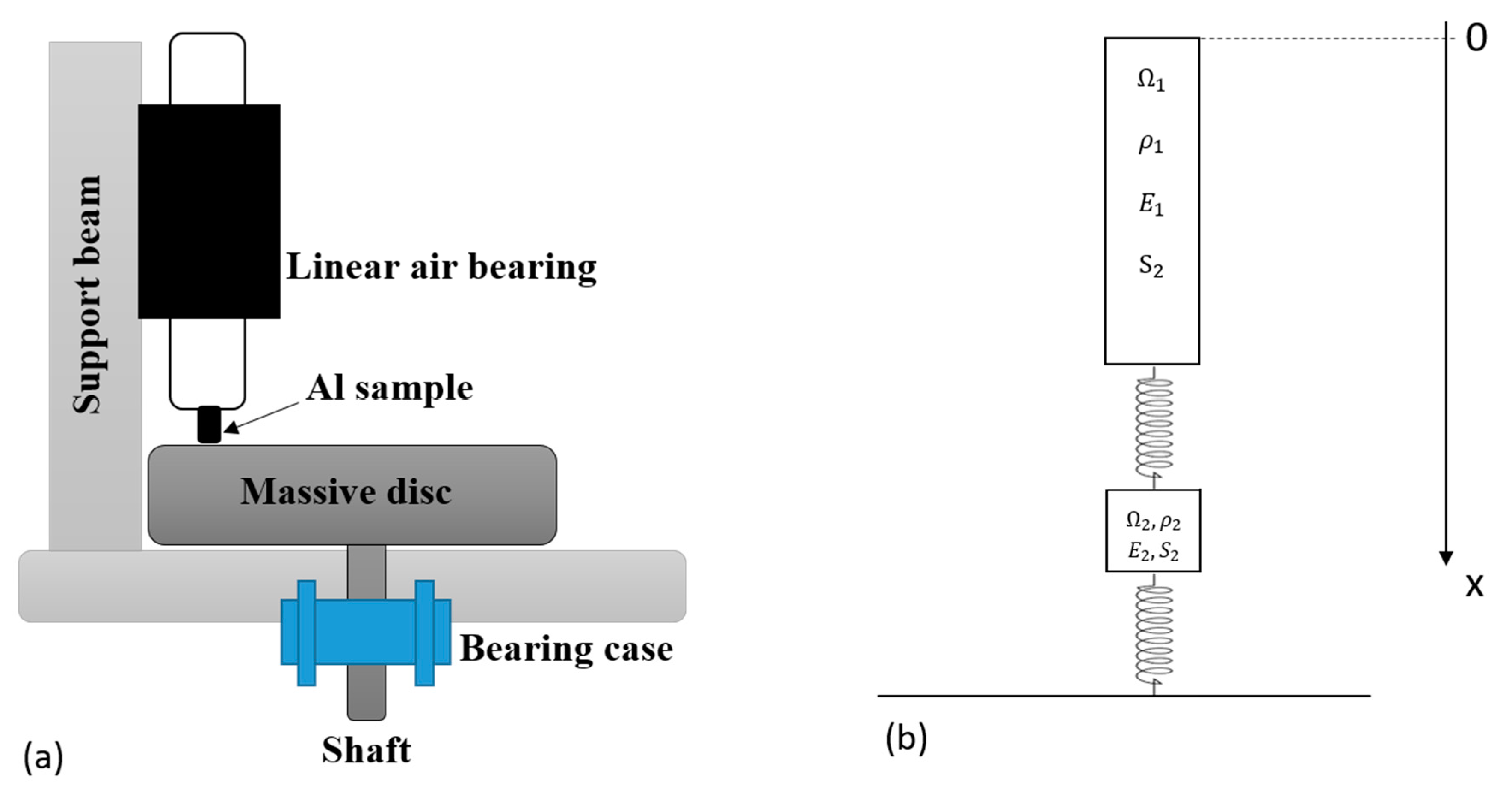
The nonlinear response of an experimental test bench (Figure 1) to an impulsive force is then modelled in a one-dimensional framework, including two rough contact interfaces with nonlinear contact stiffness.
The tested contact stiffness laws are first identified over a large contact pressure range, using both the experimental tests and results from the literature [15,18,28]. However, there is a lack, both experimentally and from the literature, of assessments of the stiffness trend within the lower pressure range (less than 0.14 MPa). By comparing the nonlinear time responses of the experimental system with the numerical results obtained by different stiffness–pressure curves, this gap is discussed.
The analysis was conducted in terms of the evolution of the amplitude of the fundamental and second harmonics and their frequencies, as a function of the force amplitude. In fact, due to the nonlinearity of the contact in compression, higher harmonics [26] appear in the spectrum of the vibrational response.
The numerical results derived from a specific nonlinear law, reconstructed from the available experimental data, are compared to other contact laws in the literature, in particular with respect to constant linear contact stiffness [29] and the power–law relation between stiffness and pressure [15].
In this article, the system remains in compression for all the configurations throughout the simulations. The “clapping” effect, which leads to a further strong nonlinearity [30] and denotes intermittent loss of contact at the interface, is not studied in this work.

2.2. Experimental Set-up

The set-up used for all the experimental measurements is presented in Figure 1. The system was designed to estimate the contact stiffness between two rough interfaces of different sample materials, within a range of average contact pressure up to 1 MPa, in both sticking and sliding conditions [18]. The system consists of a sample in contact with a massive steel disc and loaded by the dead weights on a guide bar, as shown in Figure 1.
The guide is maintained by an air bearing, to enable it to oscillate and not introduce further stiffness and friction in the vertical direction.
The tested sample consists of aluminium (Al). The material properties and surface roughness are presented in Table 1.
An impulsive-type force is applied by an instrumented impact hammer (Brüel and Kjær type 8202), while the dynamic response of the system is recorded by an accelerometer placed on top of the guide bar.
All tests presented in the paper are performed on the system, with the overall weight of the guide bar on top of the sample, generating a static equilibrium pressure σ 0 = 0.14   MPa .
Measurements of the force and acceleration of the system are recorded using the acquisition system (SIRIUS–DEWESOFT), based on DualCoreADC® technology with dual 24-bit delta-sigma analogue to digital converter (ADC). An anti-aliasing filter on each analogue channel achieves a 160 dB dynamic range in time and frequency domains with 200 kHz sampling rate per channel. Data are post-processed by Matlab.
We assume that there is no interface separation between the two contact surfaces during the tests. This assumption is supported by the numerical simulations for the levels of impulsive excitation used.

2.3. D Numerical Model

A one-dimensional numerical model of the experimental set-up was implemented (Figure 2) consisting of the guide bar Ω 1 of the experimental set-up and the tested aluminium sample Ω 2 , modelled by unidimensional deformable bodies.
Two contacting interfaces are considered: the first between the guide bar Ω 1 and the tested sample Ω 2 , and the second between the tested sample and the frame, considered as infinitely rigid in the model (tribometer disc). The model parameters are provided in Table 2. Note that, in reality, the cross-sections of the guide bar Ω 1 and aluminium sample Ω 2 are different. Numerically, an equivalent 1D-model with the same cross-section S2 is considered, corresponding to the contact surface S2.
For both interfaces, a nonlinear contact law is introduced. This law includes a nonlinear stiffness function of the contact pressure.
Once a force is applied to the top of the system, longitudinal waves propagate along the vertical x-axis and excite the longitudinal modes of the system, including the mass-spring mode, where the mass is the guide bar and the spring is due to the stiffness in series of the sample and the two contact interfaces.
The numerical modelling assumes the following hypotheses:
  • The dynamic of interest is in the vertical direction, i.e., the numerical model can be reduced to one dimension (1D) (Figure 2b);
  • The massive disc in the set-up can be considered as rigid within the frequency range of interest.
  • Throughout the analysis, the interface remains in contact. Thus, no dissipation occurs at the interface and damping at the contact is disregarded;
  • The impact of the hammer can be modelled by introducing the respective force F into the boundary conditions, measured at the tip of the instrumented hammer:
    σ / x = 0 = F S 2
    where σ / x = 0 is the stress at the upper side of the guide bar.
a.
Governing equations
In the absence of elastic wave, the system is assumed to be free at the upper part and subject only to its own weight. In a first static step, the equilibrium position of the system can be calculated.
For the longitudinal waves propagating along the x-direction (longitudinal), in both the guide bar and the aluminum sample, the equation of motion is the following
2 u t 2 c 2 2 u x 2 + h u t = g
where u (x,t) is the displacement in the x-direction at time t, from the non-deformed configuration, c is the wave velocity, g is the gravity acceleration, h is the viscosity factor and t denotes the time.
The viscosity factor h is constant in the model and was determined from the damping factor ξ = h 2 m ω 0 , where ω 0 is the angular frequency of interest. The damping factor value ξ = 0.035 was identified experimentally by logarithm decrement at the frequency of interest, which is the frequency of the corresponding mass-spring mode. In fact, the main mode of vibration, the focus of the analysis, is the response of the guide mass to the stiffness obtained by the bulk stiffness of the sample in series with the stiffness of the two contact interfaces (Figure 2).
The model is discretized in both time and space using the Euler scheme [31].
The unidimensional wave Equation (1) has been discretized using a second order centered finite difference (FD) scheme, explicit in time, as follows
u k m + 1 2 u k m + u k m 1 δ t 2 c 2   u k + 1 m 2 u k m + u k 1 m δ x 2 + h u k m + 1 u k m δ t   = g   ,   k ϵ [ 2 , n 1 1 ]   [ n 1 + 2 , n 1 + n 2 1 ]
where the subscript k indicates the node number and m indicates the time step number, with δ x and δ t corresponding, respectively, to the space and time discretisation steps. n 1 and n 2 are, respectively, the total number of nodes contained in solids Ω1 and Ω2. This second-order general scheme is conditionally stable under the classic Courant–Friedrichs–Lewy (CFL) condition:
c δ t δ x < 1
Equation (2) can be re-written to obtain the displacement at the next time step m + 1 for each internal node, as follows
u k m + 1 = u k m   ( 2 ( 1 α 1 ) + α 2 1 + α 2 ) + α 1 1 + α 2 ( u k + 1 m + u k 1 m ) + 1 1 + α 2 ( g d t 2 u k m 1 )
k ϵ [ 2 , n 1 1 ]   [ n 1 + 2 , n 1 + n 2 1 ]
where α 1 = c 2 δ t 2 δ x 2 and α 2 = h .   d t
At contact interfaces (at x = x C 1 between the two solids Ω1 and Ω2 and x = x C 2 between Ω2 and the frame), the contact stresses σ (x = x C 1 ,t) and σ (x = x C 2 ,t) has the following expression in compression
σ ( x C i , t ) = K ( σ ( x C i , t ) ) Δ u C i
where K denotes the nonlinear stiffness of the contact interface depending on the contact stress and Δ u C i the gap distance at interfaces. i indicates either the contact between the two solids Ω1 and Ω2 (i = 1) or the contact between Ω2 and the frame (i = 2).
In order to evaluate properly the solution at both contact interfaces ( σ ( x C i , t ) , K ( σ ( x C i , t ) ) and Δ u C i ), it is necessary to solve Equation (5), and thus apply an implicite scheme (finite difference), using the relation between the contact pressure and the gap distance extracted from the implemented nonlinear relation between the stiffness and the pressure, presented in what follows.
b.
Contact law
Contact between two interfaces is generally modelled by a relationship between the interfacial gap and the contact pressure. The contact laws can be extracted analytically from various statistical models of rough surfaces. Drinkwater [11] and Baltazar et al. [32] attempted to link the roughness topography to the contact stiffness, transmission/reflexion coefficients, measured ultrasonically, and frequency.
However, it is generally difficult to take into account all the detailed information about third body [33] features, i.e., local deformations and interactions within a real interface and roughness [34,35].
As an alternative approach, the desired function can be modelled as a nonlinear contact stiffness, with respect to the applied contact pressure. When two rough surfaces are pressed together, the stiffness K c per unit of area of the interface is given by the rate of change in nominal pressure σ with the average interfacial gap. Contact stiffness Kc can be determined in general from [9]
K c = σ u
where σ is the nominal contact pressure and u is the average interfacial gap.
In the literature, for higher contact pressures (greater than 0.14 MPa, which is the lowest value of pressure used for the experimental estimation of contact stiffness, see Table 2), contact stiffness is often assumed to follow a power law [15]. This latter model gives the relationshi between the contact stiffness and the applied pressure as follows
K c = σ u = C σ m
where C and m are positive constants.
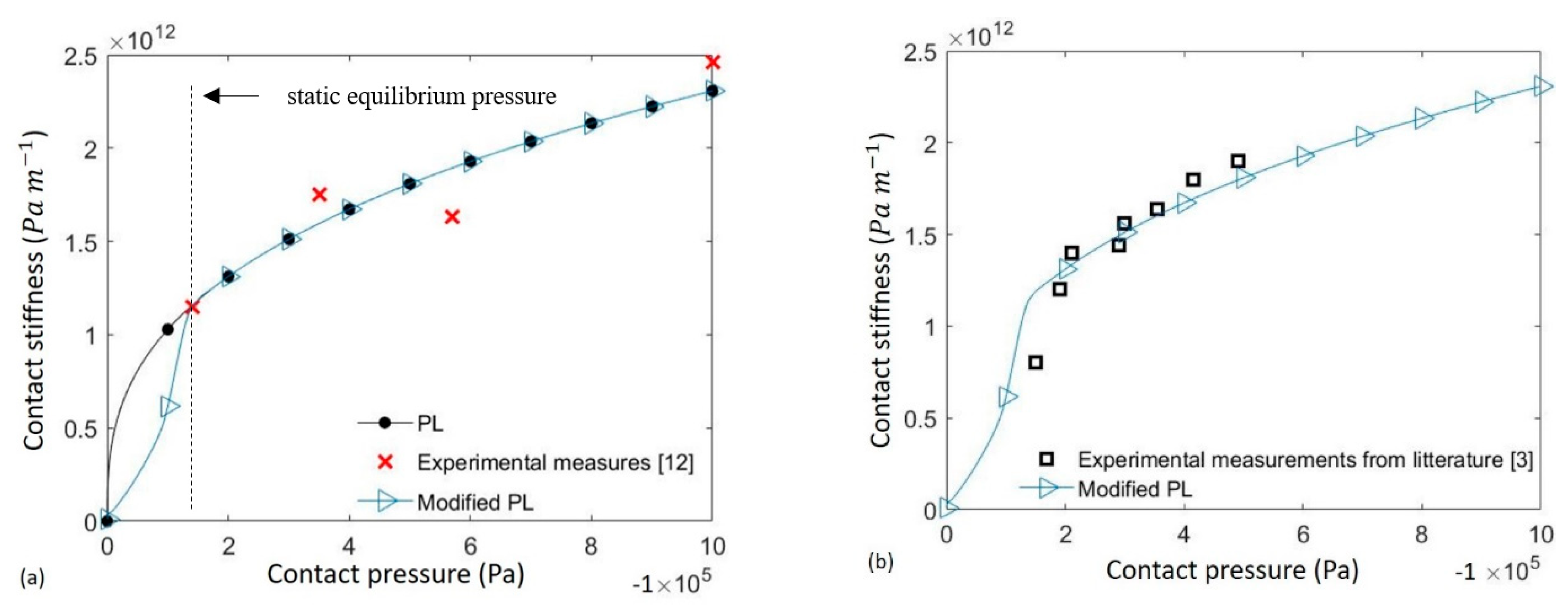
In this study, the contact stiffness of the tested samples was previously determined by experimental measurements, as reported in [18]. From preliminary dynamic tests at different contact pressures, the contact stiffness between 0.14 and 1 MPa could be estimated. Table 3 shows the results for contact stiffness as a function of the average contact pressure for the aluminum–aluminum interface, with a surface roughness of Ra = 1 μm.
The data highlight how the contact stiffness increases with the rise in the average contact pressure. The contact stiffness values range from 1.15 × 10¹² to 2.46 × 10¹² Pa/m when the contact pressure increases from 0.14 to 1 MPa.
Even if a contact interface is expected to show hysteresis, with a slightly different stiffness during loading and unloading phases, the authors considered this effect negligible, or at least not measurable. The complexity of an interface, including third body particles, chemical bounds and oxides, leads to the need for an overall approximation, which is here represented by the stiffness parameter. Of course, such approximation can have different implications, as a function of the wished phenomena to be investigated.
These experimental results are useful for defining the numerical contact stiffness within the tested range of contact pressures. Nevertheless, for implementing the contact law in the numerical simulations, it is necessary to define the stiffness for the whole pressure range [0; 1 MPa], in which the contact pressure will vary.
A first approximation within this pressure range was obtained by approximating the experimental measurements by a power law function, as in Equation (3). The least squares method allows a good agreement with the experimental data (Table 3), which are available from pressure 0.14 MPa. This agreement is obtained for C = 1.81 × 10¹⁰ Pa/m and m = 0.35. The power law (“PL” in Figure 3a) is thus defined to approximate the experimental points (Table 3).
While this power law has been built with consideration to the measurements and the literature dealing with higher pressures, the approximation of the trend at lower pressures is completely arbitrary. In order to model the contact stiffness trend for lower contact pressures, other experimental observations in the literature [6] have been exploited. These experimental results show the existence of an inflexion point for low-contact pressures (Figure 3b). From experimental results (Table 3) and the literature [6] it is then possible to propose a different overall contact stiffness trend, as a function of the contact pressure, including the inflection point between 0.14 and 0 MPa (“Modified PL” in Figure 3.
Finally, the stiffness laws, which will be investigated in the following, are:
  • The “PL” law, corresponding to the best approximation of experimental data (Table 3) by a power law.
  • The “Modified PL”, defined piecewise. It is equal to “PL” for pressures greater than 0.2 MPa, and for lower pressures it accounts for the inflexion point reported in [6].
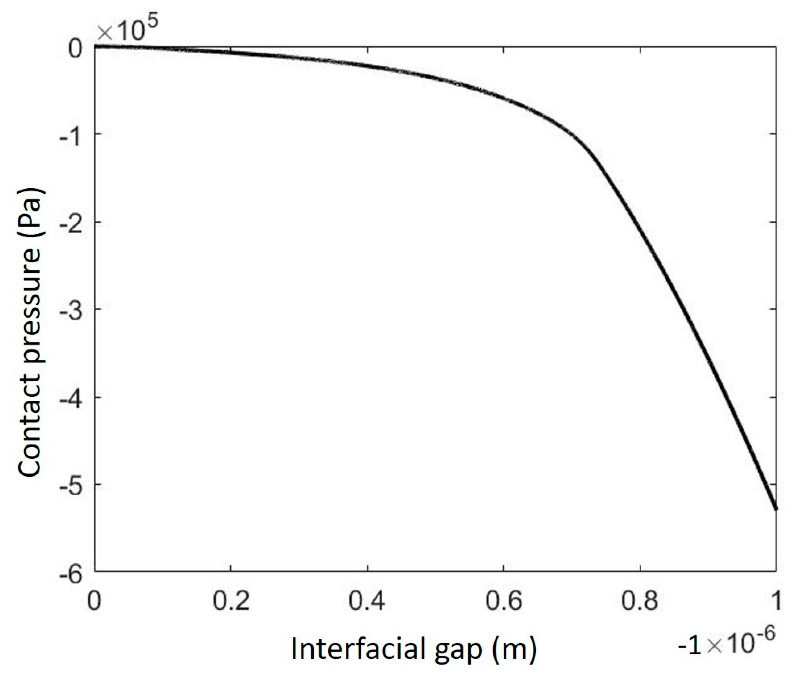
The relationship between the contact pressure and the interfacial gap can then be extracted from the implemented nonlinear relation between stiffness and pressure. For example, the results derived from the “Modified PL” are shown in Figure 4, highlighting the nonlinear response of the interface.
In the following, the experimental nonlinear response of the system to an impulsive excitation force will be compared with the nonlinear response obtained by the simulations with the different laws analysed. The comparison will allow for a discussion of the different laws considered to simulate the effective interface stiffness nonlinearity.

3. Experimental and Numerical Comparison

3.1. Dynamic Response of the Contact System

The aim of this section is to compare the numerical and experimental dynamic responses of the system (Figure 2), in time and frequency. For the sake of conciseness, the comparison of the time signals with the experiments is first reported only for the “Modified PL”; in the following section, the general results obtained by both laws will be compared with the experiments.
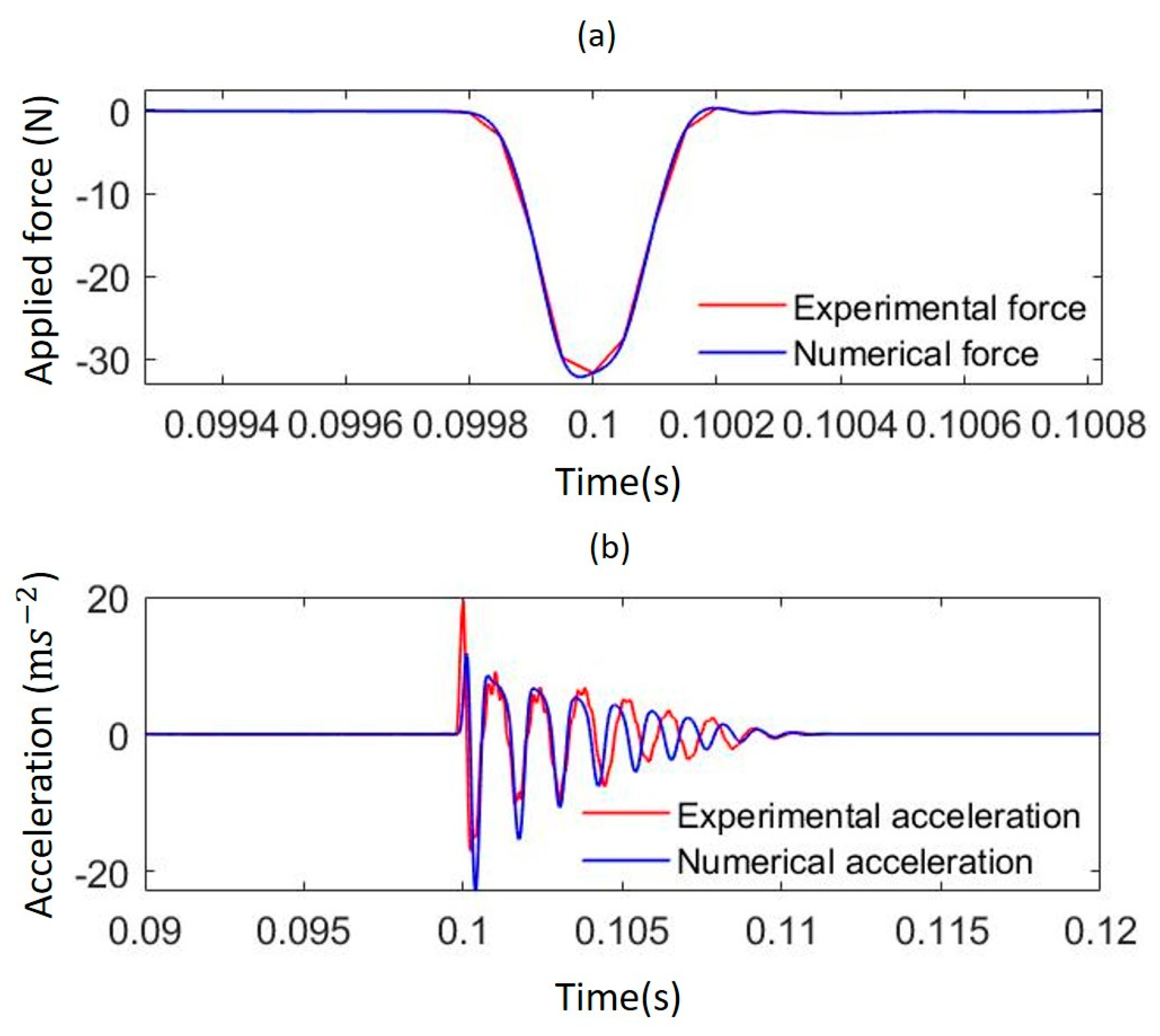
Experimentally, an impulsive force was applied to the upper side of the guide by an instrumented hammer (PCB Piezotronics-086C03). The case presented hereafter corresponds to an impulsive force of 32 N. The applied force and the acceleration are measured and shown in Figure 5a,b, respectively. For the numerical model, the measured experimental force has been interpolated (see Figure 5a) and introduced as a boundary condition in the numerical simulation. The model presented in Section 2, with the “Modified PL”, has been used to simulate the system response to the force.
Figure 5b shows the respective experimental and numerical accelerations, due to the dynamic system response.
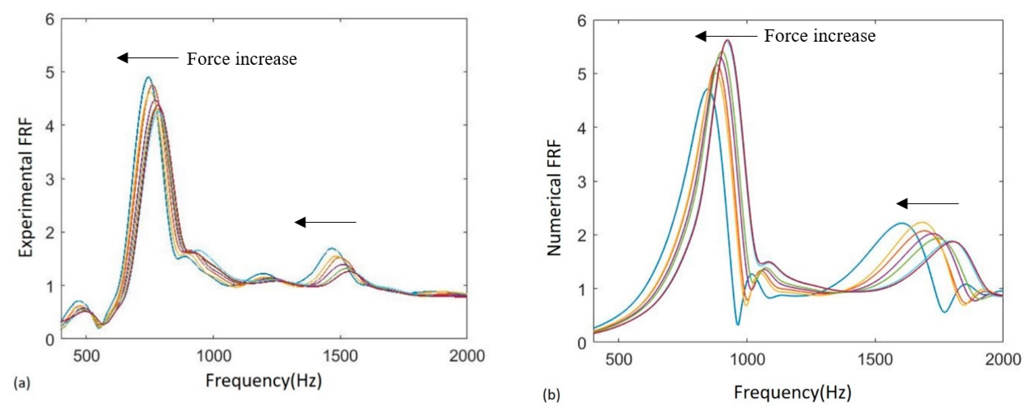
Experimental and numerical responses show good agreement in amplitude and time evolution. Figure 6 shows the Frequency Response Functions (FRF) [26], which provide the response of a system to an external excitation in the frequency domain. They are calculated from both numerical and experimental signals, to characterize the dynamics of the system. The numerical curves shown in Figure 6 correspond to the one obtained with a constant interface stiffness of 8.5 × 10¹¹ Pa/m (dashed line) and the one obtained with the “Modified PL” presented in Figure 3. The equivalent constant stiffness of 8.5 × 10¹¹ Pa/m was calculated to obtain the same frequency for the first harmonics of the “Modified PL”, to highlight its nonlinear contribution to the system response.
Only the fundamental (f~800 Hz) and second harmonics (f~1600 Hz) of the mass-spring mode are investigated here. Their results are well decoupled from the rest of the system dynamics.
The numerical spectra, obtained with either constant or nonlinear stiffness, show a peak around frequency f 1 = 800 Hz, corresponding to the fundamental frequency of the system. This is the natural frequency of the mass-spring mode, where the mass is the guide, while the spring is the series of the two interfaces and the sample stiffness (Figure 2). The comparison shows good agreement between the numerical and experimental results in terms of frequency and width of the peaks, i.e., damping. The amplitude of the fundamental is well simulated as well, with a percentage error less than 10%.
Unlike the spectra obtained with the constant stiffness, those based on nonlinear stiffness show a peak around frequency f 2 = 2 f 1 = 1600 Hz, which is also recovered experimentally. This peak represents the second harmonic and correlates with the experimental second harmonic.
The presence of the second harmonic in the spectra is due to the nonlinear nature of the contact stiffness. This is confirmed by the absence of this harmonic in the numerical results obtained with the constant contact stiffness (Figure 6 dashed line), and thus the occurrence of the second harmonic in experiments can be directly correlated with the nonlinearity of the interface stiffness.

3.2. Nonlinear Response of the Interface

In order to discuss the proposed trends of numerical contact stiffness and evaluate it by comparison with experiments, a spectrum analysis of the acceleration signals is reported in this section, as a function of the amplitude of the impulsive force. It is assumed that an increase in the force, and then in the system response, increases the nonlinear contribution of the interface to the system response.
A comparison of experimental and numerical FRFs, derived from the “Modified PL”, is carried out for different impulsive force amplitudes, ranging from 9 to 32 N (Figure 7).
When increasing the force amplitude, the overall average stiffness at the interface decreases, leading to a decrease in mode frequency (Figure 7). The nonlinearity of the interface stiffness is observable by the appearance of the second harmonic (frequency from 1400 to 1800 Hz, depending on the amplitude of the impulsive force) in the system response.
In the following, the numerical results obtained with the different contact laws, as presented in Figure 3, are compared with the experimental results in terms of the magnitude of the fundamental and second harmonics, as well as in terms of the frequency of the fundamental, as a function of the applied force.
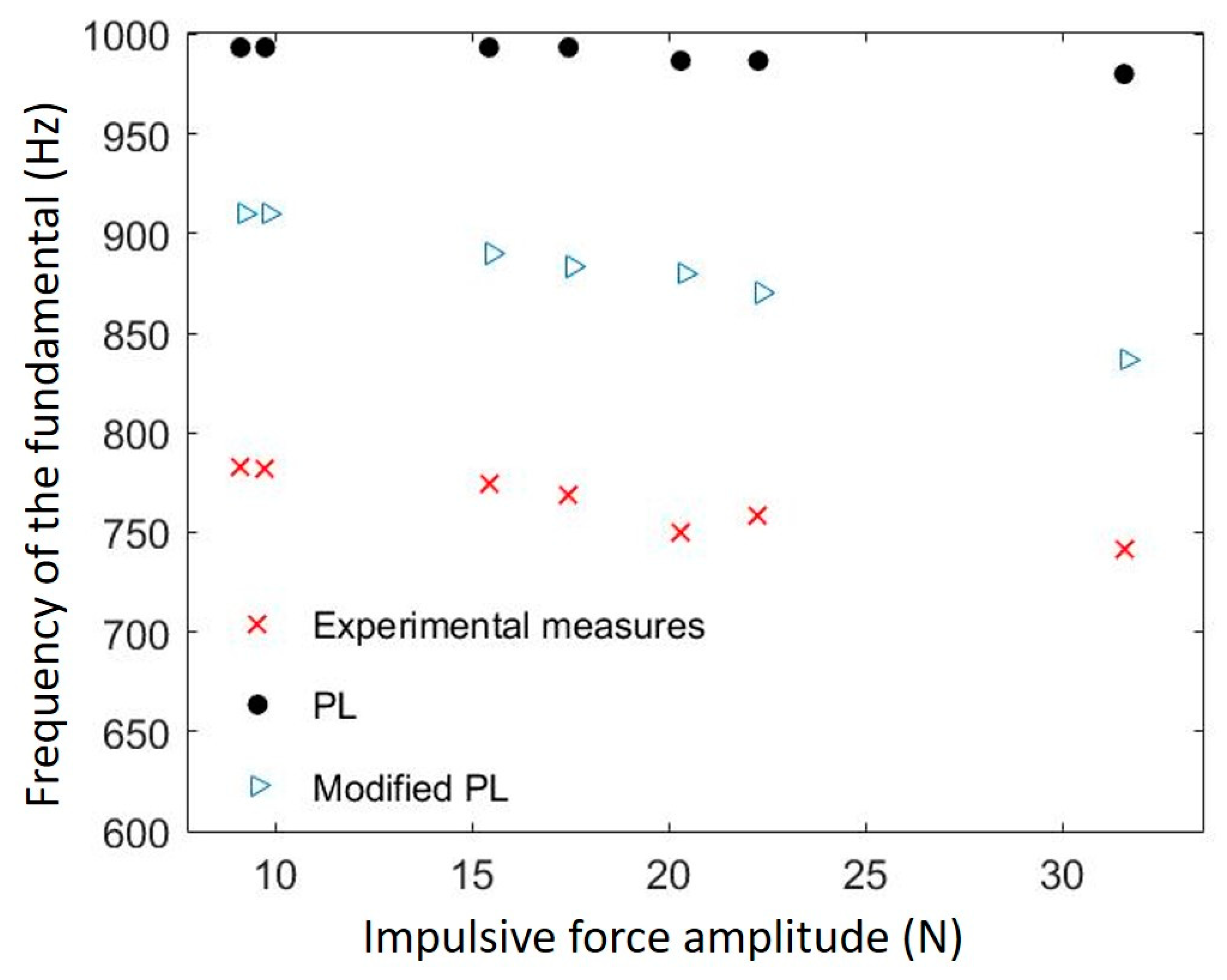
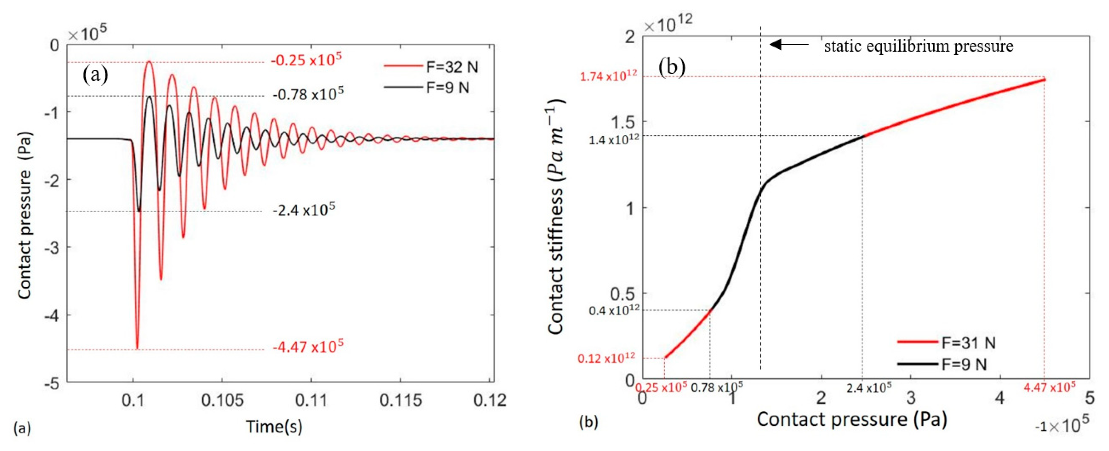
Figure 8 shows the frequency evolution of the fundamental harmonic as a function of the amplitude of the applied force. As observed in the experimental results, a decrease in frequency was obtained in the numerical simulations with the implemented “Modified PL”. This decrease is due to the decrease in the effective average stiffness when the oscillation at the contact increases. Experimentally, this trend has already been observed in [18]. It is worth mentioning that the decrease in frequency when the force amplitude increases (Figure 8) is also recovered by the “PL”, but with a lower slope. A slight decrease in frequency (2%) can be observed in Figure 8 for the “PL”, which is lower than for the experimental one (5%). Conversely, the “Modified PL” introduces a greater decrease in terms of stiffness, particularly for low contact pressures, as shown in Figure 9.
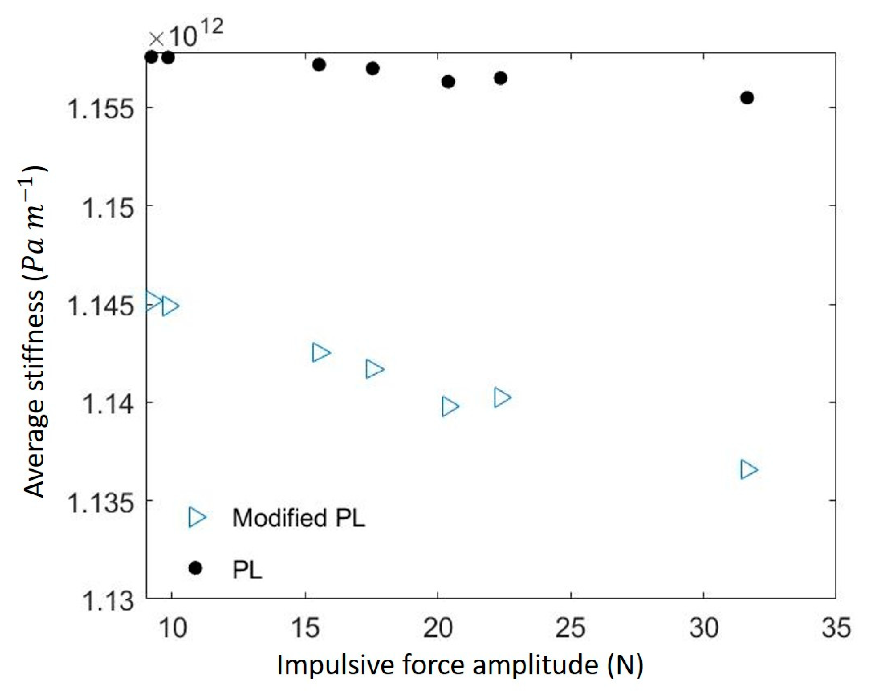
It should also be noted that, while the trend of the frequency is correctly simulated by the proposed laws, an error in the absolute value of the frequency, around 13%, is observed. This is due to the non-infinite stiffness of the counterpart (tribometer disc), unlike the infinite stiffness in the simulation, which implies a lower experimental frequency. Thanks to the numerical results, the decrease in the frequency of the fundamental can be shown to be related to a decrease in the mean value of contact stiffness, with the increase in the applied force
K a v r = 1 T t = 0 T | K c ( t ) |
where K c is the stiffness and T is the time of simulation.
In order to highlight the difference in average stiffness according to the force amplitude, Figure 9a shows the system response to two different force amplitudes, using the “Modified PL”. An applied force of 9 N generates a maximum contact pressure of −0.078 MPa, resulting in an average contact stiffness of 0.4 × 10¹² Pa/m, while a force of 32 N generates a maximum contact pressure of −0.025 MPa and an average contact stiffness of 0.12 × 10¹² Pa/m.
Figure 10 shows the evolution of average contact stiffness Kavr for the “Modified PL” and the “PL”. It confirms the decrease in average stiffness when the applied force is increased, which explains the decrease in frequency (Figure 7).
Figure 11 shows the evolution of the amplitude of the fundamental, as a function of the applied force, for the different contact laws.
Considering the mean value of the fundamental harmonic over the considered range of pressure, the “Modified PL” produces amplitudes closer to the experimental ones for this set of experimental measurements.
Nevertheless, as shown in Figure 11, for both of the implemented laws, the slight experimental increase in the amplitude of the fundamental (A1), with respect to the force amplitude, is not retrieved numerically. As mentioned above, this could be explained by the different boundary conditions between the numerical and experimental systems. In fact, the experimental set-up is not completely rigid, due to the deformability of the bench components (disc, shaft, bearings, etc.). Despite using a massive disc to isolate the dynamics of the investigated system (air guide and samples in contact) from the rest of the set-up as much as possible, a slight error is introduced by the residual flexibility of the system.
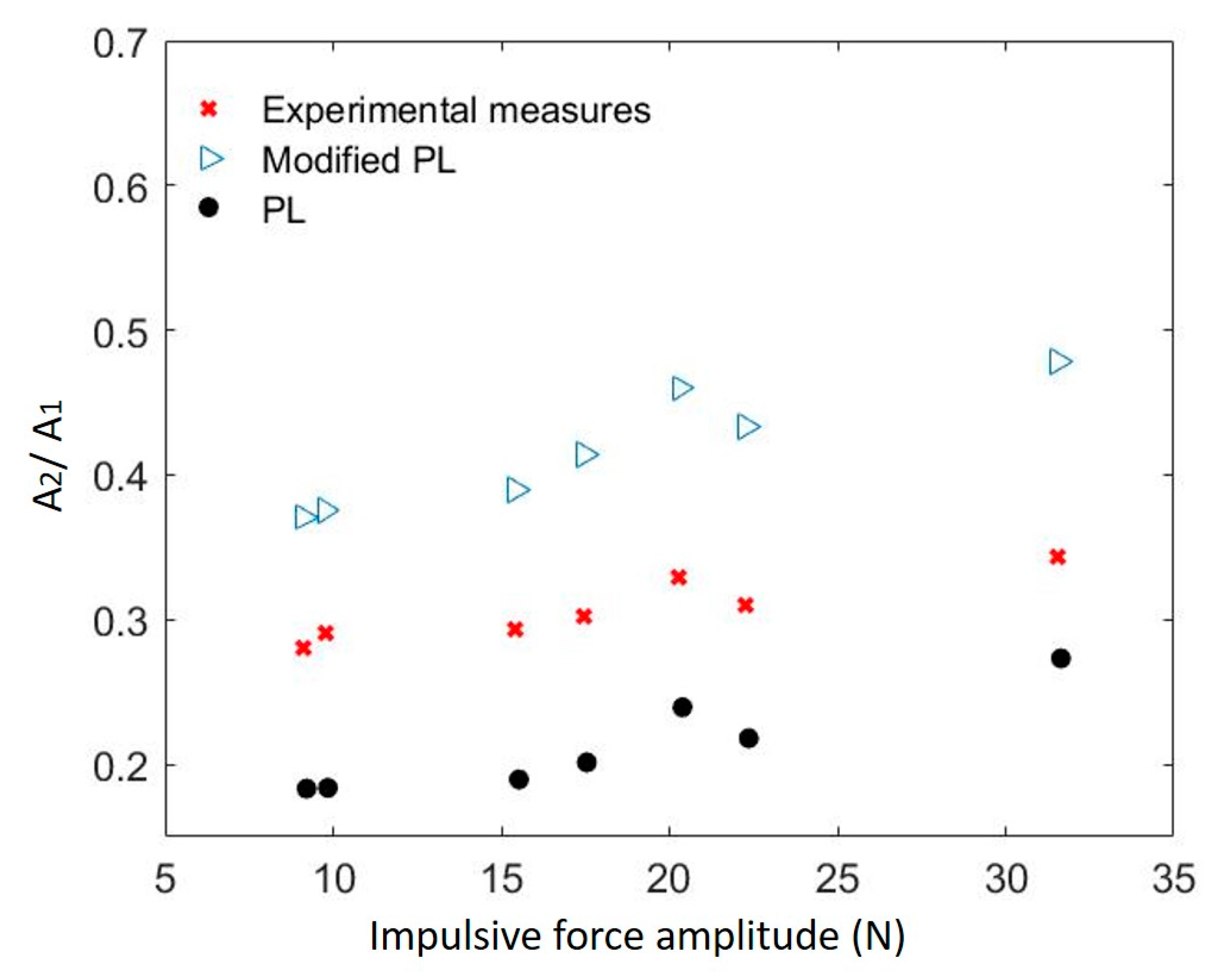
Finally, Figure 12 shows the ratio (A2/A1) of the amplitudes of the second harmonic (A2) to the fundamental (A1), obtained both experimentally and numerically, for both contact laws. It can be noted that the amplitude of the second harmonic is normalized by the amplitude of the fundamental, which is dependent on the energy introduced by the external force at this frequency, in order to highlight the nonlinear contribution originated by the contact interface.
The trends of the A2/A1 ratio, calculated for all the tested contact laws, are similar to the experimental trend. In general, an increase in the amplitude of the applied force (x axis in Figure 12), and consequently a higher amplitude of the system vibrational response, generates a greater nonlinear contribution, both numerically and experimentally. In fact, a larger oscillation of the contact pressure (especially within the low-contact pressure range, absolute value [0; 0.14 MPa]) generates a more nonlinear response by the system, which leads to a higher distortion of the signals and then a higher second harmonic contribution. The higher amplitude observed for the second harmonic of the “Modified PL” is due to the higher nonlinearity of the stiffness around the equilibrium position, with respect to the “PL”.
The overall comparison, based on the analysis reported above, highlights the fact that the contact interface response depends heavily on the stiffness trend at lower pressures (less than 1 MPa). This stiffness trend at lower pressures introduced by the “Modified PL” increases the nonlinearity of the response (second harmonic amplitude) and decreases the average stiffness, i.e., the frequency of the main harmonics.
These results demonstrate that the stiffness trend at lower pressures plays a vital role and should be clearly identified, as it has a huge effect on the nonlinear response of mechanical systems with contact interfaces.

4. Conclusions

The nonlinear normal stiffness of contact interfaces, due to surface roughness, is a topic of major interest in several areas of application. A consequence of such nonlinearity is the appearance of second harmonic terms, either in acoustic wave propagation through the interface or in the dynamic vibrational response of systems with contact interfaces.
While contact stiffness nonlinearity at higher pressures has been widely discussed in the literature, and generally approximated by a power law, the contact stiffness trend at lower pressures has not been clearly identified. In this paper, a classical power law, fitted from experimental data at high contact pressures, is compared with a modified power law implementing an inflection point at lower pressures, where experimental data are not available. The stiffness-pressure trend within the higher contact pressure range was approximated from experimental measurements performed on a dedicated test bench. Within the lower contact pressure range, data from the literature were used to assume the different possible trends.
The nonlinear response of the system, obtained experimentally when exciting a dedicated system with an impulsive force, was analysed and compared with the nonlinear response of the numerical model that was developed, with the contact interface modelled by the different contact laws.
From the numerical simulations it was possible to identify the effect of the contact nonlinearity on the dynamic response of the system. The decrease in the average contact stiffness with the increase in the impulsive force explains the appearance of the second harmonics and the decrease in the fundamental frequency. In addition, the amplitude of the second harmonic was simulated and explained by the stiffness trend at the contact interface during the system oscillations.
In the nonlinear system response, the key role of the contact stiffness trend within the lower pressure range is highlighted, demonstrating the need to identify such parameters with dedicated experimental tests. Nonlinear contact laws and their effect on the dynamics of a system ought to be further investigated by implementing the contact laws considered here in finite element codes, in order to consider more realistic structures and interfaces.

Author Contributions

Methodology, D.N., A.M., L.B. and F.M.; visualization, D.N.; investigation, D.N. and D.T.; data curation, D.N. and D.T.; writing—original draft preparation, D.N.; writing—review and editing, A.M., L.B. and F.M.; validation, A.M., L.B. and F.M.; supervision, A.M. and F.M. All authors have read and agreed to the published version of the manuscript.

Funding

This research received no external funding.

Conflicts of Interest

The authors declare no conflict of interest.

References

  1. Armstrong-Hélouvry, B. Control of Machines with Friction. J. Tribol. 1992, 114, 637. [Google Scholar] [CrossRef] [Green Version]
  2. Koc, M.; Eray, T.; Sümer, B.; Cerci, N. An active force controlled laparoscopic grasper by using a smart material actuation. Tribol. Int. 2016, 100, 317–327. [Google Scholar] [CrossRef]
  3. Bhushan, B. Tribology and Mechanics of Magnetic Storage Devices; Springer Science & Business Media: New York, NY, USA, 2012. [Google Scholar]
  4. Türkmen, D.; Koc, I.M.; Sümer, B. Adhesive Pillar Based Air Levitation System for Contactless Manipulation of Fine Objects. Procedia Eng. 2015, 120, 1124–1127. [Google Scholar] [CrossRef] [Green Version]
  5. Tonazzi, D.; Massi, F.; Baillet, L.; Brunetti, J.; Berthier, Y. Interaction between contact behaviour and vibrational response for dry contact system. Mech. Syst. Signal Process. 2018, 110, 110–121. [Google Scholar] [CrossRef]
  6. Shi, X.; Polycarpou, A. Measurement and modeling of normal contact stiffness and contact damping at the meso scale. J. Viration Acoust. 2005, 127, 52–60. [Google Scholar] [CrossRef]
  7. Johnson, K.L. Contact Mechanics; Cambridge University Press: Cambridge, UK, 1985. [Google Scholar]
  8. Greenwood, J.A.; Williamson, J.P.B. Contact of nominally flat surfaces. Proc. R. Soc. Lond. 1966, 295, 300–319. [Google Scholar]
  9. Richardson, J.M. Harmonic Generation at an Unbonded Interface: I.Planar Interface Between Semi-Infinite Elastic Media. Int. J. Eng. Sci. 1979, 17, 73–85. [Google Scholar] [CrossRef]
  10. Rudenko, V. Nonlinear Acoustic Properties of a Rough Surface Contact and Acoustodiagnostics of a Roughness Height Distribution. Acoust. Phys. 1994, 40, 593–596. [Google Scholar]
  11. Drinkwater, B.W.; Dwyer-Joyce, R.S.; Cawley, P. A Study of the Interaction Between Ultrasound and a Partially Contacting Solid-Solid Interface. Proc. R. Soc. Lond. 1996, 452, 2613–2628. [Google Scholar]
  12. Polycarpou, A.; Soom, A. Boundary and Mixed Friction in the Presence of Dynamic Normal Loads. I. System Model. J. Tribol. 1995, 117, 261–266. [Google Scholar] [CrossRef]
  13. Song, Y.; Hartwigsen, C.; McFarland, D.; Vakakis, A.; Bergman, L. Simulation of dynamics of beam structures with Bolted Joints using adjusted Iwan beam elements. J. Sound Vib. 2004, 273, 249–276. [Google Scholar] [CrossRef]
  14. Jin, J.; Johnson, P.; Shokouhi, P. An integrated analytical and experimental study of contact acoustic nonlinearity at rough interfaces of fatigue cracks. J. Mech. Phys. Solids 2020, 135, 103769. [Google Scholar] [CrossRef]
  15. Biwa, S.; Nakajima, S.; Ohno, N. On the acoustic nonlinearity of solid-solid contact with pressure-dependent interface stiffness. J. Appl. Mech. 2004, 71, 508–515. [Google Scholar] [CrossRef]
  16. Aleshin, V.V.; Papangelo, A. Friction-induced energy losses in mechanical contacts subject to random vibrations. Int. J. Solids Struct. 2020, 190, 148–155. [Google Scholar] [CrossRef]
  17. Pastewka, L.; Prodanov, N.; Lorenz, B.; Müser, M.H.; Robbins, M.O.; Persson, B.N. Finite-size scaling in the interfacial stiffness of rough elastic contacts. Phys. Rev. E. 2013, 87, 062809. [Google Scholar] [CrossRef] [PubMed] [Green Version]
  18. Tonazzi, D.; Massi, F.; Salipante, M.; Berthier, Y. Estimation of the normal contact stiffness for frictional interface in sticking and sliding condition. Lubricants 2019, 7, 56. [Google Scholar] [CrossRef] [Green Version]
  19. Kendall, K.; Tabor, D. An ultrasonic study of the area of contact between stationary and sliding surfaces. Proc. R. Soc. Lond. 1971, 323, 321–340. [Google Scholar]
  20. Aleshin, V.; Matar, O.B.; van den Abeele, K. Method of memory diagrams for mechanical frictional contacts subject to arbitrary 2D loading. Int. J. Solids Struct. 2015, 60, 84–95. [Google Scholar] [CrossRef]
  21. Aleshin, V.; Delrue, S.; Trifonov, A.; Matar, O.B.; van den Abeele, K. Two dimensional modeling of elastic wave propagation in solidscontaining cracks with rough surfaces and friction—Part I: Theoretical Background. Ultrasonics 2018, 82, 11–18. [Google Scholar] [CrossRef]
  22. Aleshin, V.; Delrue, S.; Trifonov, A.; Matar, O.B.; van den Abeele, K. Two dimensional modeling of elastic wave propagation in solidscontaining cracks with rough surfaces and friction—Part II: Numerical implementation. Ultrasonics 2018, 82, 19–30. [Google Scholar] [CrossRef]
  23. Biwa, S. Second-Harmonic Generation at Contacting Interfaces. In Nonlinear Ultrasonic and Vibro-Acoustical Techniques for Nondestructive Evaluation; Springer: Cham, Germany, 2019; pp. 263–299. [Google Scholar]
  24. Saidoun; Meziane, A.; Rénier, M.; Bacon, C.; Zhang, F.; Walaszek, H. Influence of contact interface morphology on the nonlinear interaction between a longitudinal wave and a contact interface with friction: A numerical study, submitted to wave motion. Article submitted for publication.
  25. Van den Abeele, K.A.; Carmeliet, J.; Cate, J.A.T.; Johnson, P.A. Nonlinear elastic wave spectroscopy (NEWS) techniques to discern material damage, Part II: Single-mode nonlinear resonance acoustic spectroscopy. J. Res. Nondestruct. Eval. 2000, 12, 31–42. [Google Scholar] [CrossRef]
  26. Gonzalez-Valadez, M.; Baltazar, A.; Dwyer-Joyce, R. Study of interfacial stiffness ratio of a rough surface in contact using a spring model. Wear 2010, 268, 373–379. [Google Scholar] [CrossRef] [Green Version]
  27. Teufelsbauer, H.; Wang, Y.; Chiou, M.; Wu, W. Flow–obstacle interaction in rapid granular avalanches: DEM simulation and comparison with experiment. Granul. Matter 2009, 11, 209–220. [Google Scholar] [CrossRef]
  28. Blanloeuil, P.; Croxford, A.J.; Meziane, A. Numerical and experimental study of the nonlinear interaction between a shear wave and a frictional interface. J. Acoust. Soc. Am. 2014, 135, 1709–1716. [Google Scholar] [CrossRef]
  29. Bossy, M.; Gobet, E.; Talay, D. A symmetrized Euler scheme for an efficient approximation of reflected diffusions. J. Appl. Probab. 2004, 41, 877–889. [Google Scholar] [CrossRef] [Green Version]
  30. Baltazar, A.; Rokhlin, S.I.; Pecorari, C. On the Relationship Between Ultrasonic and Micromechanical Properties of Contacting Rough Surfaces. J. Mech. Phys. Solids 2002, 50, 1397–1416. [Google Scholar] [CrossRef]
  31. Massi, F.; Berthier, Y. Contact surface topography and system dynamics of brake squeal. Wear 2008, 265, 1784–1792. [Google Scholar] [CrossRef] [Green Version]
  32. Krolikowski, J.; Szczepek, J. Prediction of Contact Parameters using Ultrasonic Method. Wear 1991, 148, 181–195. [Google Scholar] [CrossRef]
  33. Asma, F.; Bouazzouni, A. Finite element model updating using FRF measurements. Shock Vib. 2005, 12, 377–388. [Google Scholar] [CrossRef]
  34. Ciavarella, M.; Papangelo, A. On the sensitivity of adhesion between rough surfaces to asperity height distribution. Phys. Mesomech. 2018, 21, 59–66. [Google Scholar] [CrossRef]
  35. Papangelo, A.; Hoffmann, N.; Ciavarella, M. Load-separation curves for the contact of self-affine rough surfaces. Sci. Rep. 2017, 7, 6900. [Google Scholar]
Figure 1. Experimental set-up.
Lubricants 08 00073 g001
Figure 2. Diagram (a) and numerical model (b) of the set-up for contact stiffness experiments.
Lubricants 08 00073 g002
Figure 3. Normal contact stiffness as a function of contact pressure in compression conditions. (a) Experimental results (red cross); Modified PL (blue triangle); PL (black circle). (b) Modified PL (blue triangle) and experimental data from the literature [6] (black square)
Lubricants 08 00073 g003
Figure 4. The corresponding contact pressure-interfacial gap trend for the ‘Modified PL’.
Lubricants 08 00073 g004
Figure 5. (a) Force signals over time, for a single force; (b) Acceleration signals over time obtained with ‘Modified PL’. Test performed with average contact force 32 N.
Lubricants 08 00073 g005
Figure 6. FRFs of the system (receptance, displacement/force). Numerical with nonlinear stiffness, numerical with constant stiffness with Kc = 8.5 × 10¹¹ Pa/m and experimental. Test performed with average contact force 32 N.
Lubricants 08 00073 g006
Figure 7. Frequency response functions (FRFs) of the system (receptance, displacement/force). (a) Experimental frequency response; (b) Numerical frequency response plotted with “Modified PL”. Test performed with average contact force ranging from 9 to 32 N.
Lubricants 08 00073 g007
Figure 8. Frequency of the fundamental, as a function of the force amplitude [N]. Experimental measurements (red cross), PL (black circle) and Modified PL (blue triangle).
Lubricants 08 00073 g008
Figure 9. Numerical results for maximum force F = 32 N (red) and minimum force F = 9 N (black). (a) Numerical contact pressure as a function of time; (b) Numerical stiffness as a function of contact pressure. Test performed on aluminium with Modified PL.
Lubricants 08 00073 g009
Figure 10. Average contact stiffness as a function of the applied forces. The test performed with average contact force ranging from 9 to 32 N, with Modified PL (blue triangle) and PL (black circle).
Lubricants 08 00073 g010
Figure 11. Magnitude of the FRF of the fundamental A1, as a function of the force amplitude. Comparison of the contact laws. Experimental measurements (red cross), Modified PL (blue triangle), and PL (black circle).
Lubricants 08 00073 g011
Figure 12. Ratio of magnitudes of the FRF of the second harmonic (A2) to fundamental (A1), as a function of the force amplitude. Experimental measurements (red cross), Modified PL (blue triangle) and PL (black circle).
Lubricants 08 00073 g012
Table 1. The tested aluminium sample.
Individual Sample ParametersInterface Parameter
Length
(m)
Contacting surface ( m 2 )Young modulus (GPa)Density (kg m 3 )Roughness (µm)
Ra
0.0151.15 × 10−47127101
Table 2. Geometry and material parameters of Ω 1 and Ω 2 in the numerical model.
Length L (m)Mass m (Kg)Young’s Modulus E (GPa) Density   ( kg m 3 ) Contacting   Surface   S 2   ( m 2 )
Guide bar ( 1 )0.2291.617127101.15 × 10−4
Sample ( 2 )0.0150.004677127101.15 × 10−4
Table 3. Normal contact stiffness as a function of the average contact pressure in sticking condition [15].
Aluminium Ra = 1 μm
Contact pressure [MPa]P = 0.14P = 0.35P = 0.57P = 1
Kc [Pa/m]1.15 × 10121.75 × 10121.63 × 10122.46 × 1012