1. Introduction
A cam follower is a mechanism in which the rotational motion (of the cam) is converted to an oscillating or reciprocating follower motion. This mechanism is simple and reliable which makes it used widely in the timing of many machines especially in internal combustion engines. The dynamics of the follower depend on the selected cam profile and its rotational speed in addition to the type of the follower itself. So that, the cam profile and the follower type are chosen according to the desired performance and requirements of the machines. In addition to their use in timing in the internal combustion engines, cams are also used in printing machines, packaging machines, and paper cutting machines, etc.
There are many types of cams and followers depending on their applications. The cams are mainly classified into disk cam and cylindrical cam while the followers have more diversity; in some cases they are classified according to their motion which are either reciprocating or oscillatory. In other cases, the followers are classified according to the surface in contact with the cam, such as knife edge, flat face, spherical face, and roller followers. More details about the cam-follower mechanism can be seen in [
1].
The cam follower is considered as higher pair mechanism; in higher pair, the type of contact between the elements are either line or point contact, while in the lower pair, surface contact occurs. The point and line contact in the higher pair mechanism are considered non-conformal contact. Other typical examples of this type of contact are those between gears teeth and also between the ball and the inner race of the bearings. In contrast to the conformal contact, such as the contact between the journal and the bearing, a significant deformation takes place at the contacted surfaces. So that, during the operation of the cam-follower mechanism and with existence of lubrication fluid, elastohydrodynamic lubrication (EHL) occurs. This type of lubrication for a cam with a flat-faced follower is studied in detail in this paper.
The EHL contact problems are solved by considering the contact either as a 2D or 3D problem. These are normally called line and point contact solution respectively. The 2D case can be used when the geometry along one of the two dimensions in contact does not change (the depth of the cam, for example). For problems where the geometry varies along the two dimensions in contact (modification of the cam depth as an example), the 3D EHL (point) model is required.
The lubrication of machines is a vital matter for designers and maintenance engineers. The main aims of the lubrication are to reduce the wear at the contact of the machine elements and reduce the lost frictional power during operation. During the last few decades, the amount of fuel consumption of machines has become a significant parameter. This issue was raised first to reduce the cost of operation of the machines, and second to minimize the pollution caused by the exhaust gases which became a big environmental problem. The lubrication of cams was studied earlier by Dyson and Naylor [
2] by focusing on tappet distresses which are mainly scuffing and polishing. They believed that the occurrence of these problems is controlled by the temperature in the contact region and their study was based on that. Muller [
3] studied the lubrication of the cam and tappet experimentally and theoretically by considering the geometry of the cams and the lubrication performance. In this study, it was concluded that the consideration of the oil film in the contact zone is the important factor for the tribological design. Dyson [
4] considered the Hertzian stress and lubricant film thickness over the cam cycle as the subjects that should be compromised in selecting the design parameters of cam-follower mechanism. The load at the contact zone is one of the factors that control the elastohydrodynamic lubrication. It is usually complicated to evaluate the load accurately along the cam cycle. Accordingly, measuring the load experimentally may be the choice; this was carried out by Bair et al. [
5]. A piezo-electric force transducer was fitted to the follower for measuring the force in three independent directions which allowed for measuring the friction force in addition to the load. Ball [
6] made a comprehensive tribological study on the automotive cams by using analytical methods for evaluating important parameters of lubrication. Tylor [
7] presented a lubrication analysis and an important review on the previous work on the lubrication of valve train (which is involving cam-follower mechanism).
The transient elastohydrodynamic analyses were also investigated by Kushwaha [
8] and Teodorescu et al. [
9]. Furthermore, Teodorescu et al. [
10] used an integrated tribological analysis within a multi- physics approach in piston and valve train systems. Nguyen and Kim [
11] described a synthesis method of designing flexible cam profiles by using smoothing spline curves.
Vela et al. [
12] studied cam-follower contact experimentally using existing apparatus which were used for investigation of non-conformal lubricated contact based on the optical interference method. The experimental tests confirmed the possibility of using this method in cam-follower contact. Wang et al. [
13] investigated the elastohydrodynamic lubrication of an eccentric-tappet pair in terms of the surface waviness wave length and eccentricity, the results showed that the waviness has a significant fluctuation on the oil film characteristics. An experimental study on a circular eccentric cam and follower was carried out by Ciulli [
14] using different eccentricities and surface roughness which gave encouraging points about the apparatus used. Wu et al. [
15] presented a thermal elastohydrodynamic study on a cam tappet pair assuming smooth contact. They made a comparison between thermal and isothermal analysis, the last gave an overestimation of the film thickness at some angular positions of the cam. The results also show significant variations of the oil film pressure and thickness at different selected angular positions over the cam.
Shirzadegan et al. [
16] used a finite length line EHL model for the simulation of contacts between cam and roller follower. In their study, systematic analyses were presented for the effects of roller crowning and edge geometries in additional to lubricant rheology. More recently, Alakhramsing et al. [
17,
18,
19] investigated in detail the contact problem of the cam-follower mechanism in which friction and mixed EHL analyses were considered.
Alakhramsing et al. [
17] for example, considered different roller axial profiles in order to study their effects on crucial performance indicators around the nose region. It was found that minimum film thickness and maximum pressure values can be improved significantly, however, at the cost of higher power losses. One of their important conclusions was that a suitable optimization routine is required to get an optimum combination between maximum pressure, minimum film thickness and friction losses.
The manufacturers of mechanical parts that transmitted power (or motion) rely on adding some edge relief (called chamfer) on the contacted edges rather than the modification of the whole profile due to manufacture considerations. This modification, if it is performed adequately, reduces the possibility of edge contact. Edge contact raises the contact stresses which are consequently shortening the life of the cam-follower system. Therefore, the point contact model is required to solve problems involving such modification. This paper deals with the cam-follower contact as an EHL point contact problem by introducing an axial modification of the cam depth where a non-Newtonian oil behavior is considered for the analyses. A detailed investigation is presented in this paper about the effects of chamfer on the levels of film thickness, pressure distribution and surface deformation. Consequently, a wide range of chamfer height and the start point of modification in the axial direction are also investigated at different positions in the mechanism operating cycle.
2. Cam and Follower Kinematics and Loading
As mentioned previously, a cam with a flat-face follower is studied in this paper which is shown in the schematic diagram of
Figure 1. In order to study the EHL contact problem at the cam-follower mechanism, the geometry and the velocity of the contacting surfaces in addition to the load should be determined at the instant under investigation. These variables depend on the profile of the cam, its rotational speed and the specification of the follower. To avoid dynamic problems in the cam-follower mechanism, the cam profile should be designed carefully for achieving smooth velocity, acceleration and jerk during operation.
The cam and follower specification, and the conditions of operation used in this study are similar to that used in [
6]. The cam profile is characterized by a four polynomial functions representing the follower lift
Lf for a variable cam angle
φ as following
where
YR = the height of the ramp;
Lfmax = the maximum lift;
= the cam half period;
are parameters and may be varied to achieve the required cam characteristics.
The relative velocity of points on the cam and the follower that are adjacent to the contact point at any angular position are given in the following forms:
For the cam,
and for the follower,
where
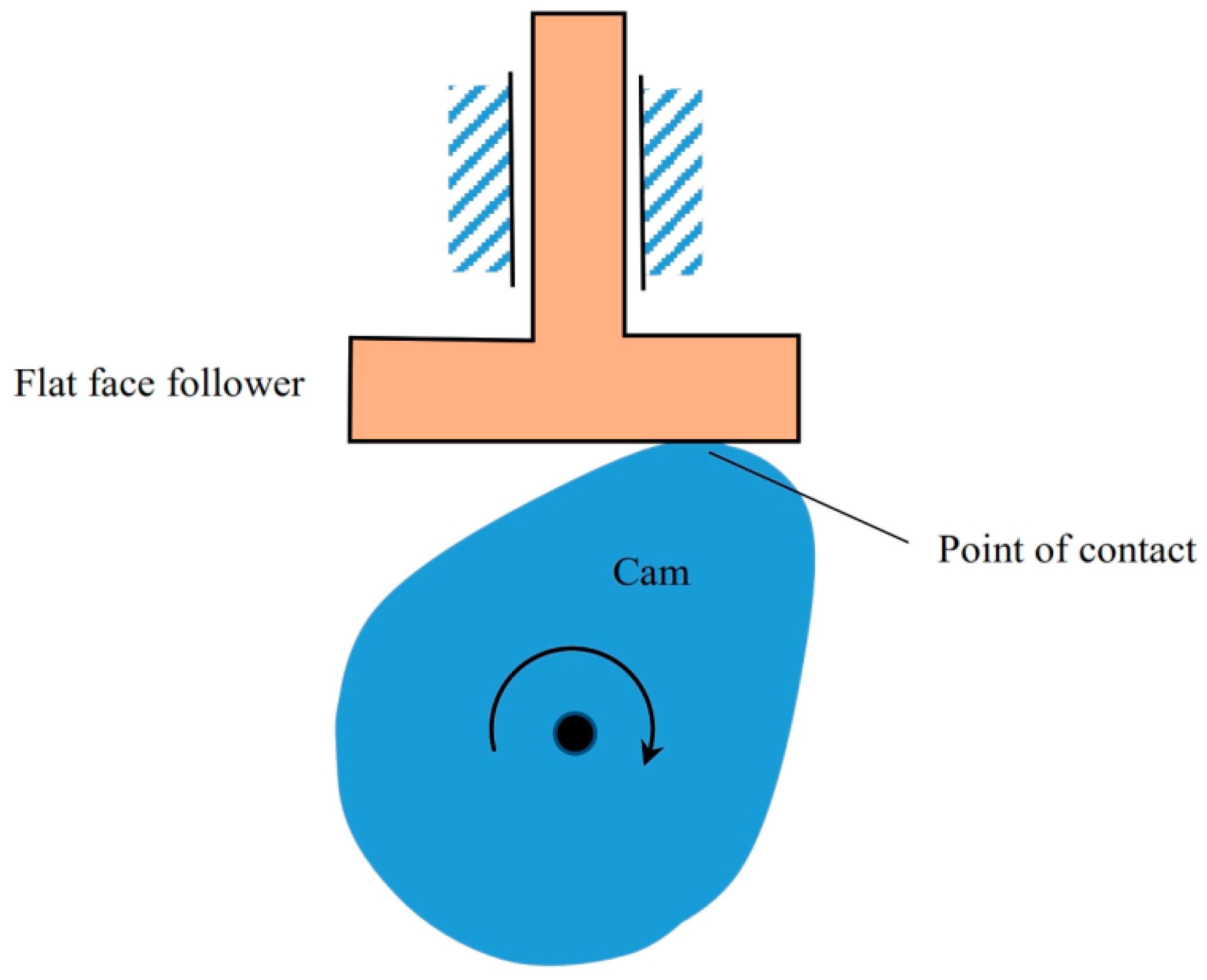
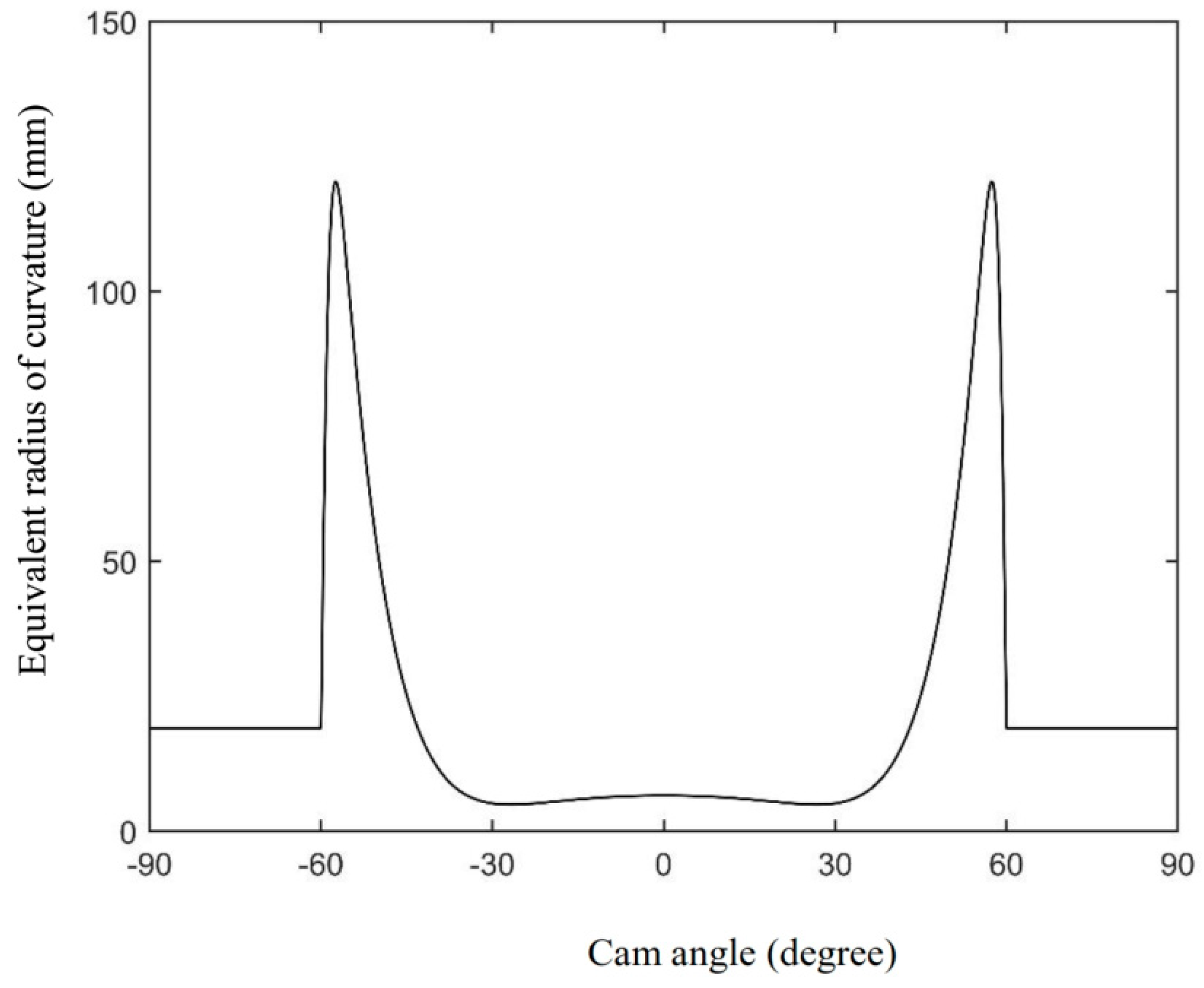
Figure 2 shows the velocity of the cam and the follower relative to the contact point. In this figure it can be seen that the velocity of the cam and the follower is maximum at the cam flank. In
Figure 2 it can also be seen that the velocity difference between the cam and the follower that is known as the sliding speed
, is an important factor in the formation of the EHL, so that it will be investigated carefully along the cam. For the cam and follower considered in this study, the maximum sliding velocity occurs at the cam nose, so that this will be one of the regions which will be studied in terms of EHL point of view. For the point contact EHL solution, the equivalent radius of curvature of the contacting surfaces is used as following
where
R = equivalent radius of curvature;
Rc = cam radius of curvature;
Rf = follower radius of curvature.
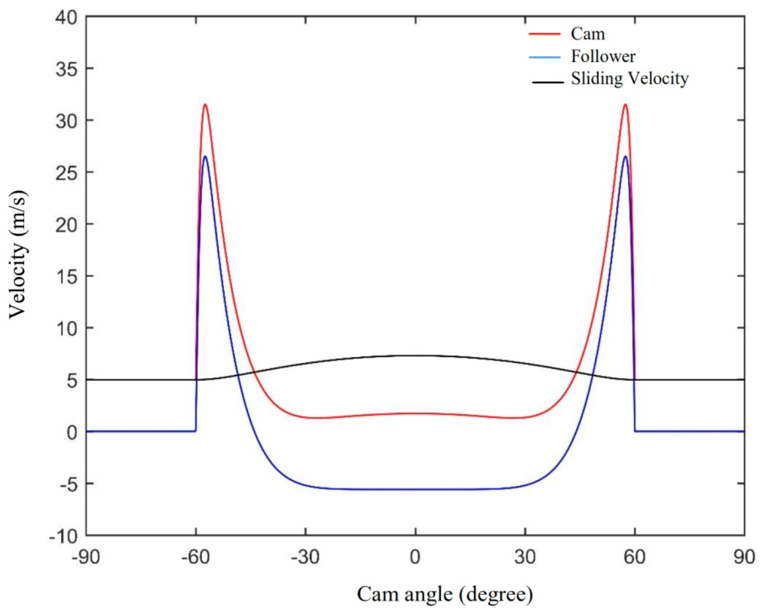
The equivalent radius of curvature for the cam and follower used in this paper is equal to
Figure 3 shows the equivalent radius of curvature along the cam angle.
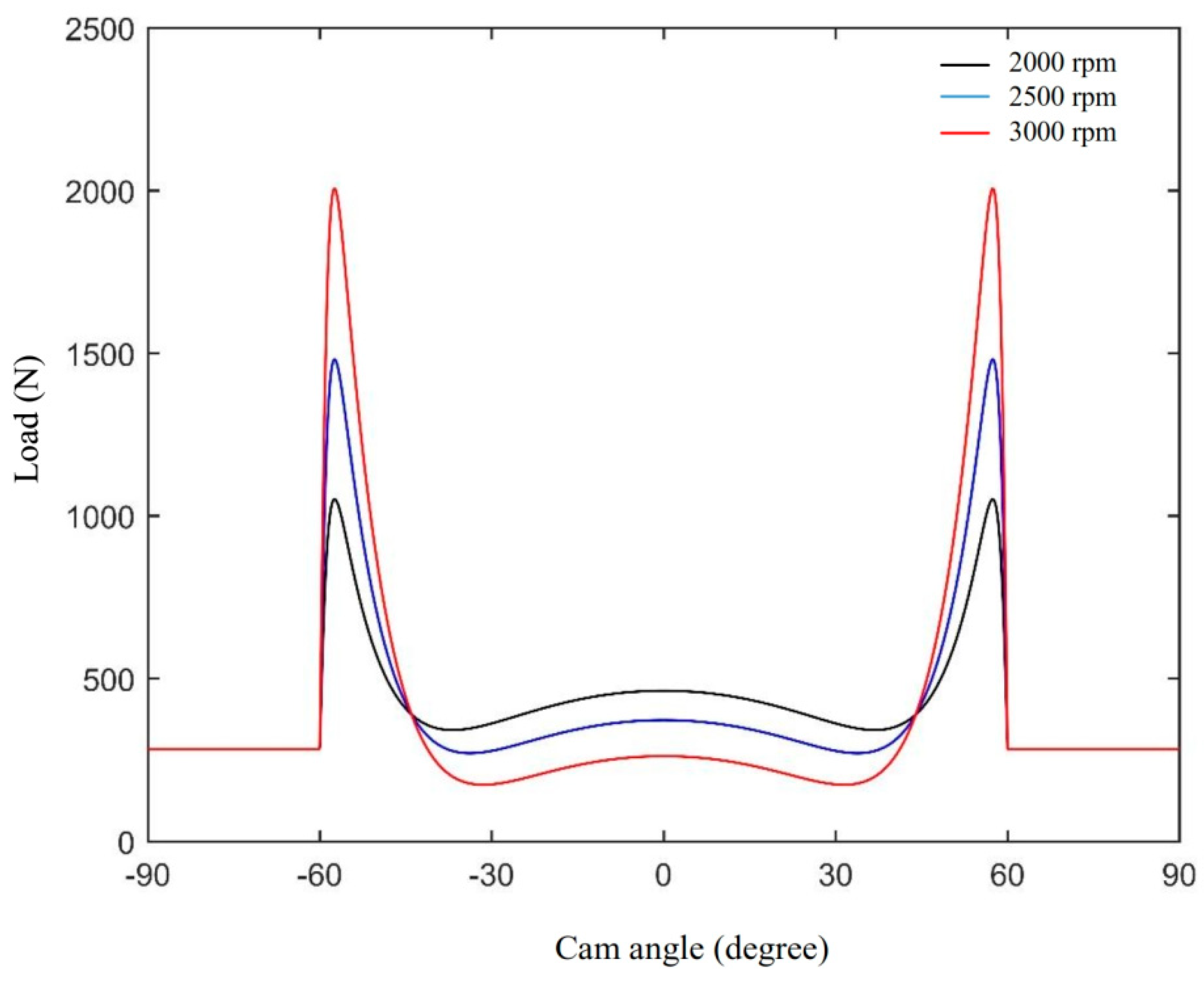
Figure 4 shows the load at the contact region versus the cam angle for a range of cam speed of rotation. Similar to
Figure 2, the maximum radius of curvature is also at the cam flank. This should be considered in the analysis of the lubrication of the cam follower mechanism.
The load at the contact region is another important parameter affecting the EHL solution. For the cam-follower mechanism, the load is contributed mainly by the inertia force of the follower and the force comes from the spring that is used to hold the follower. Any other forces, such as friction or performing force, are neglected in this study. So that, the load is represented by two terms in the equation below, the first term represents the spring force and the second term represents the inertia force of the follower.
where
k = spring constant;
δ = initial deflection in the spring;
M = mass of the follower;
= the acceleration of the follower.
Figure 4 shows the load versus the cam angle of rotation for a range of angular speed of the cam. It can be noted in this figure that the maximum load is at the flank. It can also be noted that the load is highly sensitive to the rotational speed of the cam for the range considered. This load increasing against the rotational speed is due to the rise in the follower acceleration as the angular speed is increased. This will be studied in the next sections of this paper.
3. EHL Solution
The complete solution of the EHL contact of the cam-follower system requires a coupled solution for the Reynolds and the film thickness equations. These equations for quasi steady-state solution are [
20],
where
: constant;
: local surface deformation;
: gap between the two surfaces;
plane: is the tangent to the cam and follower surfaces at the contact point,
and
= 0 for the cam follower system as there is no surface velocity in the
y direction. The surface velocities
and
with respect to the point of contact are given by Equations (1) and (2) previously. The flow factors for Newtonian behavior are
For the non-Newtonian oil behavior, the Johnson and Tevaarwerk [
21] relation is used in order to determine the flow factors. This equation relates the shear stress and stress rate in the following non-linear form:
For the equation that describes the relation between viscosity and pressure, the Roeland [
22] equation is used in the present paper in the form given by Lugt and Morales [
23] for isothermal solution:
where,
.
Dowson and Higginson [
24] relation is used for the dependency of density on pressure which is,
For the film thickness equation, the gap between the cam and the follower, which is the first term, needs to be determined as part of the full solution of the EHL problem.
Figure 1 (as explained previously) shows a typical flat-faced follower system where the cam has unmodified depth which represent a 2D EHL problem as mentioned previously.
The gap between any two surfaces in non-conformal contact depends on their radii of curvature which are given by Equation (4), thus the gap between the cam and follower is [
25],
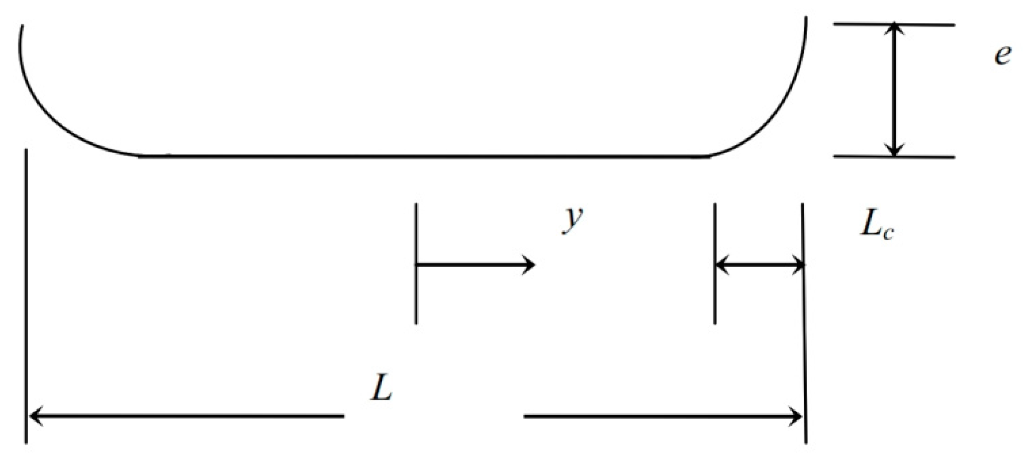
In the case of modified cam depth, the form of modification is shown in
Figure 5 [
26]. It can be seen in this figure that a chamfer of height
e at the edges of the cam depth is added over a distance
Lc. The length ratio of modification is given by,
Changing the
ratio gives different forms of modification.
, for example, represents the case when the whole cam depth is modified and when
corresponds to the unmodified profile. A wide range of
is considered in this paper. The corresponding gap for the modification in the right-hand side of the cam profile can be easily given by:
It is worth mentioning that the slope of the curve given in Equation (15) is zero at the start of modification (. This is an important issue to avoid any discontinuity in the profile which causes a high stress concentration level. A similar equation can be easily derived for the modification of the left side.
Thus, the total gap in the
x-
y plane is,
The second term in the film thickness equation is the surface deformation. The deformation of the cam and follower surfaces can be determined using the following equation [
25],
where,
are the
x and
y positions of the point under consideration respectively,
: Poisson’s ratio;
E: modulus of elasticity.
The central difference method is used for the discretization of the Reynolds equation. The solution of the resultant system of equations is carried out using different mesh size in both directions of the solution domain (
x-
y plane). Where, this test is performed to examine the effect of mesh size (or in other words the number of nodes) on the minimum film thickness. In this procedure or mesh independent test, the number of nodes
and
in the
x and
y direction respectively were approximately doubled each time. The results of this test reveal that increasing the number of nodes more than
(total number of nodes = 98,464) has a trivial effect on the calculated minimum film thickness. This is an expected result as very fine mesh is only required when the surface irregularities are taken into consideration as in reference [
27]. Therefore, this mesh size is adopted in the present analyses. In all cases that are studied in this paper the convergence to the load corresponding to the cam angle of rotation is obtained. This can be achieved by integrating the pressure over the entire solution domain and comparing the result of this integration with the given applied load. The load convergence sequence is controlled through changing the constant
in the film thickness equation (third term in Equation (8)) until convergence is accomplished. This is achieved during the execution of the solution process. The material and lubricant properties used in this paper are:
E = 207 GPa,
= 0.3,
= 0.005 Pa·s,
= 22 GPa
−1,
= 10 MPa.
4. Results and Discussions
The results presented in this section covered both the full
and partial modification of cam depth where different length ratio
is considered.
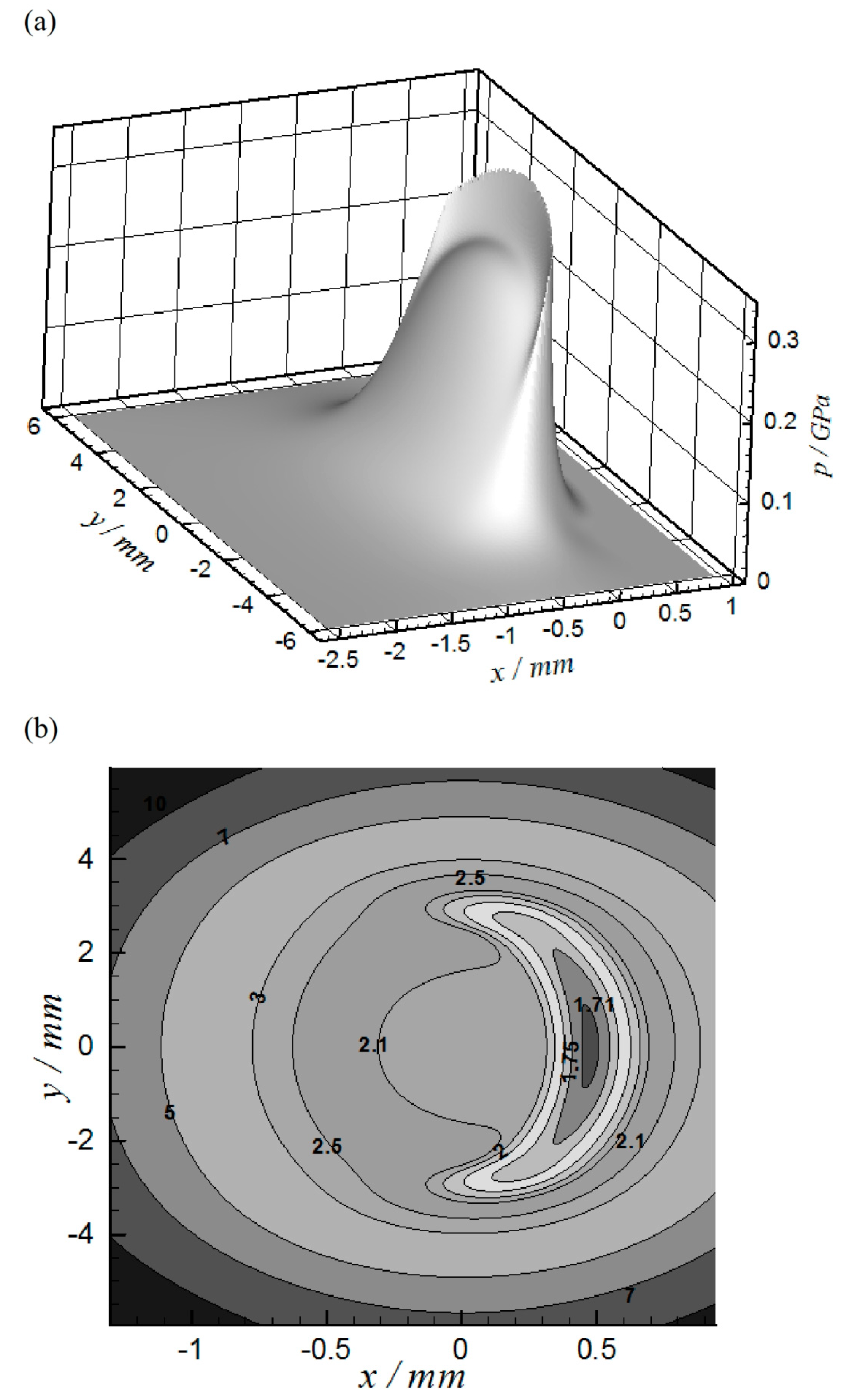
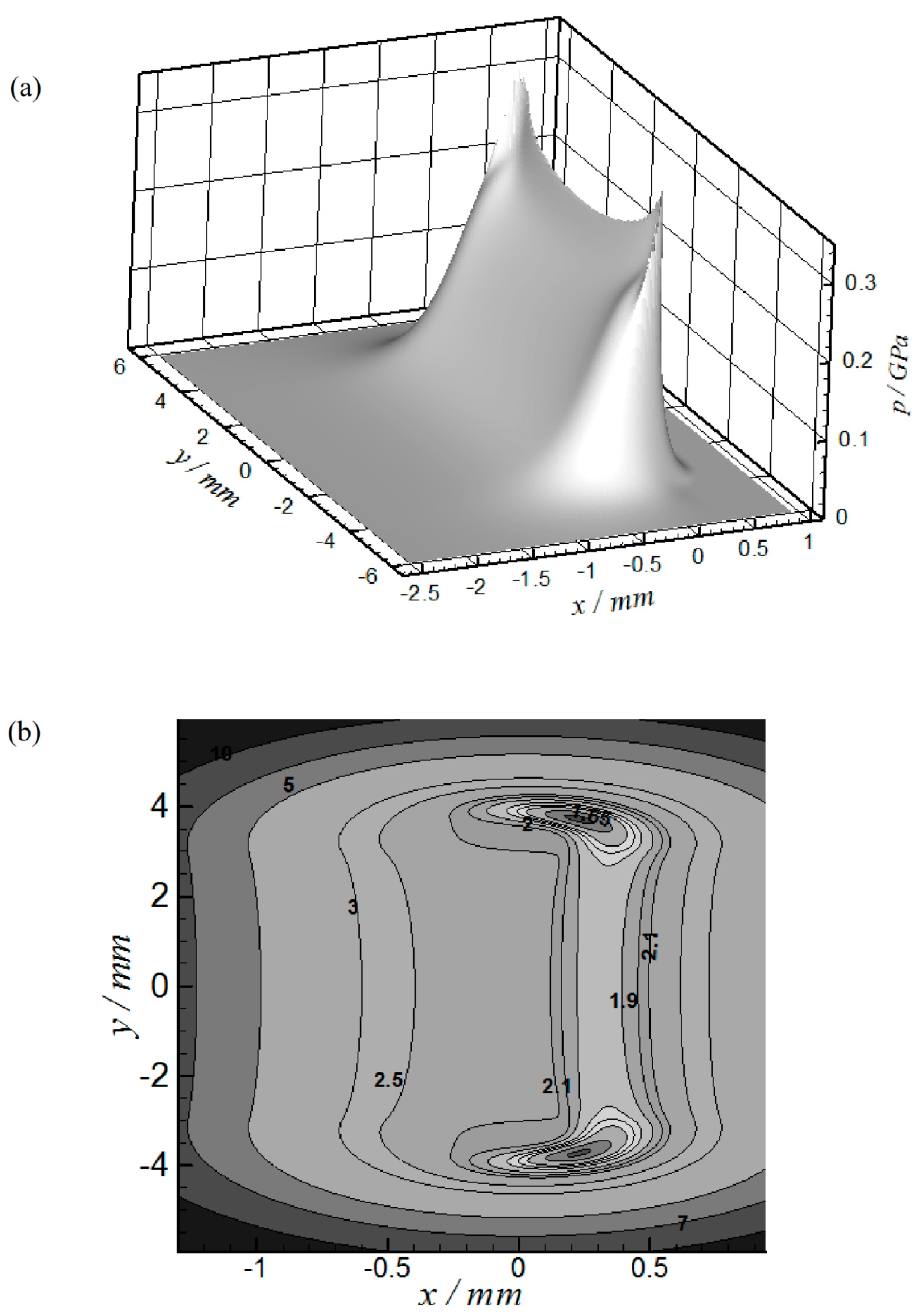
Figure 6 shows the EHL results when
at
= 57.4° where the load is maximum at this position, as explained previously.
Figure 6a represents the 3D pressure distribution while
Figure 6b shows the 2D film thickness contour. The maximum pressure at this position is 0.375 GPa and the minimum film thickness is 1.701 µm which represents a relatively high level of film thickness in the common EHL contact problems (e.g., ball bearing, gears, etc.). However, higher pressure levels have been predicted at other positions in the mechanism operating cycle as will be seen later. The horseshoe can be seen clearly in the film thickness contour which is a typical shape commonly appeared in point contact results.
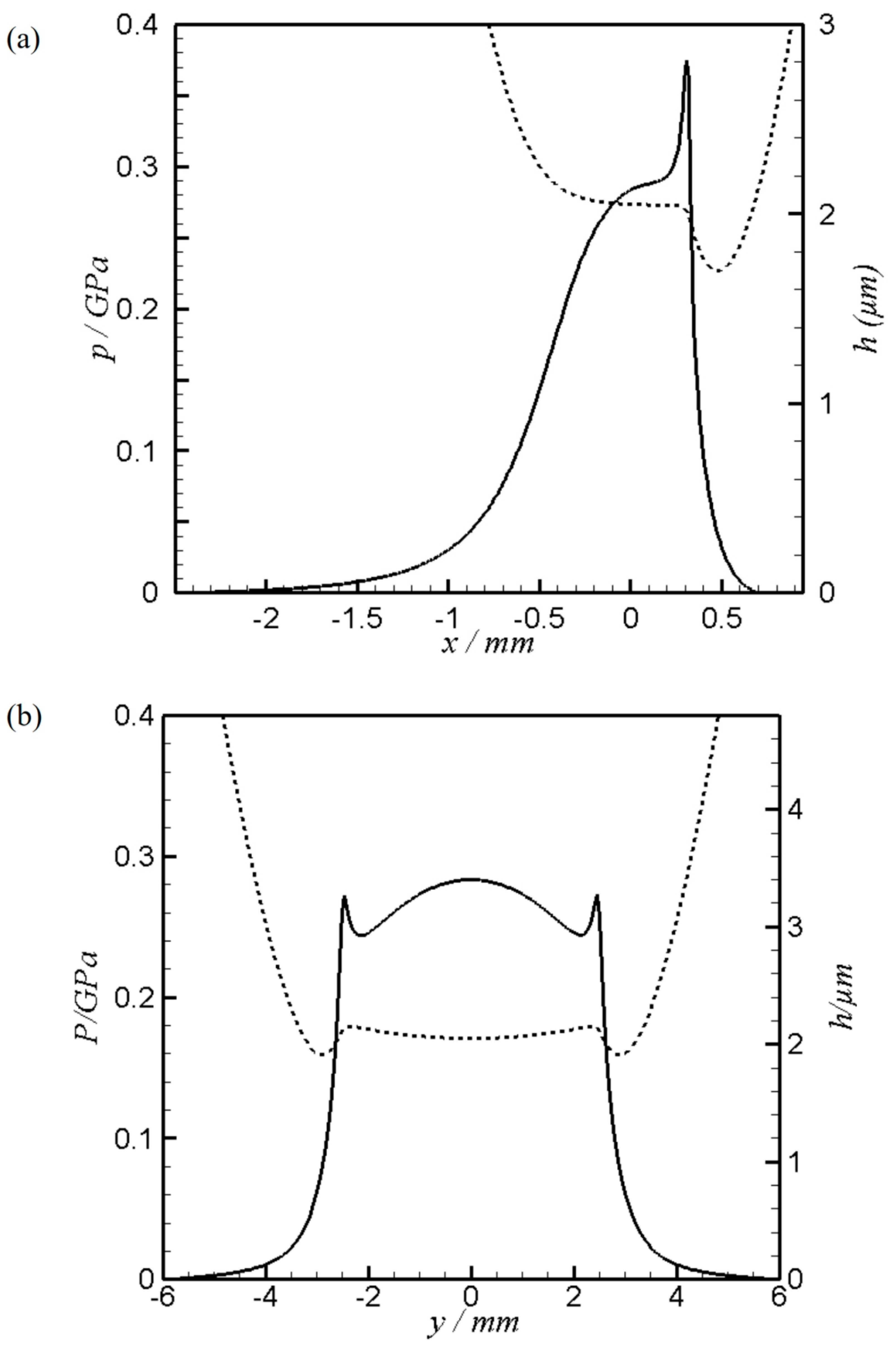
Figure 7 illustrates the results of sections at the center of contact for the case shown in
Figure 6.
Figure 7a shows the pressure and film thickness variation along the
x-axis at
and
Figure 7b shows the corresponding results along the cam depth (
y-axis) at
. It can be seen in
Figure 7a that the pressure is generated upstream over a relatively long distance from the center of contact (
x = 0). This in general is either related to the inadequate amount of lubricant at the inlet which is commonly called
starvation or due to the magnitude of contact load with respect to the size of contact. If the load is high, the oil that separates the two contacting surfaces is pressurized over a relatively narrow area and vice versa for a lower load. The relatively low level of load at some positions in the mechanism operating cycle is the reason behind generating the pressure over relatively long distance from the center of the contact. This is carefully examined in this paper to ensure fully-flooded regime [
27] which sustains an application of accurate boundary conditions in the solution of the Reynolds equation [
28].
The effect of cam rotation speed on the contact characteristics is shown in
Table 1. Three different rotation speeds are taken into consideration which are
, 2500 and 3000 rpm. Three critical positions are examined at these rotation speeds which are
,
= 44° and
= 57.4°. These positions in a complete operating cycle of the cam have the following conditions: Maximum sliding speed, zero surface velocity of the follower (with respect to the point of contact) and maximum contact load respectively. The results shown in
Table 1 demonstrate that the lowest level of
is found at
. At this position, despite the load being much less than the maximum, the effect of sliding speed, which is maximum here, is the dominate factor for the level of
.
In general, as the rotation speed increases, the minimum film thickness level, , is also increasing. At the position , for example, = 0.073 μm at rpm compared to = 0.1019 μm at rpm which means in other words an increase of 39.6% in the minimum film thickness level. The same behavior is also found in the results of the other two positions where the increase in when changed from 2000 to 3000 rpm is 32.7% and 26% at position and respectively.
It is worth mentioning that the contact load is significantly related to the rotational speed of the cam at some positions during the cam rotation as explained previously, but the minimum film thickness is less affected by the change of load as it is related to the load by
[
29]. The maximum pressure values are less sensitive to the variation of the cam rotation speed but it is more related to the load variation. This is clear at position
where
almost has the same value despite the change of the cam rotation speed. This is due to the relatively small change of the load with the change of rotation speed at this position. The highest change can be noticed at
where the load is significantly changed at this position.
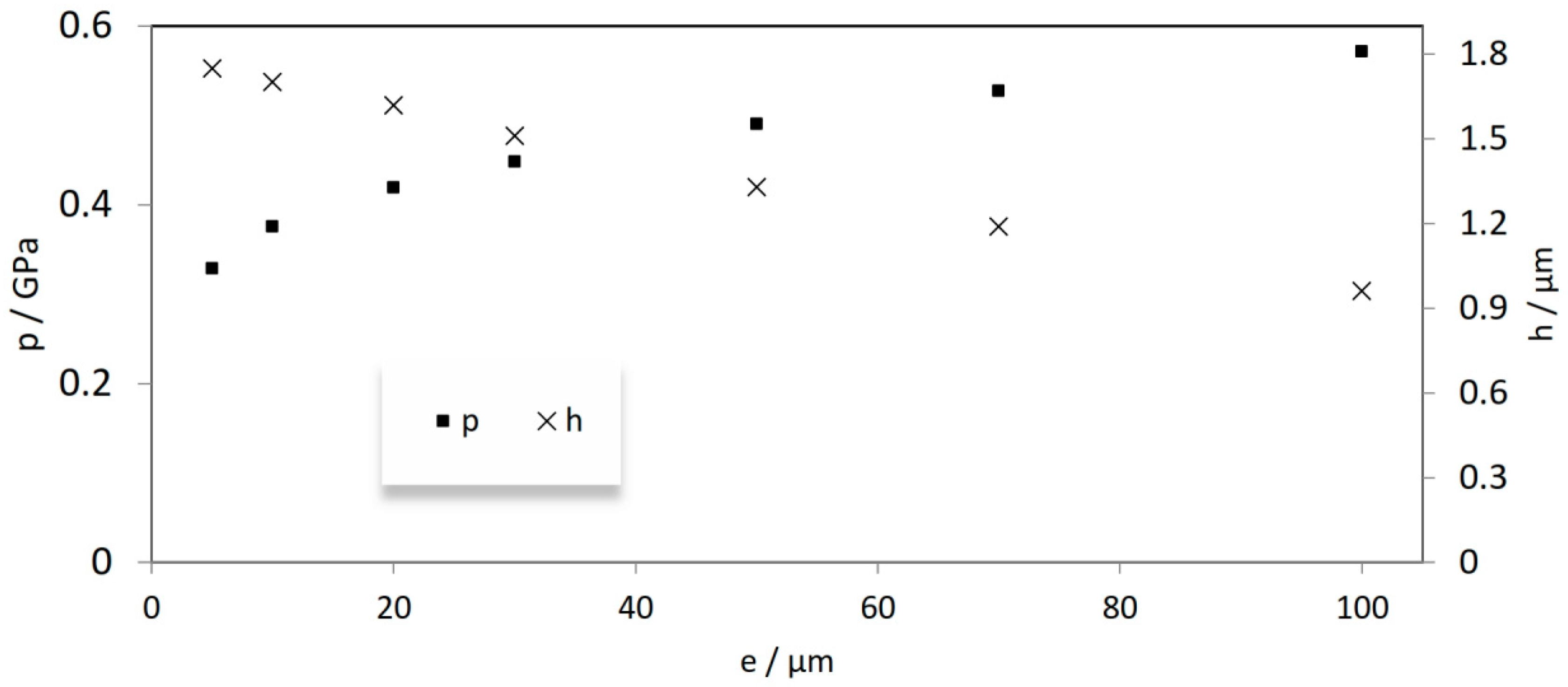
The effect of introducing a curvature along the cam depth on the EHL results is shown in
Figure 8. It can be seen from this figure that the maximum pressure and minimum film thickness are strongly related to height of modification,
e, at the cam edges. For the case when = 10 μm,
= 1.701 μm and
= 0.375 GPa while when
= 100 μm,
= 0.961 μm and
= 0.571 GPa. These changes represent a reduction of 43.5% in minimum film thickness and an increasing of 52.2% in the corresponding maximum pressure value. The results shown in this figure emphasized the necessity of determining the optimum
value for each cam application.
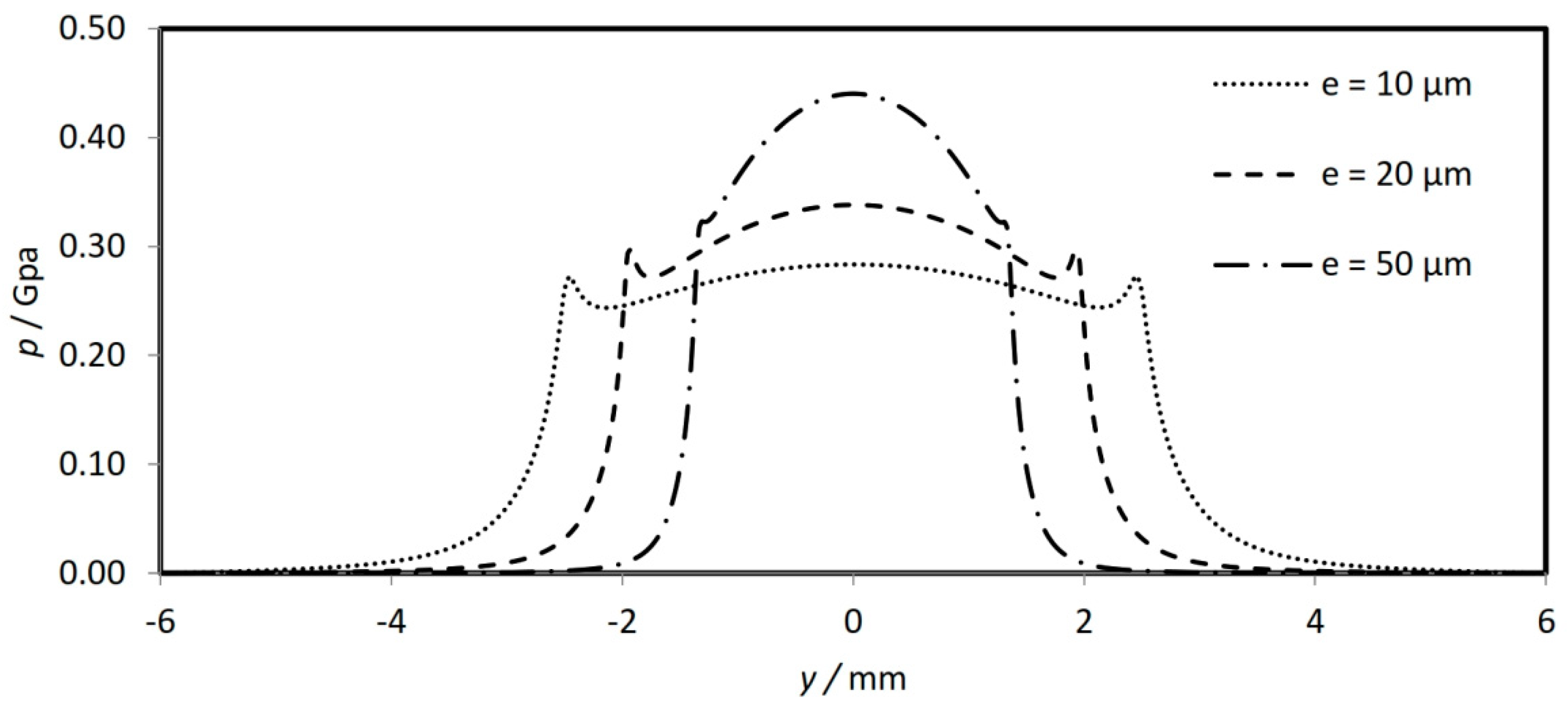
The solution of any differential equation (which is the case for the Reynolds equation) requires application of pre known boundary conditions along the boundaries of the solution domain, which in the present case are
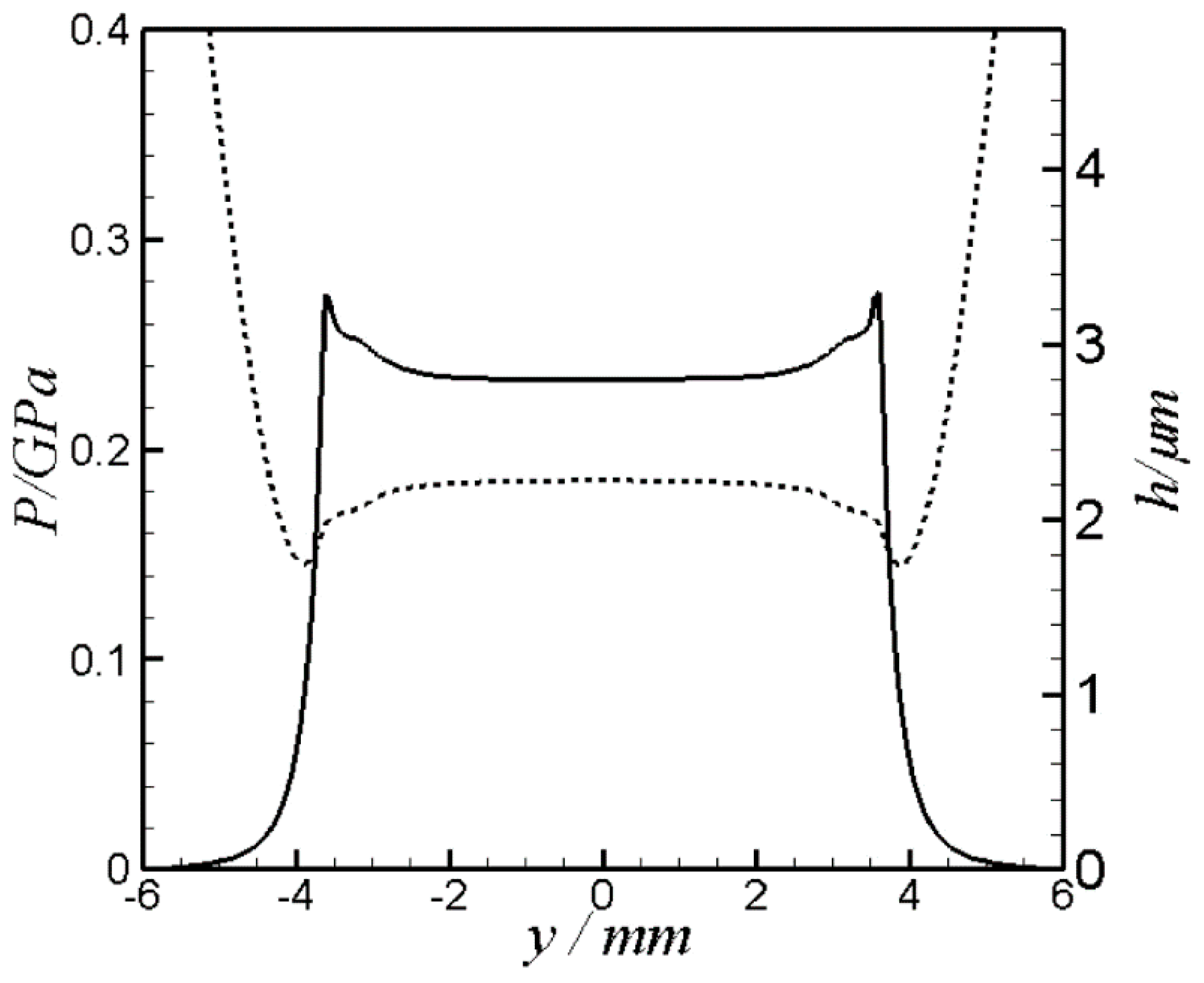
. Imposing the boundary conditions needs to be on locations far enough from the center of contact to ensure no pressure can be generated on those locations, otherwise the whole solution is far from being the right one. This can be clarified more by observing the results shown in
Figure 9. This figure illustrates the pressure variation along the cam width at the center of contact (i.e.,
) when
= 10, 20 and 50 μm. In all cases no pressure is generated close to the cam edges (at
= −6 mm and
= 6 mm). Therefore, these positions of boundary conditions are adequate for the solution of the Reynolds equation.
Figure 8 and
Figure 9 show that the case when
= 10 μm gives the best
and
from one side and maintains the right solution for the Reynolds equation on the other.
The modification of the whole profile was discussed above and the effect of adding chamfer will be discussed here to have a clear picture for the possible differences between the outcomes of the two methods of modification. The EHL result for the case
is shown in
Figure 10.
Figure 10a,b shows the 3D pressure distribution and 2D film contours respectively where
= 0.372 GPa and
= 1.601 μm.
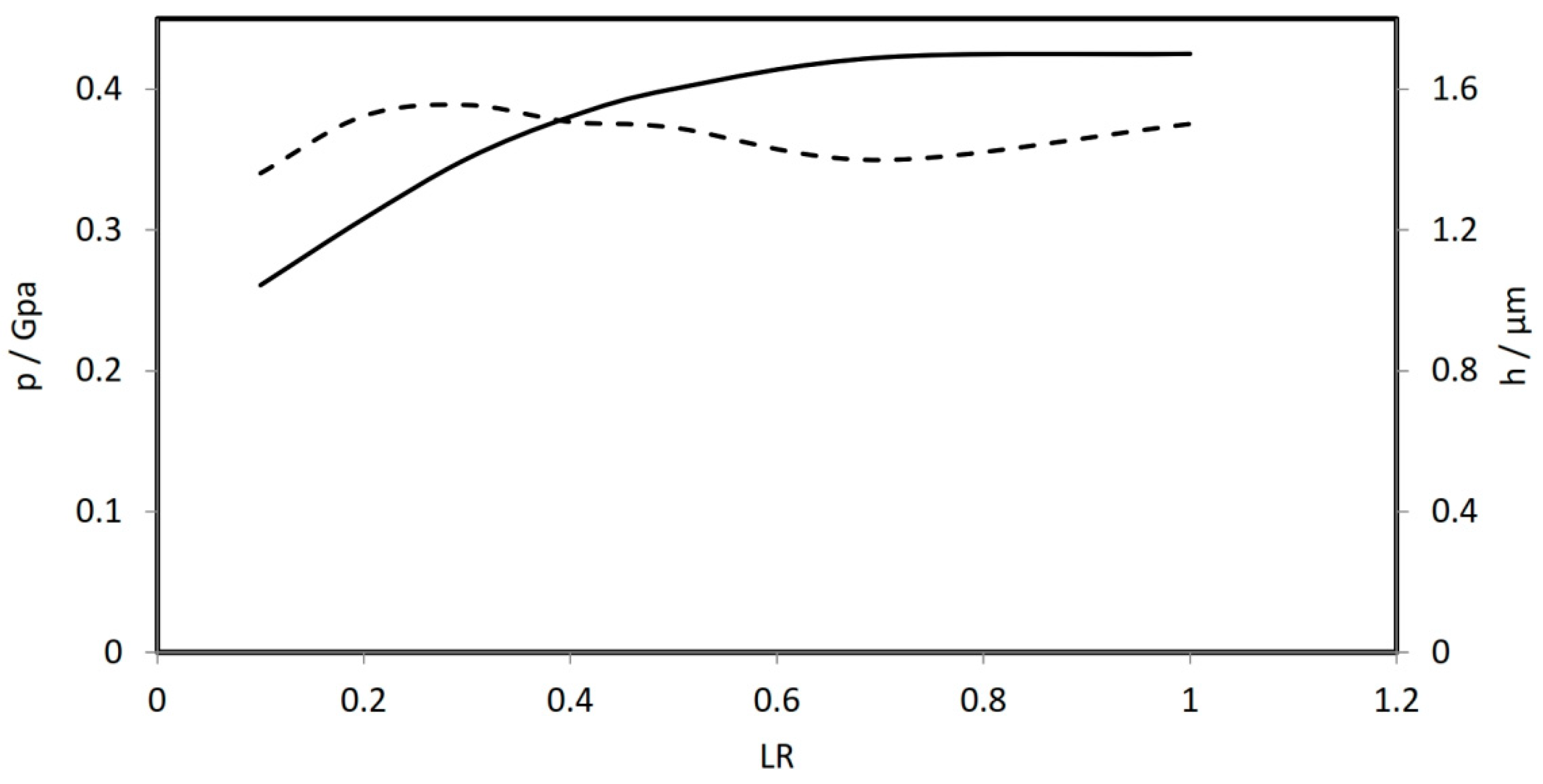
Figure 11 shows the results when the cam length is chamfered over a distance
measured from the cam edge on each side with
= 10 μm. The results illustrate that the minimum film thickness increased as the distance
increased. When
= 0.1,
= 1.043 μm while for
= 1,
= 1.701 μm which means an increase of 63%. It is worth mentioning that when
= 1 the case is exactly the same as discussed above, i.e., modification of the whole cam length. The results shown in this figure illustrate an important outcome which is
does not significantly change for
. This means, it is not necessarily to modify the whole length of cam. Adding chamfer over one fourth of the cam length from each side is sufficient enough to have approximately the same level of
obtained by modifying the whole cam length. Another important finding can be drawn from this result is that adding chamfer over a relatively small distance
reduces the level of
significantly. Therefore, adding the chamfer needs to be over an appropriate distance which is found to be corresponding to
for the case under consideration. This figure also shows that
is not significantly related to
value particularly for
.
Figure 12 shows the variation of pressure and film thickness along the cam length at the center of contact (
). Although the values of
and
are not significantly different from that shown in
Figure 7 for the case of fully cam length modification (
), the shape of both pressure and film thickness contours are obviously changed. This is clearly due to the shape of cam depth which is fully modified when
in comparison to partially (one forth the cam length from each side) when
.
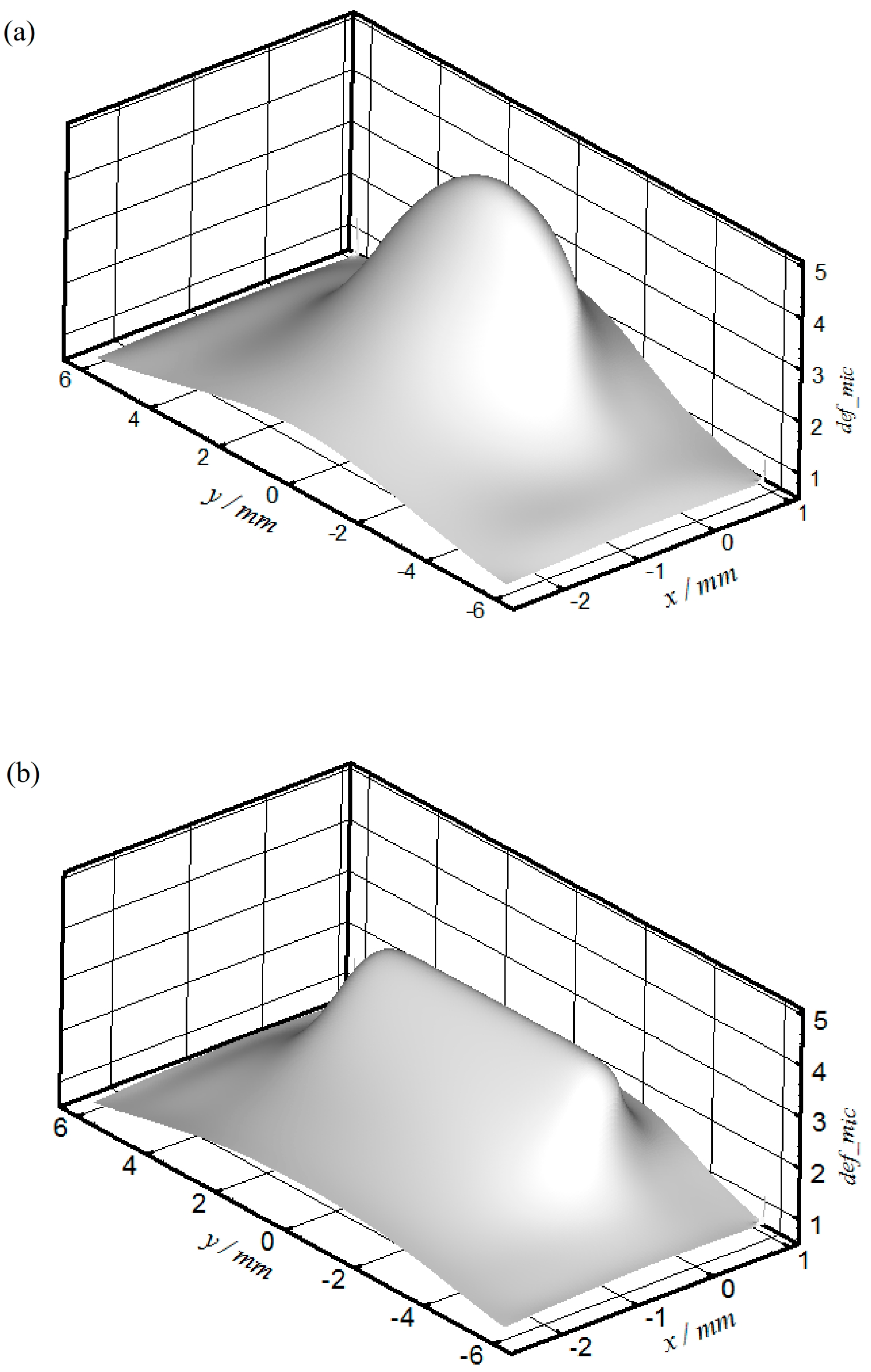
These results have its influences on the surface deformation which is shown in
Figure 13.
Figure 13a shows the deformation when
(i.e., full length modification) and
Figure 13b shows the corresponding deformation when
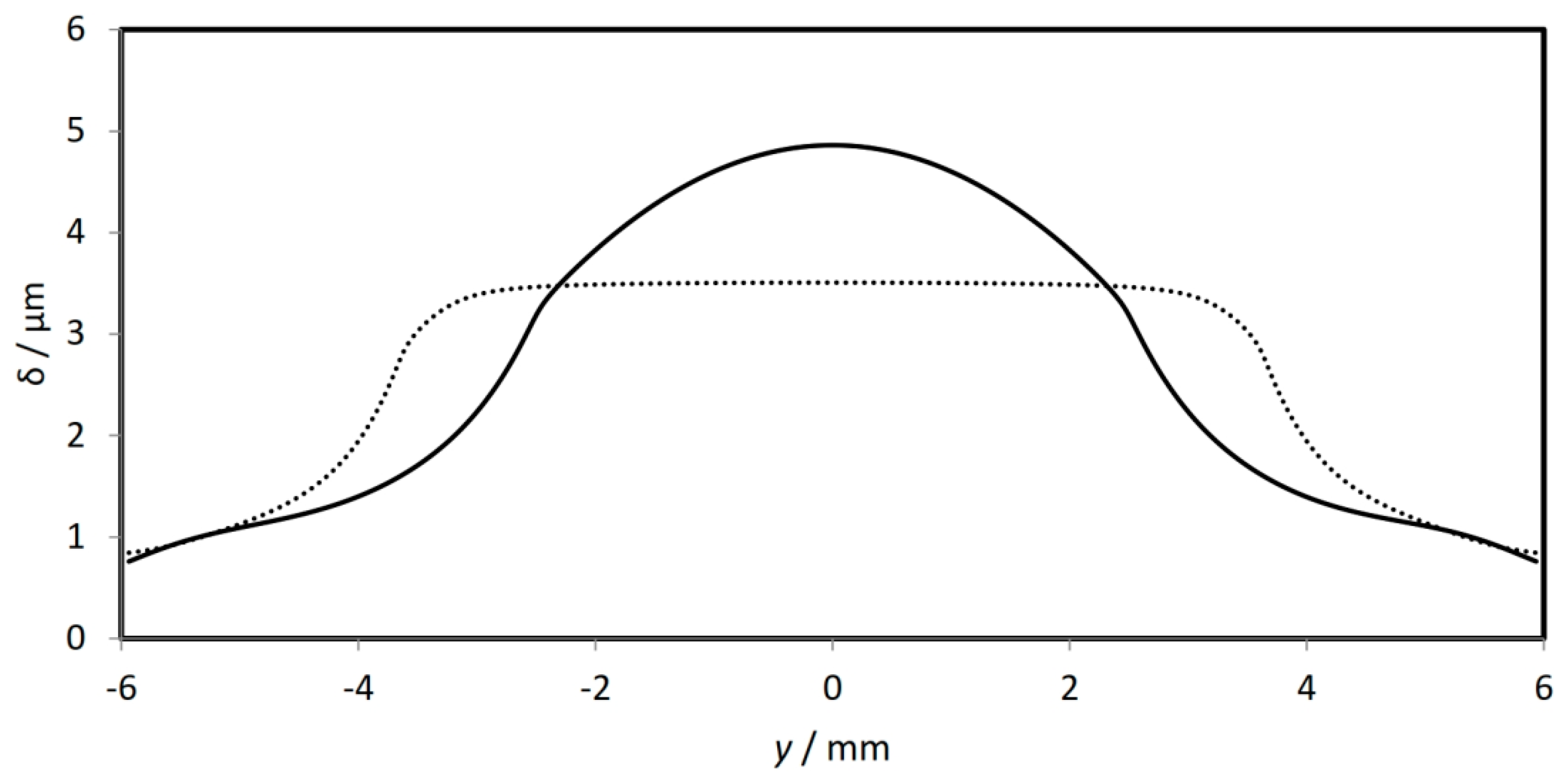
. This figure reveals the difference between the shape of deformation of the two cases. A clearer comparison is shown in
Figure 14 which illustrates the surface deformation along the cam length at
for the two cases shown in
Figure 13. The maximum surface deformation can be seen to be reduced from 4.86 μm when
to 3.51 μm when
(i.e., 27.8% reduction). This may represent an important outcome which is expected to be a significant effect on the cam life as the amount of surface deformation related considerably to the level of stresses in and underneath the surface of contact. The reduction in the level of deformation as well as the change in the shape of the pressure distribution when
LR = 0.5 in comparison with
LR = 1 may have effects on the level of these stresses. Any changes in such stresses consequently affect the fatigue life of the cam and the authors intend to inspect these effects in future work. The fatigue failure is considered as one of the major failure problems in structural and engineering components [
30].
It is worth mentioning that the current work is considered the quasi–static solution for the cam-follower contact problem with an emphasis on profile modification in the axial direction. However, the full picture of this mechanism cannot be evaluated without studying some other important issues. This includes the surface roughness, thermal effects, squeeze effect (full transient solution) and also the dynamic behavior of the mechanism where the follower might jump at a certain location with respect to the cam nose/tip. The cam follower contact is mainly in mixed regime of lubrication where the load in such case is partially carried by the asperities. Considering axial profile modification requires a point contact EHL model as explained previously, the mixed lubrication regime in such model requires a 3D measurement of the surface roughness in order to incorporate actual surface features in the analyses. Furthermore, incorporating the roughness in any solution model requires transient solution of the problem. From the author expertise, this is an extremely complex problem in transient cases when the area of contact is relatively large (the contact ellipse is relatively long in the major axis) where very large numbers of mesh points are required to accurately representing the surface features. It is observed from the available literatures that the researchers dealt with such problems (large contact area) in one of the following cases:
- -
Using an extruded roughness in the longer direction of the contact area.
- -
Using a finite length 3D roughness model where only part of the surface is used in the analyses with the assumption of repeating roughness profile. This is based on cyclic boundary conditions where fast Fourier transform is required. However, these approaches have significant limitations as they are only used for certain surface features. The surface roughness and the issues mentioned above will be considered in future works as surface modification is the major issue of investigation in the current work.


 and
and 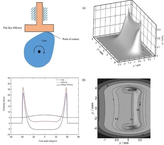


