Abstract
The wear of tibial inserts in total knee arthroplasty (TKA) remains a major limitation of longevity. However, wear tests are expensive and time-consuming. Computational wear prediction using a finite-element (FE) model followed by validation through comparison with experimental data is effective for assessing new prosthetic designs or materials prior to functional testing and surgical implementation. In this study, the kinematics, volumetric wear, and wear depth of tibial inserts made of different materials (ultrahigh-molecular weight polyethylene (UHMWPE), polyetheretherketone (PEEK), and carbon fiber-reinforced PEEK (CFR–PEEK)) in TKA were evaluated by employing FE models and analysis. The differences among the materials were evaluated using adaptive wear modeling to predict the wear depth, volumetric wear, and kinematics under a gait loading condition. The volumetric wear and wear depth of the CFR–PEEK decreased by 87.4% and 61.3%, respectively, compared with those of the UHMWPE, whereas the PEEK exhibited increased volumetric wear and wear depth. These results suggest that CFR–PEEK is a good alternative to UHMWPE as a promising and suitable material for tibial inserts used in TKA. However, orthopedic research should be performed to evaluate the threshold conditions and appropriate applications for the newly developed and introduced biomaterial.
1. Introduction
The development and improvement of orthopedic implants are gaining importance because of the increasing number of people undergoing surgeries to treat traumatic injuries and joint diseases, which always involve a risk of associated complications [1]. For example, among people aged 60 years old, knee osteoarthritis (OA)—a chronic, progressive, and degenerative knee joint disease that leads to wear, tear, and arthritis—is a common problem [2,3]. Total knee arthroplasty (TKA) is acknowledged by orthopedic surgeons to be one of the most effective treatments for improving function in pathologic knees [4]. However, complications can occur after TKA, including periprosthetic fractures, unexpected early wear, and revision arthroplasty [5]. In particular, the wear of ultrahigh-molecular weight polyethylene (UHMWPE) in tibial inserts remains a primary factor limiting the longevity of TKA [6].
To predict the wear of knee joints, experimental wear simulators have been developed for clarifying the wear mechanisms of ultrahigh-molecular weight polyethylene (UHMWPE), and pre-clinical evaluations of newly developed implant designs and tibial insert materials have been performed [7,8].
Newly developed orthopedic implants using innovative materials have been introduced in order to increase implant survival rates and reduce the burden associated with revision surgery. Polymer composite materials have been applied to medical devices, such as spine rods and disks, intramedullary nails, bone plates, and screws, and total-knee and hip replacements [9,10]. In these orthopedic implant materials, the requirements of the mechanical properties are remarkably high for improving the fatigue loading under the fluidic conditions of the body [9]. Polymer composite materials can satisfy such a requirement because they are widely used in many applications including medical implants due to their enhanced mechanical properties [11,12,13,14]. However, previous studies on polymer composites focused on the reduction of the stress-shielding effect of the polymer-composite implants due to the high stiffness of metal materials [15,16,17,18,19,20,21]. Polyetheretherketone (PEEK) and carbon fiber-reinforced PEEK (CFR–PEEK) have traditionally been used in spinal cages, bone fixation screws, and cardiac and neurological leads [1,22,23]. However, alternative materials have been investigated to improve the survivability of TKA for both young and old patients, and PEEK and CFR-PEEK have been introduced as alternative materials to UHMWPE for tibial inserts [24].
A recent study showed that PEEK has been used successfully in many clinical cases owing to its mechanical strength and biocompatibility. In addition, CFR-PEEK wear particles had no cytotoxic effects on cells in a culture and caused little or no adverse tissue reaction [25]. However, most manufacturers have used UHMWPE in tibial inserts for TKA, and few devices made of UHMWPE, PEEK, and CFR-PEEK have been researched or commercialized for wear prediction [1].
In vitro wear-testing machines are not ideal for evaluating tibial-insert and TKA materials in wear tests, because of their inefficiency with regard to cost and time. However, computational wear prediction using the finite-element (FE) method is practical, overcoming the disadvantages of in vitro wear evaluation using testing machines [26,27,28].
In this study, we predicted the wear of tibial inserts made of UHMWPE, PEEK, and CFR–PEEK via FE analysis. First, to estimate the wear, adaptive-remeshing Python scripts (Stichting Mathematisch Centrum, Amsterdam, The Netherlands) were used for the geometric modification of an FE model, and the user-defined subroutine VFRICTION was used for wear calculation. Next, the results were compared with the wear rate, volumetric wear, and kinematics from a previous study to validate the FE wear model. Then, the differences among the materials were evaluated using adaptive wear modeling to predict the wear depth, volumetric wear, and kinematics under a gait loading condition.
2. Materials and Methods
2.1. Computational Model
An existing explicit FE model and method for TKA were used in this study [29,30]. A three-dimensional explicit FE model for the GENESIS II Total Knee System (Smith & Nephew Inc., Memphis, TN, USA) was simulated using an in vitro knee simulator (Figure 1) [8]. The FE model was developed using computer-aided design models of fixed-bearing, cruciate-retaining TKA.
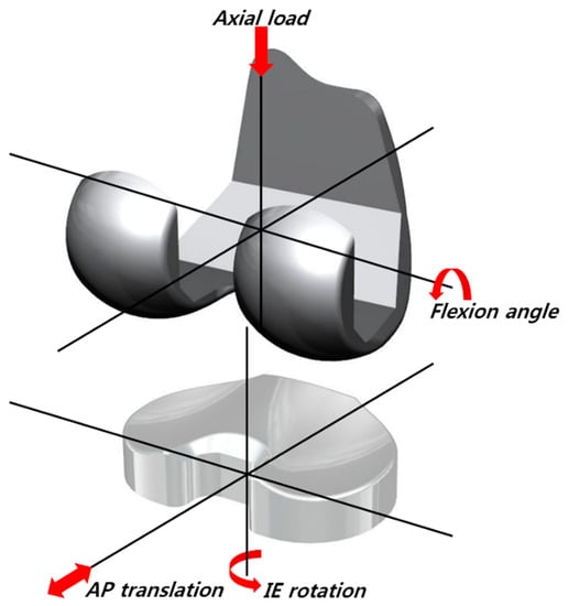
Figure 1.
The finite-element (FE) model used in this study.
The femoral component was modeled as a rigid body using four-node shell elements with an average edge length of 1.7 mm. The tibial insert was modeled using eight-node hexahedral elements. Solid modeling and meshing were performed using Hypermesh 11.0 (Altair Engineering, Inc., Troy, MI, USA), and analysis and post-processing were performed using ABAQUS 6.13 (Abaqus, Inc., Providence, RI, USA).
Convergence testing was performed to verify that the solution did not change appreciably with mesh refinement (Figure 2). We completed an average edge length test for six samples from 0.5 to 2.5 mm with increments of 0.4 mm. Three definitions of convergence were used in this study. The element edge length was reduced until the difference of the critical results, such as the peak contact pressure and the contact area between two consecutive mesh densities, was <2% in the gait cycle (Figure 2a). The difference between the root-mean-square values of the average contact pressure was <5% over the entire gait cycle (Figure 2b). Throughout the convergence test, the tibial inserts retained a consistent articular surface element average edge length of 1.3 mm. In this convergence study, it was concluded that the mesh density utilized for these inserts was acceptable compared to the results of previous studies [31,32]. The tibial insert contained 11,568 elements.
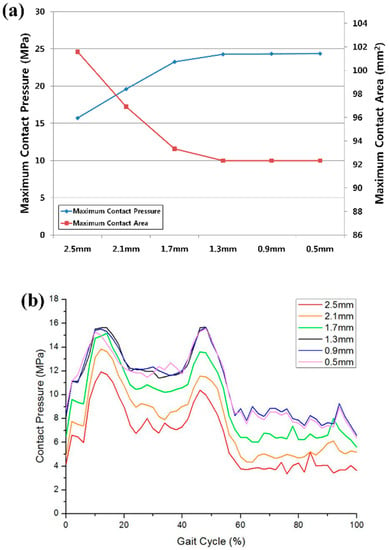
Figure 2.
Convergence test results for (a) the maximum contact pressure and contact area; (b) average contact pressure over the entire gait cycle.
The coefficients of friction between the articulating surfaces were assumed to be 0.07, 0.06, and 0.04 for UHMWPE, PEEK, and CFR–PEEK, respectively, in accordance with the range reported in the literature [26,29,31,32,33,34]. A penalty-based method was employed to define contact [29,31]. To improve the computational efficiency, both the femoral and tibial components were modeled as rigid bodies. The tibial insert was modeled as a deformable body.
The nonlinear pressure–overclosure relationship was specifically optimized for the mesh and loading conditions; thus, the kinematics and contact mechanics were predicted and compared with those obtained via a fully deformable analysis [26,29]. Contact forces were introduced as a function of the penetration distance of the master surface into the slave surface. To estimate the contact pressure and area in a rigid-body analysis, the softened contact capability was employed [26,31,35].
To validate the rigid body of the femoral component, the anterior–posterior (AP) translation, internal–external (IE) rotation, and contact pressure on the femoral component were evaluated and compared with those for a fully deformable body (Figure 3). Rigid-body and fully deformable body analyses predicted nearly identical AP and IE kinematics (Figure 3). These analyses predicted very similar trends for the contact pressure. The rigid-body analysis overpredicted the contact pressure for 49% of the gait cycle compared with the deformable-body analysis, but otherwise, the results matched well (Figure 3).

Figure 3.
Comparison between the deformable body and rigid body for (a) anterior–posterior (AP) tibial translation, (b) internal–external (IE) tibial rotation, and (c) contact pressure.
The UHMWPE was modeled as an elastoplastic material, and its material properties were obtained in our previous study [29,36]. PEEK and CFR–PEEK tensile tests were performed according to ASTM D638-0 by using an MTS 810.23 servo-hydraulic testing system. The CFR–PEEK comprised the pure PEEK material reinforced by 30% short carbon fibers. The material properties, i.e., the Young’s modulus (E) and Poisson’s ratio (v), were as follows: UHMWPE: E = 685 MPa, v = 0.47; PEEK: E = 3500 MPa, v = 0.3; CFR–PEEK: E = 18000 MPa, v = 0.4. The yield strengths of the UHMWPE, PEEK, and CFR–PEEK were 17, 100, and 225 MPa, respectively, and the ultimate tensile stress and the plastic strain for the UHMWPE were 33 MPa and 0.32, respectively.
2.2. Boundary and Loading Conditions
The explicit TKA FE model was a fully dynamic model that predicted the motions in the knee joint and the stresses exerted on the tibial insert under the ISO gait loading condition (Figure 4). The axial force, AP translation, and IE rotation were force-controlled, whereas the flexion was displacement-controlled.
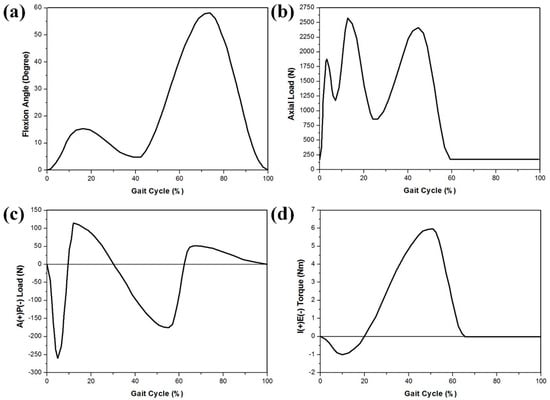
Figure 4.
FE model inputs with respect to the ISO gait cycle: (a) flexion angle; (b) axial load; (c) AP translation; (d) IE rotation.
The kinematics, contact mechanics, and wear performance were evaluated using an FE model developed with the Stanmore knee simulator condition. Soft-tissue constraints were reproduced using a mechanical spring-based assembly with four linear springs (Figure 1). The flexion and axial forces, as well as the AP load and IE torque, were applied to the femoral component and tibial insert, respectively. The femoral component was free in the medial–lateral (ML) direction, AP direction, varus and valgus (VV), and was constrained in IE rotation. The axial load application was offset toward the medial condyle to reproduce the 60:40 experimental conditions. The tibial insert was free in the ML and VV directions, while it was constrained in the superior–inferior and flexion–extension. The center of rotation for the FE model was defined between the medial and lateral condyles. The AP spring translational and IE rotational stiffness were 10.4 N/mm and 0.30 Nm deg-1, respectively.
2.3. Computational Wear Simulation
The wear of UHMWPE, PEEK, and CFR–PEEK was numerically formulated using the Archard wear model [37]. In 1953, Archard introduced an equation for evaluating the linear wear depth perpendicular to the wear surface between two metal surfaces sliding against each other. The following equation is known as Archard’s wear law:
where H is the linear wear depth, Kw is an experimentally determined wear factor, p is the contact pressure, and S is the sliding distance. The wear factors of UHMWPE, PEEK, and CFR–PEEK for the tibial-insert material employed in this study were estimated according to the average wear factors for TKA and ball-on-flat wear tests from the literature [38,39,40].
H = KwpS
The general computational wear models are based on Archard’s wear law with arbitrary wear factors to match the experimental wear from the simulator machine. The disadvantage of Archard’s equation for predicting wear in TKA is that it does not consider changes in the sliding direction and the resultant wear increase [41,42]. Additionally, delamination, pitting, and third-body wear are not considered; however, previous studies showed that these effects are negligible for a tibial insert. The Sarkar correction with the friction parameter μ was applied to the Archard model [43]:
H = KwpS (1 + 3μ2)0.5
The Archard model was used to estimate the wear and predict the geometry modifications of the tibial insert due to the wear after a certain number of cycles. The femoral component was assumed, without modifications. The wear was considered to be constant for a certain number of cycles (Figure 5).
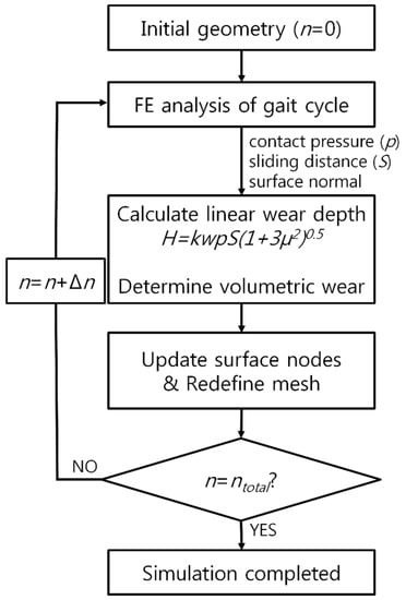
Figure 5.
Flowchart for the wear evaluation in the FE analysis.
An adaptive remeshing wear simulation was performed using Python scripts (Stichting Mathematisch Centrum, Amsterdam, The Netherlands) that interfaced with the Abaqus output [26]. The model for predicting the wear on the tibial insert was incorporated into the user subroutine VFRICTION using the FORTRAN code. The simulation was repeated, and the wear was multiplied by the size of each step (50,000 cycles per step) to evaluate the total wear after 5 million cycles. This update interval was shorter than those used in previous computational studies on TKA wear [26,44].
The results of the wear simulation for the UHMWPE tibial insert were validated through comparison with previous experimental studies [45,46,47]. The kinematics, wear depth, and volumetric wear of UHMWPE, PEEK, and CFR–PEEK were compared.
3. Results
3.1. Validation of UHMWPE Wear Model
To validate the model for predicting the wear on the tibial insert, it was compared with a previous in vitro wear experiment with regard to the volumetric wear rate [46,47]. The wear rate of the model for estimating the wear of the UHMWPE insert was 24.90 mm3/million cycle, and that from the in vitro experimental data of Morrision et al. was 23.4 ± 2.4 mm3/million (Table 1) after 1 million cycles [46]. The volumetric wear after 5 million cycles was compared with the experimental results of Papannagari et al. [47]. The predicted volumetric wear of the UHMWPE tibial insert was 124.04 mm3. This value was determined to be 120.42 ± 11.99 mm3 in the in vitro experiment (Table 1). The predicted wear rate and volumetric wear for the UHMWPE tibial insert were within one standard deviation of the in vitro experiment data [46,47]. The results for the tibiofemoral kinematics, UHMWPE tibial insert, and validation showed good agreement between the predicted and experimental kinematic data [45]. The AP translation and IE rotation were reasonably similar to those of the experimental data with regard to the trend and magnitude (Figure 6). The ranges of the AP translation and IE rotation from the experimental data were 7.1 mm and 9.3°, respectively, and the predicted displacement ranges were 6.7 mm and 9.1°, respectively.

Table 1.
Comparison between computational simulation and previous experimental studies for wear rate and volumetric wear in UHMWPE.
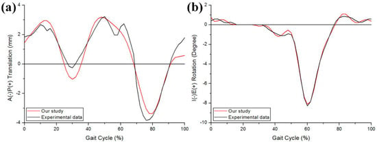
Figure 6.
Comparison of the kinematics in (a) AP tibial translation and (b) IE tibial rotation between the computational simulation and a previous experiment.
3.2. Comparison of Kinematics, Wear Depth, and Volumetric Wear in UHMWPE, PEEK, and CFR–PEEK Tibial Inserts
Figure 7 shows the tibiofemoral kinematics for UHMWPE, PEEK, and CFR–PEEK under the gait loading condition. The greatest AP and IE movements are observed for the UHMWPE model, followed by PEEK and then CFR–PEEK. The posterior translations and internal rotations in the PEEK and CFR–PEEK models were relatively small under the gait loading condition.
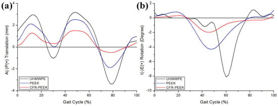
Figure 7.
Comparison of the kinematics in (a) AP tibial translation and (b) IE tibial rotation for the UHMWPE, PEEK, and CFR–PEEK models.
Figure 8 shows the relative contributions of the contact area and contact pressure. The average instantaneous peak contact pressure over the entire gait cycle was calculated to be 13.4, 23.6, and 36.1 MPa for the UHMWPE, PEEK, and CFR–PEEK models, respectively. The volumetric wear and wear depth in UHMWPE, PEEK, and CFR–PEEK after 5 million cycles are presented in Table 2. The volumetric wear was 124.0, 300.9, and 15.6 mm3 for UHMWPE, PEEK, and CFR–PEEK, respectively, after 5 million cycles. Compared with UHMWPE, after 5 million cycles, the volumetric wear in CFR–PEEK was 87.4% smaller, and that in PEEK was 142.7% larger. The maximum wear depth was 0.31, 0.89, and 0.12 mm in UHMWPE, PEEK, and CFR–PEEK, respectively, after 5 million cycles. Compared with UHMWPE, after 5 million cycles, the wear depth in CFR-PEEK was 61.3% smaller, and that in PEEK was 187.1% larger. Figure 9 compares the predicted wear contours for UHMWPE, PEEK, and CFR–PEEK, indicating that CFR–PEEK had a smaller wear depth than UHMWPE and PEEK. All the wear-prediction models exhibited a deep wear scar in the central region on the medial side, as well as a smaller, shallower patch on the lateral condyle.
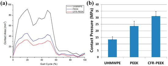
Figure 8.
(a) Contact areas in the UHMWPE, PEEK, and CFR–PEEK models plotted over the entire gait cycle. (b) Average contact pressures computed for the UHMWPE, PEEK, and CFR–PEEK models across for all cycles. The error bars indicate the standard deviation of the area or the peak contact pressure for each cycle.

Table 2.
Volumetric wear and wear depth for the UHMWPE, PEEK, and CFR–PEEK models.

Figure 9.
Predicted wear-depth contours for (a) UHMWPE, (b) PEEK, and (c) CFR–PEEK in the gait simulation.
4. Discussion
We investigated the effects of the different materials on the wear of the tibial insert. The worldwide orthopedic market has been as large as 29.237 billion USD, the greatest portion of which is attributed to diseases related to knee joints [48]. TKA and unicompartmental knee arthroplasty have been considered as unique surgical solutions in OA, and most global manufacturers provide only UHMWPE tibial inserts. The number of tribological studies for analyzing wear on tibial inserts in TKA has increased for elucidating the behavior of materials and developing new solutions to prevent implant failure due to tibial-insert wear. Significant parametric studies on the effects of the geometry, alignment, and loading on implant wear have not been frequently performed in design procedures, because of the time required. Experimental studies are often performed, but they are inefficient with regard to cost and time, and can analyze only limited configurations and load conditions [24,49,50]. However, experimental study is ultimately necessary to fully understand the behavior of materials.
In this study, to develop efficient computational tools for evaluating wear in TKA, we compared the predicted wear of a tibial insert based on simple wear theory with the results of carefully controlled wear experiments.
The predicted contact pressure was found to be dependent on both the mesh density and modeling type between a rigid and deformable body. To accurately predict the wear, the geometry was modified with a smaller period than the previously validated computational wear, which showed the reliability of our results [26,42,44].
In this study, PEEK and CFR–PEEK, as alternatives to UHMWPE in fixed-bearing TKA, were investigated using a computational wear simulation for a femoral bearing in current clinical use.
Pin-on-plate studies have shown that the wear of UHMWPE decreases with the increase of the contact pressure; thus, low-conformity fixed-bearing arthroplasty with a small contact area and high contact pressure has less wear than a more conforming implant, with all other parameters fixed [51,52]. Research on the wear performance of PEEK and CFR–PEEK as bearings in TKA has been scarce; pin-on-plate studies have recently revealed that the wear worsens with the increase of the contact pressure, but this has not been established as a universal trend [53,54]. Pin-on-plate studies involving PEEK or CFR–PEEK pins articulating against cobalt-chromium and zirconia plates have generally demonstrated that the wear of CFR–PEEK is less than or comparable to that of conventional polyethylene materials [49,55]. While the wear performance of PEEK is not equivalent to that of hard bearings, pin-on-plate studies have indicated that PEEK may be an appropriate material for articulation with another polymer [55,56]. The potential wear advantage of CFR–PEEK bearings in total joint replacement appear to be particularly significant in ceramic-on-CFR-PEEK hip arthroplasty [39,49]. This result agrees well with the findings of the present study.
Additionally, the geometry in TKA and the material properties influence the contact pressure. The elastic moduli of PEEK and CFR-PEEK are higher than that of UHWMPE (4 GPa, 15 GPa, and 685 MPa, respectively) [54,57]. Application of simple Hertzian contact theory for a static condition of a 2800-N axial load applied to TKA in a neutral position highlights the influence of the material properties on the contact mechanics of the bearing. Under identical loading conditions, the predicted nominal contact pressure for PEEK and CFR–PEEK flat tibial inserts was more than an order of magnitude higher than that of a UHMWPE tibial insert [54]. Furthermore, two studies reported that a variation of CFR–PEEK was unsuitable for implants, but these studies were limited to low-congruency knee designs [39,54]. However, these studies also reported that the same experiment with a high-congruency design, e.g., ball-and-socket, resulted in less wear than PE; consequently, this design was given a neutral rating for broadly supporting CFR–PEEK as a material [39,53]. The femoral component and tibial insert used in this study conformed to the design of TKA. Therefore, the results for CFR–PEEK were as good as those for UHMWPE, similar to the findings of a previous study [39].
Our results indicate that UHMWPE, PEEK, and CFR–PEEK had significant differences in the AP and IE kinematic ranges of motion, with no associated reductions in the tibial insert wear rates in the simulation. In this study, the friction likely had a greater influence on the generation of wear than the AP and IE ranges of motion. Therefore, we assume that the surface sliding in the imposed femoral flexion range of motion was the dominant kinematic variable that determined the wear rates and was accompanied by secondary tribological factors, such as increased friction, indicating the importance of the kinematic ranges of motion in the generation of wear [45].
Kinematic prediction is important for successful wear simulation; thus, the kinematics were compared with the experimentally measured motions [45]. In all cases, the predicted kinematics exhibited good agreement with the measurements, particularly during the stance phase. The prediction quality decreased during the swing phase, likely owing to the lack of constraint provided by the spring gap. While the spring gap represents the toe in a typical joint laxity curve, it provides a more challenging situation for kinematic prediction, because of the potential for the tibial insert with little restraint to motion. Therefore, the experimental kinematics were sensitive to friction, which was not considered in the simplified FE model. The kinematics in the experiments were likely influenced by a surface articulation change. as well as the frictional characteristics. The models considered only wear-induced changes in geometry, with the assumption of a constant coefficient of friction. However, the predicted wear rate, volumetric wear, and kinematics evaluated using the models exhibited a linear relationship with the number of loading cycles, and their magnitudes showed good agreement with the experimental results.
Interestingly, the PEEK and CFR–PEEK tibial inserts yielded a high contact pressure and a small contact area, possibly because of the higher stiffness of PEEK and CFR–PEEK compared with UHMWPE. Nevertheless, the volumetric wear in CFR–PEEK was substantially lower than that in UHMWPE.
In this study, the friction and wear coefficients played a more dominant role in the generation of wear than the AP and IE ranges of motion. Therefore, the tribological factors, such as the friction and wear coefficients, were as important as the surface sliding, because of the imposed femoral flexion range of motion in the generation of wear. Wear prediction in validated and efficient computational models now permits design evaluation and change of materials in silico. The outputs allow surgeons to better understand the effects of the design and materials on wear and allow engineers to optimize and improve implant designs.
This study had five limitations. First, we assessed CFR–PEEK as an alternative to UHMWPE using only a single implant design. The results may vary for different designs [54]. Second, we used a constant wear factor that did not change with respect to the contact stress or sliding direction. This could account for the differences between the predicted and measured volumetric wears. This was a retrospective study in which the wear factor was not directly evaluated experimentally; however, an effort was made to apply a representative wear factor under contact conditions. Third, we compared the in vitro experimental and computational wear but did not consider the wear in the clinical field. Fourth, a friction coefficient from the literature was used in FE model. Further sensitivity analysis would be required as the friction coefficient is an important factor. Fifth, the viscoelasticity was not considered for the tibial insert. However, previous studies have implemented nonlinear viscoelastic and elastoplastic material models, and no meaningful difference in the wear rates between linear and nonlinear material models was reported [42].
5. Conclusions
In conclusion, an FE wear simulation was performed to predict the wear depth and volumetric wear of TKA. According to the results, a validated computational model and numerical procedure are useful for the efficient evaluation of the wear performance in different materials and designs. The increase in the contact area and reduction in the contact pressure may not be the only predictors of the wear performance; the wear factor was also found to be important. Our findings suggest the applicability of CFR–PEEK as an alternative material to UHMWPE for tibial inserts in the field of knee-joint arthroplasty. However, orthopedic research should be performed to evaluate the threshold conditions and appropriate applications of the newly developed and introduced biomaterial. In future studies, the application of CFR–PEEK materials to additional types or designs of TKA should be investigated.
Author Contributions
Y.-G.K. designed the study, evaluated the FEA results, and wrote the paper; J.-A.L. developed the 3D model; K.-T.K. supervised the study and analyzed the data.
Funding
No external funding was received for the study.
Conflicts of Interest
The authors declare no conflicts of interest.
References
- Li, C.S.; Vannabouathong, C.; Sprague, S.; Bhandari, M. The use of carbon-fiber-reinforced (cfr) peek material in orthopedic implants: A systematic review. Clin. Med. Insights Arthritis Musculoskelet. Disord. 2015, 8, 33–45. [Google Scholar] [CrossRef] [PubMed]
- Valderrabano, V.; Steiger, C. Treatment and prevention of osteoarthritis through exercise and sports. J. Aging Res. 2010, 2011, 374653. [Google Scholar] [CrossRef] [PubMed]
- Zhang, G.; Smith, B.P.; Plate, J.F.; Casanova, R.; Hsu, F.C.; Li, J.; Xia, L.; Li, K.C.; Poehling, G.G.; Zhou, X. A systematic approach to predicting the risk of unicompartmental knee arthroplasty revision. Osteoarthr. Cartil. 2016, 24, 991–999. [Google Scholar] [CrossRef] [PubMed]
- Kang, K.T.; Son, J.; Kwon, O.R.; Baek, C.; Heo, D.B.; Park, K.M.; Kim, H.J.; Koh, Y.G. Effects of measurement methods for tibial rotation axis on the morphometry in korean populations by gender. Knee 2017, 24, 23–30. [Google Scholar] [CrossRef] [PubMed]
- van der Linden-van der Zwaag, H.M.; Bos, J.; van der Heide, H.J.; Nelissen, R.G. A computed tomography based study on rotational alignment accuracy of the femoral component in total knee arthroplasty using computer-assisted orthopaedic surgery. Int. Orthop. 2011, 35, 845–850. [Google Scholar] [CrossRef] [PubMed]
- Sharkey, P.F.; Hozack, W.J.; Rothman, R.H.; Shastri, S.; Jacoby, S.M. Insall award paper. Why are total knee arthroplasties failing today? Clin. Orthop. Relat. Res. 2002, 404, 7–13. [Google Scholar] [CrossRef]
- Barnett, P.I.; McEwen, H.M.; Auger, D.D.; Stone, M.H.; Ingham, E.; Fisher, J. Investigation of wear of knee prostheses in a new displacement/force-controlled simulator. Proc. Inst. Mech. Eng. Part H J. Eng. Med. 2002, 216, 51–61. [Google Scholar] [CrossRef] [PubMed]
- Walker, P.S.; Blunn, G.W.; Broome, D.R.; Perry, J.; Watkins, A.; Sathasivam, S.; Dewar, M.E.; Paul, J.P. A knee simulating machine for performance evaluation of total knee replacements. J. Biomech. 1997, 30, 83–89. [Google Scholar] [CrossRef]
- Fujihara, K.; Teo, K.; Gopal, R.; Loh, P.; Ganesh, V.; Ramakrishna, S.; Foong, K.; Chew, C. Fibrous composite materials in dentistry and orthopaedics: Review and applications. Compos. Sci. Technol. 2004, 64, 775–788. [Google Scholar] [CrossRef]
- Mehboob, H.; Chang, S.-H. Application of composites to orthopedic prostheses for effective bone healing: A review. Compos. Struct. 2014, 118, 328–341. [Google Scholar] [CrossRef]
- Affatato, S.; Ruggiero, A.; Merola, M.; Logozzo, S. Does metal transfer differ on retrieved biolox® delta composites femoral heads? Surface investigation on three biolox® generations from a biotribological point of view. J. Compos. Part B Eng. 2017, 113, 164–173. [Google Scholar] [CrossRef]
- Chohan, J.S.; Singh, R.; Boparai, K.S.; Penna, R.; Fraternali, F. Dimensional accuracy analysis of coupled fused deposition modeling and vapour smoothing operations for biomedical applications. J. Compos. Part B Eng. 2017, 117, 138–149. [Google Scholar] [CrossRef]
- Senatov, F.; Niaza, K.; Stepashkin, A.; Kaloshkin, S. Low-cycle fatigue behavior of 3d-printed pla-based porous scaffolds. J. Compos. Part B Eng. 2016, 97, 193–200. [Google Scholar] [CrossRef]
- Ferreira, O.J.B.; Demétrio, K.B.; dos Santos, L.A.L. Nanostructured hydroxyapatite/polydimethylsiloxane composites obtained by reactive synthesis. J. Compos. Part B Eng. 2017, 121, 152–161. [Google Scholar] [CrossRef]
- Kim, S.H.; Chang, S.H.; Jung, H.J. The finite element analysis of a fractured tibia applied by composite bone plates considering contact conditions and time-varying properties of curing tissues. Compos. Struct. 2010, 92, 2109–2118. [Google Scholar] [CrossRef]
- Jha, D.; Kant, T.; Singh, R. A critical review of recent research on functionally graded plates. Compos. Struct. 2013, 96, 833–849. [Google Scholar] [CrossRef]
- Kim, H.J.; Kim, S.H.; Chang, S.H. Bio-mechanical analysis of a fractured tibia with composite bone plates according to the diaphyseal oblique fracture angle. Compos. Part B Eng. 2011, 42, 666–674. [Google Scholar] [CrossRef]
- Kang, K.T.; Chun, H.J.; Kim, H.J.; Yeom, J.S.; Park, K.M.; Hwang, I.H.; Lee, K.I. Finite element analysis of instrumented posterior lumbar interbody fusion cages for reducing stress shielding effects: Comparison of the cfrp cage and titanium cage. Compos. Res. 2012, 25, 98–104. [Google Scholar]
- Son, D.S.; Mehboob, H.; Jung, H.J.; Chang, S.H. The finite element analysis for endochondral ossification process of a fractured tibia applied with a composite im-rod based on a mechano-regulation theory using a deviatoric strain. Compos. Part B Eng. 2014, 56, 189–196. [Google Scholar] [CrossRef]
- Son, D.S.; Chang, S.H. The simulation of bone healing process of fractured tibia applied with composite bone plates according to the diaphyseal oblique angle and plate modulus. Compos. Part B Eng. 2013, 45, 1325–1335. [Google Scholar] [CrossRef]
- Kim, S.H.; Chang, S.H.; Son, D.S. Finite element analysis of the effect of bending stiffness and contact condition of composite bone plates with simple rectangular cross-section on the bio-mechanical behaviour of fractured long bones. J. Compos. Part B Eng. 2011, 42, 1731–1738. [Google Scholar] [CrossRef]
- Rankin, K.E.; Dickinson, A.S.; Briscoe, A.; Browne, M. Does a peek femoral tka implant preserve intact femoral surface strains compared with cocr? A preliminary laboratory study. Clin. Orthop. Relat. Res. 2016, 474, 2405–2413. [Google Scholar] [CrossRef] [PubMed]
- Kurtz, S.M. Editorial comment: Advances in peek technology. Clin. Orthop. Relat. Res. 2016, 474, 2362–2363. [Google Scholar] [CrossRef] [PubMed]
- Scholes, S.C.; Unsworth, A. Wear studies on the likely performance of cfr-peek/cocrmo for use as artificial joint bearing materials. J. Mater. Sci. Mater. Med. 2009, 20, 163–170. [Google Scholar] [CrossRef] [PubMed]
- Howling, G.I.; Sakoda, H.; Antonarulrajah, A.; Marrs, H.; Stewart, T.D.; Appleyard, S.; Rand, B.; Fisher, J.; Ingham, E. Biological response to wear debris generated in carbon based composites as potential bearing surfaces for artificial hip joints. J. Biomed. Mater. Res. Part B Appl. Biomater. 2003, 67, 758–764. [Google Scholar] [CrossRef] [PubMed]
- Knight, L.A.; Pal, S.; Coleman, J.C.; Bronson, F.; Haider, H.; Levine, D.L.; Taylor, M.; Rullkoetter, P.J. Comparison of long-term numerical and experimental total knee replacement wear during simulated gait loading. J. Biomech. 2007, 40, 1550–1558. [Google Scholar] [CrossRef] [PubMed]
- Zhao, D.; Sakoda, H.; Sawyer, W.G.; Banks, S.A.; Fregly, B.J. Predicting knee replacement damage in a simulator machine using a computational model with a consistent wear factor. J. Biomech. Eng. 2008, 130, 011004. [Google Scholar] [CrossRef] [PubMed]
- Fregly, B.J.; Sawyer, W.G.; Harman, M.K.; Banks, S.A. Computational wear prediction of a total knee replacement from in vivo kinematics. J. Biomech. 2005, 38, 305–314. [Google Scholar] [CrossRef] [PubMed]
- Kang, K.T.; Park, J.H.; Lee, K.I.; Shim, Y.B.; Jang, J.W.; Chun, H.J. Gait cycle comparions of cruciate sacrifice for total knee design-explicit finite element. Int. J. Precis. Eng. Manag. 2012, 13, 2043–2049. [Google Scholar] [CrossRef]
- Kang, K.T.; Son, J.; Kim, H.J.; Baek, C.; Kwon, O.R.; Koh, Y.G. Wear predictions for uhmwpe material with various surface properties used on the femoral component in total knee arthroplasty: A computational simulation study. J. Mater. Sci. Mater. Med. 2017, 28, 105. [Google Scholar] [CrossRef] [PubMed]
- Halloran, J.P.; Easley, S.K.; Petrella, A.J.; Rullkoetter, P.J. Comparison of deformable and elastic foundation finite element simulations for predicting knee replacement mechanics. J. Biomech. Eng. 2005, 127, 813–818. [Google Scholar] [CrossRef] [PubMed]
- Godest, A.C.; Beaugonin, M.; Haug, E.; Taylor, M.; Gregson, P.J. Simulation of a knee joint replacement during a gait cycle using explicit finite element analysis. J. Biomech. 2002, 35, 267–275. [Google Scholar] [CrossRef]
- Sathasivam, S.; Walker, P.S. Computer model to predict subsurface damage in tibial inserts of total knees. J. Orthop. Res. 1998, 16, 564–571. [Google Scholar] [CrossRef] [PubMed]
- Greco, A.; Erck, R.; Ajayi, O.; Fenske, G. Effect of reinforcement morphology on high-speed sliding friction and wear of peek polymers. Wear 2011, 271, 2222–2229. [Google Scholar] [CrossRef]
- Halloran, J.P.; Petrella, A.J.; Rullkoetter, P.J. Explicit finite element modeling of total knee replacement mechanics. J. Biomech. 2005, 38, 323–331. [Google Scholar] [CrossRef]
- Kwon, O.R.; Kang, K.T.; Son, J.; Kwon, S.K.; Jo, S.B.; Suh, D.S.; Choi, Y.J.; Kim, H.J.; Koh, Y.G. Biomechanical comparison of fixed- and mobile-bearing for unicomparmental knee arthroplasty using finite element analysis. J. Orthop. Res. 2014, 32, 338–345. [Google Scholar] [CrossRef]
- Archard, J.F. Contact and rubbing of flat surfaces. J. Appl. Phys. 1953, 24, 981–988. [Google Scholar] [CrossRef]
- McGloughlin, T.M.; Murphy, D.M.; Kavanagh, A.G. A machine for the preliminary investigation of design features influencing the wear behaviour of knee prostheses. Proc. Inst. Mech. Eng. Part H J. Eng. Med. 2004, 218, 51–62. [Google Scholar] [CrossRef] [PubMed]
- Grupp, T.M.; Utzschneider, S.; Schroder, C.; Schwiesau, J.; Fritz, B.; Maas, A.; Blomer, W.; Jansson, V. Biotribology of alternative bearing materials for unicompartmental knee arthroplasty. Acta Biomater. 2010, 6, 3601–3610. [Google Scholar] [CrossRef]
- Brockett, C.L.; Carbone, S.; Fisher, J.; Jennings, L.M. Peek and cfr peek as alternative to uhmwpe in total knee replacement. In Proceedings of the ORS 2015 annual meeting, Las Vegas, NV, USA, 24–28 March 2015. [Google Scholar]
- Pal, S.; Haider, H.; Laz, P.J.; Knight, L.A.; Rullkoetter, P.J. Probabilistic computational modeling of total knee replacement wear. Wear 2008, 264, 701–707. [Google Scholar] [CrossRef]
- Netter, J.; Hermida, J.; Flores-Hernandez, C.; Steklov, N.; Kester, M.; D’Lima, D.D. Prediction of wear in crosslinked polyethylene unicompartmental knee arthroplasty. Lubricants 2015, 3, 381–393. [Google Scholar] [CrossRef]
- Sarkar, A.D. Friction and Wear; Academic Press: Cambridge, MA, USA, 1980. [Google Scholar]
- Abdelgaied, A.; Liu, F.; Brockett, C.; Jennings, L.; Fisher, J.; Jin, Z. Computational wear prediction of artificial knee joints based on a new wear law and formulation. J. Biomech. 2011, 44, 1108–1116. [Google Scholar] [CrossRef] [PubMed]
- DesJardins, J.D.; Burnikel, B.; LaBerge, M. Uhmwpe wear against roughened oxidized zirconium and cocr femoral knee components during force-controlled simulation. Wear 2008, 264, 245–256. [Google Scholar] [CrossRef]
- Morrison, M.L.; Jani, S.; Parikh, A. Design of an advanced bearing system for total knee arthroplasty. Lubricants 2015, 3, 475–492. [Google Scholar] [CrossRef]
- Papannagari, R.; Hines, G.; Sprague, J.; Morrison, M. Long-term wear performance of an advanced bearing knee technology. Orthop. Proc. 2012, 94, 152. [Google Scholar]
- We Make Taking Decisions Easier. Available online: http://www.Transparencymarketresearch.Com/orthopedic-devices-market.Html (accessed on 1 July 2018).
- Scholes, S.; Unsworth, A. The wear properties of cfr-peek-optima articulating against ceramic assessed on a multidirectional pin-on-plate machine. Proc. Inst. Mech. Eng. Part H 2007, 221, 281–289. [Google Scholar] [CrossRef] [PubMed]
- Scholes, S.; Unsworth, A. Pitch-based carbon-fibre-reinforced poly (ether—ether—ketone) optima® assessed as a bearing material in a mobile bearing unicondylar knee joint. Proc. Inst. Mech. Eng. Part H 2009, 223, 13–25. [Google Scholar] [CrossRef] [PubMed]
- Galvin, A.L.; Kang, L.; Udofia, I.; Jennings, L.M.; McEwen, H.M.; Jin, Z.; Fisher, J. Effect of conformity and contact stress on wear in fixed-bearing total knee prostheses. J. Biomech. 2009, 42, 1898–1902. [Google Scholar] [CrossRef] [PubMed]
- Barbour, P.S.; Barton, D.C.; Fisher, J. The influence of stress conditions on the wear of uhmwpe for total joint replacements. J. Mater. Sci. 1997, 8, 603–611. [Google Scholar]
- Evans, A.; Horton, H.; Unsworth, A.; Briscoe, A. The influence of nominal stress on wear factors of carbon fibre-reinforced polyetheretherketone (peek-optima(r) wear performance) against zirconia toughened alumina (biolox(r) delta ceramic). Proc. Inst. Mech. Eng. Part H J. Eng. Med. 2014, 228, 587–592. [Google Scholar] [CrossRef] [PubMed]
- Brockett, C.L.; Carbone, S.; Fisher, J.; Jennings, L.M. Peek and cfr-peek as alternative bearing materials to uhmwpe in a fixed bearing total knee replacement: An experimental wear study. Wear 2017, 374–375, 86–91. [Google Scholar] [CrossRef] [PubMed]
- East, R.H.; Briscoe, A.; Unsworth, A. Wear of peek-optima(r) and peek-optima(r)-wear performance articulating against highly cross-linked polyethylene. Proc. Inst. Mech. Eng. Part H J. Eng. Med. 2015, 229, 187–193. [Google Scholar] [CrossRef] [PubMed]
- Scholes, S.; Unsworth, A.J.W. The wear performance of peek-optima based self-mating couples. Wear 2010, 268, 380–387. [Google Scholar] [CrossRef]
- Kang, K.T.; Son, J.; Suh, D.S.; Kwon, S.K.; Kwon, O.R.; Koh, Y.G. Patient-specific medial unicompartmental knee arthroplasty has a greater protective effect on articular cartilage in the lateral compartment: A finite element analysis. Bone Joint Res. 2018, 7, 20–27. [Google Scholar] [CrossRef] [PubMed]
© 2019 by the authors. Licensee MDPI, Basel, Switzerland. This article is an open access article distributed under the terms and conditions of the Creative Commons Attribution (CC BY) license (http://creativecommons.org/licenses/by/4.0/).