1. Introduction
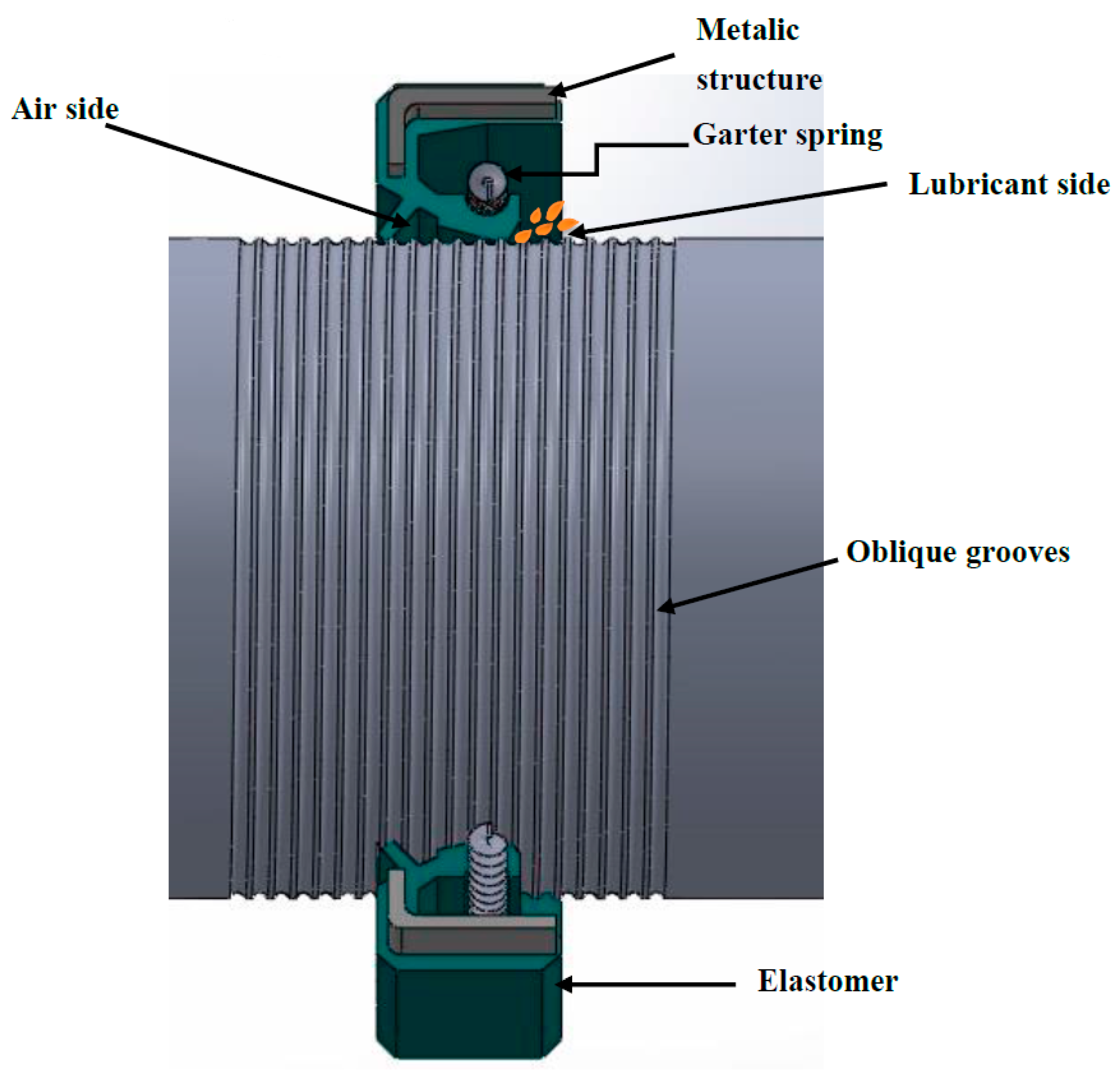
It is known that rotary lip seal is the type of seal widely used in industry for rotating shaft applications, since they represent an efficient and reliable device to retain lubricants and provide a safe sealing mechanism against the entry of external impurities. The nature of the contact between bodies is a key factor of sealing performance. In fact, in previous studies it was shown that good operating conditions of lip seal are reached when a thin lubricating liquid film (a fraction of a micrometer) separates the two surfaces [
1]. This film is generated throughout the asperities in both antagonist surfaces providing a high wear resistance [
2,
3,
4].
Additionally, in order to enhance seal performance, different aspects are involved, such as the surface form, micro-geometry, and surface finish of both shaft and seal. In consequence, the textured surfaces are considered as a relevant technique to increase the load carrying capacity, reduce friction force, and expand the range of hydrodynamic lubrication of the lubricating film of different sealing devices. Different researchers have also integrated this technique in investigations dealing with rotary lip seal in order to improve its functioning. Indeed, in the international literature, various works considered this issue by adopting different groove shapes for the seal [
5] and the shaft with different texture shapes [
6,
7,
8]. In this work, this technique will be adopted by considering a lip seal mounted on an oblique grooved shaft as shown in
Figure 1.
In order to carry out an analysis that describes the complex behavior of a successful lip seal functioning, a hydrodynamic model is required to describe the lubricating film attitude. This analysis is performed numerically, incorporating the fluid mechanics of the lubricating film by solving the Reynolds equation taking into consideration lip surface roughness and the cavitation phenomenon.
This study presents an extensive modeling of the Hydrodynamic (HD) lubrication taking into consideration the relative motion between shaft and lip surfaces, since this investigation has never been treated, to our knowledge, for textured surfaces. Therefore, this investigation uses the finite difference method for the spatial domain and an implicit scheme for the temporal one, as presented in our previous work [
9].
2. Numerical Analysis Using the HD Lubrication Model
In this study, we assume that the rotary lip seal operates under hydrodynamic regime, which means that the load applied in the contact zone is fully supported by the lubricating film. In order to predict the lip seal behavior, a hydrodynamic model is considered. This model deals with the determination of the important lip seal operating characteristics, such as load support, reverse pumping rate, and friction torque. This model reveals the base of the thin film lubrication without taking into account the material’s deformation on the lip surface.
As our seal is fabricated from an elastomeric material, considering the deformation of the lip surface seems to be crucial for lip seal investigations. However, the sealing motion is limited by the centrifugal effects. In fact, a rotating seal generates significant centrifugal forces that can affect the compliance matrices, which then affects the correctness of the numerical results. Furthermore, modeling taking into accounts the centrifugal effect seems to be hard to achieve and, indeed, until now no research has managed to study or find these matrices. Hence, considering HD modeling seems to be convenient to avoid these limitations.
Consequently, in this work, we deal with the hydrodynamic model using an iterative computational procedure. In our model, we assume a full, thin fluid film separating the shaft (which is considered to be perfectly rigid) and the lip. The presence of micro-asperities on both surfaces and finally the lip seal behavior is considered to be completely axisymmetric.
2.1. Hydrodynamic Lubrication
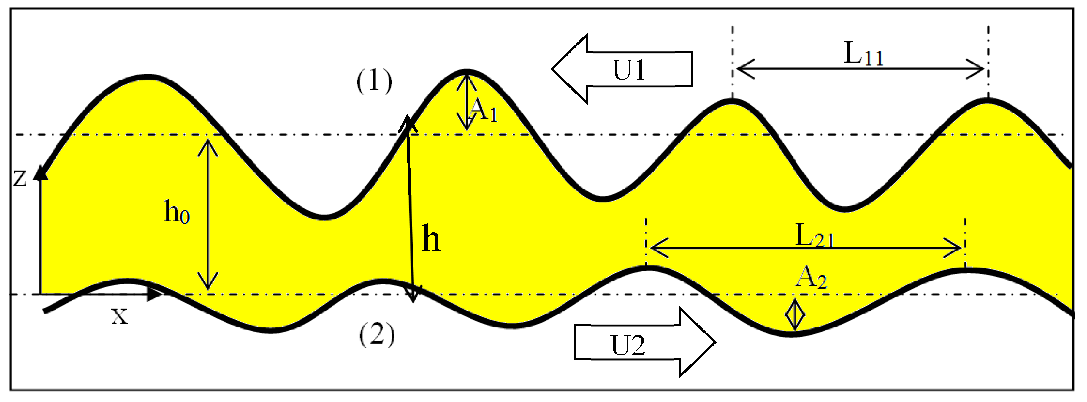
The general differential equation governing pressure distribution in a thin lubricating film for a transient hydrodynamic lubrication model is the generalized Reynolds equation expressed in Equation (1). This equation considers the phenomenon of cavitation which is a result of surface micro-geometry. Therefore, the resolution was performed in the active and non-active zones by taking into account the lip roughness.
: the film thickness illustrated in
Figure 2, where surface 1 represents the lip surface and surface 2 represents the shaft surface. Further,
h1 is the lip roughness,
h2 is the shaft roughness, and
h0 is the average film thickness.
In the cavitation zone (not active):
and:
where
r is the replenishment ratio, ρ represents the gas–lubricant mixture density, and ρ
0 is the lubricant density.
The relative speed of the lubricant is U = U1 + U2, where U1 is the lip speed and U2 is the shaft speed.
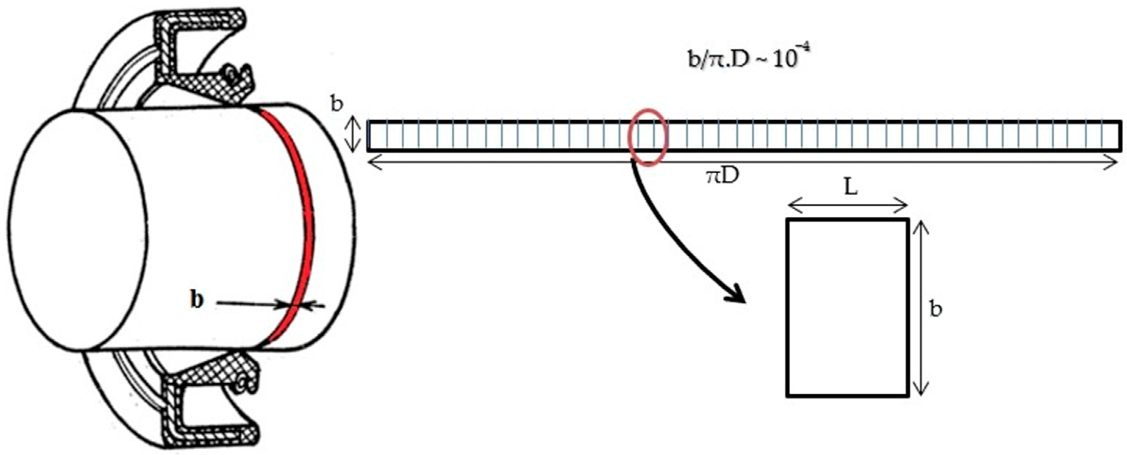
The lip roughness is considered periodically distributed along the
x-direction with a period cell
L. Through this periodicity, it is possible to simplify the calculation domain to one cell having
L as length and b as width according to the circumferential direction [
9] as shown in
Figure 3. Then we deduce the boundary conditions to be applied as follows:
where ps is the lubricant side pressure and pa is the air pressure.
2.2. Numerical Algorithm
A numerical analysis of the transient isothermal hydrodynamic lubrication was realized using the finite differences method for the spatial domain and an implicit scheme for the temporal domain for the purpose of calculating the hydrodynamic pressure distribution.
The overall algorithm is already represented in a previous work [
9]; nevertheless, in this section, we will validate its results with respect to the international literature in order to show the efficiency of the present approach.
2.3. Validation Code
A validation study is needed to justify the performance and the accuracy of our model. For that reason, a comparison was made between the present model and the numerical results found through the finite volume method performed by Shen [
10].
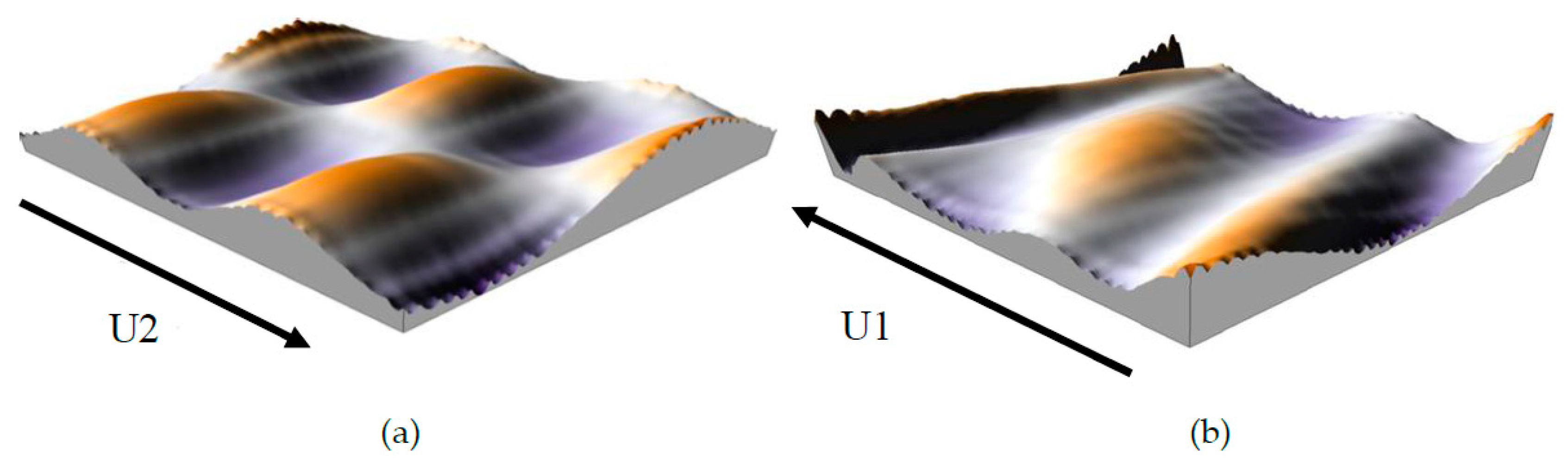
2.3.1. Numerical Modeling
Before discussing the effect of surface texturing on the lip seal operating, it is necessary to clarify the validity of the adopted numerical model for rough surfaces. A primary approach was adopted in defining the roughness of the shaft and the lip by considering double sinusoidal functions. These surfaces are similar to those described by Shen [
10] (
Figure 4).
Our system is composed of a stationary rough seal and a moving rough shaft with a relative speed
U2 in the
x-direction (
Figure 4a). The shaft surface
h2 is defined by the expression in Equation (5).
where
A2 is the shaft amplitude,
L21 is the shaft asperity number throw
x axis,
L22 is the asperity shaft number according to
y-direction.
L is the lip wavelength according to the circumferential direction.
Furthermore, the lip roughness
h1 is defined by a double-sinusoidal function (
Figure 4b) having the following expression:
Likewise:
L11 is the lip asperity number throw on the
x axis,
L12 is the asperity lip number according to the
y-direction.
A1 is the lip roughness amplitude and
cg is the circumferential shear deformation of the lip, which depends on the lip geometry and the location of the garter spring [
10], with
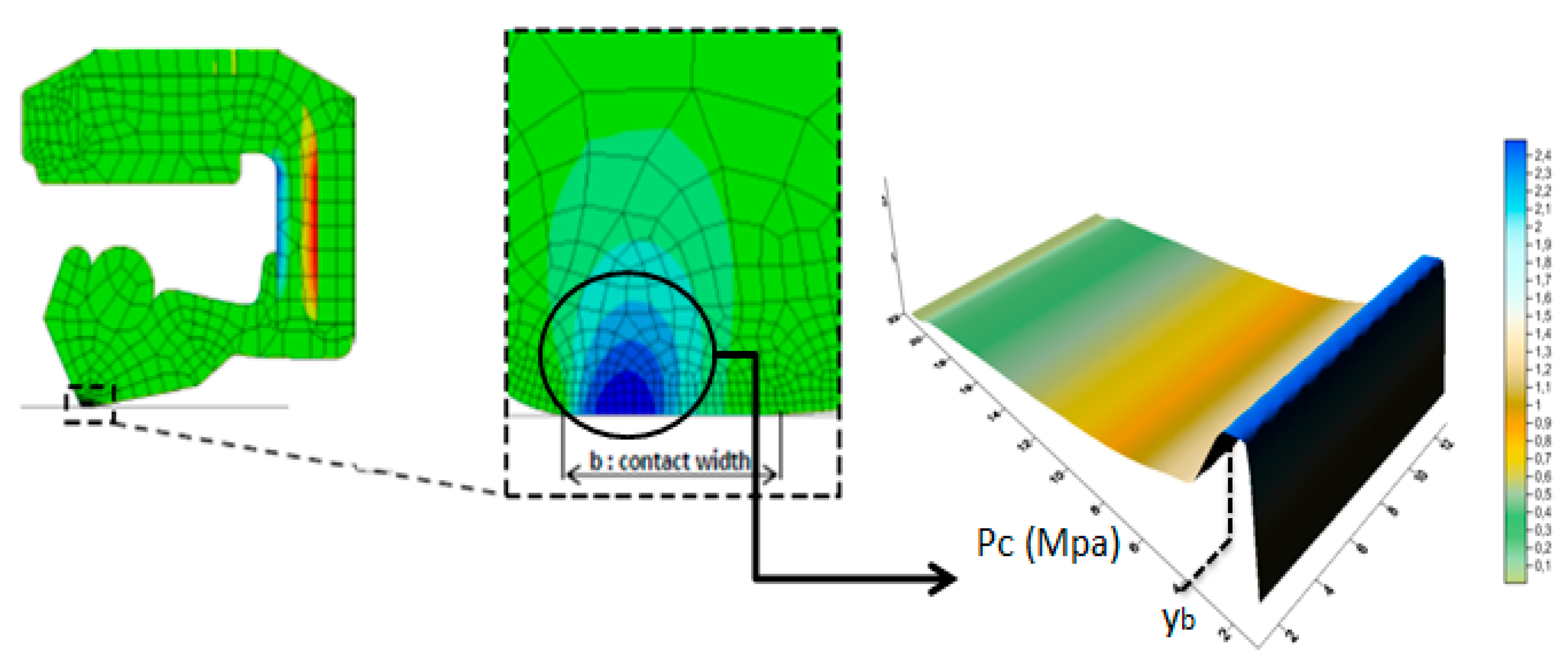
where
yb represents the location of the maximum dry contact pressure (results of structural analysis with the commercial simulation software Abaqus, as presented in references [
6,
11]), as illustrated in
Figure 5.
2.3.2. Comparison of Numerical Results between the Finite Volume and the Finite Differences Method
In this section, the parameters considered are similar to Shen’s work [
10]. The lubricant rheological properties (dynamic viscosity and density) are supposed constant across the film thickness, and we assume the following parameters:
b = 0.5 × 10
−4 m,
L = 0.5 × 10
−4 m,
h0 = 1 × 10
−6 m, μ = 2.5 × 10
−2 Pa·s,
pa =
ps =1.02 × 10
5 Pa,
A1 = 0.5× 10
-6 m,
L11 =
b,
L12 =
L,
L22 =
b/2,
L21 =
L/2,
yb = 3
b/4,
U1 = 0 m/s,
U2 = 4 m/s,
U =
U1 +
U2.
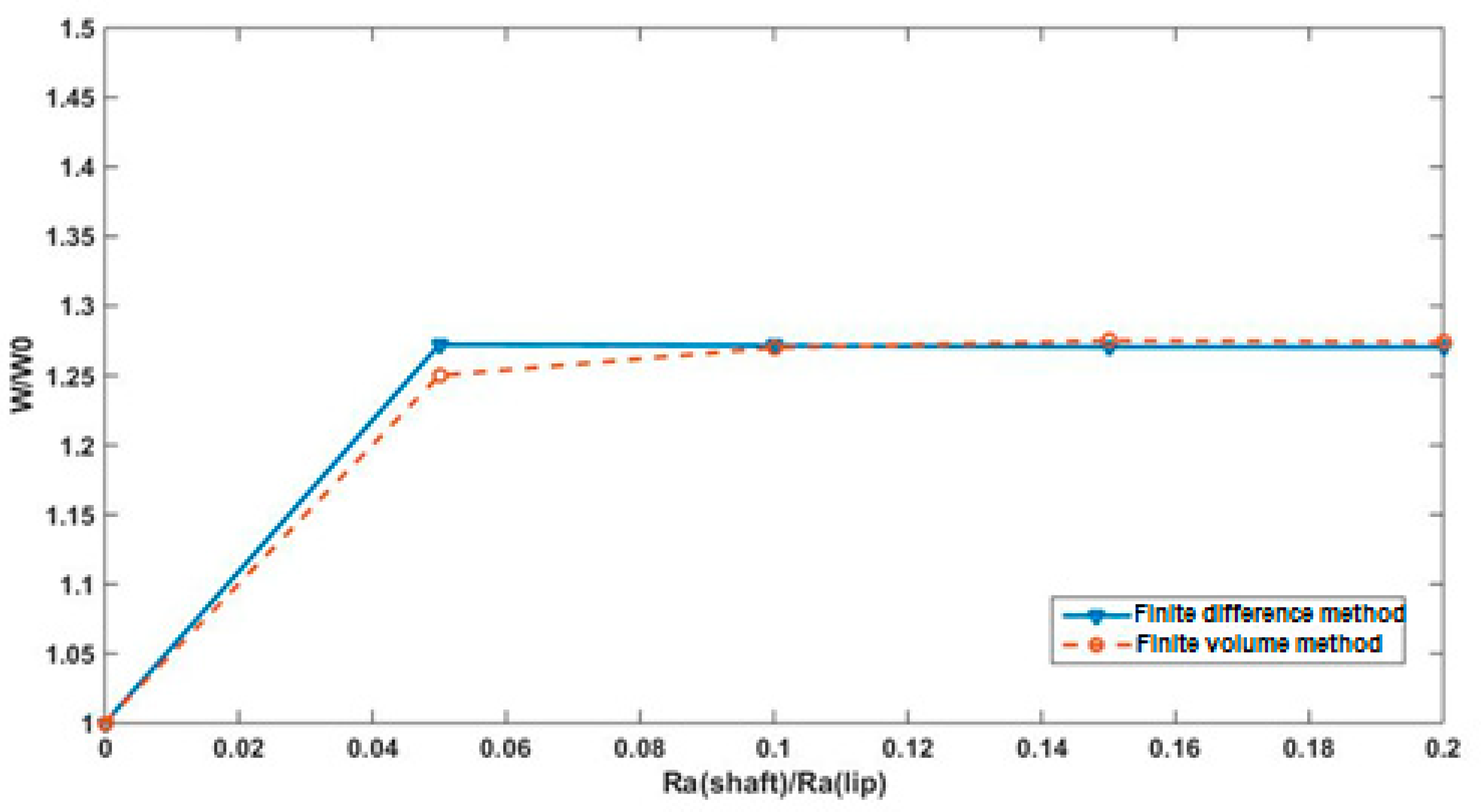
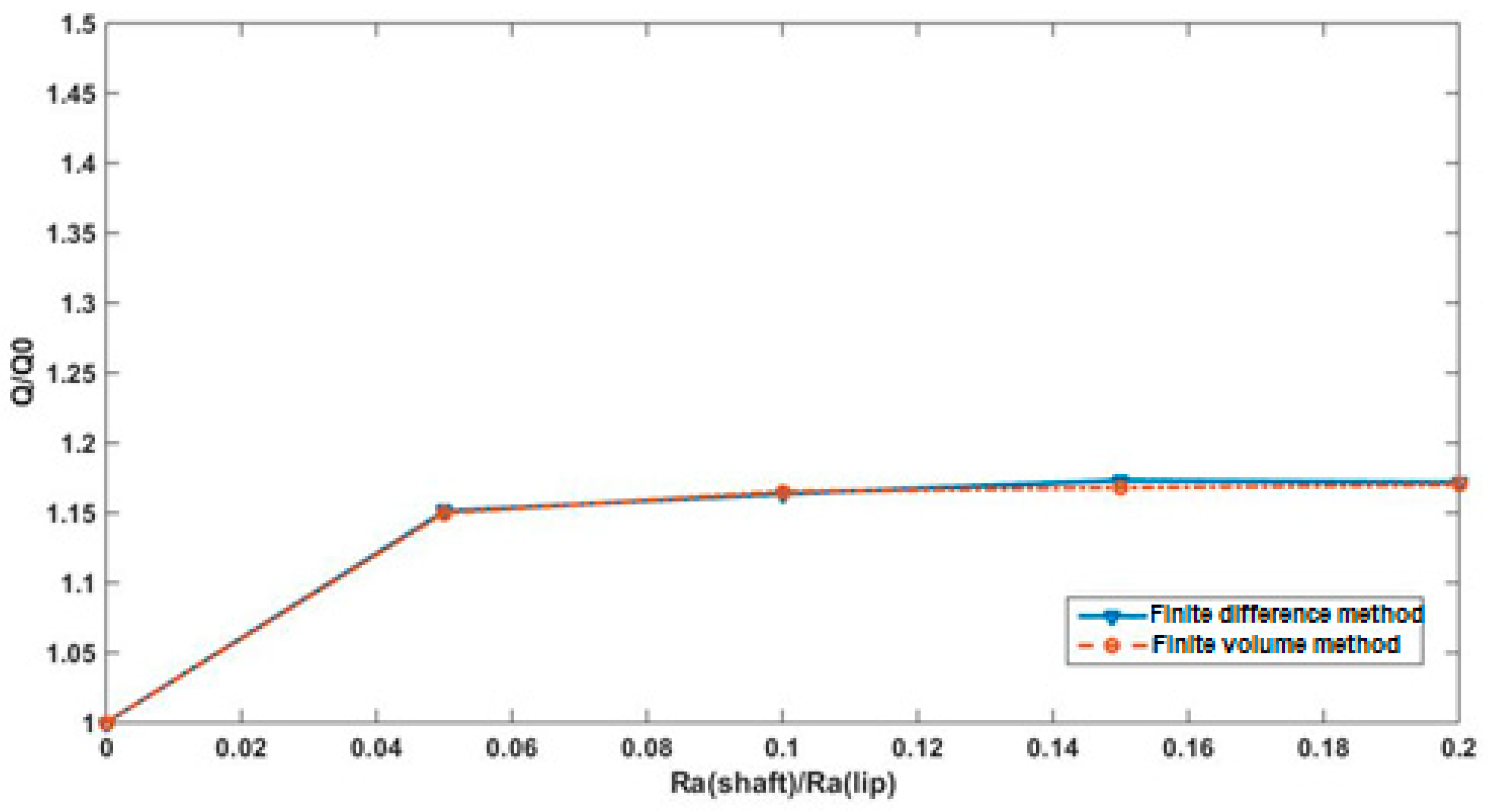
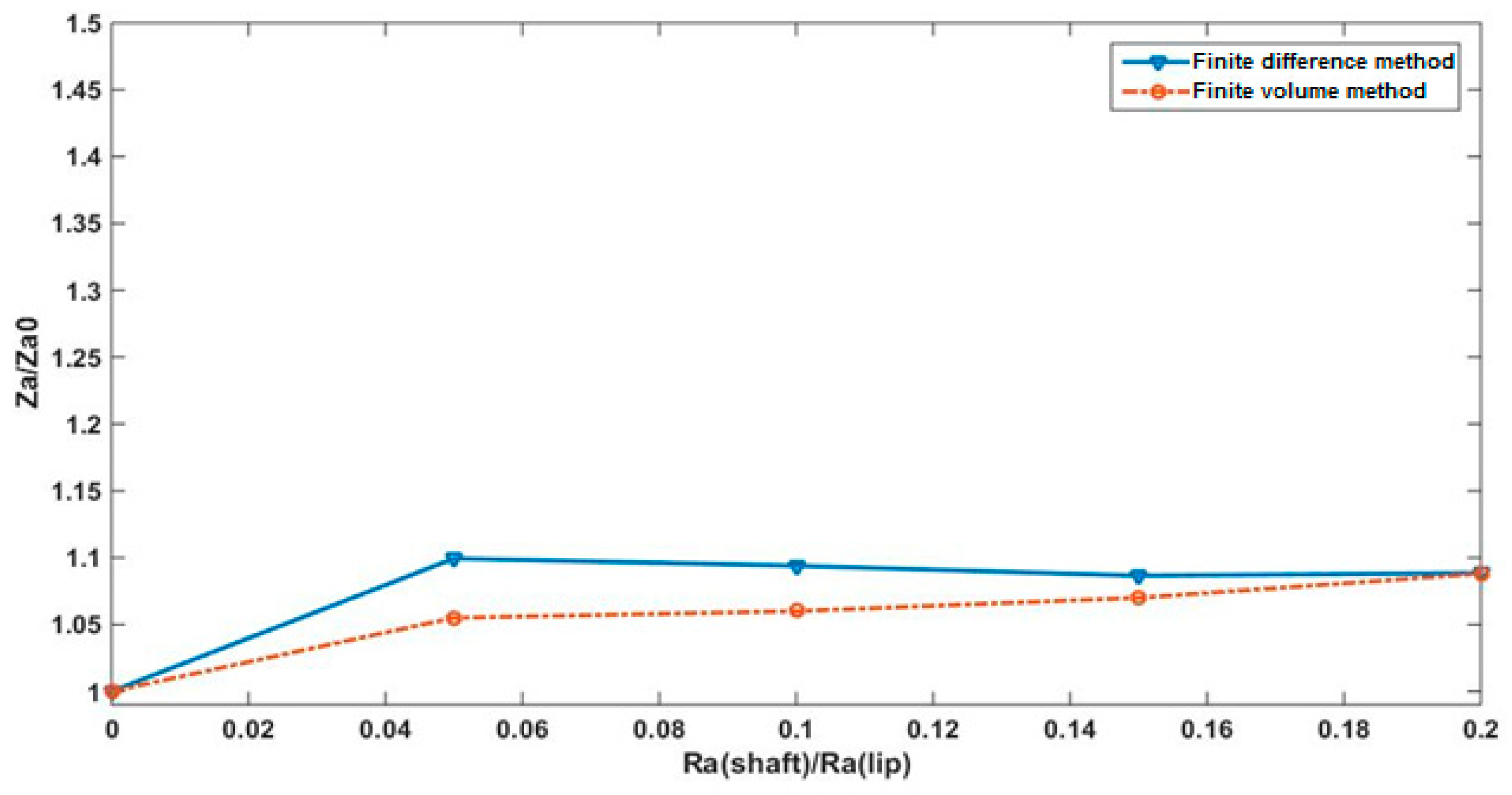
Figure 6,
Figure 7 and
Figure 8 show the effect of the shaft roughness on the performance of the lip seal. The load support, the reverse pumping rate, and the active zones rate increase when the shaft roughness increases. These results prove the correctness of our program. We find that the difference between our method and the finite volume method performed by Shen [
10] is 0.37% for the load support, 0.6% for the reverse pumping rate, and 2.4% for the active zone ratio.
3. Functions of Surface Textures
An implementation of previous validated code was done through the integration of textured surface. Referring to previous researches, textures can significantly improve seal performance and durability in terms of load carrying capacity, wear resistance, friction, and face temperature. Jia et al. [
7] and El Gadari et al. [
6] proved that shaft grooves are an efficient and feasible method to control seal leakage.
Thus, in this section, a comparative study is presented between a transient hydrodynamic model, a transient elasto-hydrodynamic model [
6], and experimental results [
7] examining the groove depth impact on the pumping rate.
3.1. Texture Design
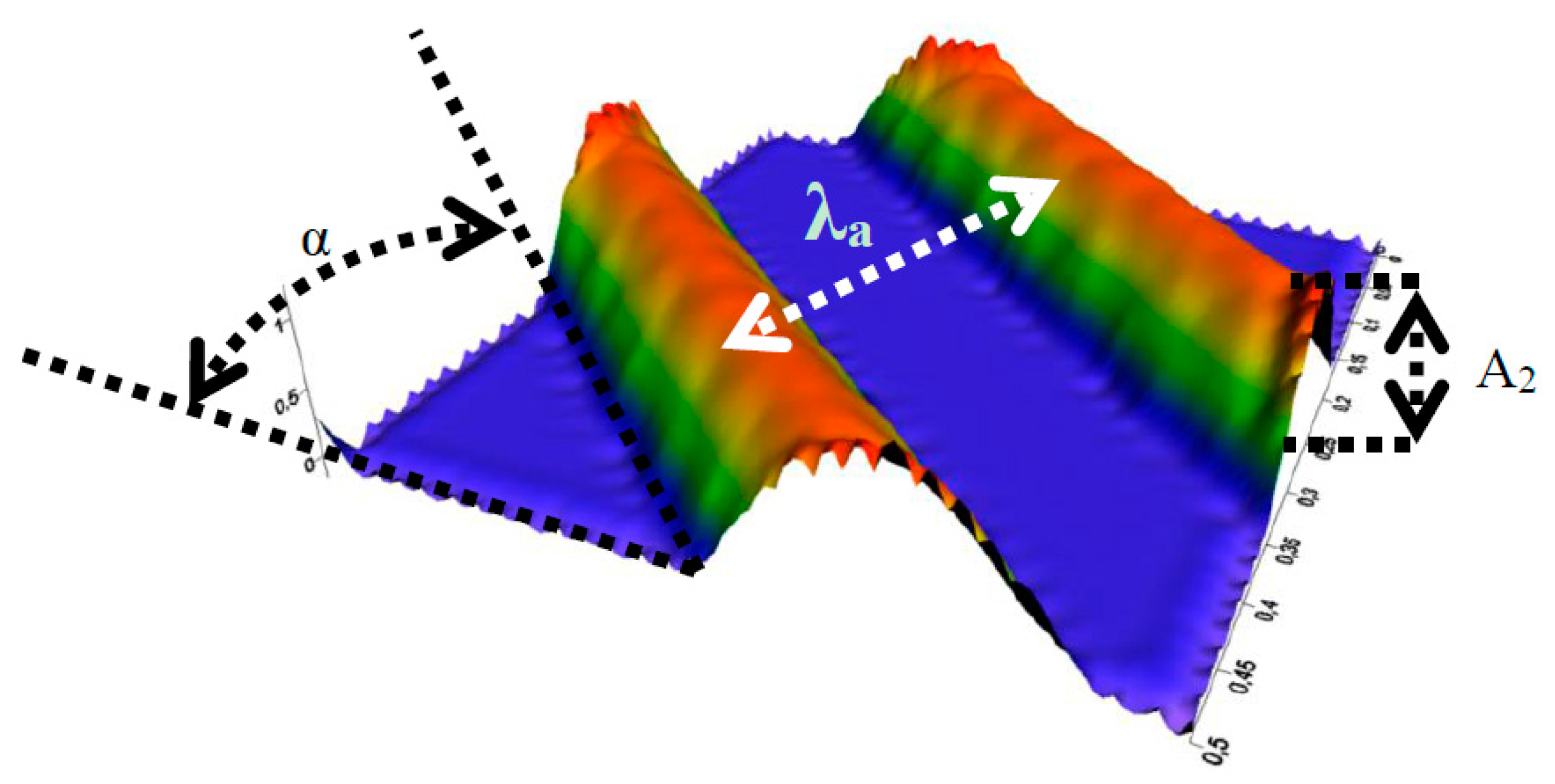
To perform this study, an oblique groove shape was considered. This shape was proposed by different researchers and the model was already manufactured. The oblique grooves were simulated firstly by Jia et al. [
7] in the study of rotary lip seals; however, they did not consider lip roughness. El Gadari et al. [
6] elaborated an entire parametric study dealing with different shapes of rough lip seal surface. It has been proven numerically and experimentally that oblique grooved surfaces generate substantial pumping.
The grooved shaft surface (
Figure 9) is expressed by two-dimensional cosine presented by Jia et al. and El Gadari et al. [
6,
7] defined by the function in Equation (8):
where | | is the absolute value,
A2 is the groove depth,
U2 is the shaft surface speed and
is the shaft wavelength defined by
where,
NG is the groove number in the direction of
x-axis,
R is the shaft radius, and α is the groove angle.
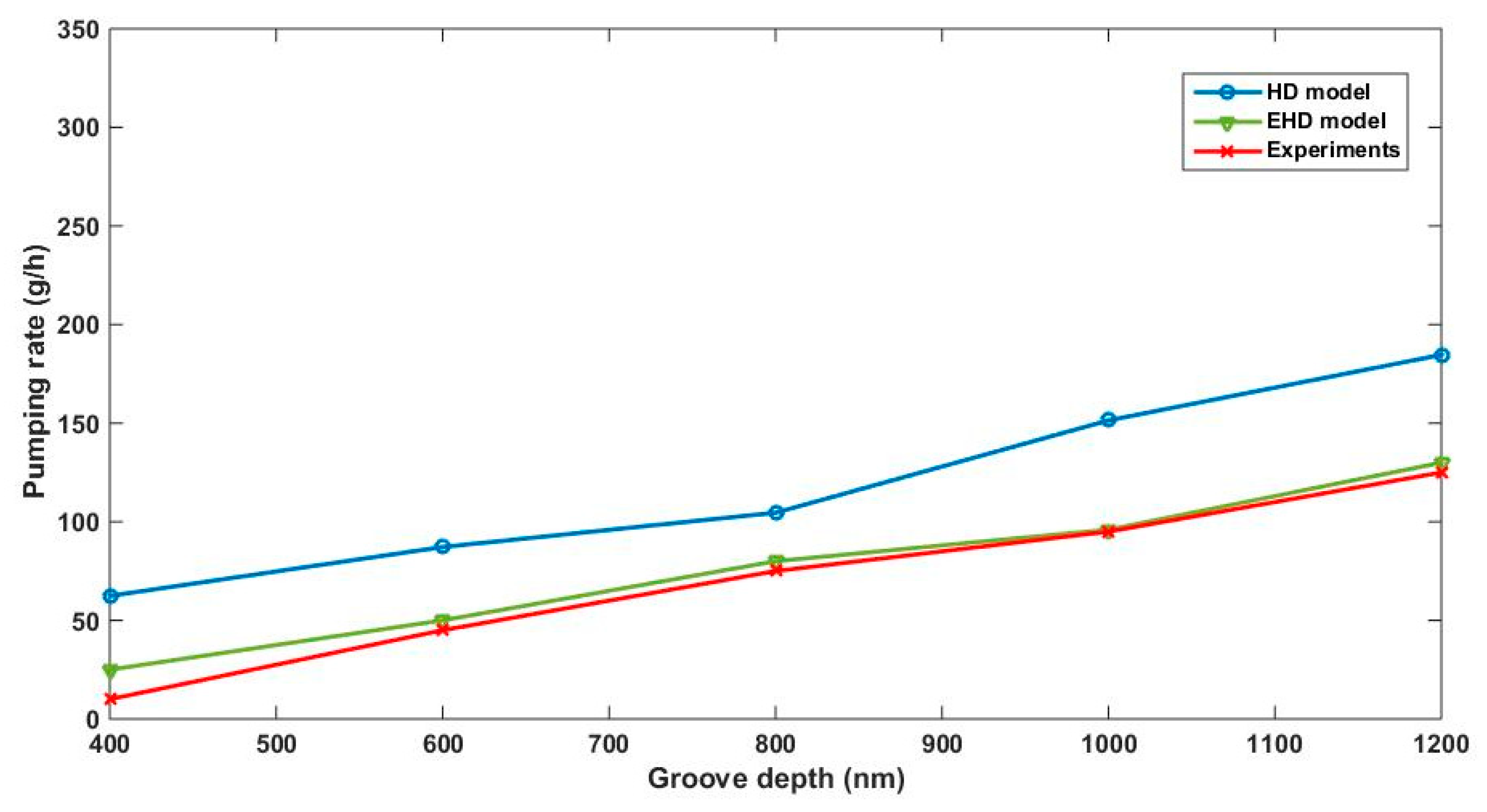
3.2. Comparison of the HD Model with the EHD Model and Experimental Results
In order to evaluate our results and to show the validity and the reliability of the HD model, a comparison was made between our model’s results, the Elasto-HydroDynamic (EHD) model’s results found by El Gadari et al. [
6], and the experimental results presented by Jia et al. [
7]. The EHD model is based on the coupled analysis of fluctuations in the lubricant pressure by using fluid mechanics theories and the elastic deformation in normal and circumferential directions of the seal.
The adopted surfaces for this section are a stationary rough lip surface
h1 and a moving textured shaft surface
h2 (defined by Equation (8)). The expression for
h1 is:
The adopted parameters are similar to both cited studies [
6,
7], and these parameters are: shaft radius
R = 40 mm, shaft speed
U2 =
RΩ (where Ω = 2000 rpm), lip speed
U1 = 0, contact width
b = 0.12 mm, The study domain’s length
L = 0.2 mm, Lip surface wavelength in
x and y directions
L11 =
L and
L12 =
b/3, lip surface amplitude
A1 = 1 μm, wavelength in the circumferential direction λ
a = 0.2 mm, lubricant dynamic viscosity (at 2000 rpm) μ = 0.0336 Pa·s, groove angle α = 25°, and groove density
NG = 2500. Subsequently, the effect of the groove’s depth on the reverse pumping rate is examined.
Figure 10 shows that, on the one hand, the reverse pumping rate increases by considering higher values of the grooves depth—higher than the shaft roughness (experimentally measured, which is in the order of 90 nm according to the results obtained by El Gadari et al. [
11].
On the other hand, there is a slice shift between the HD and EHD models and the experimental results. However, the layout of the graph of our model has the same shape as the experimental one and shows that effectively, the reverse pumping rate increases corresponding to the groove depth, which shows that the HD model describes well the behavior of the rotary lip seal. We can conclude that the HD model represents a beneficial approach to describe the functioning of our seal without considering the elastic behavior of the lip. Consequently, we lift the EHD limitations previously cited and show that this model reduces time and effort generated by including the study of deformation.
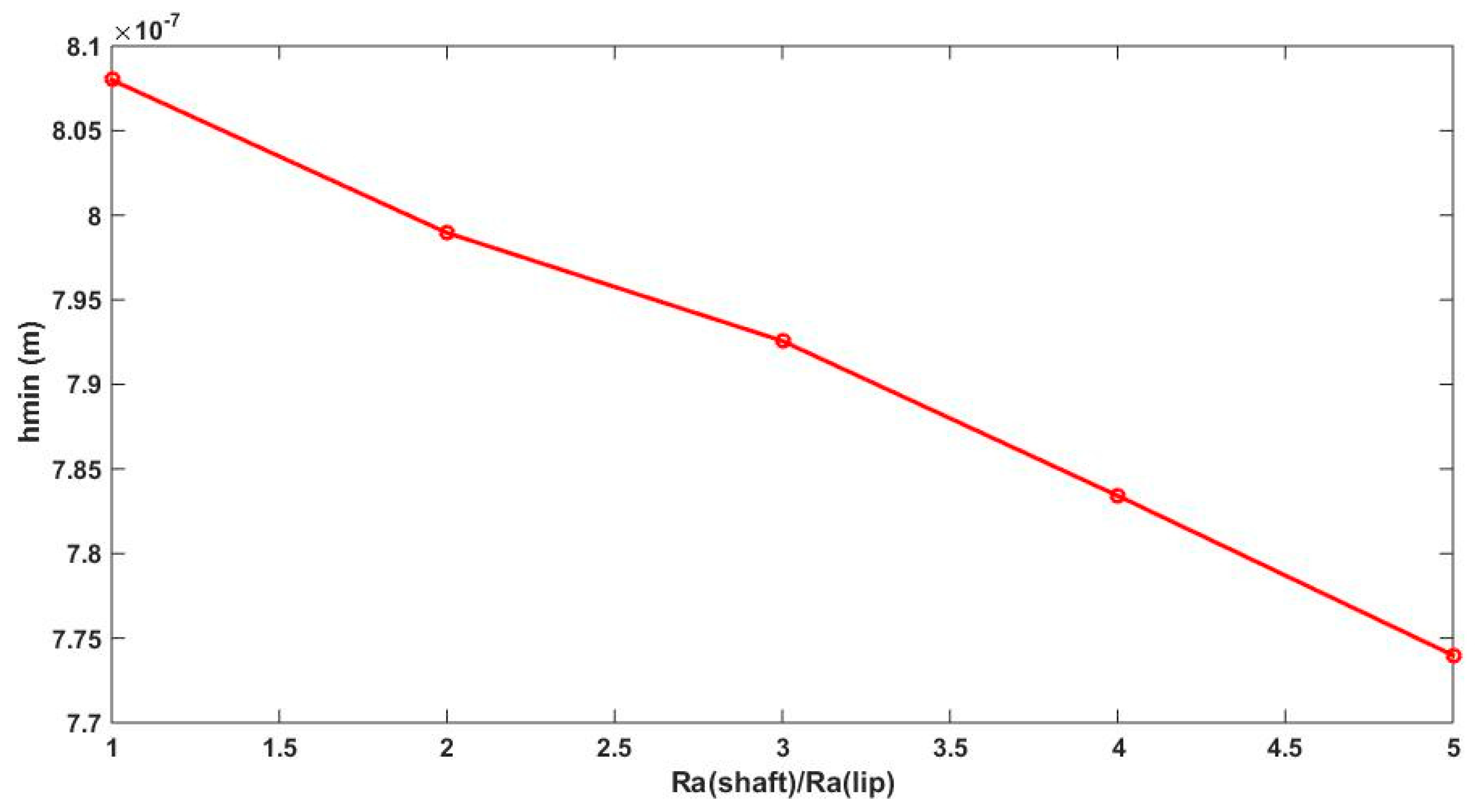
4. Effect of Relative Motion
In this study, in order to explore the effect of the shaft and the lip relative velocity on the hydrodynamic parameters, the roughness of the lip was considered, and the shaft surface was considered as a textured surface.
In this investigation, we dealt with an oblique groove form for the shaft surface (Equation (8)), and the groove angle was taken for α = 25°, and the groove number in the direction of the x-axis equaled 4000. Furthermore, the lip roughness considered is the one expressed by Equation (6) and we assume L11 = b, L12 = L, b = 0.5 × 10⁻⁴ m, L = 0.5 × 10⁻⁴ m, h0 = 1 × 10⁻⁶ m, μ = 2.5 × 10⁻² Pa·s, pa = ps = 1.02 × 10⁵ Pa, and A1 = 1 μm.
With the present considerations and before presenting the different relative motion cases, we can compute the minimum film thickness
hmin.
hmin is the smallest separation between lip and shaft surfaces and thus the most critical, since it characterizes the lubrication regime. Simulation of the minimum film thickness as a function of shaft arithmetic roughness is shown in
Figure 11.
We note from
Figure 11 that when the minimum film thickness is higher than zero it means that this separation is sufficient to make asperity interaction negligible, and the condition of hydrodynamic lubrication is verified; the values are in the order of micron, which justifies the nomination of thin film lubrication. Finally, the graph shows that
hmin reduces by increasing the shaft arithmetic roughness.
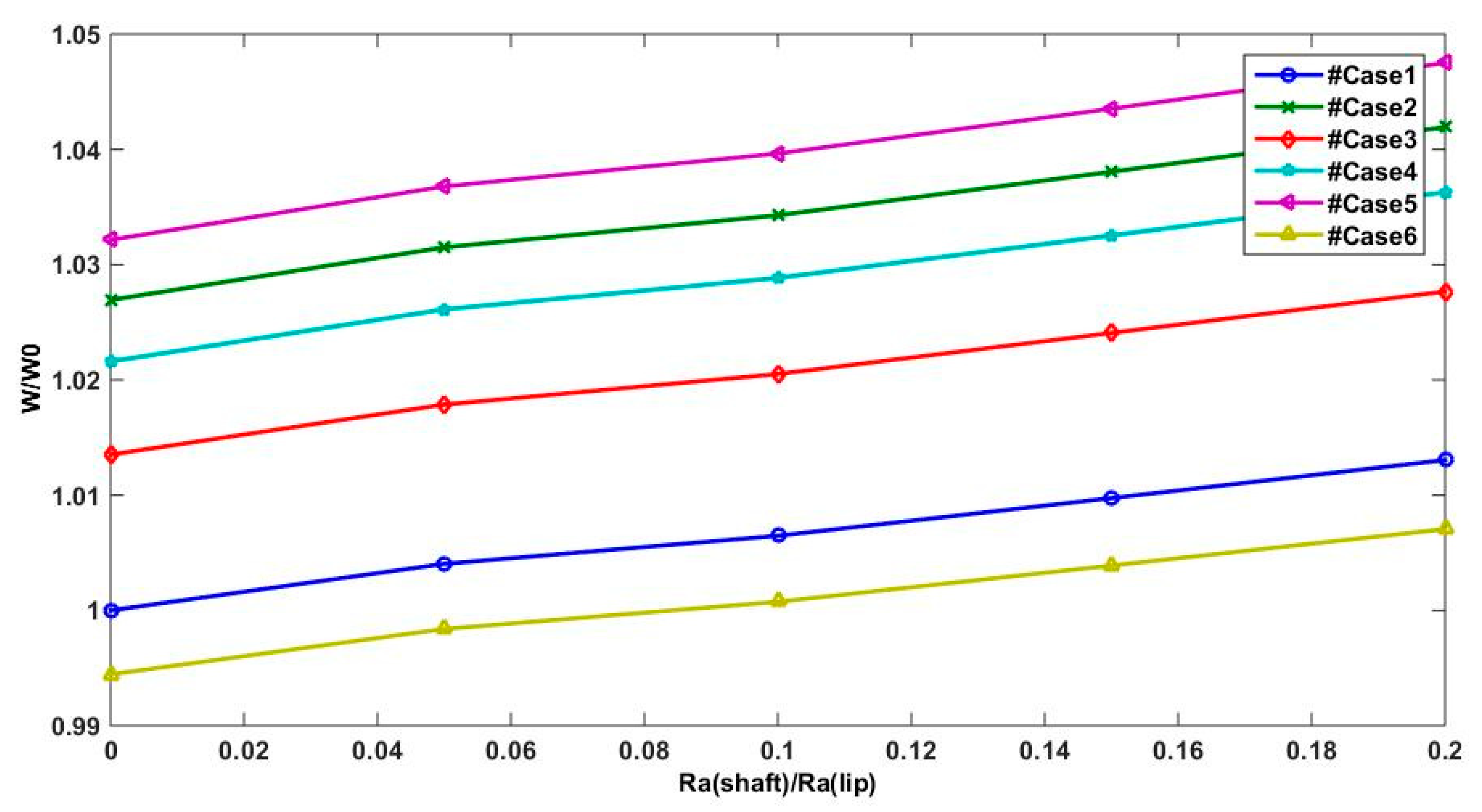
All in all, six cases of relative movement were examined, assuming that for the six cases, the relative speed remains the same, and we assume . The six cases are:
stationary shaft and moving lip (case 1):
standard case, where the shaft is rotating and the lip is stationary (case 2):
both surfaces are moving symmetrically in different directions (case 3):
shaft is moving faster than the lip (case 4):
both surfaces are moving symmetrically in a positive direction (case 5):
both surfaces are moving symmetrically in a negative direction (case 6):
To consider the motion of the two surfaces, we consider the Reynolds equation (Equation (1)), taking into account both lip and shaft motion. For this consideration, the load support and the reverse pumping rate remain the same; however, the friction torque formula changes and becomes:
The non-dimensional lifting force W/W0, leakage ratio Q/Q0, and friction torque C/C0 were examined throughout their averaged values in one period (Equation (12)), where Q0, W0, and C0 define the parameters for Ra(shaft) = 0 related to case1.
The variation of the different parameters describing the lubrication film behavior is evaluated through the variation of the shaft and lip arithmetic roughness and this variable is given by the following expression:
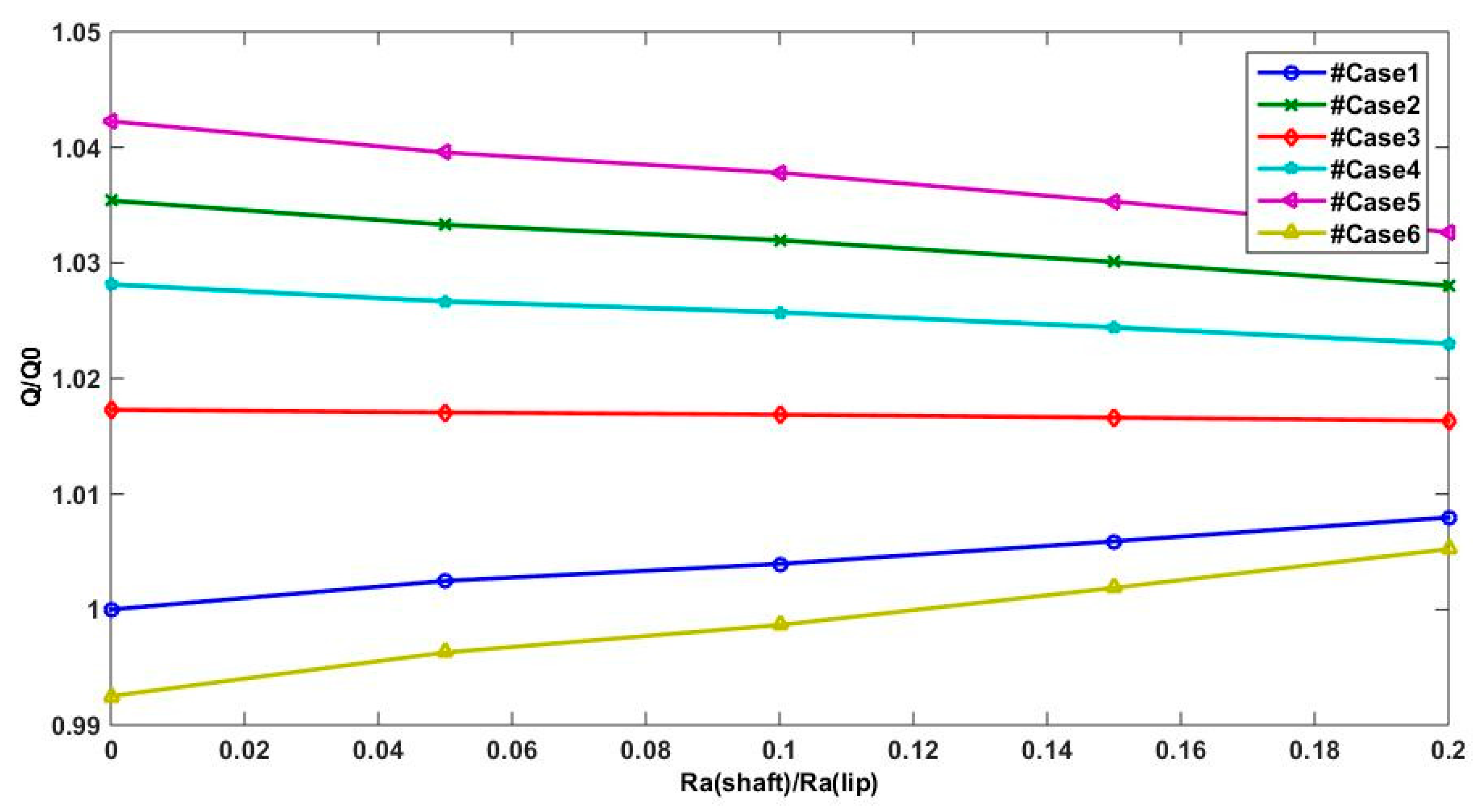
Figure 12 and
Figure 13 show the effect of the relative velocity between lip and shaft surfaces on lifting force and reverse pumping rate. The two parameters (
W and
Q) are estimated when the shaft and lip surfaces are moving in a positive direction and the shaft speed is higher than the lip speed (case 5) and also For case 2 when only the shaft motion is considered. However, for the case 1 and case 6 when the shaft motion is not considered (
U2 = 0) or the lip speed is higher than the shaft speed (|
U2| < |
U1|), we can note that the reverse pumping rate and the lifting force are underestimated compared to other cases. This result confirms that shaft motion is essential to generate substantial hydrodynamic pressure.
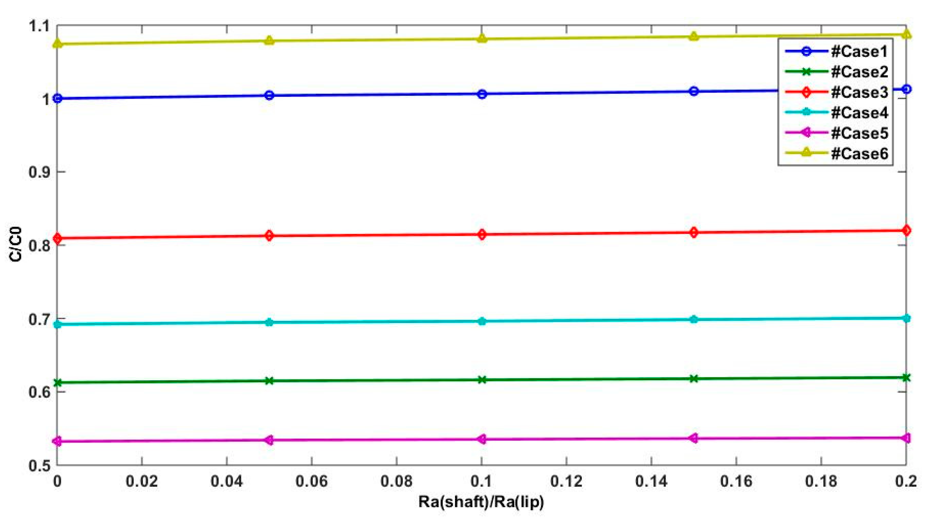
The friction torque in shaft surface is more significant when the lip surface speed is higher than the shaft surface speed or when only the lip surface is moving (cases 6 and 1, respectively) as presented in
Figure 14, compared to the other cases when the shaft motion is more important than the lip movement.
The obtained results allow the conclusion that shaft motion is substantial in providing a good lip seal functioning, since it assures a good reverse pumping rate and an important support load and finally a low friction torque. In fact, manufacturers could exploit these results and think about systems where the lip seal is moving in the same direction of the shaft surface with a higher shaft speed.
5. Conclusions
A numerical investigation was carried out using the hydrodynamic model. This study was elaborated by considering a grooved shaft and six cases of relative motion between lip and shaft: the lip moving while the shaft is stationary, the shaft moving and the lip is stationary, the lip and shaft are moving with same velocity but in different directions, the lip and the shaft are moving in positive and negative directions, and the shaft and the lip are moving with different speeds in the same direction.
The results introduced in this work have shown that, firstly, the hydrodynamic model, even if it is a basic approach, describes confidently the thin lubricating film behavior. This was proven through the comparison of this model’s results, those found experimentally, and Elasto-HydroDynamic ones.
Secondly, the grooved shaft influences the lip seal functioning, since it enhances the reverse pumping rate then reduces lubricant leakage by considering higher groove depth. That elucidates the strong impact of surface texture in boosting the radial lip seal performance.
Finally, it has been shown that the presence of relative motion between the shaft and the lip surfaces alter the performance of the hydrodynamic lip seal. Therefore, the seal behavior was described in terms of the effectiveness in improving load support, friction, and leakage in relation to the relative motion. The overall significance of the presented results lies in the assumption that grooved shaft motion is mainly crucial for a performing rotary lip seal when the shaft rotates at a higher speed than the lip.
