Article

Simulation of a Steel-Aluminum Composite Material Subjected to Rolling Contact Fatigue

Institute of Machine Design and Tribology, Leibniz University Hannover, Welfengarten 1A, 30167 Hannover, Germany
*
Author to whom correspondence should be addressed.
Lubricants 2019, 7(12), 109; https://doi.org/10.3390/lubricants7120109
Submission received: 30 October 2019 / Revised: 22 November 2019 / Accepted: 2 December 2019 / Published: 6 December 2019
(This article belongs to the Special Issue Selected Papers from the 60th German Tribology Conference 2019)

Abstract

:
Rolling bearings are frequently used machine elements in mechanical assemblies to connect rotating parts. Resource efficiency and reliability enhancement are considered to be important factors of rolling bearing development. One of the ways to meet these requirements is the tailored forming (TF) technology, which enables the functionalization of several metal layer composites in a single component. The so-called hybrid machine elements can be produced by co-extrusion of aluminum and steel and subsequent die forging, heat treatment, and machining. The TF rolling bearings made by this process can provide optimized characteristics that use aluminum to reduce weight and steel for a highly loaded contact zone between a rolling element and a bearing raceway. To evaluate the applicability and the potential of this technology, theoretical investigations are presented in this paper. The stress distribution under fully flooded conditions, caused by an external load in the contact between a rolling element and the TF outer ring of an angular contact ball bearing, is analyzed statically with the finite element method. The fatigue life of the TF component can be calculated for different external axial loads and manufacturing parameters, such as steel-to-aluminum volume ratios and osculation. As a damage model, the Ioannides and Harris fatigue model and the Dang Van multiaxial fatigue criterion were used. The results show that the fatigue life has high sensitivity to the steel-to-aluminum volume ratio. For the hybrid component with a steel layer thickness of 3 mm, 90 percent of the fatigue life of pure 100Cr6 steel bearing bushings is reached. In this FE model, residual stresses due to machining processes can be regarded as an initial state, which can increase the fatigue life of this TF machine component.

Graphical Abstract

1. Introduction

With the current technology development in the engineering field, mechanical parts are designed in consideration of material properties and operating conditions. However, some mechanical elements that must withstand high loads, such as rolling bearings, still require further development to improve high performance in specific applications. High loads in rolling bearings under continuous cyclic motions can lead to wear or rolling contact fatigue (RCF) depending on operation conditions [1,2,3]. One possible approach to reducing those failures while reducing weight is to design machine elements made of two different metals with suitable material properties for each application goal. To achieve such hybrid machine elements, a process chain for the joining of two different materials [4], a forging process for the creation of a beneficial joining zone [5] and material properties, an adjusted heat treatment [6], and precise surface finishing are being developed within the Collaborative Research Centre 1153 (CRC 1153). The approach is inspired by the production of tailored blanks [7], which are made of different alloys, material grades, or sheet metal thicknesses. In the present paper, a hybrid mechanical component made through the above process chain was investigated. A combination of aluminum as a bulk material, which reduces the weight, and steel in a highly loaded contact zone of a raceway was examined. In order to calculate the component stress distribution caused by an external load under fully flooded conditions, a linear elastic finite element analysis for static loads was performed. Statistically based and standardized fatigue life calculation approaches were used to predict the fatigue life. Simulations for various loadings and geometric conditions as well as those for exemplary residual stresses conditions were carried out.

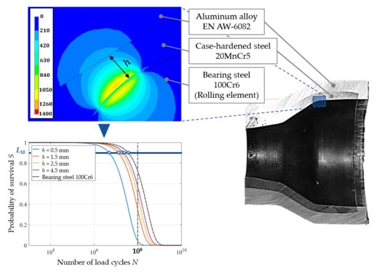
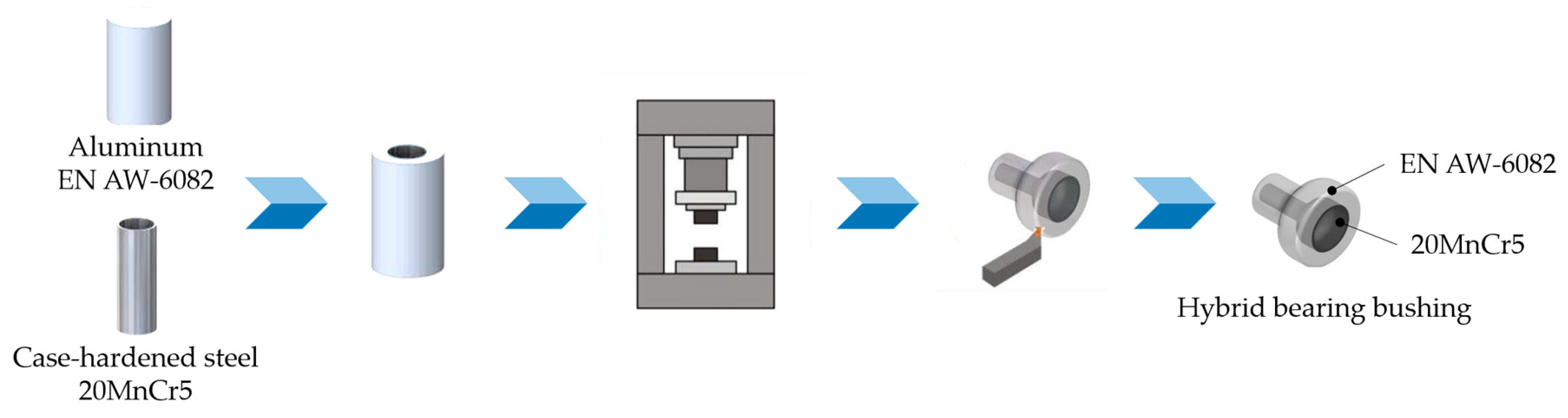
2. A hybrid Angular Contact Ball Bearing Bushing

Rolling bearings are manufactured generally out of high-strength, hardened materials with very high surface quality. For fully flooded conditions, the highest tribological stress, which is responsible for RCF, occurs in a small material volume under the contact surface [8]. The basic design idea for the optimization of rolling elements is that hardened materials are used for highly loaded areas. This can be handled with a combination of different metallic materials through tailored forming (TF). However, the manufacturing of those mechanical elements may pose difficulties, because material properties can be changed due to structural changes or pore formation in heat-affected zones during the production of semifinished products [9]. To take on the challenge, a novel process chain was developed within the CRC 1153 via TF, with which a hybrid angular ball bearing bushing can be manufactured (see Figure 1).
First, a hybrid semifinished workpiece is manufactured by a joining process with two different metallic materials, in this case a high-strength case-hardened steel and an aluminum alloy. For this joining process, improved lateral angular co-extrusion (LACE) [11,12] is used, whereby failures caused by contaminated blocks or by significantly low material temperature in extrusion presses can be avoided. Subsequently, the workpiece is formed by die forging. Heat treatment and machining are carried out to achieve required boundary zone properties for rolling bearing applications. Surfaces of hybrid machine elements can be optimized by surface finishing, which causes residual stresses near the surface [13,14].
In the present paper, a hybrid bearing bushing was investigated as one of the products manufactured in the above process chain. This hybrid bearing bushing was made from an aluminum alloy EN AW-6082 and a case-hardened steel 20MnCr5 (material number: 1.7147), which acted as the outer ring of an angular contact ball bearing. Detailed components of the hybrid angular contact ball bearing bushing are shown in Figure 2.
The 10 rolling elements and the inner ring were made of a classic bearing steel 100Cr6 (material number: 1.3505; AISI 52100) and were taken from a commercially available angular contact ball bearing type 7306 (main dimensions according to DIN 628-1), which have a contact angle of 40 degrees. It can be expected that this TF product provided optimized characteristics with regard to component weight and operational behavior by using locally adapted material properties.

3. Fatigue Life Calculation Based on the Ioannides–Harris Fatigue Life Model and the Dang Van Criterion

To predict the fatigue life of the hybrid bearing bushing, the fatigue life model of Ioannides and Harris [15] was used, which is a standard for fatigue life calculations according to DIN ISO 281 [16]. The Ioannides and Harris fatigue life model is based on the model of Lundberg and Palmgren [17], in which the weakest link theory of the Weibull reliability [18] is applied. Lundberg and Palmgren provided the first theoretical basis for the formulation of a bearing life model considering a particular depth of the maximum orthogonal shear stress and a weak point in a material based on the Weibull theory. In order to overcome some limitations associated with the theory of Lundberg and Palmgren, Ioannides and Harris proposed that the stressed volume is divided into discrete volume elements with the assumption that each volume element has an own probability of failure. The maximum stress is calculated for each volume element and set into correlation with a stress-related fatigue criterion. The stress threshold for the material, below which failure does not occur, is additionally defined. Each element is weighted according to the depth below the surface, and the probability of survival is determined in terms of the integral of each volume element over the stressed volume, shown as follows [19]:
ln ( 1 S ) N e V ( τ i τ u ) c z h d V
where S is the probability of survival, V is the loaded volume, and N is the number of cycles. The dependence of the maximum shear stress z , the stress fatigue limit τ u , and the fatigue stress criterion τ i on the material are taken into account. The term τ i can be determined with a multiaxial fatigue criterion; in this investigation, the Dang Van criterion was chosen [20], which was expressed as:
τ i = τ O , max k hyd · p hyd
where τ O , max is the maximum orthogonal shear stress and the constant k hyd depends on the material properties, which are taken into account. Here, k hyd was calculated in accordance with [21] and had a value of 0.23. According to the Dang Van criterion, the local hydrostatic pressure p hyd was obtained from finite element analysis and was modified by residual stresses. To calculate the fatigue life of the hybrid angular contact ball bearing, the respective material properties of the aluminum alloy and the case-hardened steel are given in Table 1.
The material properties of the bearing steel were defined based on DIN ISO 281 [22], which can be improved through surface finishing processes such as induction and quenching [23,24]. Since the S-N curves, which describe the relation between cyclic stress amplitude and number of cycles to failure (Wöhler curves), for the case-hardened steel and the aluminum alloy have not yet been specified for very high load cycles, each fatigue limit value was estimated with reference to [25]. Here, the cycle fatigue strength and the damage mechanisms of the steel alloy 42CrMo4 and the aluminum alloy EN AW-6082 with high load cycles were investigated experimentally and numerically.

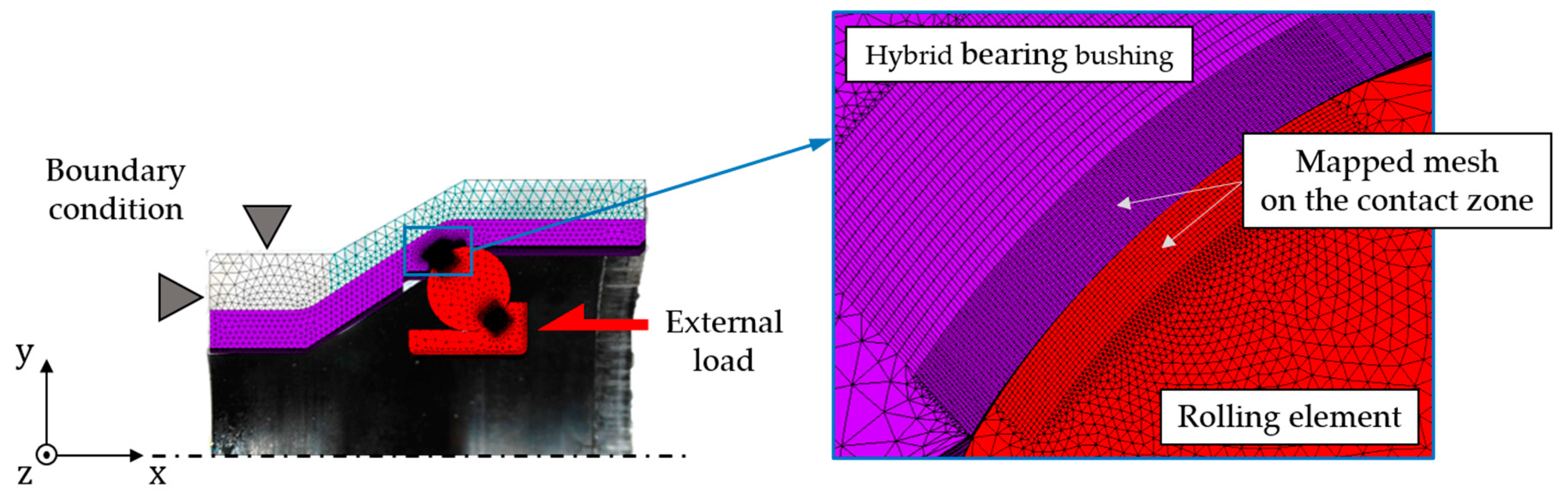
4. Modeling of the Hybrid Angular Contact Ball Bearing Bushing Based on Finite Element Method
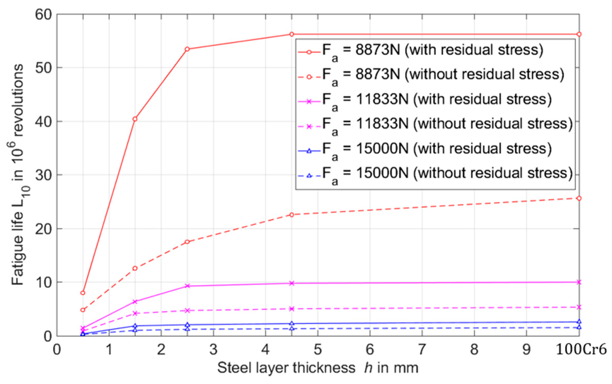
In order to calculate the fatigue life of this hybrid component, a three-dimensional (3D) finite element (FE) model was set up in Ansys Mechanical APDL consisting of the hybrid bearing bushing, the rolling element, and the inner ring (see Figure 3).
For an efficient simulation process, only one contact spot was modeled in a multibody simulation consisting of 36° wide ring segments and a complete rolling element. Three different material properties for each aforementioned material were incorporated in the FE model. For the 3D modeling of all solid structures, an eight-node element (type SOLID185) was used. With this element, volumetric strains at the Gaussian integration points were replaced by an average volumetric strain of the elements (selective reduced integration method). In the loaded zone subject to the rolling contact stress, bending of the volume elements was not expected, so the shear locking modes can be neglected. All the supporting volumes, which were not relevant for the determination of the fatigue life, were free meshed with tetrahedral element geometry. The loaded volume, where the maximum of equivalent and hydrostatic stress occurred, and the areas, where the residual stresses were present, were discretized with a mapped mesh with an element size of 38 μm × 20 μm × 17 μm (length × width × height), as shown in Figure 3. To configure the contact pair, it was necessary to make sure that the contact was set up as a flexible–flexible contact between the rolling element and the inner or outer ring, where the elasticities were adjusted in accordance with the different materials. In addition, the contact pair was defined as a surface–surface contact, in which a contact and a target surface must be set. The contact elements were located on the contact surface of the rolling element, which had four nodes without middle nodes (type CONTA173). For the target surface of the bearing bushing and the inner ring, type TARGE170 was chosen, which had three nodes without middle nodes. In addition, a coefficient of friction μ of 0.015 was assumed in order to represent the fully flooded condition [26,27]. The augmented Lagrange method was used to solve nonlinear contact problems. This parametric FE model enables simulative investigations to be performed with variations of local geometries, such as layer height of the steel or external loads. The locally discretized orthogonal shear stresses, hydrostatic stresses, and equivalent stresses in the contact zone are the main simulation results, which were transferred to a Matlab routine. According to the fatigue life model, the fatigue life was defined as the time until an initial failure occurs (Equation (1)).
The steel layer thickness h was varied between 0.5 mm and 4.5 mm, which corresponded to the layer thickness of the manufactured hybrid bearing bushing (see Table 2). The fatigue life was furthermore calculated for full steel components made only out of 100Cr6, which in the following corresponded to the case of h = 100 Cr 6 . Because of the difference in layer thickness along the surface of the hybrid bearing bushing due to manufacturing, the parameter h was defined as the perpendicular distance between the contact point of the rolling element/hybrid bearing bushing and the interlayer of the steel and the aluminum (see Figure 4).
An additional variation of the axial load F a was carried out, varying from 8.9 to 15 kN on the shoulder of the inner ring, as shown in Figure 4, in which the ratio of a basic dynamic load rating C to an equivalent dynamic bearing load P was considered. These load values were considered high to very high for a conventional angular contact ball bearing under rotating operating conditions. The different residual stress depth profiles induced by the manufacturing process were measured (see Figure 5) and applied to the simulation model as initial stresses.

5. Results

In Figure 6, the distribution of equivalent stresses on the contact zone is plotted for different steel layer thicknesses and a constant axial load of 8.9 kN.
With increasing steel layer thickness h, a decrease of the maximum equivalent stress, which can play a dominant role in subsurface fatigue nucleation [28], was observed. The maximum equivalent stress was reduced by about 0.16 GPa, from 1.25 GPa to 1.09 GPa, which can lead to an increase in the fatigue life. Residual stresses, which were induced after deep rolling (see Figure 5a), can lead to a further reduction of the maximum equivalent stress. Figure 7 shows that the stress level in the contact zone decreased due to residual stresses. This in turn increased the fatigue life of the component according to the underlying fatigue life approach.
The stress values in the contact zone after each simulation were used for the fatigue life calculation using a Matlab routine. The fatigue life can be expressed by nominal bearing life L 10 in millions of revolutions, which is the service life associated with 90% reliability (probability of survival) [16]. The standard applies to a single bearing or a set of apparently identical bearings used under the same operating conditions. Figure 8 shows the nominal fatigue life L 10 of the hybrid bearing bushing due to the variation of the parameters in Table 2.
Here, it was observed that the fatigue life was extended by considering the residual stress state up to two times. For the hybrid bearing bushing, the fatigue life increased with the steel layer thickness to an extent that depended on external loads and material properties. The additional influence of residual stresses on bearing fatigue life was investigated in previous studies, which supported the hypothesis of an extension of fatigue life by means of a beneficial residual stress state [29,30,31]. The slope of the fatigue life curve changed more (referred to as “sensitivity” in this paper), when the axial force was lower, and residual stresses were taken into account. In the range of the steel layer thickness h from 0.5 mm to 2.5 mm, the fatigue life of the hybrid bearing bushing was sensitive to the variation in the thickness of the steel layer. In the case of low thicknesses of the steel layer, the material volume was subjected to a higher rolling contact stress, which is shown in Figure 9.
At lower thicknesses of the steel layer, a volume with high damage risk in the aluminum layer of the hybrid bearing bushing can be observed (grayed out), because the stress exceeded the material the specific fatigue limit of the aluminum alloy. For h = 4.5 mm, it can be seen that the equivalent stress distribution due to an external load of 8.9 kN in the aluminum alloy was not critical for the fatigue life of this material. However, the elastic deformation behavior of the hybrid bearing bushing occurred at different positions due to the variation of the steel layer thickness; in addition to the risk caused by the loaded tribological contact zone, this can lead to a reduction of the probability of survival of this hybrid component.
With regards to the focus of this investigation, which was set on the higher material thickness values h of 2.0 mm, Figure 10 shows the ratio of the fatigue life of the hybrid component in dependence on the variation in steel layer thickness to the fatigue life of the steel bearing bushing.
In the case of a constant axial load of 11.8 kN with residual stress, the fatigue life of the hybrid bearing bushing can reach 90% of the steel bearing bushing L10 with a steel layer thickness h of only 2.4 mm. This corresponds to a weight reduction of 45% compared to that of the steel component ( m 100 Cr 6 = 1.282   kg ). Assuming no residual stresses, 90% of the fatigue life of the steel bearing busing can be reached with a steel layer thickness h of 3.0 mm.

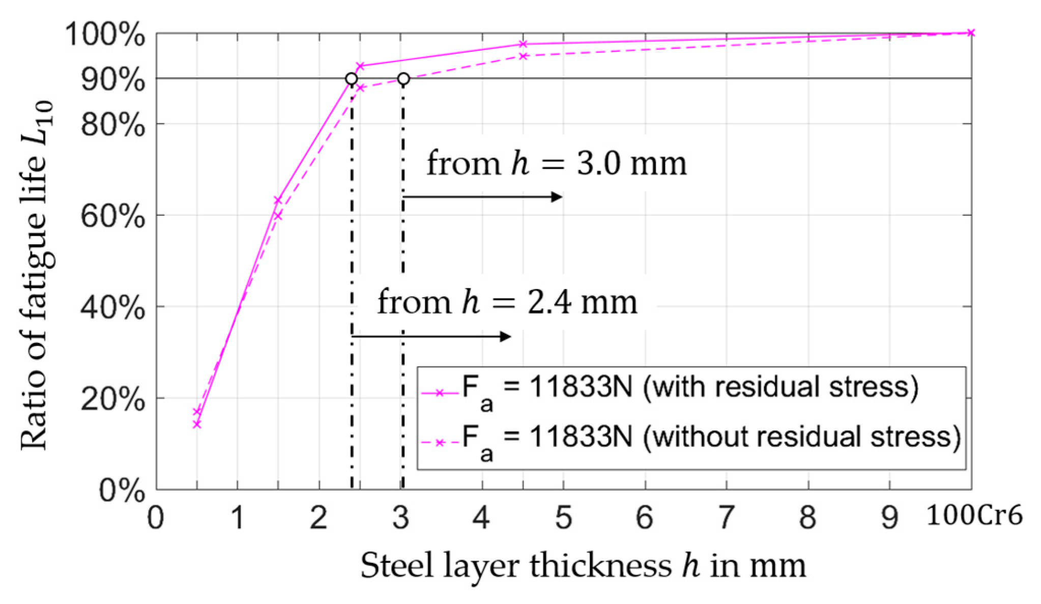
6. Conclusions and Future Work

In the present paper, a theoretical investigation of a hybrid bearing bushing manufactured in the framework of the CRC 1153 was presented. The Ioannides and Harris fatigue life model and the Dang Van multiaxial critical criterion was used for the fatigue life calculation by means of a 3D FE simulation depending on various parameters. The results of the investigation showed that the fatigue life of the hybrid bearing bushing significantly depended on the production parameters. The results of this investigation showed that the fatigue life of the bearing bushing was sensitive to the following parameters:
  • steel layer thickness (for low h values);
  • external load (for low F values);
  • compressive residual stresses (if they were considered).
External load, steel layer thickness, and residual stress play dominant roles in the location of the maximum material stress. As shown in Figure 9, the steel cladding acted as a stress shield for the aluminum layer and increased the fatigue life of hybrid components. With these results, it can be assumed that the fatigue life of the hybrid bearing bushing changes more considerably if the maximum of the equivalent stress is located closer to the contact surface. Therefore, it can be assumed that the fatigue life of the hybrid bearing bushing is sensitive to the location of the maximum reference stress. This investigation provides important basics for the design of hybrid components according to specified requirements.
In order to calculate the fatigue life of this TF component, the FE model can be modified in detail by the submodel technique, so that the influence of the interlayer between the case-hardened steel and the aluminum alloy can be taken into account. It will be also necessary to examine the fatigue limit stresses for the aluminum alloy and the case-hardened steel. In addition, an experimental validation is required at a component level of the calculated fatigue life.

Author Contributions

J.-I.H. and T.C. wrote this article, designed and performed the simulations, and analyzed the results. F.P. and G.P. supervised the work, discussed the basic design of the simulations and provided suggestions for the final discussion.

Funding

This research was funded by the Deutsche Forschungsgemeinschaft (DFG, German Research Foundation), grant number 252662854.

Acknowledgments

The results presented in this paper were obtained within the Collaborative Research Centre 1153 for the subproject C3 of the project “Process chain to produce hybrid high performance components by tailored forming”. The authors would like to thank the German Research Foundation (DFG) for the financial and organizational support of this project.

Conflicts of Interest

The authors declare no conflict of interest. The funders had no role in the design of the study; in the collection, analyses, or interpretation of data; in the writing of the manuscript, or in the decision to publish the results.

References

  1. Sadeghi, F.; Jalalahmadi, B.; Slack, T.S.; Raje, N.; Arakere, N.K. A Review of Rolling Contact Fatigue. ASME J. Tribol. 2009, 131, 041403. [Google Scholar] [CrossRef]
  2. Ringsberg, J.W. Life prediction of rolling contact fatigue crack initiation. Int. J. Fatigue 2001, 23, 575–586. [Google Scholar] [CrossRef]
  3. Franklin, F.J.; Widiyarta, I.; Kapoor, A. Computer simulation of wear and rolling contact fatigue. Wear 2001, 251, 949–955. [Google Scholar] [CrossRef]
  4. Radscheit, R.R. Laserstrahlfügen Von Aluminium Mit Stahl. Ph.D. Thesis, University of Bremen, Bremen, Germany, 1996. [Google Scholar]
  5. Bach, F.-W.; Beniyash, A.; Lau, K.; Versemann, R. Joining of steel aluminium hybrid structures with electron beam on atmosphere. Adv. Mater. Res. 2005, 6, 143–150. [Google Scholar] [CrossRef]
  6. Merklein, M.; Giera, A. Laser assisted Friction Stir Welding of drawable steel-aluminium tailored hybrids. Int. J. Mater. Form. 2008, 1, 1299–1302. [Google Scholar] [CrossRef]
  7. Merklein, M.; Johannes, M.; Lechner, M.; Kuppert, A. A review on tailored blanks production. J. Mater. Process. Technol. 2014, 214, 151–164. [Google Scholar] [CrossRef]
  8. Harris, T.A.; Kotzalas, M.N. Rolling Bearing Analysis, 5th ed.; CRC Press: Boca Raton, FL, USA, 2006. [Google Scholar] [CrossRef]
  9. Grittner, N.; von Senden gen, H.; Stelling, O.; Bormann, D.; Schimanski, K.; Nikolaus, M.; von Hehl, A.; Bach, F.-W.; Zoch, H.-W. Verbundstrangpressen von Titan-Aluminium-Verbindungen-Rod Extrusion of Titanium-Aluminium composites. Materialwissenschaft und Werkstofftechechnik 2009, 40, 901–906. [Google Scholar] [CrossRef]
  10. Coors, T.; Hwang, J.; Pape, F.; Poll, G. Theoretical investigations on the fatigue behavior of a tailored forming steel-aluminium bearing component. In Proceedings of the AIP Conference Proceedings 2113, Vitoria-Gasteiz, Spain, 8–10 May 2019. [Google Scholar]
  11. Thürer, S.E.; Uhe, J.; Golovko, O.; Bonk, C.; Bouguecha, A.; Klose, C.; Behrens, B.-A.; Maier, H.J. Co-extrusion of semi-finished aluminium-steel compounds. In Proceedings of the AIP Conference Proceedings 1896, Dublin, Ireland, 16 October 2017. [Google Scholar]
  12. Behrens, B.-A.; Bouguecha, A.; Frischkorn, C.; Huskic, A.; Chugreeva, A. Process routes for die forging of hybrid bevel gears and bearing bushings. In Proceedings of the AIP Conference Proceedings 1896, Dublin, Ireland, 16 October 2017. [Google Scholar]
  13. Shaw, L.L. Thermal residual stresses in plates and coatings composed of multi-layered and functionally graded materials. Compos. Part B Eng. 1998, 29, 199–210. [Google Scholar] [CrossRef]
  14. Dahlman, P.; Grunberg, F.; Jacobson, M. The influence of rake angle, cutting feed and cutting depth on residual stresses in hard turning. J. Mater. Process.Technol. 2004, 147, 181–184. [Google Scholar] [CrossRef]
  15. Ioannides, E.; Harris, T.A. A new fatigue life model for rolling bearings. J. Tribol. 1985, 107, 367–378. [Google Scholar] [CrossRef]
  16. Rolling Bearings—Dynamic Load Ratings and Rating Life; Deutsches Institut für Normung e.V.: Berlin, Germany, 2010.
  17. Lundberg, G.; Palmgren, A. Dynamic Capacity of Rolling Bearings; Acta Polytechnic Mechanical Engineering Series; Generalstabens Litografiska Anstalts Förlag: Stockholm, Sweden, 1947. [Google Scholar]
  18. Weibull, W. A Statistical Theory of the Strength of Materials; Ingeniörsvetenskapsakademiens handlingar; Generalstabens Litografiska Anstalts Förlag: Stockholm, Sweden, 1939. [Google Scholar]
  19. Ioannides, E.; Bergling, G.; Gabelli, A. An Analytical Formulation for the Life of Rolling Bearings. Mech. Eng. Acta Polytech. Scand. 1999, 137, 1–80. [Google Scholar]
  20. Dang Van, K. Sur la resistance a la fatigue des metaux. Sci. Tech. l’Armement 1973, 47, 479–496. [Google Scholar]
  21. Cerullo, M. Application of Dang Van criterion to rolling contact fatigue in wind turbine roller bearings. In Proceedings of the 13th International Conference on Fracture on Proceeding, Beijing, China, 16–21 June 2013; pp. 16–21. [Google Scholar]
  22. Gabelli, A.; Lai, J.; Lund, T.; Ryden, K.; Strandell, I.; Morales-Espejel, G.E. The fatigue limit of bearing steels–Part II: Characterization for life rating standards. Int. J. Fatigue 2012, 38, 169–180. [Google Scholar] [CrossRef]
  23. Lai, J.; Lund, T.; Ryden, K.; Gabelli, A.; Strandell, I. The fatigue limit of bearing steels–Part I: A pragmatic approach to predict very high cycle fatigue strength. Int. J. Fatigue 2012, 28, 155–168. [Google Scholar] [CrossRef]
  24. Santos, E.T.C.; Kida, K.; Rozwadowska, J. Fatigue Strength Improvement of AISI E52100 Bearing Steel by Induction Heating and Repeated Quenching. Mater. Sci. 2012, 47, 677–682. [Google Scholar] [CrossRef] [Green Version]
  25. Schwerdt, D. Schwingfestigkeit und Schädigungsmechanismen der Aluminium-legierungen EN AW-6056 und EN AW-6082 Sowie des Vergütungsstahls 42CrMo4 bei Sehr Hohen Schwingspielzahlen. Ph.D. Thesis, Darmstadt University of Technology, Darmstadt, Germany, 2011. [Google Scholar]
  26. Wusatowski, Z. Fundamentals of Rolling; Pergamon: Oxford, UK, 1969. [Google Scholar] [CrossRef]
  27. Chunjiang, Z.; Xiaokai, Y.; Qingxue, H.; Shidong, G.; Xin, G. Analysis on the load characteristics and coefficient of friction of angular contact ball bearing at high speed. Tribol. Int. 2015, 87, 50–56. [Google Scholar] [CrossRef]
  28. Karolczuk, A.; Macha, E. A review of critical plane orientations in multiaxial fatigue failure criteria of metallic materials. Int. J. Fracture 2005, 134, 267–304. [Google Scholar] [CrossRef]
  29. Pabst, A.; Tremmel, S.; Wartzack, S. Investigation of Residual Compressive Stresses in Rolling Bearing Components and their Impact on the Rating Life. In Proceedings of the STLE Annual Meeting & Exhibition, Lake Buena Vista, FL, USA, 18–24 May 2014. [Google Scholar]
  30. Voskamp, A. Microstructural Changes During Rolling Contact Fatigue-Metal Fatigue in the Subsurface Region of Deep Groove Ball Bearing Inner Rings. Ph.D. Thesis, Delft University of Technology, Delft, The Netherlands, 1996. [Google Scholar]
  31. Pape, F.; Neubauer, T.; Maiß, O.; Denkena, B.; Poll, G. Influence of Residual Stresses Introduced by Manufacturing Processes on Bearing Endurance Time. Tribol. Lett. 2017, 65, 70. [Google Scholar] [CrossRef]
Figure 1. Process chain for the manufacture of a hybrid angular ball bearing bushing via tailored forming based on [10].
Lubricants 07 00109 g001
Figure 2. Sectional view and each component of a hybrid angular contact ball bearing bushing: (a) sectional view, (b) hybrid bearing bushing, (c) balls and cage, (d) inner ring.
Lubricants 07 00109 g002
Figure 3. Boundary conditions and mesh of the finite element model.
Lubricants 07 00109 g003
Figure 4. Definition of the parameter h and the axial load F a .
Lubricants 07 00109 g004
Figure 5. Different residual stress depth profiles measured by X-ray diffractometry (black circles) and extrapolated profiles (red lines): (a) after hard turning and subsequent deep rolling, (b) after hard turning based on [10].
Lubricants 07 00109 g005
Figure 6. Distributions and maximum equivalent stresses without residual stresses and with a constant axial load F a of 8.9 kN for steel layer thicknesses h of 0.5 mm, 1.5 mm, 2.5 mm, and 4.5 mm.
Lubricants 07 00109 g006
Figure 7. Distributions and maximum equivalent stresses considering residual stress with a constant axial load F a of 8.9 kN for steel layer thicknesses h of 0.5 mm, 1.5 mm, 2.5 mm, and 4.5 mm.
Lubricants 07 00109 g007
Figure 8. Nominal fatigue life L 10 (number of revolutions that 90% of the bearings will complete or exceed before fatigue is expected to occur) as a function of external load and steel layer thickness considering residual stresses.
Lubricants 07 00109 g008
Figure 9. Equivalent stress distribution and damage risk volume (gray color) due to the variation of steel layer thickness in the relation to the fatigue limit stress of the aluminum alloy for an external load of 8.9 kN.
Lubricants 07 00109 g009
Figure 10. Ratio of the fatigue life as a function of layer thickness considering residual stresses at an axial load of 11.8 kN.
Lubricants 07 00109 g010
Table 1. Material properties of the hybrid angular contact ball bearing.
MaterialYoung’s ModulusPoisson’s RatioDensity Fatigue   Limit   τ u
100Cr6210 GPa0.287.85350 MPa
20MnCr5210 GPa0.37.75290 MPa
EN AW-608269 GPa0.332.750 MPa
Table 2. Variations of the parameters h and F a .
Steel Layer Thickness h in mm0.51.52.54.5100Cr6
Axial load F a in N ( C / P value)8873 (4)8873 (4)8873 (4)8873 (4)8873 (4)
11833 (3)11833 (3)11833 (3)11833 (3)11833 (3)
15000 (2.5)15000 (2.5)15000 (2.5)15000 (2.5)15000 (2.5)

