Article

Voltage-Induced Friction with Application to Electrovibration

Department of System Dynamics and Friction Physics, Technische Universität Berlin, 10623 Berlin, Germany
*
Author to whom correspondence should be addressed.
Lubricants 2019, 7(12), 102; https://doi.org/10.3390/lubricants7120102
Submission received: 31 October 2019 / Revised: 16 November 2019 / Accepted: 18 November 2019 / Published: 20 November 2019
(This article belongs to the Special Issue Selected Papers from the 60th German Tribology Conference 2019)

Abstract

:
Due to the growing interest in robotic and haptic applications, voltage-induced friction has rapidly gained in importance in recent years. However, despite extensive experimental investigations, the underlying principles are still not sufficiently understood, which complicates reliable modeling. We present a macroscopic model for solving electroadhesive frictional contacts which exploits the close analogy to classical adhesion theories, like Johnson-Kendall-Roberts (JKR) and Maugis, valid for electrically neutral bodies. For this purpose, we recalculate the adhesion force per unit area and the relative surface energy from electrostatics. Under the assumption of Coulomb friction in the contact interface, a closed form equation for the friction force is derived. As an application, we consider the frictional contact between the fingertip and touchscreen under electrovibration in more detail. The results obtained with the new model agree well with available experimental data of the recent literature. The strengths and limitations of the model are clearly discussed.

1. Introduction

Human skin is very sensitive to mechanical stimulation; friction is an especially important quantity to influence tactile perception. When we move a finger on a substrate, its surface causes a characteristic feeling which can be amplified and even controlled by applying an AC voltage between the finger and the substrate. Although this effect, called electrovibration, has long been known [1], it recently again became a topic of high interest, due to applications in robotics and touchscreen-based devices like smartphones and tablets, as well as systems for shape recognition for blind people [2,3].
Figure 1 shows the electroadhesive frictional contact between a fingertip and capacitive touchscreen. The tactile perception is influenced by controlling the shape, amplitude and frequency of the applied AC voltage between the conductive tissue of the finger and the conductive layer of the screen. In this way, the user can get effective tactile feedback and, thus, information can be transferred. Despite extensive experimental investigations in recent years, the underlying principles are not sufficiently understood and only little progress has been made in modeling electroadhesive frictional contacts [4,5,6,7]. From an electrostatic point of view, various models have been proposed based on the parallel-plate capacitor [8,9,10]. However, almost all of them lack a suitable coupling to contact mechanics.
We present an approach, which is based on the close analogy between electroadhesive frictional contacts and tangential contacts between electrically neutral bodies, with adhesion caused by van der Waals forces. Although the interaction between adhesion and friction does not yet seem to be fully understood, promising models for adhesive tangential contact problems have recently emerged [11,12]. We will refer to the model of Popov and Dimaki [12], which makes use of the Maugis–Dugdale approximation to consider adhesion and determines the frictional force via Coulombs friction law. The basics of designing such a model for mapping the frictional contact with electroadhesion has been introduced in [13]. Here, we present results of an improved model in comparison with available experimental data of the current literature [4,10]. These include the dependence of the frictional force on the applied voltage, as well as on the externally applied force. Further discussions concern the (apparent) contact area and the influence of the frequency of the AC voltage.

2. Theory

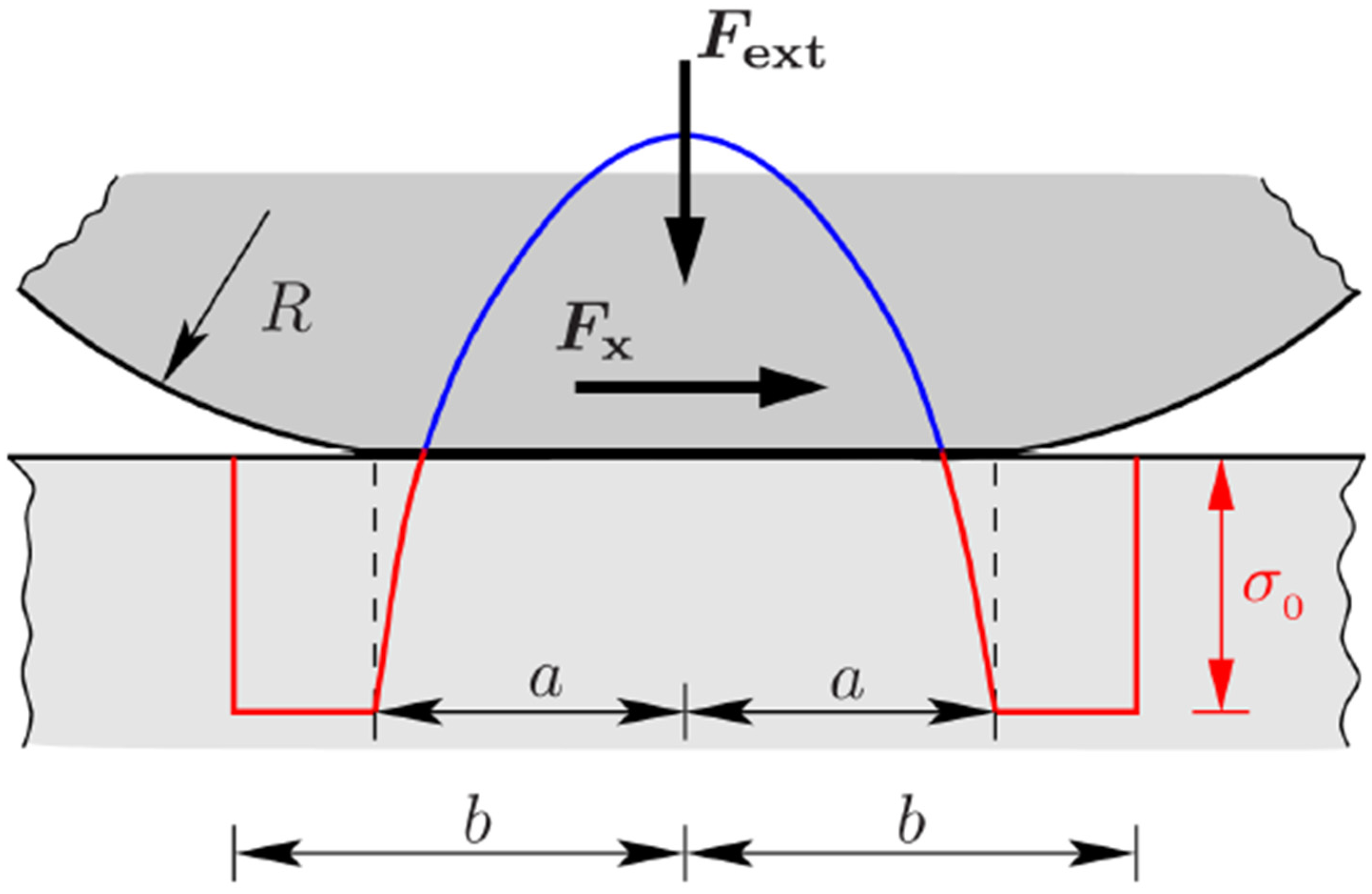
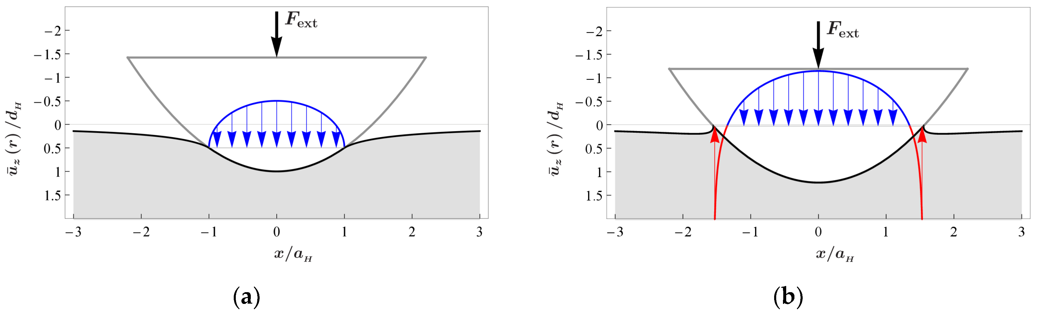
2.1. Contact Mechanics Approach

In 1992, Maugis developed an adhesion theory for the normal contact of elastic spheres based on a simple Dugdale approximation for the adhesive potential [14]. According to his theory, intimate contact is maintained over a central region of radius a and constant adhesive forces per unit area σ 0 are assumed to act in an annular region outside of the contact area whenever the gap between the two surfaces is less than a limiting value (see Figure 2).
Maugis’ theory became famous due to its ability to map the transition from Johnson-Kendall-Roberts (JKR) to Derjaguin-Muller-Toporov (DMT) and is probably one of the most widely used theory of adhesion. However, its applicability is restricted to adhesive normal contacts. A general theory of adhesion for tangential contacts does not exist, hence, it is still a subject of current research. In the present work, we take the results of a model proposed by Popov and Dimaki, which is based on a Coulomb–Dugdale approximation [12]. By using the method of dimensionality reduction [15], they studied the adhesive tangential contact, considering the general case of a contact with a stick and slip area. Here, we focus only on the limiting case of full slip, where the tangential force is simply defined by Coulombs law, which results in:
F R = μ F K = μ ( F ext + σ 0 π b 2 )
where F K denotes the normal contact force, F ext the externally applied force and b the radius to which the adhesive forces extend (see Figure 2). Although Popov and Dimaki did not explicitly report Equation (1), it follows directly from Equation (25) and (38) of their work [12]. Note, that the two-term form of Coulomb’s law given on the right side was already proposed by Derjaguin in 1934 [16]. Equation (1) states, that the normal contact force is composed of the externally applied force and an adhesive portion, which is simply given by the adhesive force per unit area times the area of the adhesive zone. By an asymptotic analysis, assuming that the adhesive process zone b-a becomes small in comparison to the contact radius, the results of the JKR theory were exactly reproduced and Equation (1) simplified to (see [17]).
F R = μ ( F ext + σ 0 π a 2 )
For further investigations, we will rely on this asymptotic approximation because it is sufficient to explain the qualitative approach for solving electroadhesive frictional contacts. The adhesive contribution in Equation (2) depends on the adhesive force per unit area as well as the contact area, which is given by:
A π R 2 = ( 9 π 8 Δ γ E * R + 9 π 8 Δ γ E * R + 3 4 F ext E * R 2 ) 4 / 3
where R is the radius of the assumed parabolic profile and E * the effective elastic modulus, defined by:
1 E * = 1 ν 1 2 E 1 + 1 ν 2 2 E 2
Herein, E 1 and E 2 denote the Young’s moduli of the contacting bodies, ν 1 and ν 2 are their Poisson’s ratios. According to Equation (3), the contact area itself is strongly influenced by the relative surface energy Δ γ and the externally applied force. The enlargement of the contact area due to the adhesive interactions is illustrated in Figure 3, which compares (a) the Hertzian normal contact and (b) the adhesive contact under the same applied external force, according to the JKR theory. Note, that in both figures the elastic normal stresses as well as the normal surface displacements are plotted qualitatively and quantitatively correct. Quantities are normalized to the indentation depth d H , contact radius a H and pressure maximum of the Hertzian contact. We have chosen an externally applied force of F ext   =   3 π R Δ γ , as an example, which results in an increase in the contact radius of about 50%.
At this point, we emphasize that the present model does not take into account a reduction in the contact area caused by the applied tangential force, as observed in experiments [18]. We assume that normal and tangential contact are uncoupled, which means that the normal force has no effect on the tangential stress distribution and the tangential force does not influence the pressure distribution. Strictly speaking, this is only valid for elastically similar contacting materials; for example, if one body is rigid and the other is incompressible. This is approximately fulfilled in the later-discussed application example of electrovibration. Of course, no real material is rigid, however, the elastic modulus of the touchscreen is much higher than that of the human skin. In addition, the human skin material has a Poisson ratio that differs only slightly from 0.5. Thus, we expect that coupling effects can be neglected. As one consequence, the contact area in the state of full slip is the same as in the normal contact with adhesion. However, extensions of the model reflecting a reduction of the contact area are conceivable.
By substituting Equation (3) in Equation (2), we obtain the friction force as a function of the external applied force as well, as the adhesion force per unit area and the relative surface energy.
F R ( F ext , Δ γ , σ 0 ) = μ [ F ext + σ 0 π R 2 ( 9 π 8 Δ γ E * R + 9 π 8 Δ γ E * R + 3 4 F ext E * R 2 ) 4 / 3 ]
The coupling of the contact mechanical model to electrostatics is achieved by recalculating the adhesion force per unit area and the relative surface energy, which forms the focus of the next section.

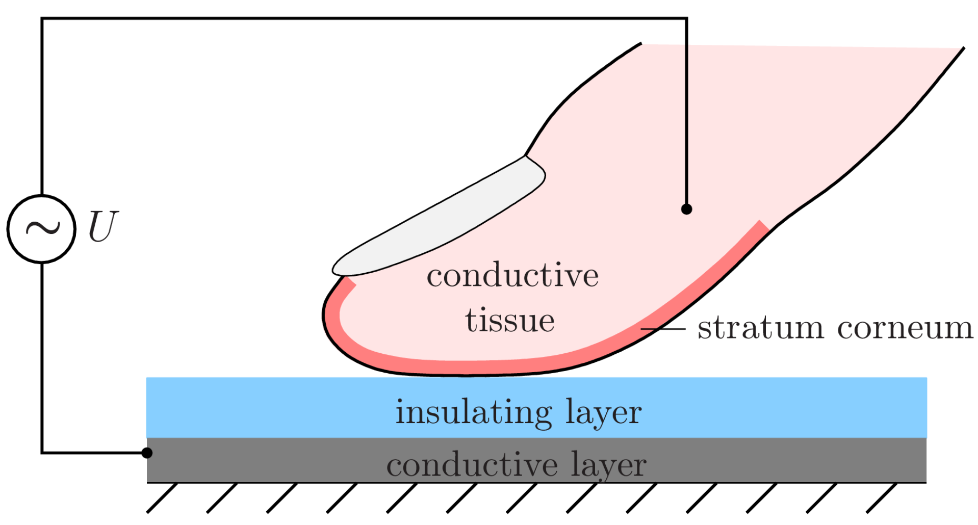
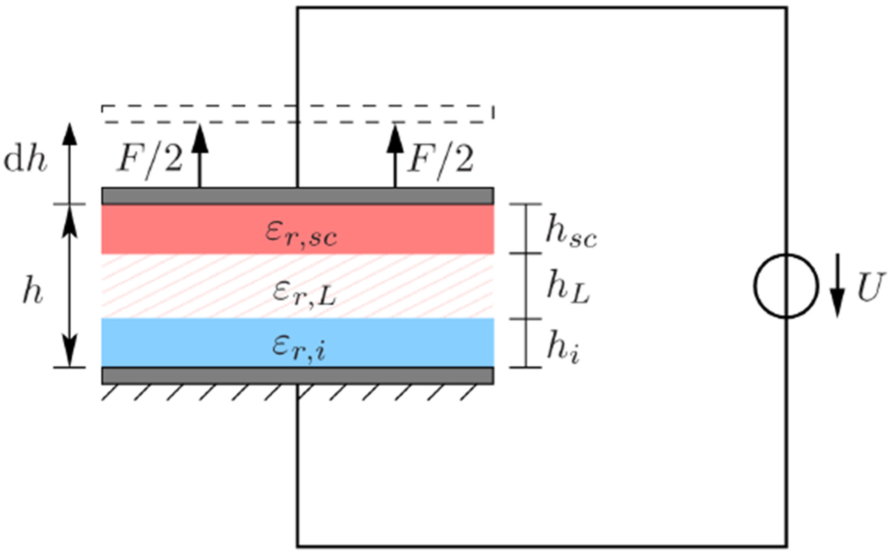
2.2. Electrostatic Approach and Coupling to Contact Mechanics

From an electrostatic point of view, the simple parallel-plate capacitor model is most commonly used to map the contact between the fingertip and touchscreen. Even Strong and Troxel, in their pioneering work in 1970, drew on this model [19]; we want to use it too. However, unlike the majority of models found in the literature, our model has a reliable connection to contact mechanics. We recalculate the adhesion force per unit area, as well as the relative surface energy from the parallel-plate capacitor model, which are then substituted in the friction force given by Equation (5). The model consists of two parallel plates coated with dielectric materials and separated from each other by an air gap (see Figure 4).
The total capacitance can be calculated by a simple series connection which leads to:
C = ε 0 A ( h s c ε r , s c + h L ε r , L + h i ε r , i ) 1
where ε 0 is the permittivity of free space, h s c , h L and h i the thicknesses of the stratum corneum, air gap and insulating layer of the screen, and ε r , s c , ε r , L and ε r , i are the corresponding relative permittivities. Note that the stratum corneum is assumed to be a perfect non-conducting layer. By application of the principle of virtual work, the attraction force F between the plates can be easily determined:
F = 1 2 U 2 d C d h = ε 0 A U 2 2 ε r , L ( h s c ε r , s c + h L ε r , L + h i ε r , i ) 2
and after division by the contact area the adhesion force per unit area is obtained:
σ ( h L , U ) = F A = ε 0 U 2 2 ε r , L ( h s c ε r , s c + h L ε r , L + h i ε r , i ) 2
The relative surface energy can be calculated according to its definition, as the required work per unit area for separating the plates:
Δ γ ( U , h L ) : = h L σ ( h ˜ L , U ) d h ˜ L = ε 0 U 2 2 ( h s c ε r , s c + h L ε r , L + h i ε r , i ) 1
Both quantities, the adhesion force per unit area as well as the relative surface energy are proportional to the amplitude of the applied AC voltage. A macroscopic approach is not able to take into account the roughness of the fingertip, especially the finger ridges, including their changes under applied pressure, in a direct way. This is the reason why we have included a small air gap, which we would like to call an equivalent air gap. The equivalent air gap can be prematurely interpreted only as a fitting parameter to ensure the closest possible match with experimental results. However, recent research deals with determining the air gap thickness. For example, Guo et al. showed that the air gap thickness is a power function of the applied external force under fixed (apparent) contact area [20]. For calculations, they have assumed that the sum of the non-contact air gap sections approximates the apparent contact area. It remains to be determined whether it would be better to use the apparent contact area minus the fingerprint ridge area instead. The latter is only 30% of the apparent contact area [21]. Here, we make use of a rough assumption of the equivalent air gap thickness and take a constant value of 5 μm, mentioned as an upper limiting value by Shultz et al. [5]. In the next section, we will show that, despite this rough assumption, the results obtained with the present model agree well with selected experimental data.

3. Comparison with Experimental Data

Before we proceed to compare the results obtained by the proposed macroscopic model with experimentally available data, in Table 1 we list the geometrical and material parameters used in our simulations. Almost all values are taken from the work of Meyer et al. [4]. The value for the thickness of the equivalent air gap was chosen as discussed in the previous section.
It should be noted that the chosen value for the equivalent effective elastic modulus is associated with some uncertainty. It is obvious that we can neglect the influence of the very stiff insulating layer compared with the soft skin for calculating the effective elastic modulus according to Equation (4), i.e.:
E * E skin 1 ν skin 2
However, human skin is a highly complex material, characterized by anisotropic, graded, nonlinear viscoelastic properties, thus it is difficult to map the skin by a single equivalent elastic parameter. Van Kuilenburg et al. introduced such an effective elastic modulus as a function of the contact radius and analyzed its length scale dependence [22]. From a macroscopic point of view, the effective elastic modulus is primarily determined by the softer, lower layers of the skin (epidermis, dermis, hypodermis) than the much stiffer stratum corneum. Further increase of the contact radius is associated with a growth in the effective elastic modulus, due to the influence of the stiff bone of the distal phalanx. Here, we presume a constant value for the equivalent elastic modulus of 40 kPa, which lies roughly in the range of values given in [22,23].

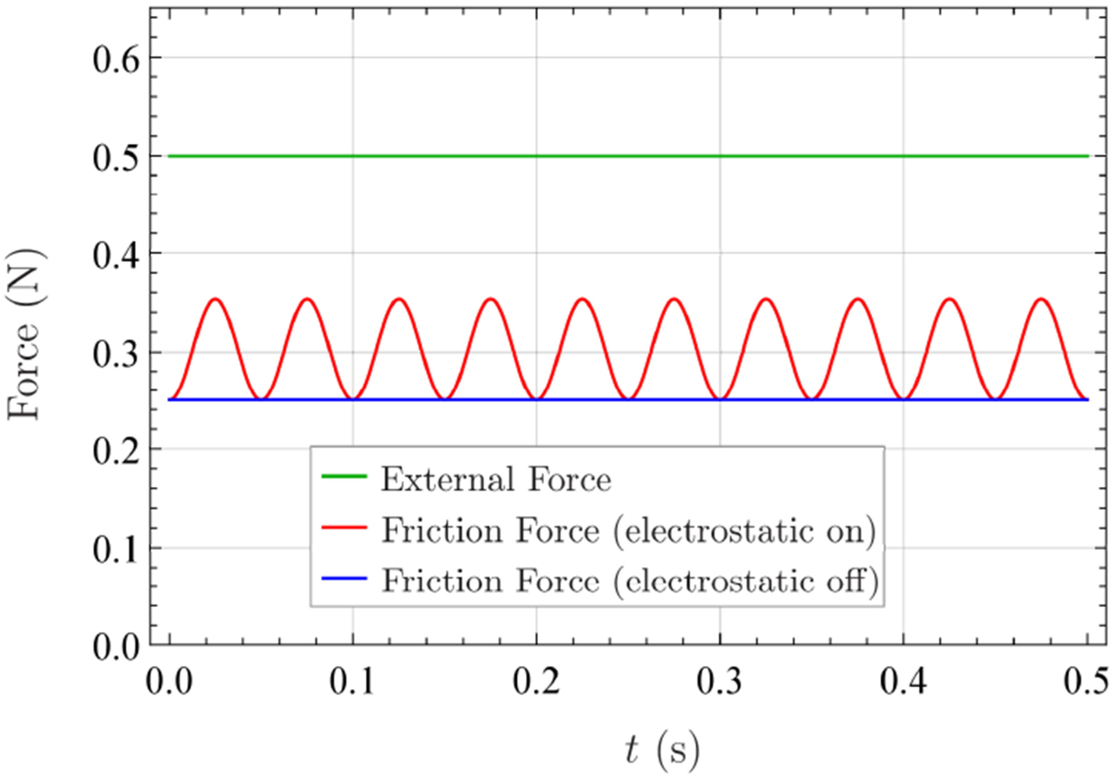
3.1. Friction Force as a Function of Time during Sinusoidal Excitation

In preparation for later, more important investigations, we want to validate our model in the present section. For this purpose, we apply a low-frequency sinusoidal AC voltage of 10 Hz and 140 V that was used by Meyer et al. [4] to test a specifically designed tribometer for measuring the friction force between the fingertip and screen. Taking this sinusoidal voltage signal in Equations (8) and (9) into account, and inserting both into Equation (5), lead to the friction force as a function of time. Figure 5 compares the external applied force with the friction force under the conditions that the voltage is turned on and off. A friction coefficient of 0.5 was assumed and the geometrical and material parameters listed in Table 1 were considered.
It is clear that the friction force under ON condition is greater than under OFF condition. In addition, it is observed that the frequency of friction force takes a value of 20 Hz, so twice the frequency of the applied AC voltage. This effect is self-evident, too. Whenever the applied voltage reaches an extremum, regardless of whether a maximum or minimum, the friction force takes a maximal value. The results obtained with the new model and depicted in Figure 5 are in good agreement with the experimental data given by Meyer et al. [4] (p. 45).

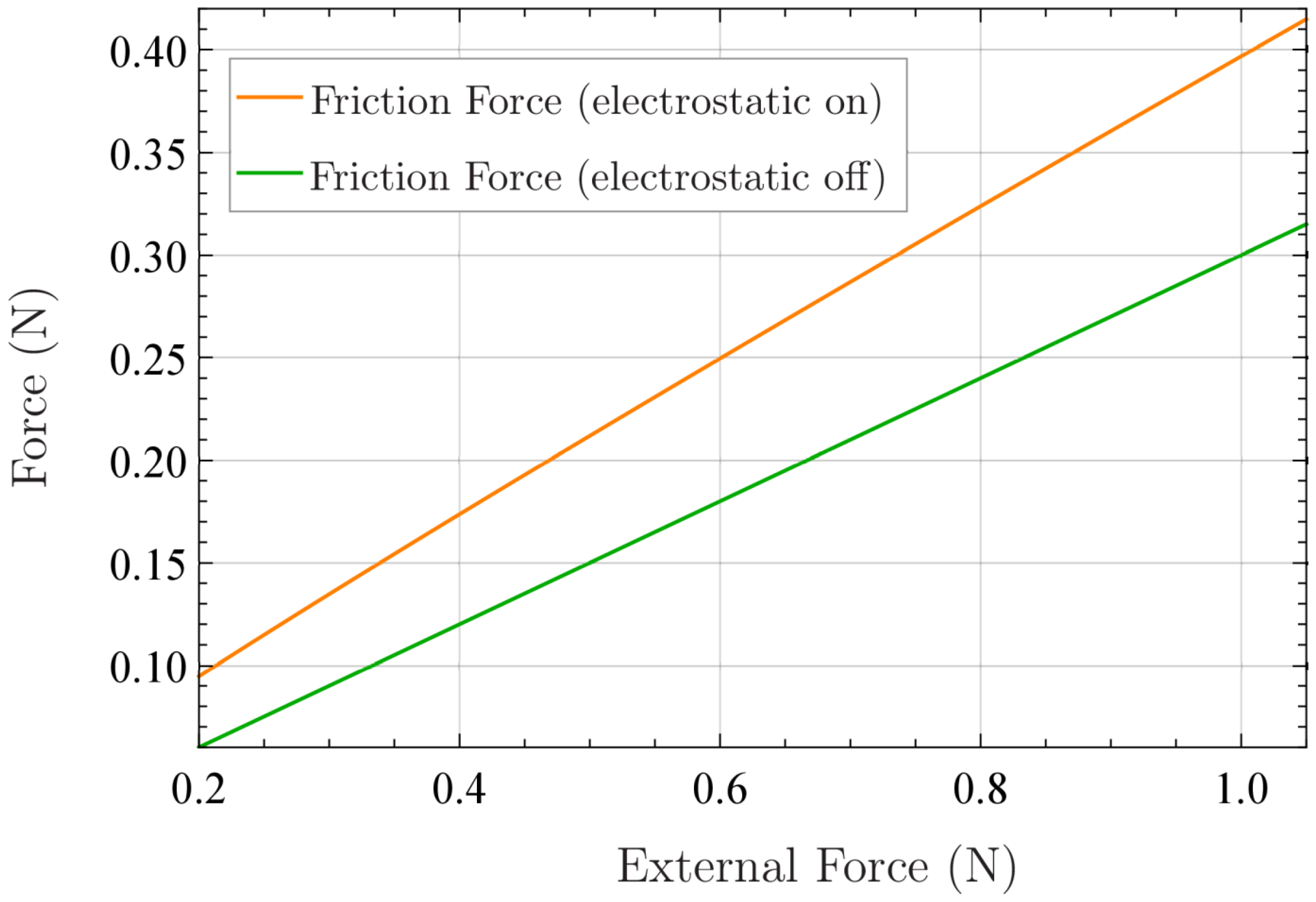
3.2. Friction Force as a Function of Externally Applied Normal Force

By applying a high-frequency square wave instead of a sine wave, the friction force no longer oscillates but becomes steady. In order to analyze the effect of the externally applied force as well as the voltage amplitude on the friction force, Meyer et al. have used high-frequency square wave input signals of 10 kHz and 140 V. They compared the measured (and averaged) friction forces with and without electrovibration. In this way, they were able to calculate the electrostatic contribution to the normal contact force, which is called inferred electrostatic force. Vodlak et al. [10] has supplemented the experimental data of Meyer et al. by fitted curves, which result from analytical expressions based on two competitive approaches for the attraction force between the plates of the parallel-plate capacitor model. The corresponding curves for the friction force as a function of the externally applied force under OFF and ON condition obtained with our model are illustrated in Figure 6. They are almost indistinguishable from the fitted curves of Vodlak et al. (see Figure 6a in [10]), and thus agree well with the experimental data.
At this point, we comment that our model is based on the calculation formula for the attraction force between the plates, which is much worse suited for electrovibration, according to Vodlak et al. They have shown that it can lead to wrong results, by orders of magnitude regarding the inferred electrostatic force as a function of the voltage amplitude. The same holds for the contact area as a function of the externally applied force. However, we strongly emphasize that these problems do not occur when using our model, which solely considers the geometrical and material parameters listed in Table 1. This is partly due to the introduced small air gap, which is always present, even in direct macroscopic contact between the fingertip and screen (in-contact state). In addition, our model is based on an improved coupling between contact mechanics and electrostatics. Of course, we cannot correctly represent the dependence of the externally applied force on the contact area over the entire range of typical loads of electrovibration. However, the discrepancies are mainly due to the assumption that the fingertip was mapped by a parabolically shaped homogeneous elastic half-space.

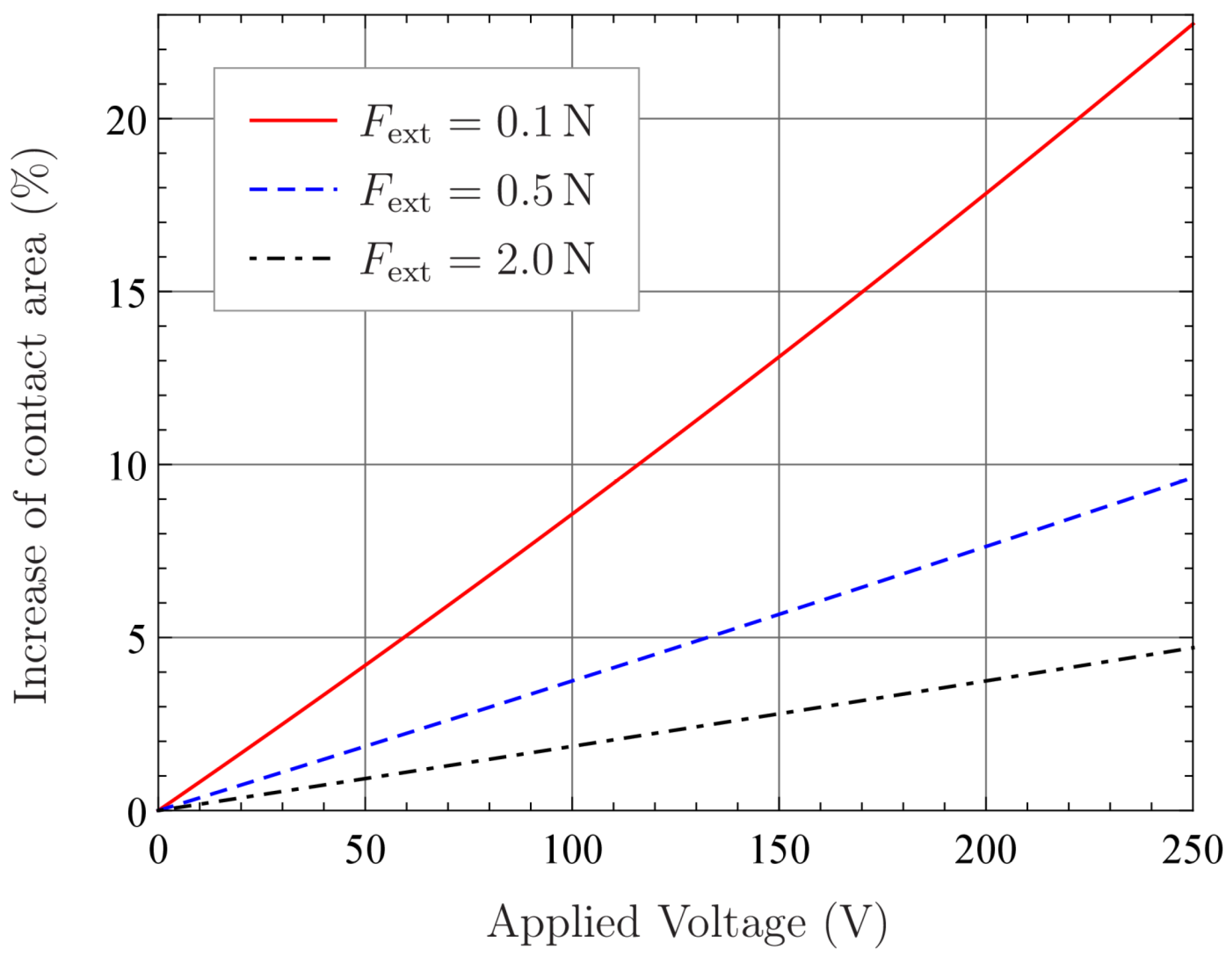
3.3. Electrostatic Force as a Function of Applied Voltage Amplitude

This section addresses the dependence of the (inferred) electrostatic force on the voltage amplitude. Meyer et al. have analyzed experimental data of seven subjects. Again, a high-frequency square wave of 10 kHz was applied and five input voltage amplitudes ranging from 60 V to 140 V considered. Although the measured electrostatic force varied significantly across subjects, all data indicated a square law behavior and thus supported expressions for the electrostatic force resulting from the parallel-plate capacitor model.
In order to show what the new model predicts, we take a closer look to its underlying equations. As previously mentioned, the (inferred) electrostatic force F el is nothing other than the electrostatic contribution to the normal contact force, which can be deduced directly from Equation (5).
F el = σ 0 A = σ 0 π R 2 ( 9 π 8 Δ γ E * R + 9 π 8 Δ γ E * R + 3 4 F ext E * R 2 ) 4 / 3
Note, that both the adhesion force per unit area σ 0 , as well as the relative surface energy Δ γ , are proportional to the square of the applied voltage. The apparent contact area itself depends on Δ γ and the externally applied normal force. Let us consider two limiting cases. First, we assume that the influence of the relative surface energy on the contact area is much larger than that of the external normal force. In this case, Equation (11) yields:
3 π 2 R Δ γ F ext 1 F el U 10 / 3 U 2
according to which, the electrostatic force as a function of the voltage follows a power-law with an exponent significantly higher than 2 and thus contradicts the experimental data. This relationship has already been noted in [13]. However, if the influence of the external normal force is much larger than that of the relative surface energy, the square law behavior is verified.
3 π 2 R Δ γ F ext 1 F el U 2
Indeed, by using the material and geometrical parameters listed in Table 1, the assumption according to Equation (13) holds, and thus the new model provides the desired result. But what does this assumption imply? It implies that we can neglect the influence of the voltage on the (apparent) contact area. Hence, the contact area can be simply determined by Hertz’s theory, instead of using the JKR theory. For this reason, we investigate the influence of the voltage amplitude and the external normal force on the contact area in more detail. Figure 7 illustrates the percentage change in the contact area over the applied voltage amplitude for three different externally applied normal forces lying in the typical range of electrovibration. For instance, if we apply an external normal force of 2 N and a voltage of 150 V, then the change of the contact area is only around 3%, and thus indeed neglectable.
However, the new model indicates that, in the case of external normal forces, less than 100 mN the influence of the voltage amplitude on the contact area becomes more and more important. At 150 V, the model presumes a 13% increase of the apparent contact area. Even if the influence of the voltage on the contact area can be neglected in a broad range of typical loads, forces smaller than 100 mN might be still relevant for electrovibration. Unlike almost all models, the presented new one seems to provide reliable results in this regime. Note, that the applicability of the new model is not restricted to electrovibration between the fingertip and touchscreen. It may also be of interest for robotics applications, where much higher voltages are present.

4. Summary and Discussion

We have introduced a new macroscopic model for voltage-induced frictional contacts. In contrast to most existing models, it offers a suitable coupling between contact mechanics and electrostatics. For this purpose, we have exploited classical adhesion theories and recalculate the adhesion force per unit area, as well as the relative surface energy from electrostatics. Under the assumption of Coulomb friction in the contact interface, a closed form equation for the friction force has been derived.
As an exemplary application, we have considered the frictional contact between the fingertip and touchscreen under electrovibration. By comparison with available experimental data, the suitability of the new model has been proven. The obtained results for the friction force as a function of the externally applied force agree well with measured data. The same holds for the electrostatic force as a function of voltage amplitude. From an electrostatic point of view, the introduced equivalent air gap, for which we have taken a roughly estimated constant value, is of particular interest. On the one hand, the equivalent air gap can be interpreted as a pure fitting parameter to ensure the closest possible match with experimental results. On the other hand, recent research deals with determining its thickness. In any case, further investigations are necessary to clarify its effect.
Another finding that emerges from the results obtained with the new model concerns the influence of the voltage amplitude on the apparent contact area. Regarding electrovibration between the fingertip and touchscreen, for external normal forces lower than 100 mN the influence of the voltage amplitude can no longer be neglected. The same should apply for significantly higher forces in robotics applications, due to much larger allowable voltages.
Furthermore, we emphasize once again that the new model cannot reflect a reduction of the contact area caused by the applied tangential force. The contact area under gross slip is assumed to be the same as in normal contact with adhesion. However, extensions of the model are possible and should be a subject of further research. Finally, we point out that our model is based on the half-space approximation and linear elasticity. Although we make use of an equivalent effective elastic modulus, its applicability to electrovibration between the fingertip and touchscreen requires further investigation. Human skin is a highly complex material, characterized by anisotropic, graded, nonlinear viscoelastic properties, thus the JKR theory can only provide a rough estimation of the contact area as a function of the external normal force as well as the applied voltage.

Author Contributions

Conceptualization, M.H. and V.L.P.; methodology, M.H. and V.L.P.; validation, M.H. and V.L.P.; writing—original draft preparation, M.H.; supervision, V.L.P.

Funding

This research received no external funding.

Acknowledgments

We would like to acknowledge support from the German Research Foundation and the Open Access Publication Funds of Technische Universität Berlin.

Conflicts of Interest

The authors declare no conflict of interest.

References

  1. Mallinckrodt, E.; Hughes, A.L.; Sleater Jr, W. Perception by skin of electrically induced vibrations. Science 1953, 118, 277–278. [Google Scholar] [CrossRef] [PubMed]
  2. Shintake, J.; Cacucciolo, V.; Floreano, D.; Shea, H. Soft robotic grippers. Adv. Mater. 2018, 30, 1707035. [Google Scholar] [CrossRef] [PubMed]
  3. Bau, O.; Poupyrev, I.; Israr, A.; Harrison, C. TeslaTouch: Electrovibration for touch surfaces. In Proceedings of the 23nd annual ACM symposium on User interface software and technology, New York, NY, USA, 3–6 October 2010; pp. 283–292. [Google Scholar]
  4. Meyer, D.J.; Peshkin, M.A.; Colgate, J.E. Fingertip friction modulation due to electrostatic attraction. In Proceedings of the IEEE 2013 world haptics conference, Daejeon, Korea, 14–17 April 2013; pp. 43–48. [Google Scholar]
  5. Shultz, C.D.; Peshkin, M.A.; Colgate, J.E. Surface haptics via electroadhesion: Expanding electrovibration with Johnsen and Rahbek. In Proceedings of the IEEE 2015 world haptics conference, Evanston, IL, USA, 22–26 June 2015; pp. 57–62. [Google Scholar]
  6. Vardar, Y.; Güçlü, B.; Basdogan, C. Effect of waveform on tactile perception by electrovibration displayed on touch screens. IEEE Trans. Haptics 2017, 10, 488–499. [Google Scholar] [CrossRef] [PubMed]
  7. Nakamura, T.; Yamamoto, A. Modeling and control of electroadhesion force in DC voltage. Robomech J. 2017, 4, 18. [Google Scholar] [CrossRef]
  8. Kaczmarek, K.A.; Nammi, K.; Agarwal, A.K.; Tyler, M.E.; Haase, S.J.; Beebe, D.J. Polarity effect in electrovibration for tactile display. IEEE Trans. Biomed. Eng. 2006, 53, 2047–2054. [Google Scholar] [CrossRef] [PubMed]
  9. Vezzoli, E.; Amberg, M.; Giraud, F.; Lemaire-Semail, B. Electrovibration modeling analysis. In Proceedings of the International Conference on Human Haptic Sensing and Touch Enabled Computer Applications, Versailles, France, 24–26 June 2014; pp. 369–376. [Google Scholar]
  10. Vodlak, T.; Vidrih, Z.; Vezzoli, E.; Lemaire-Semail, B.; Peric, D. Multi-physics modelling and experimental validation of electrovibration based haptic devices. Biotribology 2016, 8, 12–25. [Google Scholar] [CrossRef]
  11. Lyashenko, I.A. Tangential displacement influence on the critical normal force of adhesive contact breakage in biological systems. Facta Univ. Series: Mech. Eng. 2016, 14, 313–320. [Google Scholar] [CrossRef]
  12. Popov, V.L.; Dimaki, A.V. Friction in an adhesive tangential contact in the Coulomb-Dugdale approximation. J. Adhes. 2017, 93, 1131–1145. [Google Scholar] [CrossRef]
  13. Popov, V.L.; Hess, M. Voltage induced friction in a contact of a finger and a touchscreen with a thin dielectric coating. arXiv 2018, arXiv:1805.08714, in press. [Google Scholar]
  14. Maugis, D. Adhesion of spheres: The JKR-DMT transition using a Dugdale model. J. Colloid Interface Sci. 1992, 150, 243–269. [Google Scholar] [CrossRef]
  15. Popov, V.L.; Heß, M. Method of Dimensionality Reduction in Contact Mechanics and Friction; Springer: Berlin/Heidelberg, Germany, 2015. [Google Scholar]
  16. Derjaguin, B. Molekulartheorie der äußeren Reibung. Z. Phys. 1934, 88, 661–675. [Google Scholar] [CrossRef]
  17. Popov, V.L.; Heß, M.; Willert, E. Adhesive Tangential Contact. In Handbook of contact mechanics; Springer: Berlin/Heidelberg, Germany, 2019. [Google Scholar]
  18. Savkoor, A.R.; Briggs, G.A.D. The effect of tangential force on the contact of elastic solids in adhesion. Proc. R. Soc. London A. Math. Phys. Sci. 1977, 356, 103–114. [Google Scholar] [CrossRef]
  19. Strong, R.M.; Troxel, D.E. An electrotactile display. IEEE Trans. Man-Mach. Syst. 1970, 11, 72–79. [Google Scholar] [CrossRef]
  20. Guo, X.; Zhang, Y.; Wang, D.; Lu, L.; Jiao, J.; Xu, W. The Effect of Applied Normal Force on the Electrovibration. IEEE Trans. Haptics 2019, in press. [Google Scholar] [CrossRef] [PubMed]
  21. Soneda, T.; Nakano, K. Investigation of vibrotactile sensation of human fingerpads by observation of contact zones. Tribol. Int. 2010, 43, 210–217. [Google Scholar] [CrossRef]
  22. Van Kuilenburg, J.; Masen, M.A.; van der Heide, E. Contact modelling of human skin: What value to use for the modulus of elasticity? Proc. Inst. Mech. Eng. Part J: J. Eng. Tribol. 2013, 227, 349–361. [Google Scholar] [CrossRef]
  23. Dzidek, B.M.; Adams, M.J.; Andrews, J.W.; Zhang, Z.; Johnson, S.A. Contact mechanics of the human finger pad under compressive loads. J. R. Soc. Interface 2017, 14, 20160935. [Google Scholar] [CrossRef] [PubMed]
Figure 1. Schematic representation of the electromechanical frictional contact between the index fingertip and touchscreen.
Lubricants 07 00102 g001
Figure 2. Qualitative representation of the adhesive tangential contact between an elastic sphere and a rigid plane; the distribution of the elastic normal stresses at the surface according to Maugis’ theory is included.
Lubricants 07 00102 g002
Figure 3. Normalized representation of the elastic normal stresses and normal surface displacements in a contact between a rigid parabolic indenter and an elastic half-space: (a) Non-adhesive contact according to Hertz; (b) Adhesive contact according to Johnson, Kendall and Roberts.
Lubricants 07 00102 g003
Figure 4. Parallel-plate capacitor for modeling the contact between the fingertip and touchscreen from an electrostatic point of view.
Lubricants 07 00102 g004
Figure 5. External applied force (green) and friction force under both conditions: electrovibration is turned on (red) and turned off (blue).
Lubricants 07 00102 g005
Figure 6. Friction force as a function of externally applied force under both conditions: electrostatic forces due to an applied high-frequency square wave voltage are turned off (green) and on (orange).
Lubricants 07 00102 g006
Figure 7. Percentage increase of the apparent contact area as a function of the applied voltage amplitude for three different externally applied normal forces: 0.1 N, 0.5 N and 2.0 N.
Lubricants 07 00102 g007
Table 1. List of material and geometrical parameters used in simulations with the proposed model.
SymbolParameter NameValue and Unit
μ Friction coefficient 0.5 (0.3)
R Radius of fingertip1 cm
E * Equivalent effective elastic modulus40 kPa
ε r , s c Relative permittivity of stratum corneum 1650
ε r , i Relative permittivity of insulating layer 3.35
ε 0 Permittivity of free space 8.854 · 10 12 A s V m
h s c Thickness of stratum corneum300 µm
h i Thickness of insulating layer1 µm
h L Thickness of equivalent air gap5 µm
F ext External applied normal force0.5 N

