Article

Performance of Volcano-Like Laser Textured Cutting Tools: An Experimental and Simulative Investigation

1
School of Mechanical and Power Engineering, Nanjing Tech University, Nanjing 211800, Jiangsu, China
2
School of Mechanical Engineering, Jiangsu University, Zhenjiang 212013, Jiangsu, China
3
School of Mechanical Engineering, Purdue University, West Lafayette, IN 47906, USA
*
Author to whom correspondence should be addressed.
Lubricants 2018, 6(4), 98; https://doi.org/10.3390/lubricants6040098
Submission received: 9 July 2018 / Revised: 30 July 2018 / Accepted: 1 August 2018 / Published: 7 November 2018
(This article belongs to the Special Issue Tribological Performance of Textured Surfaces)

Abstract

:
In recent years, surface texturing in micro-scale has been attempted on the surface of cutting tools for multiple purposes, e.g., cutting force reduction, prolonging life-span, anti-adhesion, etc. With respect to machinability and performance, micro-groove texture (MGT) has dominated in this field compared to other textured patterns. In this study, a novel volcano-like texture (VLT) was fabricated on the rake face of cemented carbide inserts (WC-Co, YG6) by fiber laser. The following cutting experiment tested the flat, MGT and VLT tools in turning aluminum alloy 6061. The effects of coolant and cutting conditions were investigated. In addition, a validated FEM model was employed to explore the distribution of stress and temperature fields in the tool-chip interface. The initial forming process of adhesion layer on rake face was investigated as well. The results indicated that lower cutting force and less adhesion can be achieved by small scale VLT. This study not only introduced VLT on cutting tools but also revealed its comprehensive performance.

Graphical Abstract

1. Introduction

Formerly, the shape design of the majority of cutting tools has focused on macro features, such as rake angle, flank angle, edge inclination and chip-breakers. These features are elaborately designed for promoting cutting performance and tools’ life-span. Recent advances in coating and manufacturing technologies have opened up new horizons for cutting tool research and design, i.e., using micro/nano scales. In this field, a long trial list [1,2] can be found in surface texturing technology, which processes controllable and functional micro-scale structures on moving part surfaces [3,4], contributing to friction reduction, abrasive resistance, etc.
The first paper on surface textured tools was published in 2007 [5]. However, since this paper was not written by English, this new concept was not well-known until 2009 when two academic papers were published and indexed by the Web of Science [6,7]. They expounded the possibility and effectiveness of applying micro/nano surface textures on tool surfaces. Overall, it has been revealed that proper surface textured tools have advantages in reducing cutting force [6,8], suppressing contact length [9], anti-adhesion [10], and better machining quality [11] and wear resistance [12]. For instance, Xie et al. [13] found a 32.7% reduction in cutting forces in machining titanium alloy for micro-groove textured (MGT) tools. Sugihara et al. [14] also claimed that banded grooves decreased the friction coefficient on the rake face when it is applied on carbon-steel machining tools. Several models have been proposed, for instance, Kim et al. [15] deemed that the air gaps in the tool-chip interface may induce hydrophobicity and result in reduced adherence; and Kang et al. [16] simulated the hydrodynamic lubrication at the tool and chip interface and found that only micro-grooves in a specific orientation could generate extra film pressure to decrease friction.
Many surface textures were inspired by the research of bionics [17], e.g., the super-hydrophobic properties of a lotus leaf [18], the water-trapping ability of desert beetles’ backs [19] and drag reduction of the riblets on shark skin [20]. These bionic features can be manufactured by using three approaches: (1) partially removing the surface material; (2) overlaying foreign material; and (3) self-assembling by external stimulus. The first approach can be easily accomplished by laser ablation [21], electrical discharge machining (EDM) [22] and mechanical grinding [23]; the latter two can be achieved by laser re-melting, which generates uneven features with a volcano-like shape. This has been widely used on rolls to accurately control the surface profile and roughness, promoting the quality of steel sheet [24].
To the best of our knowledge, although the laser re-melting process has not been applied on tool surfaces [1], several theoretical studied can be found. By FEM molding, Ma et al. [25] forecasted that rake face textured tools could reduce the main force and thrust force by 10% and 20%, respectively, in dry cutting. In addition, Zhang et al. [26] revealed that a sphere-shaped texture had an obvious anti-adhesion effect with regard to van der Waals’ forces. Considering these theoretical studies, it seems worth investigating the practical application of a volcano-like texture (VLT) on the tools’ surface and assessing its cutting performance.
In this study, a new texture for cemented carbide tool surfaces was developed, followed by experiments using it in various cutting conditions. The effects of textured densities, cutting speed and coolant on cutting forces, rake face wear and chip shapes were analyzed systematically. The cutting process was simulated by a validated FEM model to show the stress and temperature field distribution of the tool-chip interface and the process of forming the adhesion layer. This research aims at providing detailed research of surface textured tools and to further enrich the design and manufacture approaches.

2. Experiment and Simulation Details

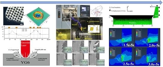
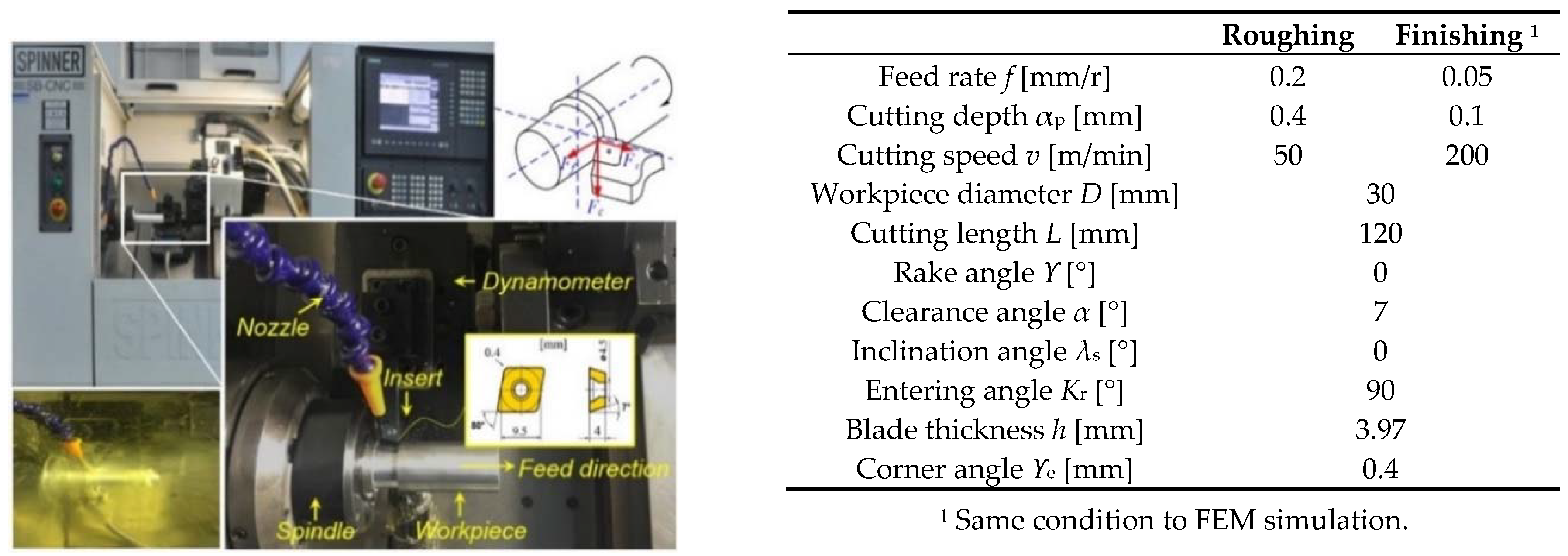
2.1. Texture Fabrication

Two kinds of texture patterns, volcano-like texture (VLT) and micro-groove texture (MGT), were fabricated on carbide tools by CW fiber laser (SPI Lasers Ltd., Southampton, UK, Redpower R4, wavelength 1070 nm, minimum pulse duration 10 μs) and Nd: YAG laser (CEO® REA series, Q-switched, St. Louis, MO, USA). MGT was achieved by laser ablation, while VLT was formed by a laser re-melting process. In order to improve the accuracy of measurement and fabrication, all tested tools were normalized to roughness Ra 0.2 μm by polishing. Figure 1 shows the textured rake faces, measured by white light interference microscope (Nano-focus Ltd., Glen Allen, VA, USA, µsurf explorer). As shown in Figure 1a,b, VLT is a composite morphology containing convex and concave regions; the outer diameter of the ring-shaped bump was regarded as its diameter, dv. The characterization adopted the parameter systems in [27]. The width and depth of MGT referenced the previous research in [28,29], as shown in Figure 1c,d. The detailed textured schemes are shown in Table 1.

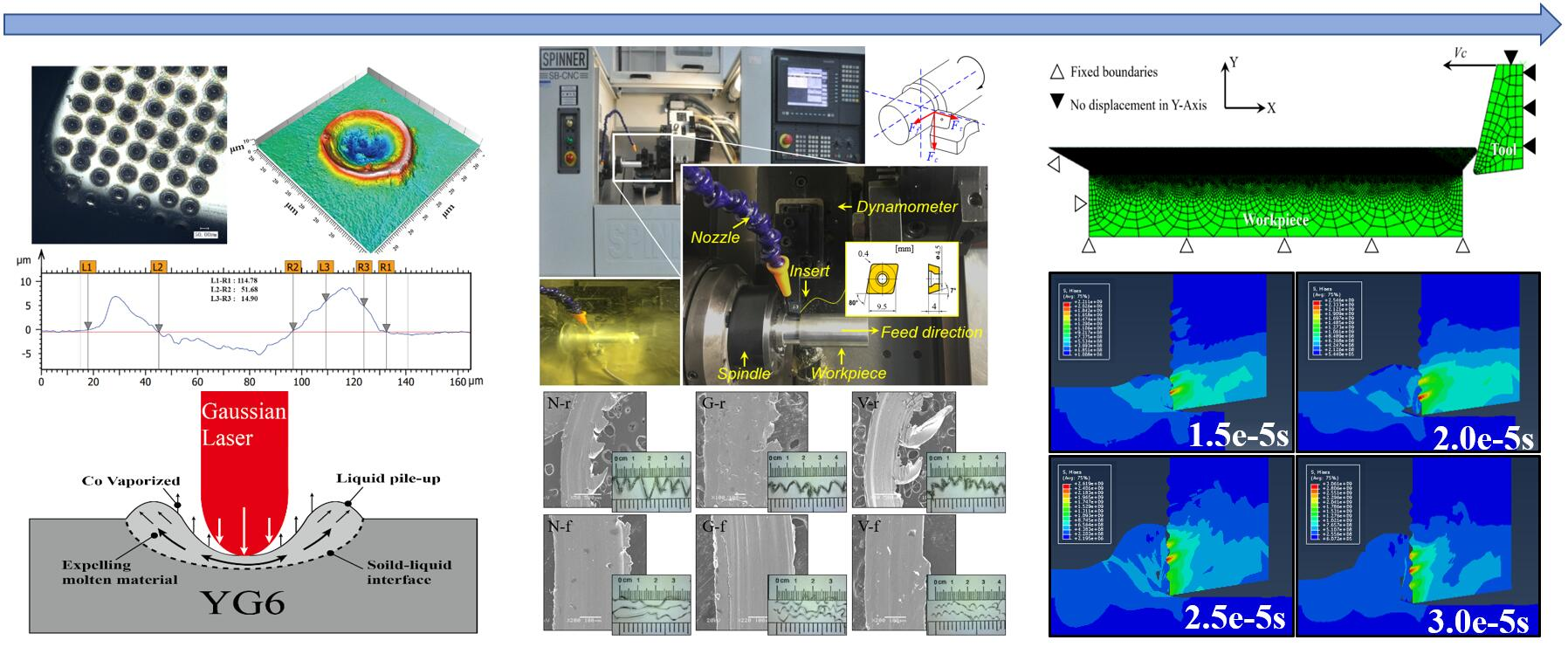
2.2. Cutting Experiment
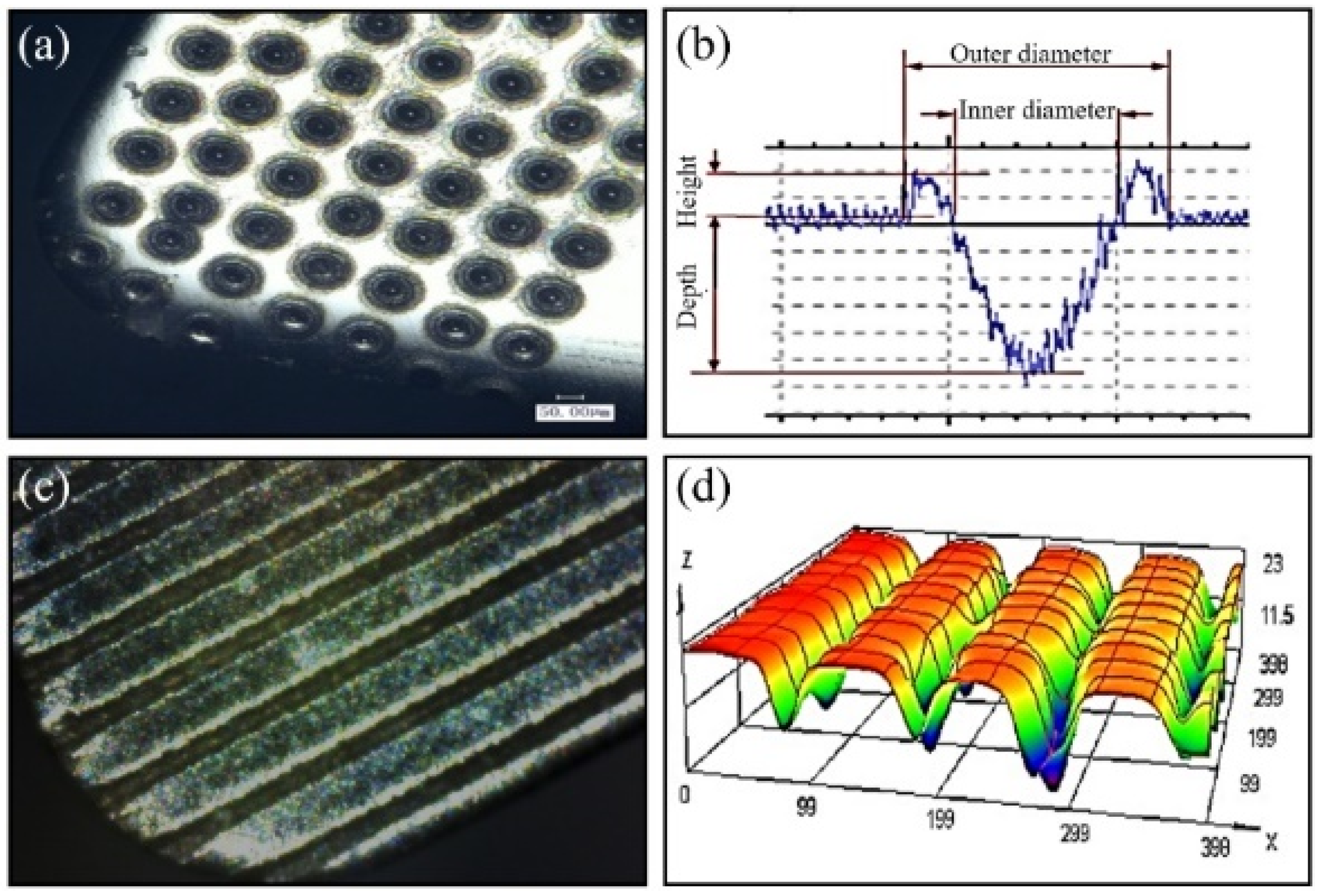
The cutting test were conducted on an ultra-precision lathe machine (Spinner SB/C/CNC, Sauerlach, Germany) as shown in Figure 2. The workpieces, aluminum alloy A6061 bar with 35 mm diameter and 180 mm length, were machined by feeding along its axial direction. A6061 is widely used in automobile, aircraft and light industries because of its high strength to mass ratio, corrosion resistance and excellent recycling potential. However, its low melting point and high ductility often cause severe tool-chip adhesion and poor machinability of precision processes. Two cutting conditions were included in the test, roughing and finishing. The feed rate and cutting depth were 0.05 mm/r and 0.1 mm in finishing; these parameters were quadrupled in roughing. The cutting speed of roughing is one-fourth of finishing. Besides the cutting condition, dry and wet cutting were also compared to show the coolant compatibility of different textured tools.

2.3. FEM Simulation

The simulative model in this study refers to Zhang’s model [30], which is a multi-part FEM model with four geometrical parts: (1) Part-1, the insert active part, (2) Part-2, the uncut chip thickness, (3) Part-3, the tool-tip passage zone, and (4) Part-4, the workpiece support. A satisfactory agreement was found between the numerical results and experimental data. As shown in Figure 3, the cutting tool was assumed to be fixed on its top and right sides, and the workpiece was allowed to move horizontally from the left to the right while restrained vertically.
The material constitutive model of Ti-6Al-4V follows the Johnson-Cook (J-C) model [31]. It provides a satisfactory description of the behavior of metals and alloys since it considers large strains, high strain rates, and temperature dependent viscoplasticity. This model is expressed by the following expression of the equivalent stress:
σ ¯ J C = [ A + B ( ε ¯ p ) n ] [ 1 + C ( ε ¯ ˙ p ε ¯ ˙ 0 ) ] [ 1 ( T T 0 T m T 0 ) m ]
where A, B, C, m and n are the material parameters, ε ¯ p is the Von Mises equivalent plastic strain, ε ¯ ˙ p is the Von Mises equivalent plastic strain rate, ε ¯ ˙ 0 is the reference equivalent plastic strain rate, and Tm and T0 are the material melting temperature and the reference ambient temperature. The values of the above parameters are shown in Table 2. Beside the parameters used in the J-C model, the basic mechanical and thermal properties of the A6061 and YG6 are presented in Table 3.

3. Results and Discussion

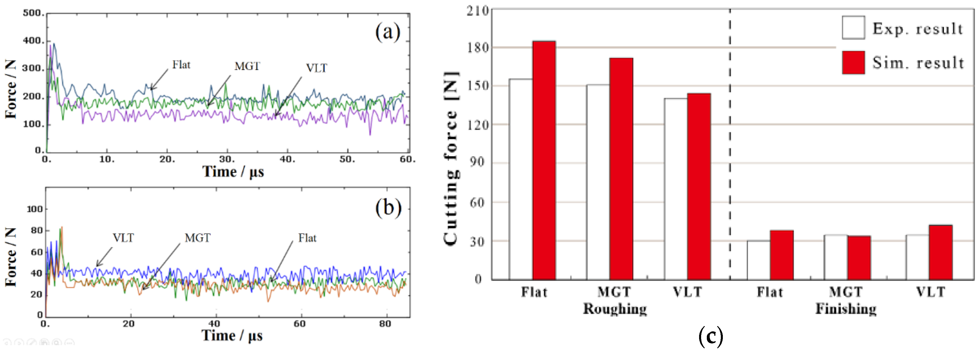
3.1. Numerical Model Validation

Figure 4a presents the main historical cutting forces in rough cutting. In the initial moment of tool and workpiece contact (0–10 µs), the instantaneous impact leads to a great fluctuation. After that, the cutting forces become stable throughout the whole analysis period. The VLT tool has an obvious lower cutting force comparing to flat and MGT tools; the reduction rate is nearly 29%. Figure 4b shows the simulated cutting forces in the finishing stages of cutting. In this case, MGT and flat tools show similar cutting forces in the stable stage. However, the VLT tool presents a higher-level curve.
To validate the FEM model, simulative and experimental main cutting forces were contrasted, as shown in Figure 4c. Although most simulated results exhibited higher values than the experiment, the results were still similar, not only in the same magnitude, but they also had the same tendency. Based on the comparisons, it can be said that the FEM model can be used to simulate the cutting process in good agreement with experimental results.

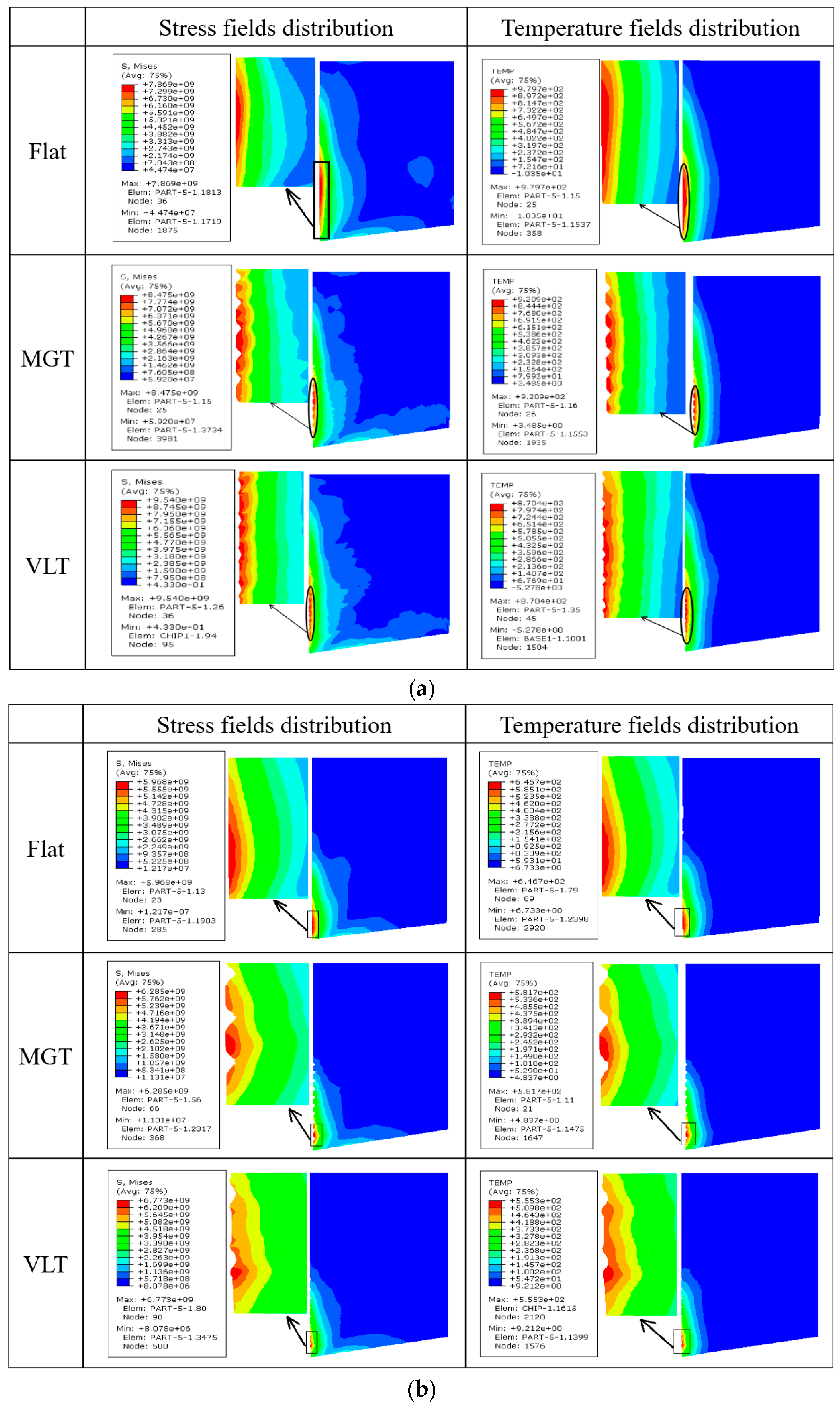
3.2. Stress and Temperature Field Distribution
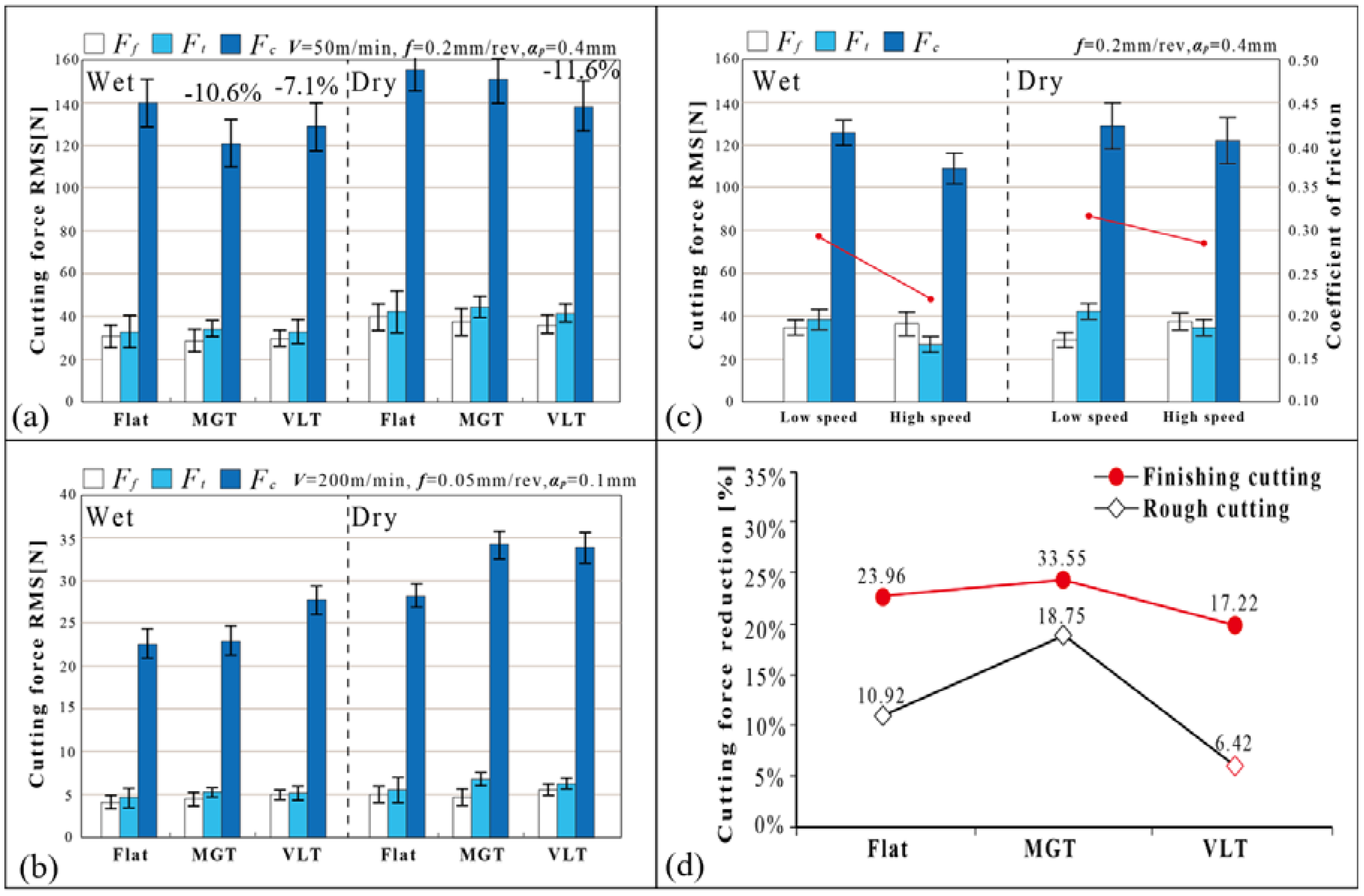
Figure 5 shows the distributions of stress and temperature fields on rake faces simulated by the FEM model. In essence, the rake face textured with MGT and VLT, resulted in discrete field distribution and values. Of all tested tools, the flat tool had the lowest max. stress and highest max. temperature in both roughing and finishing conditions. VLT tools, on the other hand, had the highest max. stress value in both rough and finish cutting, and high stress fields located around the texture morphology because of the reduced contact area. Another obvious feature was the distinct tool-chip contact length; the contact length of finishing is around one third of roughing, reducing the number of functional texture morphologies.
For MGT tools, the decreased proportions of maximum temperature (TEMP) were 6% and 14% in rough and finish cutting, respectively; and they were 11% and 14%, respectively, for VLT tools. Generally, the reduction in tool-chip contact area has a positive effect on friction heat restriction. This could be the main reason that VLT showed better heat restriction effect than MGT, since VLT is able to further increase the gap in the tool-chip interface. In finish cutting, higher stress and TEMP field distribution could be observed around the first VLT feature counted from the cutting edge, indicating that the frontier features were more important than posterior features. The design of VLT should consider the factor of uneven distribution of stress and temperature fields on the rake face; although, in this study, all VLT features have the same parameters in order to lessen the difficulty of manufacturing.
The process of forming an adhesion layer in the initial stage of roughing was simulated by the FEM model, as shown in Figure 6. The formation of the adhesion layer includes four steps: (1) in the period of 0–15 μs, the convex morphology interlocks the sliding chip and bends the chip due to high contact stress; (2) then, in the period of 15–20 μs, the main body of chip slides along the rake face, while the interlocking part cannot move freely, meanwhile, the inter stress of the chip increases; (3) in the period of 20–25 μs, as the sheer stress of the chip exceeds the damage threshold of the work material, a part of the chip is bonded onto the rake face and separated from the chip; and (4) finally, in the period of 20–25 μs, the bonded part is separated from the chip and forms an adhesion layer on the rake face, whose thickness exceeds the height of the bump of VLT. Kümmel et al. [32] believed that if the bonded layer was strong enough, it could protect the tool surface, increasing the tool’s life-span. The following study will further verify this possibility experimentally.
The above analysis implies a criterion for adhesive layer generation, the contact stress between chip and VLT feature reaches the damage threshold of the work material; in other words, VLT’s anti-adhesion ability is more likely to be exerted in small feed rate cutting, e.g., the finish cutting condition in this study. Another approach to avoid this scenario is to keep a certain distance between VLT features and the cutting edge, where bears the highest normal stress. This conclusion matches the results from another research group. Fatima et al. [8] found that the distance of structures from the cutting edge is a significant structural geometric parameter. Its contribution to feed forces is about 84%.

3.3. Cutting Forces

The cutting forces were measured by a three-component dynamometer (Kistler 9257B). The average friction coefficient at the tool-chip interface could be calculated based on the following equation [33]:
μ   =   tan β   =   tan   ( γ 0 +   arctan F t F c )  
where β is the friction angle, γ0 is the rake angle, Ft is radial thrust force and Fc is the main cutting force. The directions of cutting forces are presented in Figure 2.
Figure 7a shows the RMS cutting forces of the tested tools during rough cutting. It can be seen that the MGT tool was more effective in wet machining; its resultant force decreased 10.6%; in contrast, this force reduction was inconspicuous in dry cutting. On the other hand, VLT tool showed consistent resultant force reductions in both conditions; 7.1% in wet cutting and 11.6% in dry cutting. Figure 7b shows the RMS cutting forces of tested tools in finish cutting. Compared with roughing, the quartered cutting depth and four-fold cutting speed led to a greatly reduction in cutting forces. It can be seen that all the textured tools had higher cutting forces in finish cutting, which was quite different from the result of roughing; meanwhile, the cutting forces of the MGT tool was similar to a flat tool in wet cutting. The above phenomenon implied that MGT and VLT tools have different work mechanism and sensitivity to coolant.
Figure 7c shows the cutting forces of VLT tools at low and high cutting speeds. Lower friction coefficients and cutting forces can be seen in higher speed cutting, and this tendency is more obvious in wet cutting. The main mechanism might be attributed to two aspects; first, the penetrating of coolant is promoted since VLT increased the gap in the tool-chip interface; second, higher speed cutting could benefit the hydrodynamic lubrication effect produced by textured surfaces.
The above analysis indicated that the usage of coolant decreases cutting forces, although, which type of texture is more compatible to coolant still needs to be verified. Figure 7d shows the resultant decline in the proportion of the cutting forces in rough and finish cutting. Obviously, the reduction percentages for finishing were all higher than roughing, indicating that for all tools, the coolant was more effective in finishing. MGT tools had the maximum reduction, while VLT tools showed the minimum reduction in both cutting conditions. In other words, only MGT was able to improve the efficiency of the coolant. In rough cutting, the cutting force of the VLT tool only decreased 6.42% after using the coolant.

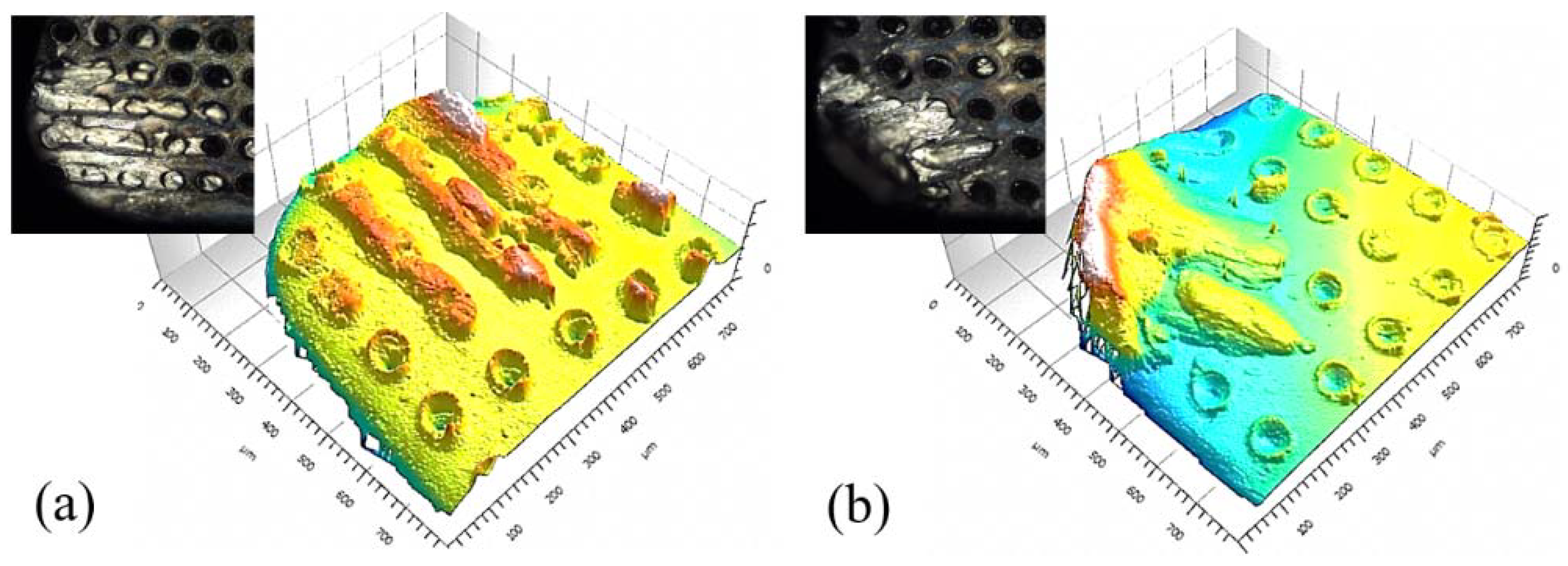
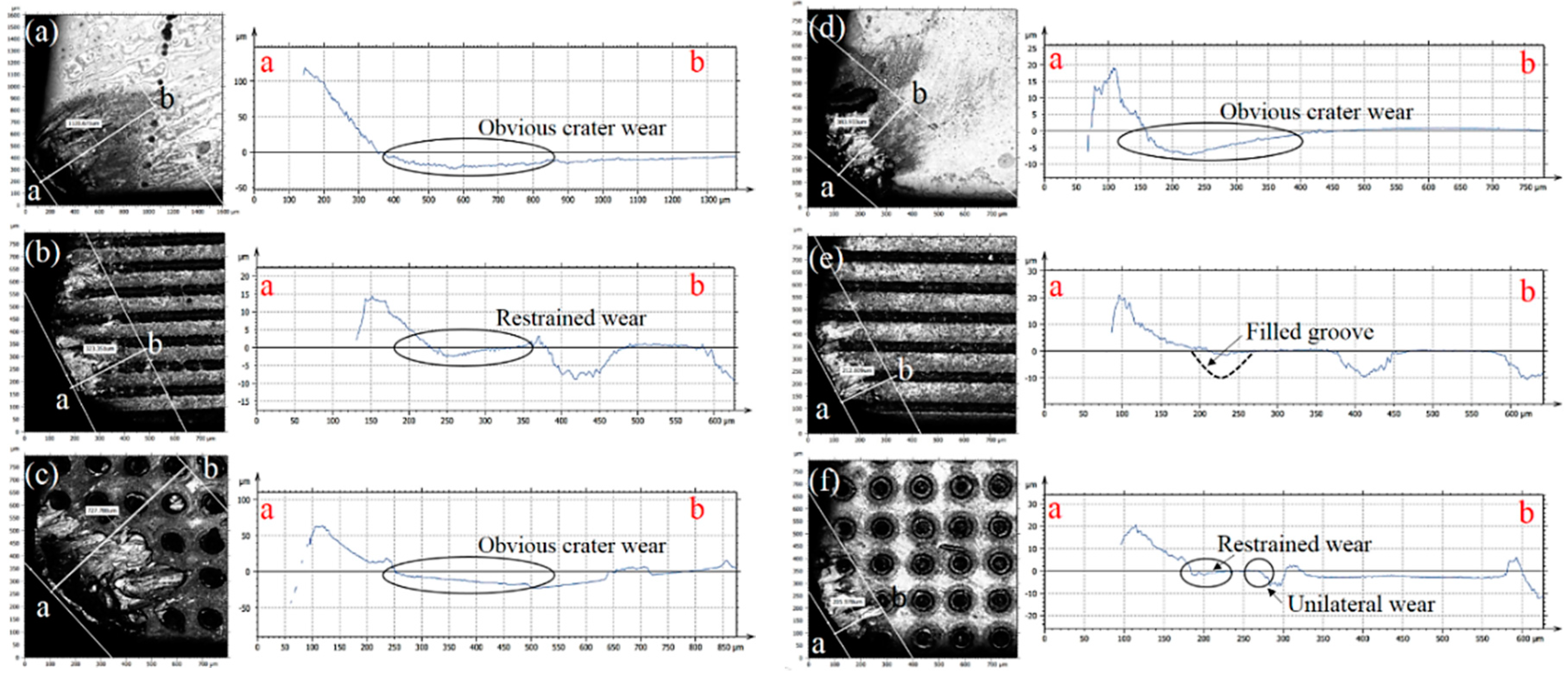
3.4. Wear and Adhesion on the Rake Face

Figure 8a,b shows the rake face adhesion of VLT tools at 200 and 50 m/min cutting speeds, respectively. The cutting depth, ap was 0.4 mm and feed rate f was 0.05 mm/r, cutting length was about 200 m. It can be seen that, at different speed, the shapes of adhesion were different. At the higher cutting speed, the adhesion layer was scattered while, as the cutting speed decreased, the adhesion layer was continuous and had a convex peak, modifying the tool shape and generating a negative rake angle.
Figure 9 presents the top-view and profiles of the tested tools’ rake faces (ab-line is the scan path of 2D profiles). The cutting length was 1400 m. After rough cutting, Figure 9a–c, various heights of the build-up edge (BUE, the height of the tool-chip adhesion), Hb, width of tool-chip contact (equal to the length of line-ab), Wc, and wear depth (the maximum value), Hw, can be observed on the rake faces. Note that the existence of MGT decreased Hb from 100 (flat tool) to 15 μm; meanwhile, the MGT tool also showed the minimum Wc and Hw among all three kinds of tools. Thus, MGT could be a better choice for promoting anti-wear performance in rough cutting.
After finish cutting (Figure 9d–f) with VLT and MGT tools, the BUE regions on their rake faces were half the size compared with the flat tool. However, the same BUE height, 20 μm, could be observed in all three tools. Crater wear of a maximum of 7 μm deep appeared on the non-textured rake face, while the maximum crater wear depth for the textured tools were inconspicuous, only 2 μm. This indicated an obvious promotion in anti-wear properties. In addition, a good durability of textured morphologies can be observed. For VLT morphology, the wear near the tool tip was unilateral. In the similar region of the MGT tool, the micro groove was filled with adhesive chip. The above analysis indicated that the failure modes of MGT and VLT were different in continuous cutting, that is, block and wear, respectively.

3.5. Chip Shape

Figure 10 presents the macro shape and micro morphology of chips generated in dry cutting. The chip formation is highly affected by the contact conditions at the tool-chip interface. It can be seen that the textured tools generated curlier chips in both cutting conditions, matching the previous analyses of the contact lengths. In finish cutting, VLT tool not only generated more curled chip compared with the nearly straight chip of flat tool, but also broke the chip evenly; this characteristic could avoid the machined surface being damaged by continuous chipping, benefitting the cutting precision and workpiece roughness. The chip produced by flat tools had smoother bottom surfaces compared with the textured tool chips. In rough cutting, the MGT reduced the formation of periodic cracks initiated at the free surface of the chip, while VLT had an opposite effect. In finish cutting, on the other hand, the VLT tool produced the smoothest chip compared to other two cases.

4. Conclusions

This study developed volcano-like textured (VLT) cutting tools by a laser re-melting process and compared it with micro-groove textured (MGT) tools in various cutting conditions, experimentally and theoretically. Some significant and specific results of this work are summarized below:
(1)
VLT tools showed lower cutting forces in rough cutting; in wet cutting, on the contrary, the cutting forces of VLT tools increased greatly compared to MGT and flat tools. The poor compatibility of coolant and VLT could be the main reason.
(2)
In finish cutting, VLT tools has similar tool-chip adhesion and contact length to MGT tools, while their failure modes were different, i.e., wear and blocking, respectively. The reduction proportion in contact length was nearly 50%. The depth of crater wear decreased from 7 to 2 μm, indicating an obvious promotion in wear-resistance.
(3)
The textured tools generated curlier chips compared to flat tools in finish cutting. VLT worked like a chip breaker, breaking the chip evenly. It also produced the smoothest chip compared to other tools.
(4)
VLT has better heat reduction effect on the rake face than MGT in roughing, and it is more likely to have an anti-adhesion effect in finish cutting. In addition, the distance between VLT and cutting edge should be carefully determined.

Author Contributions

Conceptualization, Z.K. and Y.F.; Investigation, Z.K.; Methodology, Z.K.; Project administration, Y.F. and M.B.-G.J.; Software, X.F.; Supervision, Y.F. and M.B.-G.J.; Writing—review and editing, Z.K. and X.F.

Funding

This research was funded by Science and Finance Departments in Jiangsu Province, China [BE2016144].

Acknowledgments

The first author wants to give special acknowledgement to the China Scholarship Council (CSC) for providing the financial support from July, 2017 to June 2018 (No. 201708320234) and to the prominent research conditions at Purdue campus.

Conflicts of Interest

The authors declare no conflict of interest.

References

  1. Arslan, A.; Masjuki, H.H.; Kalam, M.A.; Varman, M.; Mufti, R.A.; Mosarof, M.H.; Khuong, L.S.; Quazi, M.M. Surface texture manufacturing techniques and tribological effect of surface texturing on cutting tool performance: A review. Crit. Rev. Solid State Mater. Sci. 2016, 41, 447–481. [Google Scholar] [CrossRef]
  2. Sharma, V.; Pandey, P.M. Recent advances in turning with textured cutting tools: A review. J. Clean. Prod. 2016, 137, 701–715. [Google Scholar] [CrossRef]
  3. Etsion, I. State of the Art in Laser Surface Texturing. J. Tribol. 2005, 127, 761–762. [Google Scholar] [CrossRef]
  4. Jiang, X.J.; Whitehouse, D.J. Technological shifts in surface metrology. CIRP Ann. Manuf. Technol. 2012, 61, 815–836. [Google Scholar] [CrossRef]
  5. Enomoto, T.; Watanabe, T.; Aoki, Y.; Ohtake, N. Development of a Cutting Tool with Micro Structured Surface. Trans. Jpn. Soc. Mech. Eng. 2007, 73, 288–293. [Google Scholar] [CrossRef]
  6. Kawasegi, N.; Sugimori, H.; Morimoto, H.; Morita, N.; Hori, I. Development of cutting tools with microscale and nanoscale textures to improve frictional behavior. Precis. Eng. 2009, 33, 248–254. [Google Scholar] [CrossRef]
  7. Lei, S.; Devarajan, S.; Chang, Z. A study of micropool lubricated cutting tool in machining of mild steel. J. Mater. Process. Technol. 2009, 209, 1612–1620. [Google Scholar] [CrossRef]
  8. Fatima, A.; Mativenga, P.T. Assessment of tool rake surface structure geometry for enhanced contact phenomena. Int. J. Adv. Manuf. Technol. 2013, 69, 771–776. [Google Scholar] [CrossRef]
  9. Obikawa, T.; Kamio, A.; Takaoka, H.; Osada, A. Micro-texture at the coated tool face for high performance cutting. Int. J. Mach. Tools Manuf. 2011, 51, 966–972. [Google Scholar] [CrossRef]
  10. Sugihara, T.; Enomoto, T. Improving anti-adhesion in aluminum alloy cutting by micro stripe texture. Precis. Eng. 2012, 36, 229–237. [Google Scholar] [CrossRef]
  11. Chang, W.; Sun, J.; Luo, X.; Ritchie, J.M.; Mack, C. Investigation of microstructured milling tool for deferring tool wear. Wear 2011, 271, 2433–2437. [Google Scholar] [CrossRef]
  12. Sugihara, T.; Enomoto, T. Crater and flank wear resistance of cutting tools having micro textured surfaces. Precis. Eng. 2013, 37, 888–896. [Google Scholar] [CrossRef]
  13. Xie, J.; Luo, M.J.; Wu, K.K.; Yang, L.F.; Li, D.H. Experimental study on cutting temperature and cutting force in dry turning of titanium alloy using a non-coated micro-grooved tool. Int. J. Mach. Tools Manuf. 2013, 73, 25–36. [Google Scholar] [CrossRef]
  14. Sugihara, T.; Enomoto, T. Development of a cutting tool with a nano/micro textured surface-Improvement of anti-adhesive effect by considering the texture patterns. Precis. Eng. 2009, 33, 425–429. [Google Scholar] [CrossRef]
  15. Dong, M.K.; Lee, I.; Sun, K.K.; Bo, H.K.; Park, H.W. Influence of a micro patterned insert on characteristics of the tool-workpiece interface in a hard turning process. J. Mater. Process. Technol. 2015, 229, 160–171. [Google Scholar]
  16. Kang, Z.; Fu, Y.; Ji, J.; Tian, L. Numerical investigation of microtexture cutting tool on hydrodynamic lubrication. J. Tribol. 2017, 139, 054502. [Google Scholar] [CrossRef]
  17. Ivanović, L.; Vencl, A.; Stojanović, B.; Marković, B. Biomimetics design for tribological applications. In Proceedings of the 15th International Conference on Tribology, Kragujevac, Serbia, 17–19 May 2017. [Google Scholar]
  18. Bhushan, B.; Yong, C.J. Natural and biomimetic artificial surfaces for superhydrophobicity, self-cleaning, low adhesion, and drag reduction. Prog. Mater. Sci. 2011, 56, 1–108. [Google Scholar] [CrossRef]
  19. Parker, A.R.; Lawrence, C.R. Water capture by a desert beetle. Nature 2001, 414, 33–34. [Google Scholar] [CrossRef] [PubMed]
  20. Ridgway, S.H.; Carder, D.A. Features of dolphin skin with potential hydrodynamic importance. IEEE Eng. Med. Biol. 1993, 12, 83–88. [Google Scholar] [CrossRef] [Green Version]
  21. Xing, Y.; Deng, J.; Zhao, J.; Zhang, G.; Zhang, K. Cutting performance and wear mechanism of nanoscale and microscale textured Al2O3/TiC ceramic tools in dry cutting of hardened steel. Int. J. Refract. Met. Hard Mater. 2014, 43, 46–58. [Google Scholar] [CrossRef]
  22. Koshy, P.; Tovey, J. Performance of electrical discharge textured cutting tools. CIRP Ann. Manuf. Technol. 2011, 60, 153–156. [Google Scholar] [CrossRef]
  23. Xie, J.; Luo, M.J.; He, J.L.; Liu, X.R.; Tan, T.W. Micro-grinding of micro-groove array on tool rake surface for dry cutting of titanium alloy. Int. J. Precis. Eng. Manuf. 2012, 13, 1845–1852. [Google Scholar] [CrossRef]
  24. Du, D.; He, Y.F.; Sui, B.; Xiong, L.J.; Zhang, H. Laser texturing of rollers by pulsed Nd: YAG laser. J. Mater. Process. Technol. 2005, 161, 456–461. [Google Scholar] [CrossRef]
  25. Ma, J.F.; Duong, N.H.; Lei, S. Numerical investigation of the performance of microbump textured cutting tool in dry machining of AISI 1045 steel. J. Manuf. Process. 2014, 19, 194–204. [Google Scholar] [CrossRef]
  26. Zhang, Y.; Wang, X.; Li, H.; Wang, B. Adhesive behavior of micro/nano-textured surfaces. Appl. Surf. Sci. 2015, 329, 174–183. [Google Scholar] [CrossRef]
  27. Kang, Z.Y.; Fu, Y.H.; Ji, J.H.; Wang, H. Characterisation of group behavior surface texturing with multi-layers fitting method. Nondestruct. Test. Eval. 2016, 31, 235–246. [Google Scholar] [CrossRef]
  28. Xing, Y.; Deng, J.; Feng, X.; Yu, S. Effect of laser surface texturing on Si3N4/Tic ceramic sliding against steel under dry friction. Mater. Des. 2013, 52, 234–245. [Google Scholar] [CrossRef]
  29. Arulkirubakaran, D.; Senthilkumar, V.; Kumawat, V. Effect of micro-textured tools on machining of Ti-6Al-4V alloy: An experimental and numerical approach. Int. J. Refract. Met. Hard Mater. 2016, 54, 165–177. [Google Scholar] [CrossRef]
  30. Zhang, Y.C.; Mabrouki, T.; Nelias, D.; Gong, Y.D. Chip formation in orthogonal cutting considering interface limiting shear stress and damage evolution based on fracture energy approach. Finite Elem. Anal. Des. 2011, 47, 850–863. [Google Scholar] [CrossRef]
  31. Johnson, G.C.; Bammann, D.J. Discussion of stress rates in finite deformation problems. Int. J. Solids Struct. 1984, 20, 725–737. [Google Scholar] [CrossRef]
  32. Kümmel, J.; Braun, D.; Gibmeier, J.; Schneider, J.; Greiner, C.; Schulze, V. Study on micro texturing of uncoated cemented carbide cutting tools for wear improvement and built-up edge stabilization. J. Mater. Process. Technol. 2015, 215, 62–70. [Google Scholar] [CrossRef]
  33. Rao, P.N. Manufacturing Technology: Metal Cutting and Machine Tools, 3rd ed.; McGraw-Hill Education: New York, NY, USA, 2013; Volume 2. [Google Scholar]
Figure 1. The actual size of the micro-groove texture (MGT) tool (a) volcano-like texture (VLT) rake face; (b) cross-section of VLT; (c) MGT rake face; (d) 3-D micrographs of MGT.
Lubricants 06 00098 g001
Figure 2. Orthogonal cutting experiment and parameters of tools and cutting experiments.
Lubricants 06 00098 g002
Figure 3. The FEM model and grid structure referred in this study.
Lubricants 06 00098 g003
Figure 4. Variation in main cutting forces with machining time in FEM simulation, (a) roughing; (b) finishing; (c) comparison of cutting force between experimental and simulative results.
Lubricants 06 00098 g004
Figure 5. Stress and temperature fields distribution on rake face. (a) roughing, (b) finishing.
Lubricants 06 00098 g005
Figure 6. Forming process of the adhesion layer of a VLT tool.
Lubricants 06 00098 g006
Figure 7. (a) Cutting forces in rough cutting; (b) Cutting forces in finish cutting; (c) Cutting forces of VLT tools at two cutting speeds; (d) Cutting forces decline with applying a coolant.
Lubricants 06 00098 g007
Figure 8. The wear morphology of the convex textured rake face at (a) 200 m/min, and (b) 50 m/min cutting speed.
Lubricants 06 00098 g008
Figure 9. Rake face wear of tested cutting tools; line-ab is the scan path of 2D profiles; left column (ac): rough cutting; right column: finish cutting. (a,d) flat tools; (b,e) MGT tools; (c,f) VLT tools.
Lubricants 06 00098 g009
Figure 10. Micro and macro shape of the chip. N: flat; G: MGT; V: VLT; r: roughing; f: finishing.
Lubricants 06 00098 g010
Table 1. Parameters of surface texturing.
TypesWidth wg [μm]Depth hg [μm]Spacing sg [μm]Area Density ρg [%] 1
Flat----
MGT501012030
VLTDiameter dv [μm]Height hv [μm]Spacing sv [μm]Area density ρv [%] 2
90318020
1ρg = wg/(wg + sg); 2 ρv = πdv2/4 sv; values are rounded.
Table 2. Johnson-Cook parameters of A6061.
A [Mpa]B [Mpa]mCnTm [°C]T0 [°C]
3241141.340.0020.4261020
Table 3. Basic mechanical and thermal properties of the A6061 and YG6.
Physical ParametersA6061YG6
Density, ρ [kg/m3]270015,290
Elastic modulus, E [GPa]70600
Poisson’s ratio, ν0.330.23
Specific heat, Cp [J/kg/°C]896178
Thermal conductivity, λ [W/m/°C]17324
Thermal expansion coefficient, α [μm/m/°C]23.55

