Abstract
An understanding of mechanisms which are responsible for elastohydrodynamic lubricant film formation under high sliding conditions is necessary to increase durability of machine parts. This work combines thin-film colorimetric interferometry for lubricant film thickness measurement and infrared microscopy for in-depth temperature mapping through the contact. The results describe the effect of operating conditions such as speed, slide-to-roll ratio, ambient temperature, and sliding direction on lubricant film thickness and temperature distribution. Film thickness data shows how much the film shape is sensitive to operating conditions when thermal effects are significant, while the temperature profiles provides an explanation of this behavior.
1. Introduction
Elastohydrodynamic lubrication (EHL) is a regime of fluid-film lubrication of concentrated contacts, where a high contact pressure causes significant change in lubricant viscosity and surface deformations are of the same order as lubricant film thickness. Many machine elements—such as gears, rolling element bearings, cam/follower systems, etc.—are designed to operate in this regime thanks to relatively low friction. EHL film thickness prediction plays an important role in the design of high performance tribological systems.
A classic isothermal EHL theory was established based on numerical work of Hamrock and Dowson [1] together with experimental work of Gohar and Cameron [2]. This theory is widely applied in engineering practice since 1960s. Subsequently, the focus has been extended to rolling–sliding conditions [3,4]. It was stated that additional shearing in lubricant contributes to increase in contact temperature and has other shear-induced effects such as shear thinning [5,6]. These thermal and non-Newtonian effects lead to the reduction in lubricant film thickness [3,4,5,6]. For relatively low slide-to-roll ratio this reduction is uniform, however under high sliding conditions, lubricant film shape changes significantly.
One of the most significant phenomena is a local increase in film thickness in central zone so-called ‘dimple’. This phenomenon was first described by Kaneta and his co-workers under pure sliding conditions [7,8]. Using a ball-on-disc tribometer and optical interferometry, they have found that this unpredictable film shape occurs when glass disc slides against steel ball but not in the opposite case. These findings contradict commonly accepted view that film thickness is basically dependent on conditions in the inlet region. In recent years, this effect was studied experimentally by several authors [7,8,9,10,11,12,13]. It has been found that this effect is dependent mainly on kinematic conditions, material properties, and rheology of lubricant. Further study suggested that mainly a thermal conductivity of contacting surfaces is of great importance in dimple formation [10,14].
During last decades, several models have been proposed to explain the dimple phenomena. Some of them assume surface deformation under isothermal conditions such as “squeeze film effect” [7] and “surface-stretch mechanism” [15]. Others expect non-Newtonian behavior of lubricant such as “boundary slippage” [16], “limiting shear stress” [17], or “plug flow model” of solidified lubricant [18]. Due to high shear rates in EHL thermal models seems to be much more relevant. Nowadays, one of the most accepted thermal models is temperature–viscosity wedge effect [10,11,12].
Further insight into the problem has been made possible by the development of temperature mapping using infrared microscopy based on the approach developed by Ausherman et al. [19]. IR technique was applied by Spikes et al. [20,21] and further improved by Reddyhoff et al. [22,23], Le Rouznic et al. [24], and Lu et al. [25]. Yagi, Nakahara et al. [26,27,28] used infrared microscopy for temperature mapping of the contact under high sliding conditions where the dimple occurs. They showed that the dimple phenomena could be explained by the temperature-viscosity wedge effect. Moreover, they reported an increase in oil temperature at the top of the dimple. Similar results were published by Bruyer [29], who focused on numerical simulation of a line contact using Navier–Stokes equations. Other works on numerical simulation of EHL contact uses modified Reynolds equations or CFD model [30,31,32,33].
Recently, Omasta et al. [34,35] studied lubricant film thickness distribution under the conditions, where the rolling and the sliding velocity has different direction. They found that the direction significantly influences film shape once the sliding speed and related thermal effects are large enough. An asymmetry of the film shape under high sliding conditions was found although the kinematic conditions were symmetrical. Those conditions are interesting, especially when sliding is perpendicular to the rolling. This situation could allow to distinguish the effect of sliding and rolling speed and to provide better evidence of the mechanism responsible for the film shape changes connected with the sliding. Nevertheless, temperature mapping under the conditions has not been made yet.
The aim of this paper is to describe the effect of sliding velocity on lubricant film thickness with respect to the temperature distribution in EHL contact. Attention is paid to the influence of sliding speed direction. For these purposes, IR technique for temperature mapping is implemented and used together with lubricant film thickness measurement.
2. Materials and Methods
2.1. Optical Tribometer
The experiments were performed with the optical ball-on-disc tribometer (Brno University of Technology, Brno, Czech Republic) that is illustrated in Figure 1. Sapphire disc with a diameter of 140 mm and a thickness of 5 mm is loaded using a death-weight lever mechanism against AISI 52100 steel ball with a diameter of 25.4 mm. Both the ball and the disc are independently driven by electric motor to provide a rolling–sliding contact.
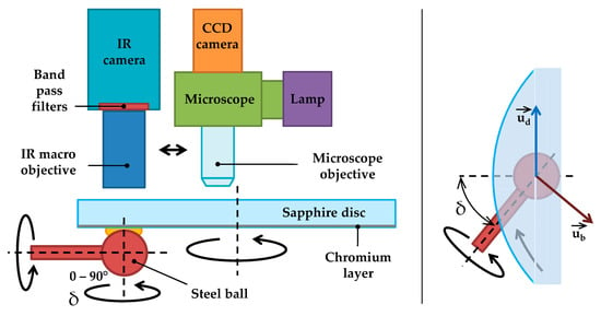
Figure 1.
Scheme of the ball-on-disc tribometer for IR microscopy and optical interferometry.
The ball and its drive can be inclined around a contact normal in the range from 0° to 90°. The angle is referred to as δ angle, as indicated in Figure 1. This inclination results in different direction of the ball and the disc velocities. By reversing the direction of rotation of the ball, the angle between surface velocities of 90° to 180° can be achieved.
Entrainment velocity is expressed as half of the vector addition using the formula
where and are velocities of the ball and the disc respectively. Sliding velocity is defined as vector difference according to the formula
The slide-to-roll ratio (SRR) is expressed as a ratio between magnitudes of sliding and entrainment velocity by the formula
The angle between sliding and entrainment velocities is defined as ε angle. For ε = 0° entrainment and sliding has the same direction. For ε = 90°, sliding is perpendicular to entrainment. The velocities are graphically indicated in Figure 2. Interferograms and film thickness and temperature results in this study are oriented so that the entrainment direction corresponds to the x-axis.
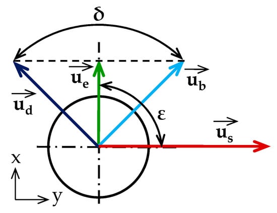
Figure 2.
Scheme of the ball-on-disc tribometer for IR microscopy and optical interferometry.
The contact is lubricated with FVA 4 oil by dipping the ball in the lubricant reservoir. This lubricant is ISO VG 460 base mineral oil that is used as reference gear oil [36]. The properties of the ball and disc material and the oil are shown in Table 1.

Table 1.
Mechanical and physical properties of the contacting bodies and the lubricant.
2.2. Measurement Techniques
This work utilizes two experimental techniques: thin film colorimetric interferometry (TFCI) for lubricant film thickness measurement and infrared (IR) microscopy for temperature mapping. TFCI method developed by Hartl et al. [37] uses white light interferometry with color matching algorithm and CIELAB color-film thickness calibration. The contact between the steel ball and the sapphire disc with thin chromium layer is captured by a CCD camera attached to the industrial microscope. Halogen lamp is used as a light source. For the measurement, calibration, and evaluation of interferograms AChILES software (Brno University of Technology) was used.
IR microscopy senses electromagnetic waves in the IR radiation range. In the study FLIR SC5000 camera (FLIR Systems, Wilsonville, OR, USA) with IR macro objective were used. Determination of temperature distribution of both contacting surfaces and oil film is allowed by a combination of measurement procedure and robust calibration.
The scheme of the measurement procedure is depicted in Figure 3. Radiation of the contact is composed of radiation of the steel ball, the disc and the lubricant. Two band filters referred to as L and S filter and disc with and without a chromium layer were used to separate individual components of radiation. The L filter transmits the radiation of the steel ball only while the S filter transmits the radiation of both the ball surface and the lubricant volume. In both cases, a sapphire disc without coating is used. When the L filter is used with the sapphire disc having a thick chromium layer on a contact side, only a radiation of disc surface is dominant.

Figure 3.
Scheme of the radiation components in the contact.
Since the IR camera data is expressed as counts, calibration under the given temperatures and in various configurations is required. The calibration was performed using separate device, where the ball is loaded against a sapphire window with and without chromium layer. The ball in the static Hertzian contact is heated up to 250 °C and the contact temperature is measured using a precise thermocouple. The results of the calibration are graphs showing IR radiation (expressed as a digital level detected by the camera sensor) as a function of contact temperature. These graphs include various combinations of the disc and filter that are used during the measurement to distinguish the ball, the disc, and oil temperature. The calibration also includes determination of the effect of lubricant film thickness on its radiation. For this purpose, oil radiation and corresponding film thickness under given temperature is evaluated in the gap around the static Hertzian contact. The effect of the lubricant film thickness on its temperature is expressed as a hyperbolic function that is in accordance with Lu et al. [25]. For the calibration, measurement, and evaluation of temperature maps the ATILA software (Brno University of Technology) was developed and used.
2.3. Experimental Conditions
A series of experiments was designed to address the effect of speed, slide-to-roll ratio (SRR), ambient temperature and rolling to sliding velocity inclination. All the experiments were carried out at a load F = 76 N that corresponds to the Hertzian pressure pH = 1.2 GPa. Ambient temperature t was set to 30 °C and 60 °C. The temperature was controlled by heating the tribometer body while the working area of the tribometer was covered and the tribometer ran under pure-rolling. Our own measurements followed this procedure once the inlet temperature as well as the surface temperature of contacting bodies stabilized at the required level. This procedure ensures uncertainty in the surface temperature of contacting bodies of about 1 °C at 60 °C.
Three levels of entrainment speed ue were selected: 50, 100, and 150 mm/s at 30 °C. At the temperature of 60 °C the speeds were recalculated with respect to the changed oil viscosity, so that the product of entrainment speed and oil viscosity (ue × η0) at a given temperature is constant. Thus, lubricant film thickness under pure rolling should be the same with respect to the isothermal EHL theory. Resulting speeds for 60 °C are 317, 634, and 951 mm/s. SRR of 2.5 and 5 was chosen to draw the thermal effects. In both cases, there is a partial opposite sliding, which means that surfaces moves against each other. SRR is positive, so the speed of the ball is higher than the speed of the disc. To show the effect of the angle between entrainment and sliding velocity, two extreme cases were investigated: ε angle of 0° that represents coincidence rolling and sliding and ε angle of 90° where the entrainment velocity is perpendicular to the sliding velocity while the magnitudes of surface velocities were the same. These conditions are hereinafter referred to as longitudinal and lateral sliding.
3. Results
3.1. Lubricant Film Thickness Data
Optical interferograms of all the conditions analyzed in this study are summarized in Figure 4. These interferograms show the effect of speed, ambient temperature, SRR, and rolling to sliding inclination. For all the conditions lubricant film thickness data are evaluated in graphs in Figure 5. These three graphs show lubricant film thickness in a dimple, inlet film thickness, and minimum film thickness as a function of operating conditions. The dimple film thickness represents the largest film thickness that occurs in a dimple in central zone. Inlet film thickness should represent a central film thickness unaffected by the dimple. For dimpled film shape this is the smallest film thickness in the inlet or central part of the contact at y = 0 (axis of symmetry of the inteferograms). Minimum film thickness is a global minimum that occurs usually in side lobes.
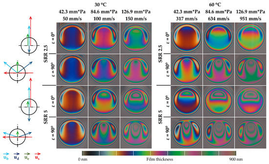
Figure 4.
Color interferograms and an approximate color vs. lubricant film thickness scale under various contact conditions.
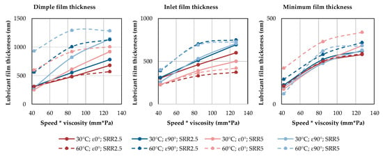
Figure 5.
The graphs showing lubricant film thickness in a dimple, inlet film thickness, and minimum film thickness as a function of operating conditions corresponding to the interferograms in Figure 4.
The results show that overall lubricant film thickness increases with speed. The effect of other parameters is however much less predictable. Except for low speed and low SRR at 30 °C the film shape is significantly affected by the dimple.
The effect of sliding direction is very interesting. For low speed with SRR 2.5 and 30 °C the effect is negligible, and this state could be termed as isothermal. As the speed or temperature increases, lateral sliding leads to thicker film compared to longitudinal sliding. At 60 °C and SRR 2.5 inlet film thickness is almost double for lateral sliding. There is also a significant increase in minimum film thickness. For SRR 5 the effect is similar in the case of central film thickness. On the other hand, minimum film thickness may decrease for lateral sliding as the dimple becomes narrow in the entrainment direction. This is evident at SRR 5 for low speed and 60 °C, where the minimum film thickness under lateral sliding is roughly one-quarter of the thickness for longitudinal sliding.
The effect of SRR is also non-uniform. Generally, overall film thickness reduction is supposed with increasing SRR. This is the true for low speed at 30 °C, until the dimple begins to appear. Then the effect depends on sliding direction and other parameters. When the sliding is lateral, the effect is usually positive for central film thickness and negative for minimum film thickness due to the dimple shape. For longitudinal sliding, the effect is rather a negative for lower temperature and positive for higher temperature. It is also interesting that a minimum film thickness is significantly improved by longitudinal sliding at 60 °C. Minimum film thickness in side lobes is about twice as large for higher SRR.
The effect of ambient temperature relates to the speed normalized with respect to the changed viscosity. The speed enhances thermal phenomena that are responsible for the dimple effect. Therefore, the effect of ambient temperature on lubricant film thickness is mostly positive thanks to the dimple.
3.2. Temperature Profiles
An analysis of temperature distribution was made for selected cases summarized in Figure 4. The effect of SRR for the high speed and longitudinal sliding at 30 °C is depicted in graphs in Figure 6. These graphs describe film thickness profile and the oil, disc, and ball temperature profiles. The high SRR case increases oil temperature and surface temperatures with 30 and 20 degrees more than the low SRR case. Higher SRR also inclines temperature profiles in the direction of surface movement. Since the ball is faster, the oil temperature is inclined in the direction of the ball. The difference in inlet zone is app. 15 °C. For the low SRR, the oil and the disc temperature profiles are nearly symmetrical while the ball temperature profile is slightly inclined in the direction of its movement. Despite the symmetrical oil temperature profile, the small dimple just before the exit constriction exists.
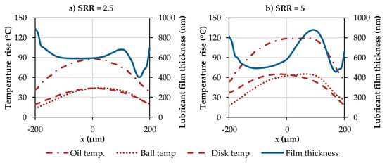
Figure 6.
The graphs showing the effect of SRR on lubricant film thickness and temperatures in longitudinal profiles at y = 0 (t = 30 °C; ε = 0°; high speed, ue = 150 mm/s; pH = 1.2 GPa): (a) SRR = 2.5; (b) SRR = 5.
The effect of ambient temperature and the speed normalized with respect to changed viscosity is shown in Figure 7, where oil temperature and lubricant film thickness profiles are compared. It is evident that the increase in ambient temperature increases oil temperature rise, while the shape of temperature profile seems to be similar. Despite, there is a significant change in lubricant film shape at low speed. The dimple occurring at 60 °C is not reflected in the corresponding oil temperature profile. At high speed, the dimple occurs in both the cases and shape of the oil temperature profile is similar, i.e., inclined in the entrainment direction.
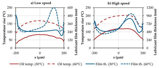
Figure 7.
The graphs showing the effect of ambient temperature and normalized entrainment speed on lubricant film thickness and oil temperature in longitudinal profiles at y = 0 (ε = 0°; SRR = 5; pH = 1.2 GPa): (a) Low speed (ue × η0 = 42.3 mm·Pa); (b) High speed (ue × η0 = 126.9 mm·Pa).
The results for lateral sliding are described in Figure 8 and Figure 9. The first one compares film thickness and temperature profiles in entrainment direction for low and high speed at 30 °C and high SRR. These results can be compared with the corresponding results under longitudinal sliding to assess the effect of sliding velocity inclination. Figure 8a corresponds to Figure 7a and Figure 8b corresponds to Figure 6b. The results for longitudinal sliding are plotted in light colors in Figure 8. At low speed, lateral sliding causes a slightly thicker film with a tiny dimple just before the exit constriction. Oil temperature profile is more symmetrical with respect to the y-axis and profiles of the temperature of the contacting bodies are predominantly coincident.
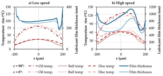
Figure 8.
The graphs showing the effect of normalized entrainment speed on lubricant film thickness and temperatures in longitudinal profiles at y = 0 (t = 30 °C; ε = 90°; SRR = 5; pH = 1.2 GPa): (a) Low speed (ue × η0 = 42.3 mm·Pa); (b) High speed (ue × η0 = 126.9 mm·Pa). The profiles in light colors represent corresponding results for ε = 0°.
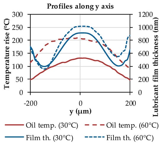
Figure 9.
The graphs showing the effect of ambient temperature on lubricant film thickness and oil temperature in lateral profiles at x = 0 (ε = 90°; pH = 1.2 GPa; high speed, ue × η0 = 126.9 mm·Pa).
Under the high speed conditions lateral sliding leads to significantly larger lubricant film thickness in the whole profile with a dimple elongated towards inlet region. The oil temperature is higher in the central part while the temperatures of contacting bodies are slightly lower. The ball temperature profiles for both sliding directions are coincident in the input half of the contact; then the temperature under longitudinal sliding is higher and reaches maximum in the exit half of the contact. The same applies to the disc temperature.
Lubricant film thickness and the oil temperature profiles in lateral direction are compared for the low and the high temperature in Figure 9. At low temperatures, film thickness and temperature profiles along the sliding direction are symmetrical with respect to the x-axis; however, at high temperature the minimum film thickness is lower in the disc velocity direction. The same asymmetry occurs also in the oil temperature, where the profile is stretched in sliding direction.
4. Discussion
Lubricant film thickness is one of the most important parameters defining the ability of the contact to carry load without direct interaction of mating surfaces. The data described in Section 3.1 reveals that the dimple phenomenon significantly affects lubricant film thickness distribution in almost all the cases, which was studied. It is evident that even a small change in operating conditions may increase or decrease lubricant film thickness significantly. For example, the change in SRR from 2.5 to 5 may increase the minimum film thickness by 100%. This finding is of high practical relevance since the mechanical properties of the sapphire–steel contact are very close to the real steel–steel configuration.
In this study, the influencing parameters are SRR, sliding direction and ambient temperature; other important parameters are thermal properties of the contacting bodies. These effects could be considered in the design of machine parts; nevertheless, the current possibilities of lubricant film thickness prediction under these conditions are limited. Although the conditions are specific, they are of great significance in machine components such as cam–tappet mechanisms and retainerless rolling element bearings.
It is obvious that thermal effects play an important role under the high sliding conditions. A surface entering the contact area has a low temperature corresponding to the ambient temperature. Then, it is heated predominantly due to compress and viscous work while the heat generated in the central region depends mainly on load, sliding speed, and lubricant film strength that is a function of its viscosity influenced by the pressure and temperature. The generated heat is dissipated through conduction to the contact bodies, so the heat partitioning between the surfaces in the contact conjunction is mainly controlled by thermal properties. The temperature increase is larger on the surface, having lower thermal conductivity.
The dimple occurrence can be ascribed to the temperature–viscosity wedge effect. This effect assumes unequal temperature distribution across film thickness which results in different viscosity wedges in different parts of the contact. When these wedges move against each other, additional pressure is induced and thus the dimple occurs. This is revealed especially by the profiles of the ball and the disc temperature, which are inclined in the direction of movement. This inclination is insignificant at low speed, where the dimple does not occur. At high speed, this inclination makes a difference between the ball and the disc surface temperature at contact inlet zone (Figure 6). For a lateral sliding, the difference is lower at the entrainment direction (Figure 8).
Nevertheless, there are some findings that deserve a discussion. The results in Figure 7a indicate that the dimple formation may not be related to the change in the shape of the oil temperature profile. The two oil temperature profiles in Figure 7a have the same shape and differ only quantitatively, although in the first case there is no dimple while in the second the dimple thickness is 2.5 times larger than the inlet film thickness.
Some qualitative contradiction can be found with [10,38] where the dimple formation under the opposite sliding was also investigated based on temperature measurement. In these works, a very marked rise in the oil temperature in the dimple was observed. In the current work the oil radiation level detected by IR camera is also much larger in the dimple; however, once the effect of higher lubricant film thickness in the dimple is compensated based on calibration curves, the oil temperature profile does not show a steep rise in the dimple. The temperature profiles in the dimple could provide some information about the state of the oil in the dimple. If the oil rotates in the dimple, its temperature should be higher. If the oil is sheared in one or more planes, then the increase may not be significant. If there is a boundary slippage only on one of the surfaces, then the temperature of the surface should be significantly higher. CFD-based solution that considers continues change in oil speed profile through the film thickness made in [29] indicates only a moderate and gradual rise in the oil temperature under the high SRR. Further research is expected on this topic.
The effect of sliding direction on lubricant film shape is in qualitative accordance with the previous study [35]. Sliding inclination changes the shape of the dimple. The dimple is produced by the temperature–viscosity wedge action of the counter surfaces. This sliding velocity component is often called zero entrainment velocity (ZEV) [10,38,39,40,41]. The dimple produced under ZEV conditions is usually narrowed in sliding direction and becomes circular with increasing speed [41]. The dimple thickness under ZEV conditions increases with speed to a certain limit from which it decreases. Under the arbitrary rolling–sliding the entrainment, the velocity component forces and deforms the dimple in the entrainment direction and changes heat flow through the contact. Under lateral sliding, temperature gradients appear in the lateral direction, so the difference in the ball and the disc temperature profiles is lower in Figure 8. The surface temperatures under longitudinal sliding are slightly higher. This can be related to the heat flow through the contact, particularly how the inlet region is heated by the surface moving in opposite direction. Under lateral sliding, the impact on the inlet viscosity should be smaller.
Asymmetry in lateral film thickness and oil temperature profiles in Figure 9 can be attributed to the lower thermal conductivity of sapphire compared to steel, as listed in Table 1. This effect is relatively low compared to glass disc that is usually used in optical tribometers. As the speed and the generated heat increases, the asymmetry is much more pronounced. There is a reasonable explanation in that more heat results in more significant difference in temperature. Moreover, the thermal conductivity of single crystal sapphire decreases with temperature in the relevant temperature range. Lower thermal conductivity of the disc results in higher oil temperature in the direction of the disc movement and the asymmetry is more significant.
5. Conclusions
This work describes, for the first-time, temperature distribution in the contact with different entrainment and sliding velocity direction. Based on the temperature and lubricant film thickness measurements, the following conclusions can be drawn:
- Under high sliding conditions, lubricant film thickness is very sensitive to the operating conditions due to the dimple phenomenon. Particularly, ambient temperature, SRR, and sliding direction could significantly improve central as well as minimum lubricant film thickness.
- There is no direct connection between temperature or its gradient and dimple occurrence.
- This study reveals a less significant temperature increase in a dimple than other experimental works.
- Asymmetry in lubricant film thickness under lateral sliding relates to temperature distribution affected by different thermal conductivity of contacting bodies. This observation is in accordance with the temperature–viscosity wedge effect.
Author Contributions
Conceptualization, M.O. and P.S.; Methodology, M.O.; Software, P.S. and I.K.; Validation, P.S. Formal analysis, J.A.; Investigation, J.A. and M.O.; Writing—original draft preparation, M.O.; Writing—review and editing, P.S.; Supervision, I.K.; Project administration, M.H.
Funding
This research was funded by the Czech Science Foundation (GACR), grant number 15-24091S, and the Ministry of Education, Youth and Sports of Czech Republic under the National Sustainability Program I, project number LO1202.
Conflicts of Interest
The authors declare no conflict of interest. The funders had no role in the design of the study; in the collection, analyses, or interpretation of data; in the writing of the manuscript, or in the decision to publish the results.
References
- Dowson, D.; Higginson, G.R.; Whitaker, A.V. Elasto-Hydrodynamic Lubrication: A Survey of Isothermal Solutions. J. Mech. Eng. Sci. 1962, 4, 121–162. [Google Scholar] [CrossRef]
- Gohar, R.; Cameron, A. Optical Measurement of Oil Film Thickness under Elasto-Hydrodynamic Lubrication. Nature 1963, 200, 458–459. [Google Scholar] [CrossRef]
- Wilson, W.R.D.; Sheu, S. Effect of inlet shear heating due to sliding on elastohydrodynamic film thickness. J. Lubr. Technol. 1983, 105, 187–188. [Google Scholar] [CrossRef]
- Lord, J.; Larsson, R. Effects of slide-roll ratio and lubricant properties on elastohydrodynamic lubrication film thickness and traction. Proc. Inst. Mech. Eng. Part J J. Eng. Tribol. 2001, 215, 301–308. [Google Scholar] [CrossRef]
- Bair, S. Shear thinning correction for rolling/sliding elastohydrodynamic film thickness. Proc. Inst. Mech. Eng. Part J J. Eng. Tribol. 2005, 219, 69–74. [Google Scholar] [CrossRef]
- Kumar, P.; Khonsari, M.M. EHL circular contact film thickness correction factor for shear-thinning fluids. J. Tribol. 2008, 130, 041506–041513. [Google Scholar] [CrossRef]
- Kaneta, M.; Nishikawa, H.; Kameishi, K.; Sakai, T.; Ohno, N. Effects of elastic moduli of contact surfaces in elastohydrodynamic lubrication. J. Tribol. 1992, 114, 75–80. [Google Scholar] [CrossRef]
- Kaneta, M.; Nishikawa, H.; Kanada, T.; Matsuda, K. Abnormal Phenomena Appearing in EHL Contacts. J. Tribol. 1996, 118, 886–893. [Google Scholar] [CrossRef]
- Kaneta, M. For the establishment of a new EHL theory. Tribol. Ser. 1999, 36, 25–36. [Google Scholar]
- Yagi, K.; Kyogoku, K.; Nakahara, T. Mechanism of Dimple Formation under Elastohydrodynamic Conditions. Tribol. Ser. 2003, 41, 111–120. [Google Scholar]
- Yagi, K.; Vergne, P.; Nakahara, T. In situ pressure measurements in dimples elastohydrodynamic sliding contacts by Raman microspectroscopy. Trans. Tribol. Int. 2009, 42, 724–730. [Google Scholar] [CrossRef]
- Guo, F.; Wong, P.L. Experimental observation of a dimple-wedge elastohydrodynamic lubricating film. Tribol. Int. 2004, 37, 119–127. [Google Scholar] [CrossRef]
- Fu, Z.; Guo, F.; Wong, P.L. Non-classical elastohydrodynamic lubricating film shape under large slide-roll ratios. Tribol. Lett. 2007, 27, 211–219. [Google Scholar] [CrossRef]
- Kaneta, M.; Yang, P. Effects of the thermal conductivity of contact materials on elastohydrodynamic lubrication characteristics. Proc. Inst. Mech. Eng. C 2010, 224, 2577–2587. [Google Scholar] [CrossRef]
- Kudish, I.I. Formulation and analysis of EHL problems for soft materials. J. Tribol. 2000, 125, 705–710. [Google Scholar] [CrossRef]
- Zhang, Y.; Wen, S. An analysis of elastohydrodynamic lubrication with limiting stress. Part I. Theory and solutions. Tribol. Trans. 2002, 45, 135–144. [Google Scholar] [CrossRef]
- Guo, F.; Wong, P.L.; Geng, M.; Kaneta, M. Occurence of wall slip in elastohydrodynamic lubrication contacts. Tribol. Lett. 2009, 34, 103–111. [Google Scholar] [CrossRef]
- Ehret, P.; Dowson, D.; Taylor, C.M. On lubricant transport conditions in elastohydrodynamic conjunctions. Proc. R. Soc. Lond. Ser. A 1998, 454, 763–787. [Google Scholar] [CrossRef]
- Ausherman, V.K.; Nagaraj, H.S.; Sanborn, D.M.; Winer, W.O. Infrared Temperature Mapping in Elastohydrodynamic Lubrication. J. Lubr. Technol. 1976, 98, 236–243. [Google Scholar] [CrossRef]
- Spikes, H.A.; Cann, P.M. The Influence of Sliding Speed and Lubricant Shear Stress on EHD Contact Temperatures. Tribol. Trans. 1990, 33, 355–362. [Google Scholar] [CrossRef]
- Spikes, H.A.; Anghel, V.; Glovnea, R. Measurement of the Rheology of Lubricant Films within Elastohydrodynamic Contacts. Tribol. Lett. 2004, 17, 593–605. [Google Scholar] [CrossRef]
- Reddyhoff, T.; Spikes, H.A.; Olver, A.V. Improved infrared temperature mapping of elastohydrodynamic contacts. Proc. Inst. Mech. Eng. Part J J. Eng. Tribol. 2009, 223, 1165–1177. [Google Scholar] [CrossRef]
- Reddyhoff, T.; Spikes, H.A.; Olver, A.V. Compression heating and cooling in elastohydrodynamic contacts. Tribol. Lett. 2009, 36, 69–80. [Google Scholar] [CrossRef]
- Le Rouzic, J.; Reddyhoff, T. Development of Infrared Microscopy for Measuring Asperity Contact Temperatures. J. Tribol. 2013, 135, 021504. [Google Scholar] [CrossRef]
- Lu, J.; Reddyhoff, T.; Dini, D. 3D Measurements of Lubricant and Surface Temperatures within an Elastohydrodynamic Contact. Tribol. Lett. 2018, 66, 7. [Google Scholar] [CrossRef]
- Yagi, K.; Kyogoku, K.; Nakahara, T. Measurements of Temperature Distributions around Longitudinally Grooved Rough Surfaces in Sliding Elastohydrodynamic Point Contacts. Tribol. Trans. 2006, 49, 482–489. [Google Scholar] [CrossRef]
- Yagi, K.; Kyogoku, K.; Nakahara, T. Experimental Investigation of Effects of Slip Ratio on Elastohydrodynamic Lubrication Film Related to Temperature Distribution in Oil Films. Proc. Inst. Mech. Eng. Part J J. Eng. Tribol. 2006, 220, 353–363. [Google Scholar] [CrossRef]
- Nakahara, T.; Yagi, K. Influence of temperature distributions in EHL film on its thickness under high slip ratio conditions. Tribol. Int. 2007, 40, 632–637. [Google Scholar] [CrossRef]
- Bruyere, V.; Fillon, N.; Morales-Espejel, G.E.; Vergne, P. Computational fluid dynamics and full elasticity model for sliding line thermal elastohydrodynamic contacts. Tribol. Int. 2012, 46, 3–13. [Google Scholar] [CrossRef]
- Habchi, W.; Vergne, P. On the compressive heating/cooling mechanism in thermal elastohydrodynamic lubricated contacts. Tribol. Int. 2015, 88, 143–152. [Google Scholar] [CrossRef]
- Hajishafiee, A.; Kadiric, A.; Ioannides, S.; Dini, D. A coupled finite-volume CFD solver for two-dimensional elasto-hydrodynamic lubrication problems with particular application to rolling element bearings. Tribol. Int. 2017, 109, 258–273. [Google Scholar] [CrossRef]
- Cui, S.; Nishikawa, H.; Wang, J.; Zou, Q. Numerical study of surface dimple phenomenon by starvation in simple sliding contact. Ind. Lubr. Tribol. 2017, 69, 980–989. [Google Scholar] [CrossRef]
- De la Guerra Ochoa, E.; Echávarri Otero, J.; Sánchez López, A.; Chacón Tanarro, E.; del Río López, B. Film Thickness Formula for Thermal EHL Line Contact Considering a New Reynolds-Carreau Equation. Tribol. Lett. 2018, 66, 31. [Google Scholar] [CrossRef]
- Omasta, M.; Křupka, I.; Hartl, M. Effect of surface velocity directions on elastohydrodynamic film shape. Tribol. Trans. 2013, 56, 301–309. [Google Scholar] [CrossRef]
- Omasta, M.; Křupka, I.; Hartl, M. Effect of Sliding Direction on EHL Film Shape under High Sliding Conditions. Tribol. Trans. 2017, 60, 87–94. [Google Scholar] [CrossRef]
- Gold, P.W.; Schmidt, P.W.; Dicke, H.; Loos, J.; Assmann, C. Viscosity-Pressure-Temperature Behaviour of Mineral and Synthetic Oils. J. Synth. Lubr. 2001, 18, 51–79. [Google Scholar] [CrossRef]
- Hartl, M.; Křupka, I.; Liška, M. Differential Colorimetry: Tool for Evaluation of Chromatic Interference Patterns. Opt. Eng. 1997, 36, 2384–2392. [Google Scholar] [CrossRef]
- Yagi, K.; Kyogoku, K.; Nakahara, T. Relationship between Temperature Distribution in EHL Film and Dimple Formation. J. Tribol. 2005, 127, 658–665. [Google Scholar] [CrossRef]
- Guo, F.; Yang, P.; Wong, P.L. On the thermal elastohydrodynamic lubrication in opposite sliding circular contacts. Tribol. Int. 2001, 34, 443–452. [Google Scholar] [CrossRef]
- Guo, F.; Yang, P.; Yagi, K. Film formation in EHL point contacts under zero entraining velocity conditions. Tribol. Trans. 2002, 45, 521–530. [Google Scholar] [CrossRef]
- Binbin, Z.; Wang, J.; Omasta, M.; Kaneta, M. Effect of fluid rheology on the thermal EHL under ZEV in line contact. Tribol. Int. 2015, 87, 40–49. [Google Scholar]
© 2018 by the authors. Licensee MDPI, Basel, Switzerland. This article is an open access article distributed under the terms and conditions of the Creative Commons Attribution (CC BY) license (http://creativecommons.org/licenses/by/4.0/).