Article

Rheological and Wetting Properties of Environmentally Acceptable Lubricants (EALs) for Application in Stern Tube Seals

by
F. Xavier Borras
*,
Matthijn B. De Rooij
and
Dik J. Schipper
Surface Technology and Tribology, University of Twente, 7522NB Enschede, The Netherlands
*
Author to whom correspondence should be addressed.
Lubricants 2018, 6(4), 100; https://doi.org/10.3390/lubricants6040100
Submission received: 3 July 2018 / Revised: 23 October 2018 / Accepted: 8 November 2018 / Published: 13 November 2018
(This article belongs to the Special Issue Fluid-Film Lubrication)

Abstract

:
The use of Environmentally Acceptable Lubricants (EALs) for stern tube lubrication is increasing. Although the machine components of a sailing vessel are designed to operate together with mineral oil-based lubricants, these are being replaced by the less environmentally harmful EALs. Little is known about the rheological performance of EALs in particular at the high shear rates that occur in stern tube seals. In this study, the viscosity and wetting properties of a set of different EALs is analysed and compared to traditional mineral oil-based lubricants using a set of experimental techniques. Some of the EALs present Newtonian behavior whereas other show shear thinning. No significant difference in surface tension was observed between the different lubricants.

Graphical Abstract

1. Introduction

Applications in which oil-water interfaces are inevitable, such as hydroelectric power plants, logging and mining industries, or sailing vessels, represent a potential hazard for the environment. Apart from the potential risk of an environmental catastrophe in the case of an accident, these applications cause regular spillage of lubricant under normal operation. Though a large amount of lubricants are recycled or burned, it is estimated that about 50% of the lubricants end up in the environment [1]. The environmental consequences escalate when the lubricant is mixed with water since a small quantity of oil can contaminate a large amount of water.
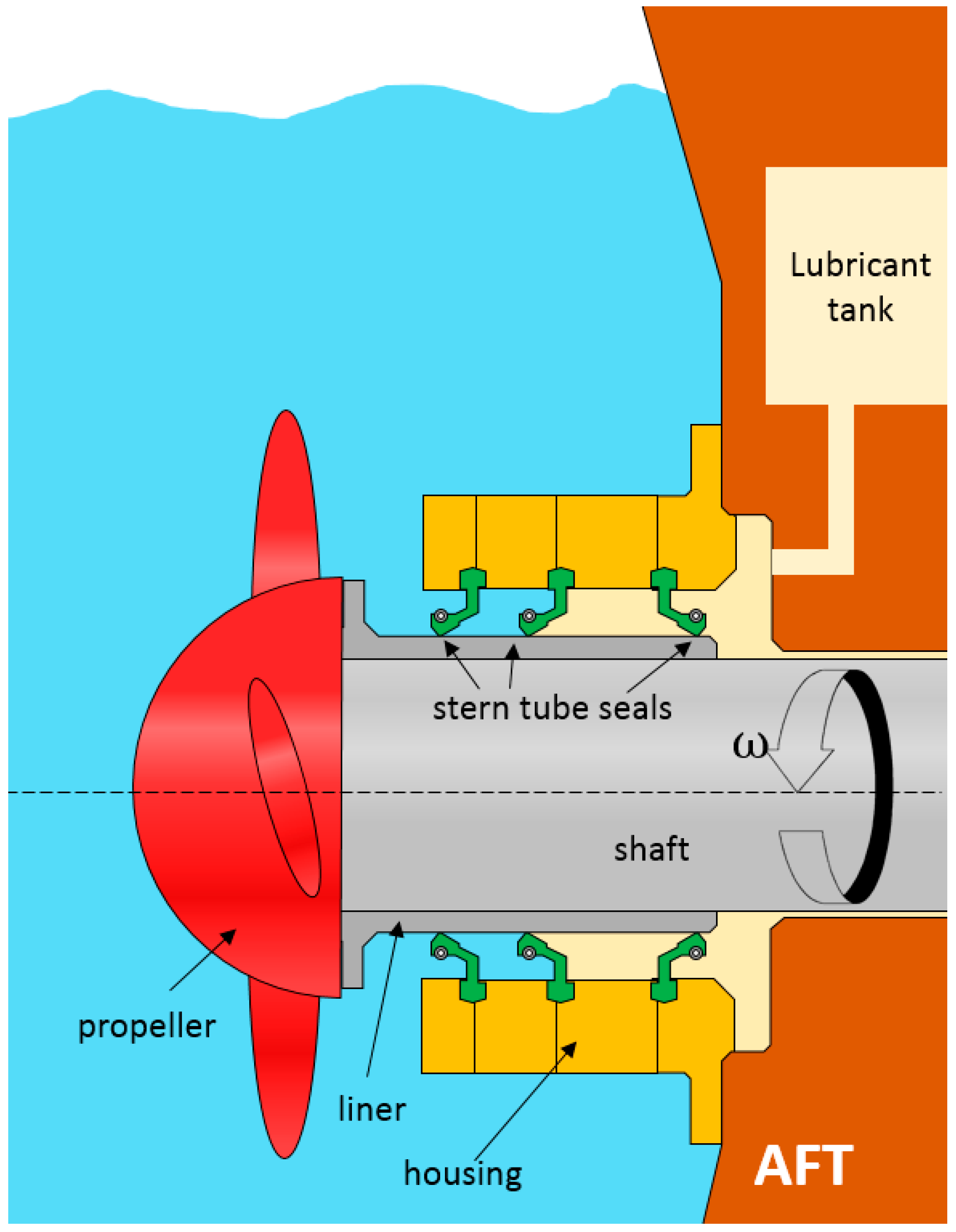
In marine applications, lubricants are required in gear boxes, thrusters, controllable pitch propellers, stabilizers, stern tube bearings and seals, rudder bearings, dredges, and grabs. These mechanical components all have an oil-to-sea interface, representing a potential source of oil spillage to the aquatic environment. Even during normal sailing, there is a continuous lubricant spillage into the sea through the stern tube seals (Figure 1) [2]. This type of rotary lip seals operates under pressurized conditions and is designed to minimize both the lubricant leakage as well as the water ingress to the stern tube.
Governmental regulations limit the use of certain lubricants in applications where there is a risk of environmental damage. The German Blue Angel, the European Eco-label, and the American Vessel General Permit (VGP) labelling programs are the most well-known. In December 2013, the use of Environmentally Acceptable Lubricants (EALs) became mandatory in large ships sailing within the coastal waters of the United States [3,4]. To minimize seawater pollution, all oil-to-sea interfaces of sailing vessels must use these more environmentally friendly lubricants. Any lubricant can be labelled as an EAL as long as it meets certain criteria: biodegradability, minimum toxicity, and bioaccumulation potential. Consequently, a wide range of lubricants tailored to fit this new legislation have been introduced to the marine lubricants segment.
The American VGP 2013 only allows the following four kinds of base oils for the formulation of EALs: hydraulic oil environmental triglyceride (HETG), hydraulic oil environmental ester synthetic (HEES), hydraulic oil environmental polyglycol (HEPG or PAG), and poly-α-olefins including related hydrocarbon products (HEPR or PAO) [4]. The first group are lubricants obtained from plants and animal fats. Although more economic than synthetic esters, their quick aging when exposed to water and heat makes them unsuitable for hydraulic systems [4]. The stricter European Eco-Label program restricts the content of a high fraction of natural esters or synthetic esters made from renewable resources in the formulation of a marine lubricant [5].
The second kind of base oils for EALs results from reacting carboxylic acids and alcohols to obtain synthetic esters (i.e., esterification reaction). These have been the obvious choice for most ship owners. These base oils can be specially tailored to the application by selecting the proper acids and alcohols to form specific esters. Synthetic esters are susceptible to hydrolysis and have compatibility problems with the elastomeric stern tube seals [4].
Petroleum-based PAG’s are obtained from ethylene or propylene oxide via polymerisation. The proportion of these dictates their solubility in water (i.e., polarity). Their maximum operation temperature is limited and they are also often incompatible with the elastomer compounds from which the stern tube seals are made [6].
Poly-α-olefin (PAO) is a synthetic compound obtained from polymerizing α-olefin. PAO is non-polar in nature, so HEES and PAG, both polar, have a higher affinity to metal surfaces. Consequently, PAOs are often mixed with esters, acting as carrier of the polar additives [7] to increase the additive solubility. There is an ongoing discussion as to whether or not PAOs are actually EALs, since they do not meet any renewable source standards and only the low viscosity types are biodegradable. In addition, they are not listed with the other three EALs in the VGP 2013 [3]. Both the base oil and additive formulation must meet the VGP legislation so the final formulation can be labelled as an EAL; consequently, the type of additives allowed is also limited [8].
Several EALs are readily available in the market, making the selection of a suitable lubricant rather complex. The current trend, as shown in the VGP 2018 draft, is that such environmental regulations become stricter with time. Nevertheless, EALs have caused controversy since they became mandatory. In addition to being more costly than mineral oil-based lubricants, it is thought that sailing with EALs causes a higher oil spillage while shortening the service life of stern tube seals. Regardless of the technical complexity of obtaining data on the stern tube of sailing vessels, running conditions differ from ship to ship, making it impossible to reliably compare the impacts of specific lubricants alone. Computational models for rotary lip seals are available in the literature; however, those models commonly assume Newtonian behavior of the lubricant [9,10]. It is unknown if the results from these models still apply when the seals operate with EALs instead, as the rheological properties are not well characterized.
For rotary lip seals, the optimal friction, leakage, and wear rate are determined during the transition from mixed to the full-film lubrication regime [11]. For a fixed gap geometry (including roughness), load W , and velocity u on a certain contact, the lubrication regime only depends on viscosity η . The viscosity of a lubricant relates the shear stress τ to the shear rate γ · . The viscosity of a fluid depends on the following: composition, temperature, shear rates, pressure, and time.
The importance of EAL composition is self-explanatory. The nature of both the base oil and the additive package play an important role in chemical incompatibility [12] with the surrounding hardware and harmful fluids (i.e., water). The possible ingress of water into the stern tube would lead to an emulsion that would affect the original properties of the lubricant. The impact of water on EALs is beyond the scope of this paper. It is difficult to break apart the formulation of a lubricant; however, the presence (or lack) of certain components can be identified using Fourier transform infrared (FT-IR) or Raman spectroscopy [13].
Lubricant formulations often use viscosity index modifiers (VII), which increase the overall viscosity of the base-lubricant blend [8]. These are usually long polymeric chains that help transmit tangential loads between the different lubricant layers. As a result of high loading, high temperature, or long running periods, the rupture of those VIIs can lead to a permanent loss of viscosity. Even if the polymeric chains show a high shear stability, they can be oriented in the direction of the flow due to shear stress, leading to a temporary loss of viscosity. In extreme situations (at higher shear rates), the lubricant takes the viscosity of its base oil or blend of base oils [7].
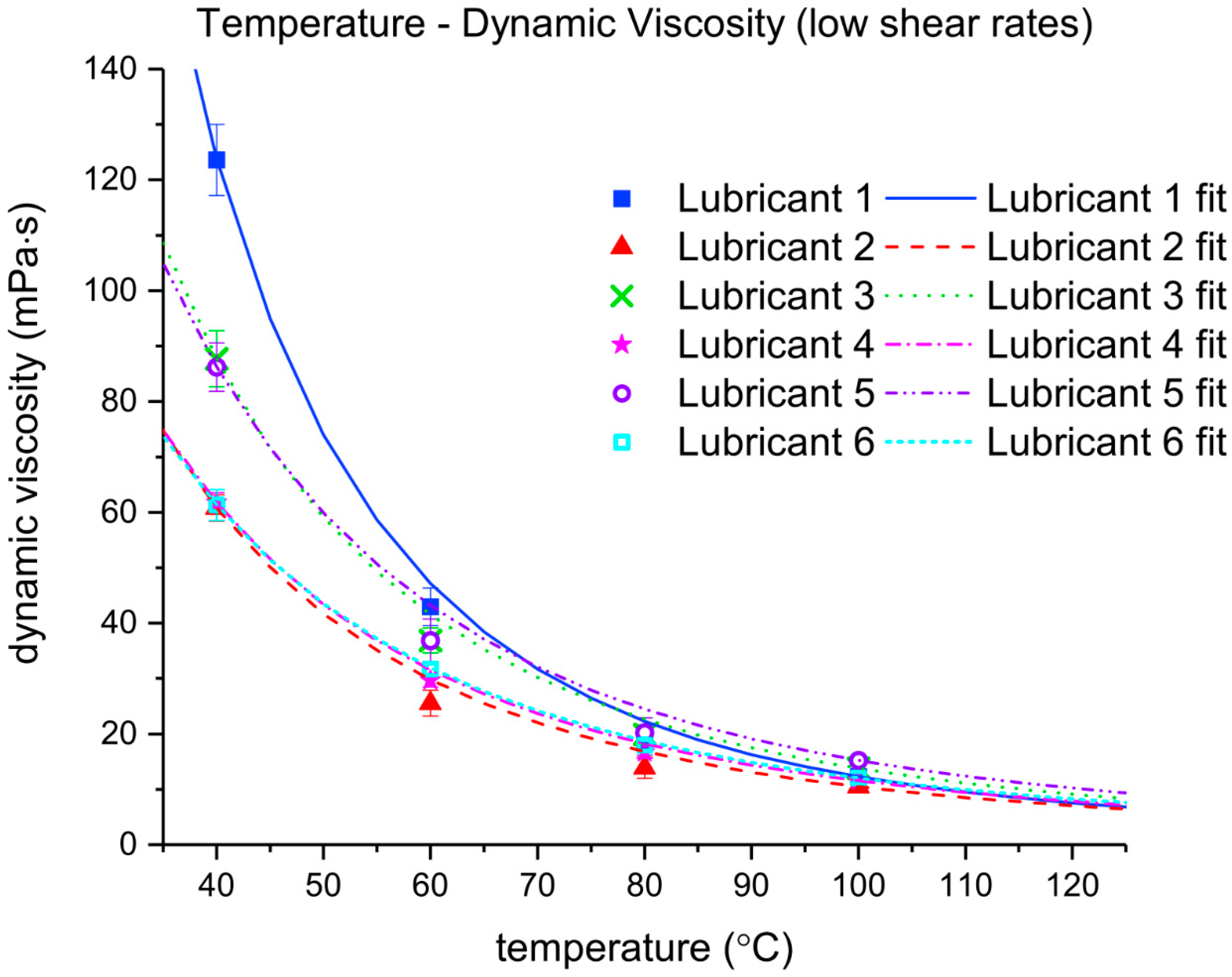
The viscosity index (VI) is a measure of the viscosity dependence on temperature T . Temperature-viscosity data are usually provided by the lubricant supplier. The shear stress of mineral oil-based lubricants is generally considered to be directly proportional to the shear rate applied to it (i.e., Newtonian behavior). However, when additives (e.g., VIIs) and contaminants increase the viscosity of the fluid at low shear rates, the lubricant can become susceptible to shear thinning. In stern tube seals, the shear rate of the lubricant is high. The ratio between the shaft liner velocity and the oil film thickness on the elastomeric seals leads to shear rates up to 106 s−1. Shear thinning can be measured via specialized rheometers that allow reaching such high shear rates. The pressure-viscosity coefficient α relates the increase in the viscosity of a lubricant with pressure. Neither the pressure on the stern tube chamber nor the hydrodynamic pressure between the stern tube seals and the liner exceed 10 MPa [14]. It can be estimated that the impact of pressure on the lubricant viscosity, even with the highest pressure-viscosity coefficients, is relatively small and can be thereby disregarded in stern tube seals.
The capability of a liquid to spread on a surface is known as wettability. Wettability cannot be disregarded in the case of stern tube seals since it determines if the fluid enters the contact zone. The affinity of the lubricant to the surrounding surfaces is a system variable and therefore it is not exclusively dependent on the fluid but also on the contacting surfaces [15]. Properties like foaming depend on viscosity and surface tension of the lubricant [7]. Both chemical incompatibilities and rheological differences with a mineral based-oil can cause EALs to perform differently.
This paper focuses on the viscosity and wettability of the lubricant, as these factors determine the properties for the lubrication and sealing performance. The viscosity of new Environmentally Acceptable Lubricants under the high shear rates found in the stern tube applications has been well characterized. In detail, a set of EALs are compared to a mineral oil-based lubricant in terms of viscosity, density, and wetting characteristics under demanding conditions. Rheological models are fitted to the measurements so these can be used in more complex lubrication models.

2. Materials and Methods

One traditional mineral oil-based marine lubricant as well as five readily available EALs were selected and are listed in Table 1. Each lubricant contains a base oil (or a blend) mixed with an additive package. Lubricant 1 is not an EAL. Lubricants 2 and 3 are synthetic esters from the same supplier as Lubricant 1. Lubricants 4 and 5 are PAOs from a second supplier and Lubricant 6 is a synthetic ester obtained from a third supplier.
The lubricants tested are used in the stern tube lubrication of big vessels. Typical operation conditions of the lubricant placed between the seals and the shaft liner (Figure 1) are shown in Table 2.
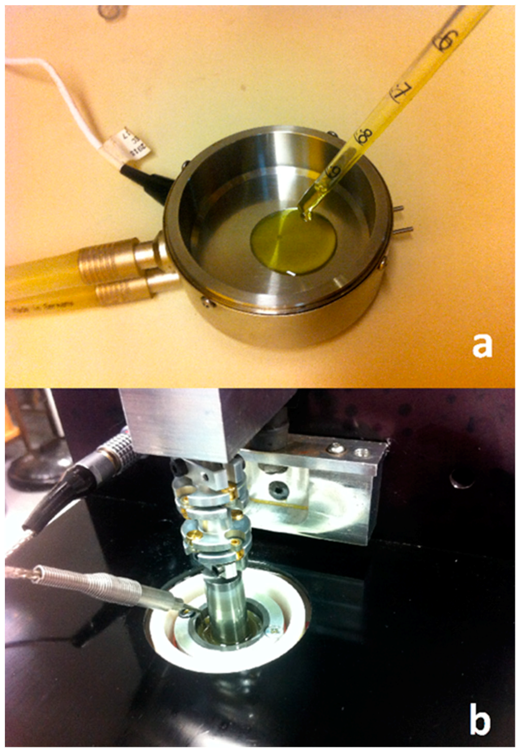
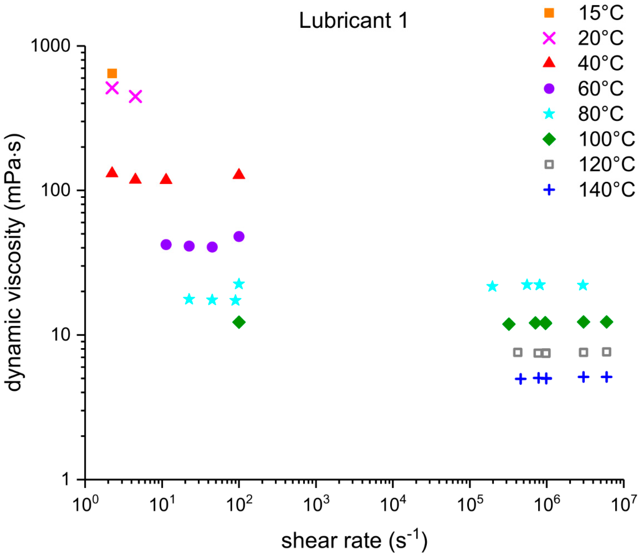
Under operational conditions, the stern tube lubricant temperature is strongly related to the sea water temperature. The ship shaft acts as a heat pipe releasing most of the heat dissipated in the stern tube bearings and seals. However, the temperature close to the running surface between the seals and liner can exceed 100 °C at the highest shaft angular speeds. A wide range of shear rates can occur depending on the operational conditions in different stern tubes. Consequently, different viscometers were used to cover a wide range of shear rates. The measurements at different temperatures and low shear rates were carried out using a low-shear rate viscometer Brookfield Pro+II (Brookfield, Middleboro, MA, USA) shown in Figure 2a. An Ultra Shear Viscometer (PCS Instruments, London, UK) was used to reach shear rates between 106 and 107 s−1 (Figure 2b). To find out if a permanent loss of viscosity developed in the lubricant, the measurement at 106 s−1 was repeated after testing a sample at the highest shear rates. The average of five measurements was calculated at each operational condition (temperature and shear rate). The high shear rate viscometer typically achieved a repeatability of 2% of the viscosity value.
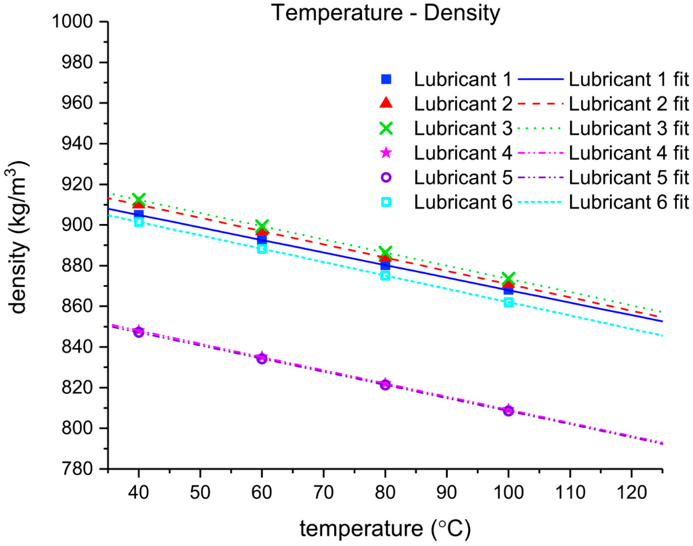
The density of each lubricant was measured using a high precision Stabinger viscometer SVM 3000 (Anton Paar, Graz, Austria), which additionally works as a densitometer. The device accurately measures the viscosity at low shear rates, so the measurements obtained with the Brookfield viscometer could be validated.
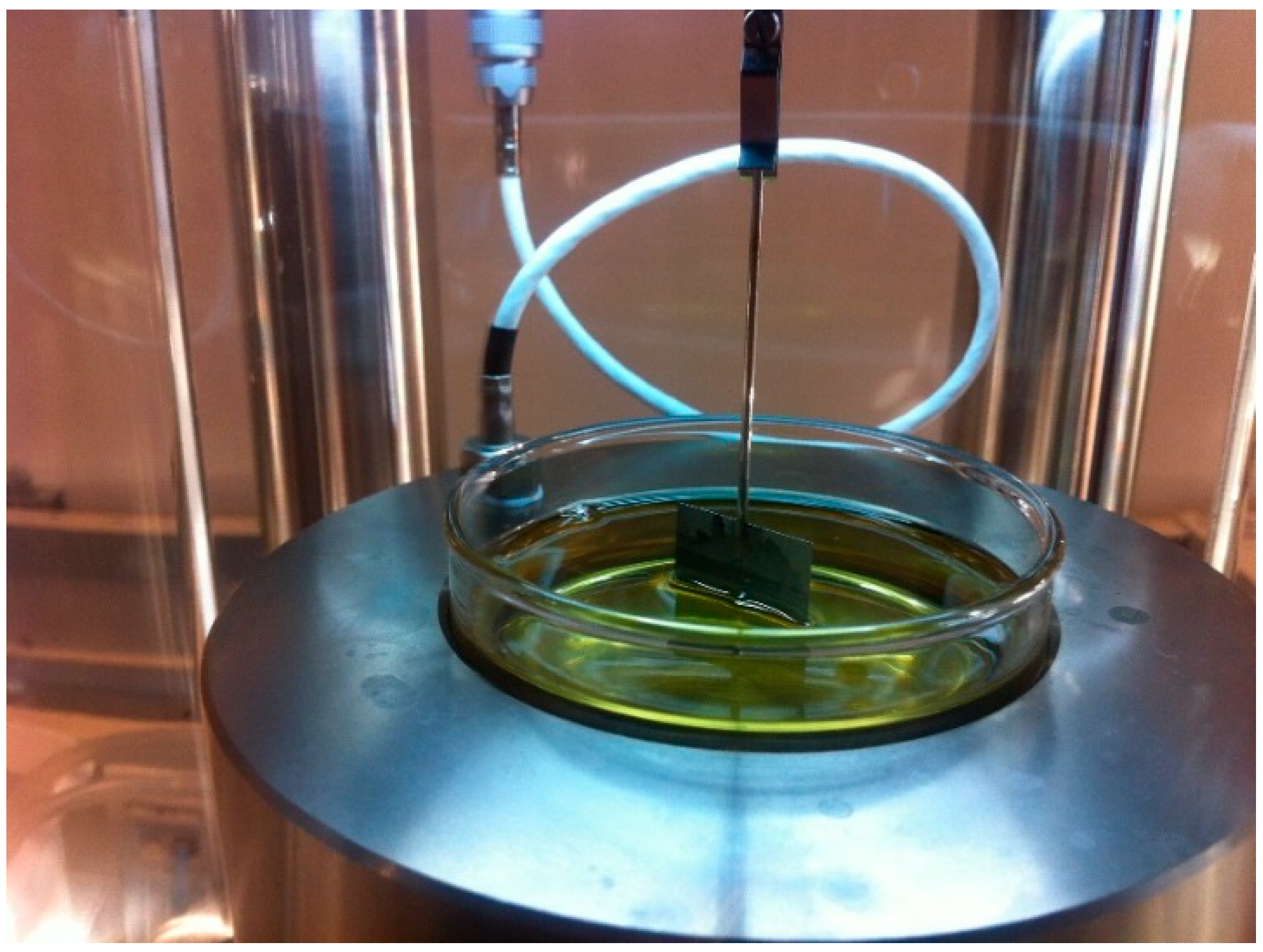
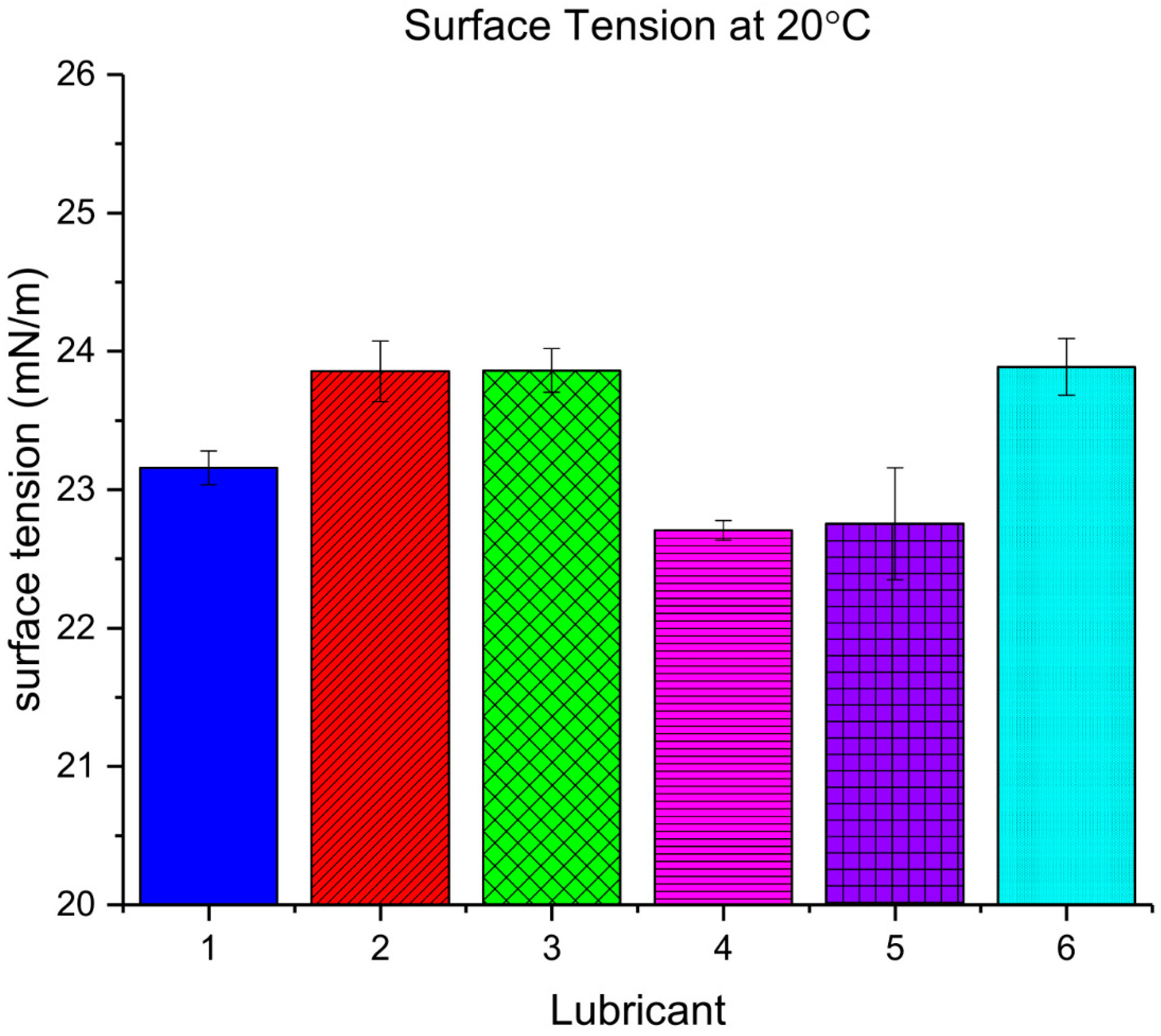
The Wilhelmy plate method on a DCAT11 tensiometer (DataPhysics, Filderstadt, Germany) was used to measure the surface tension γ L of the different lubricants (Figure 3). A platinum plate was immersed on the lubricant sample and the necessary load to pull it out was recorded. Once the plate properties and the length of the wetted perimeter of the plate L were known, it was possible to deduce the surface tension of the liquid from that pulling load F , as shown in Equation (1). The lubricants tested showed a good wettability on metal surfaces with contact angles below 10° and hence complete wetting can be assumed ( cos θ = 1 ).
F = γ L L c o s ( θ )
The test was repeated three times per lubricant and the plate was thoroughly cleaned each time with a fire gun.
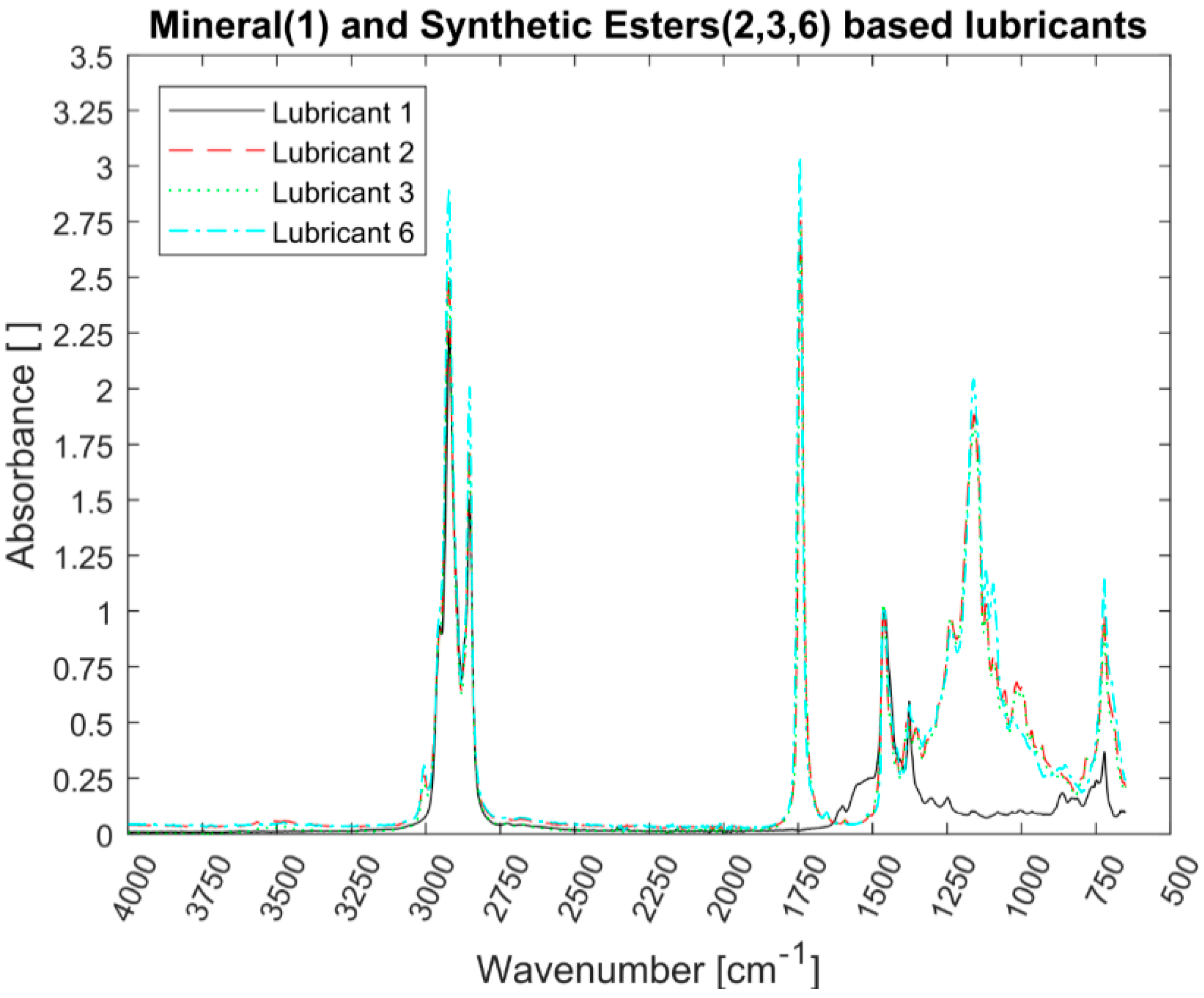
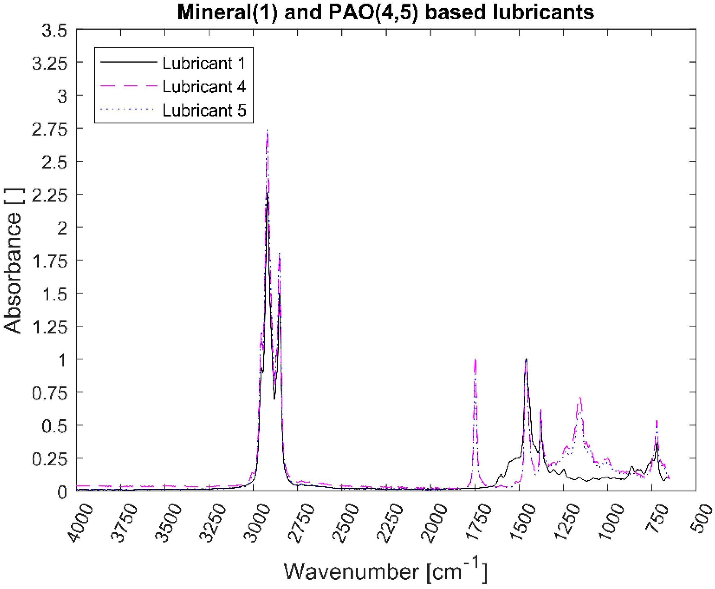
All the lubricants were analysed using a Spectrum 100 FT-IR Spectrometer (PerkinElmer, Waltham, MA, USA) with attenuated total reflection (ATR) sampling technique. Although the FT-IR technique does not reveal the specific formulation of each lubricant, the main components of the different lubricants can be identified and compared.
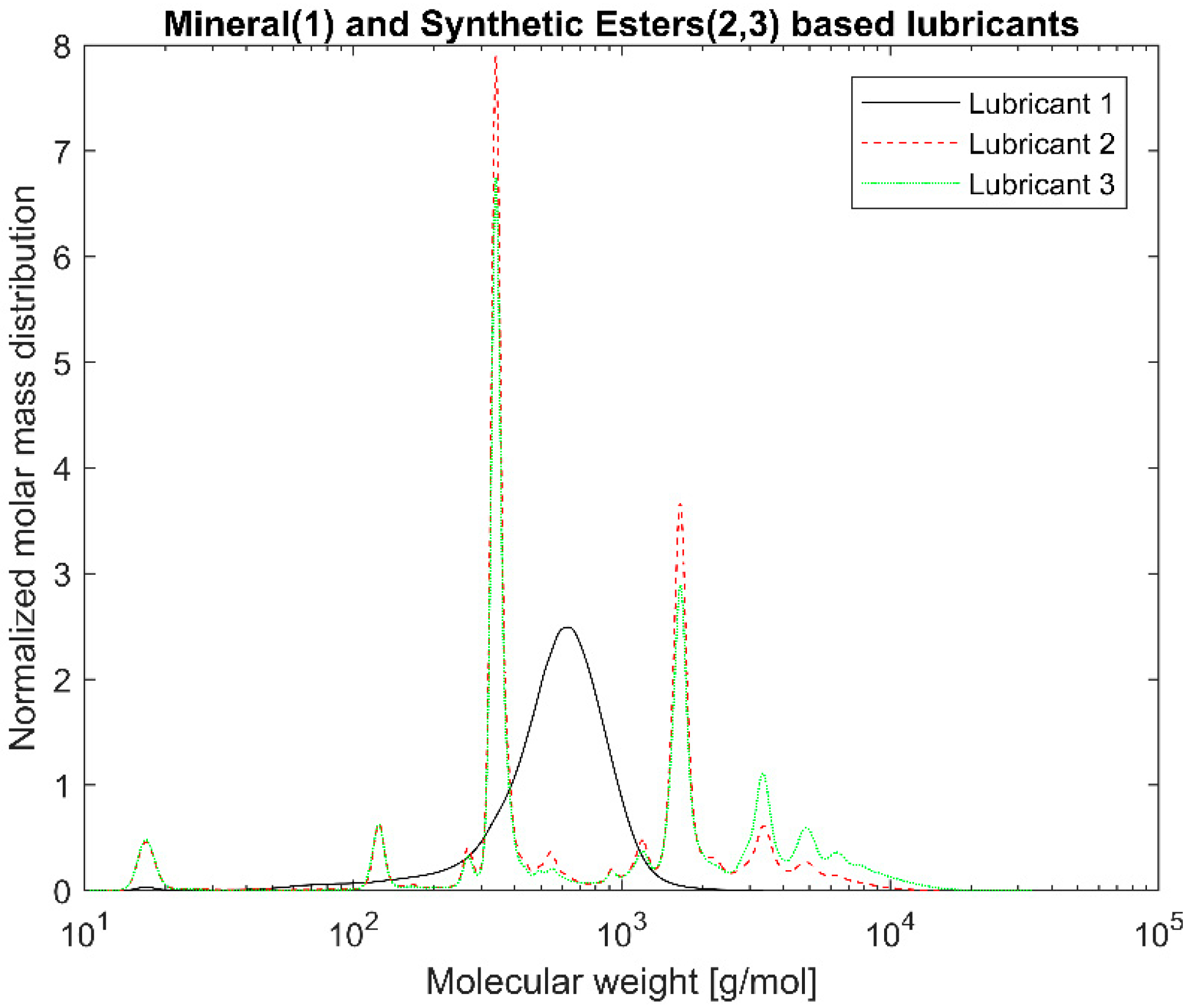
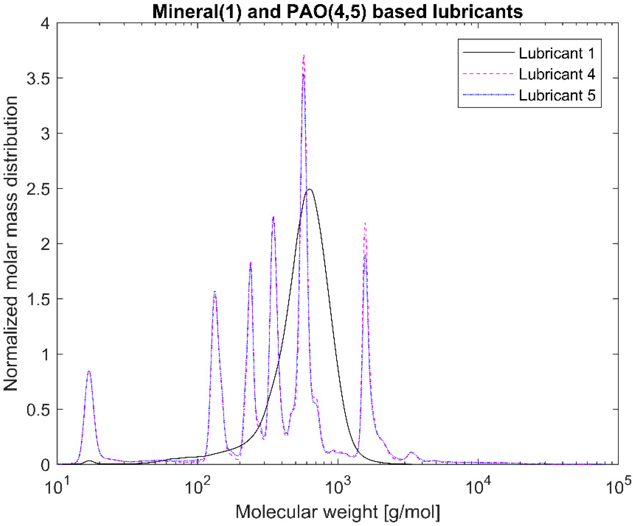
Gel Permeation Chromatography (GPC) was used to measure the molecular weight distribution of the different lubricants. The device used was an Agilent 1200 series (Agilent, Santa Clara, CA, USA) with a refractive index and an ultraviolet (UV) detector at 254 nm with three GPC PLgel 3 μm MIXED-E columns in series. The column was operated at 23 °C with tetrahydrofuran as solvent with a flowrate of 1 mL/min. Polystyrene solutions ranging from 162 to 27,810 Da were used to calibrate the device.

3. Results

3.1. Viscosity

The impact of temperature and shear rate on the viscosity of each lubricant was measured. The viscosity measurements of Lubricant 1 (Figure 4) and Lubricant 5 (Figure 5) show the impact of the shear rate for a Newtonian mineral oil and a non-Newtonian EAL, respectively. The lower shear rate measurements up to 102 s−1 were obtained with the Brookfield (Figure 2a) and Stabinger viscometers, whereas the high viscosity measurements were taken recorded the Ultra Shear Viscometer (Figure 2b).
Within the testing temperature range, there was no significant difference between EALs with a similar viscosity grade. The viscosity measurements at low shear rates of the lubricants listed in Table 1 are plotted together in Figure 6. The mineral oil-based lubricant (Lubricant 1) had the highest viscosity of 133 mPa∙s at 40 °C and a greater variation with temperature as denoted by its low VI of 95. Lubricants 2, 4, and 6 had viscosities around 68 mPa∙s at 40 °C. Lubricants 3 and 5 were the thicker EALs tested and had viscosities close to 100 mPa∙s at 40 °C. Both kinds of EALs, synthetic ester- and PAO-based, show a lower change in viscosity with temperature compared to the mineral oil-based lubricant; this was expected due to their higher VI (Table 1).
Some rheological models were fitted to the measurements obtained so these could be incorporated to more advanced computational models [16]. For Newtonian fluids, the Walther formula [17] with a shift constant Ψ = 0.7 is frequently used to relate the kinematic viscosity and temperature for liquid petroleum products [18]:
l o g ( l o g ( ν T + Ψ ) ) = A B l o g ( T )
ν T is the kinematic viscosity at a temperature T and the material constants A and B are empirical parameters obtained from fitting the function to measurements (Table 3). The Walther formula, between 40 and 100 °C, accurately captured the viscosity variation with temperature for all the lubricants. As expected from its lower viscosity index (Table 1), the viscosity of the mineral oil was more susceptible to temperature variations than the EALs tested. The dynamic and kinematic viscosities of the lubricants are related by their densities as shown in the next section.
At high shear rates, Lubricants 2 and 3 showed a shear rate-independent behavior, similar to the reference mineral oil, whereas Lubricants 4, 5, and 6 underwent a significant viscosity decrease due to shear thinning (Figure 7). We then deduced that Lubricants 4, 5, and 6 contain VIIs. The rate at which the viscosity decreases with shear rate is related to the specific VIIs used in their formulation. For Lubricant 6, the shear thinning initiated at low shear rates (102 s−1), whereas for Lubricants 4 and 5, this developed at higher shear rates (105 s−1). Contrary to the steep viscosity drop observed in Lubricants 4 and 5, the viscosity decrease of Lubricant 6 was rather slow, allowing it to carry relatively higher loads at the higher shear rates than the other two shear thinning lubricants.
Different cases of the Generalized Carreau-Yasuda law are commonly used to model the viscosity dependence on shear [19]:
η γ · = η + ( η 0 η ) [ 1 + ( γ · λ ) a ] n 1 a
where η γ · is the dynamic viscosity at shear rate γ · , η 0 is the low shear rate viscosity, η is the high shear rate viscosity, n is the power index, λ is the relaxation time (inverse of the critical shear rate γ · c ), and a is the index controlling the transition from the Newtonian plateau to power-law region.
For the results at 80 °C, the Generalized Carreau-Yasuda model was fitted and the results are shown in Figure 7. None of the lubricants tested reached the infinite viscosity plateau so this test was been considered null. As can be seen in Table 4, this model showed a high accuracy with correlation coefficient (R2) values close to unity.
There are different methods that can be used to account for both the shear rate and temperature dependencies on viscosity [7]. The simplest method is to multiply a temperature-dependent factor H ( T ) to the viscosity obtained from a non-Newtonian model F ( γ · ) :
η T , γ · = H ( T ) F ( γ · )
However, due to the shift in the shear thinning slope at different temperatures, we observed that the lubricant viscosity was not accurately captured by simply scaling the results obtained with the models previously presented. Consequently, an Arrhenius-shaped temperature-dependent term H ( T ) was included to the Generalized Carreau-Yasuda model [20,21]. The results are shown in Figure 8 and Figure 9, together with extrapolated results for temperatures between 15 and 140 °C, which is the typical range of expected operational temperatures.
η T , γ · = η T , + ( η T , 0 η T , ) [ 1 + ( γ · λ e T 0 T ) a ] n 1 a
where η T , γ · is the dynamic viscosity at temperature T and shear rate γ · , λ is the relaxation time, n is the power-law index, and T 0 is the temperature constant in Kelvin. η T , γ · is obtained by combining Equations (2) and (6). The fitting parameters for Equation (5) for the lubricants presenting shear thinning are shown in Table 5.
After the high shear rates were applied to a sample, a last final measurement point was performed to account for the potential permanent loss of viscosity due to the high shear rates to which the lubricant was exposed during testing. Notably, a certain part of the oil tested was replaced in every measurement to prevent running under starved conditions. Although the same amount of fresh lubricant was added, the amount of fresh oil entering the shearing zone could not be quantified. The average loss of viscosity per lubricant is shown in Table 6, and was small, except for Lubricant 6. This indicates a potential polymer-cracking by shear of Lubricant 6. Further specialized tests must be carried out in order to confirm this finding.

3.2. Density

The density measurement results of the lubricants at different temperatures are presented in Figure 10. The common linear relationship between temperature and density was measured for all the lubricants. We observed that PAO-based EALs have a lower density whereas the synthetic esters and the mineral oil-based lubricants had similar results (Figure 10).
Within the operating temperature range, the density varies linearly with temperature [22]. The slopes and the expected density at zero degrees for all the lubricants are shown in Table 7:
ρ T = ρ T 0 + k ( T T 0 )
where ρ T the density at temperature T , k is the slope depending on the fluid and ρ T 0 is the reference density at temperature T 0 .

3.3. Surface Tension

The surface tension γ L measurements at room temperature obtained with the Wilhelmy plate method were similar for all the liquids, as shown in Figure 11. The nature of the intermolecular forces of the lubricants could not be determined from this data; however, the overall surface tension values measured were relatively low compared to more polar liquids (e.g., water). The induced polarity from the ester groups was not significantly reflected in the overall surface tension.

3.4. Fourier-Transform Infrared Spectroscopy (FT-IR)

Figure 12 and Figure 13 show the FT-IR spectra of the synthetic esters-based and PAO-based lubricants measured together with the mineral oil-based one, respectively. The absorbance spectra were normalized to the same value of the 1460 cm−1 band. All the lubricants analysed showed the symmetric and asymmetric stretch of methylene at 2842 and 2920 cm−1 characteristic of hydrocarbons. The bands related to the ethylene and propylene segments, methylene/methyl bending and methyl bending bands, at 1464 and 1378 cm−1, respectively [23], appeared for all the lubricants tested. The C–H out of plane bending vibration and the C–H in-plane bending vibration at 726 and 1157 cm−1 were also present [13]. The latter is highly pronounced on the carbonyl group containing lubricants. The small peak at band 3005 cm−1 for all the ester-containing lubricants probably belongs to the methyl ester. The lubricants lack the absorption bands from the double carbon-to-carbon bonds at 1650 cm−1 [13]. At the highest absorption bands, nothing was displayed denoting the lack of aromatic structures, oxygen-hydrogen bonds, and consequently a lack of water content. The carbonyl group absorption bands around the 1740 and 1151 cm−1 [13] were present in both the synthetic esters and poly-α-olefin-based lubricants, whereas they were not present in the mineral oil-based one. The presence of these peaks in both Lubricants 4 and 5 suggests that the PAOs were blended with synthetic esters or the use of poly alkyl methacrylate VIIs.

3.5. Gel Permeation Chromatography (GPC)

UV detector measurements were used to plot the normalized distributions shown below. Only Lubricant 1, the mineral oil-based lubricant, showed a monodisperse broad distribution whereas the rest of synthetic lubricants showed a multimodal distribution (Figure 14 and Figure 15). The different peaks correspond to the different oils blended and the additives. Unfortunately, the polystyrene calibration charts used were not fit for the compounds measured and heavy polymeric chains might be ignored. The results presented below mainly cover the low-weight lubricant compounds.

4. Discussion

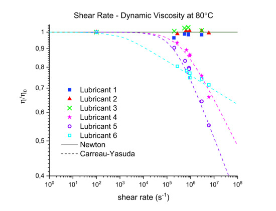
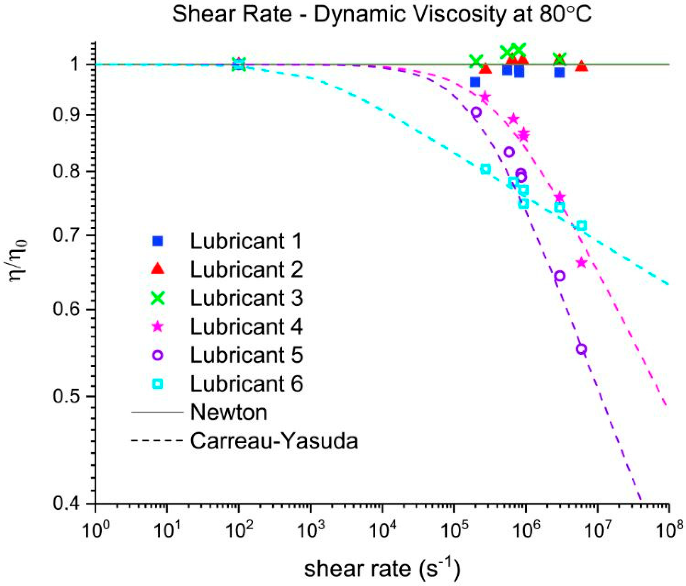
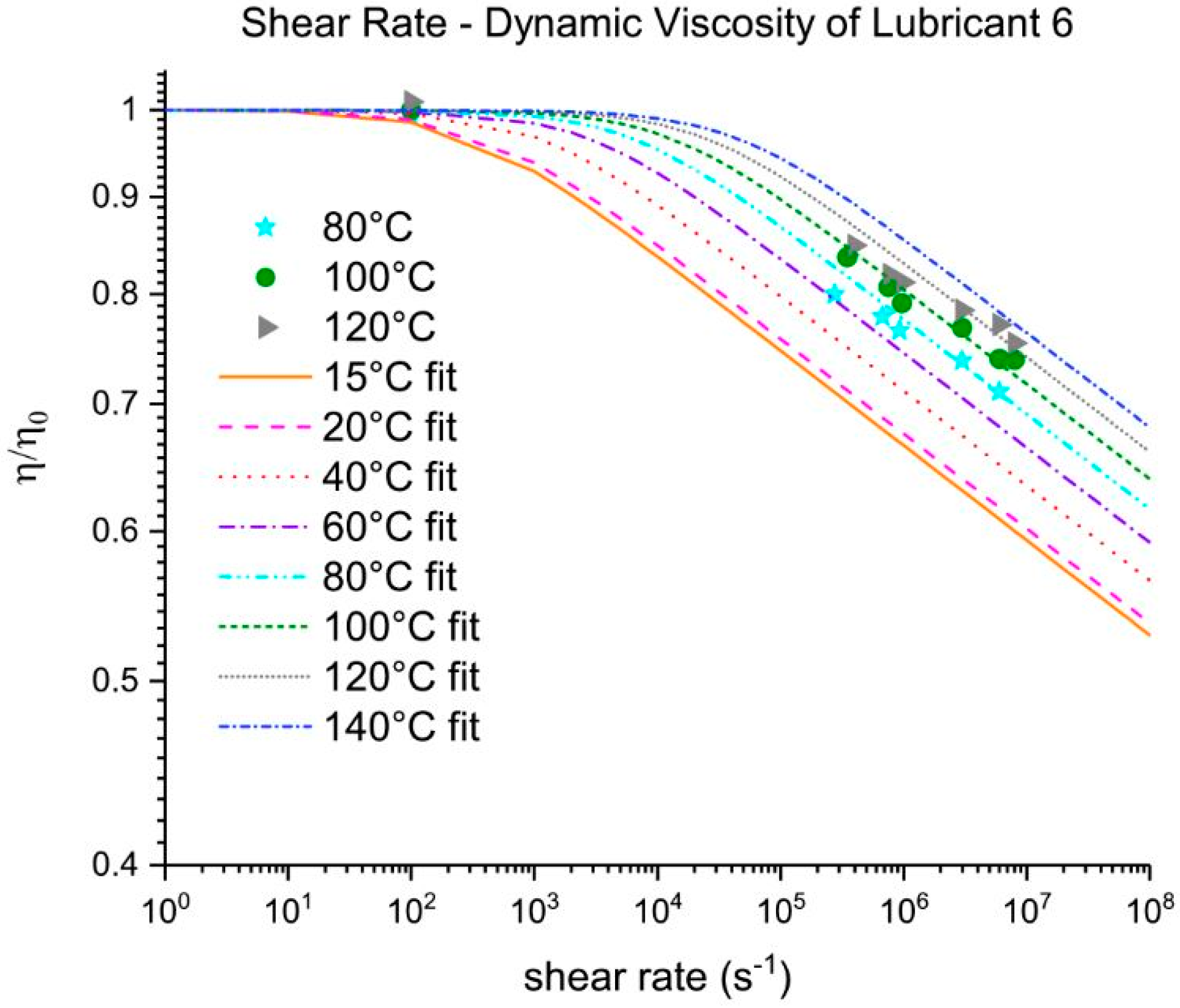
Three out of five EALs tested showed shear thinning at shear rates above 105 s−1. Shear thinning was observed in both synthetic ester as well as poly-α-olefin-based EALs. Whether or not shear thinning occurs in a stern tube depends, to a large extent, on the operational conditions in the stern tube. Assuming stern tube seals operate under their optimal point, i.e., lowest friction and wear rate values, the lubricant film thickness must be around the average roughness of the liner surface. With this educated guess, we deduced that the shear rate operational values of a ship fall within the range where shear thinning was observed.
It has been suggested that the presence of shear thinning is related to the amount and type of viscosity index improvers (VIIs) used within the lubricants formulation [24]. The IR spectra of Lubricants 2, 3, and 6 were similar; however, Lubricant 6 shear thinned at the shear rates tested whereas 2 and 3 did not. The shear thinning curves in 
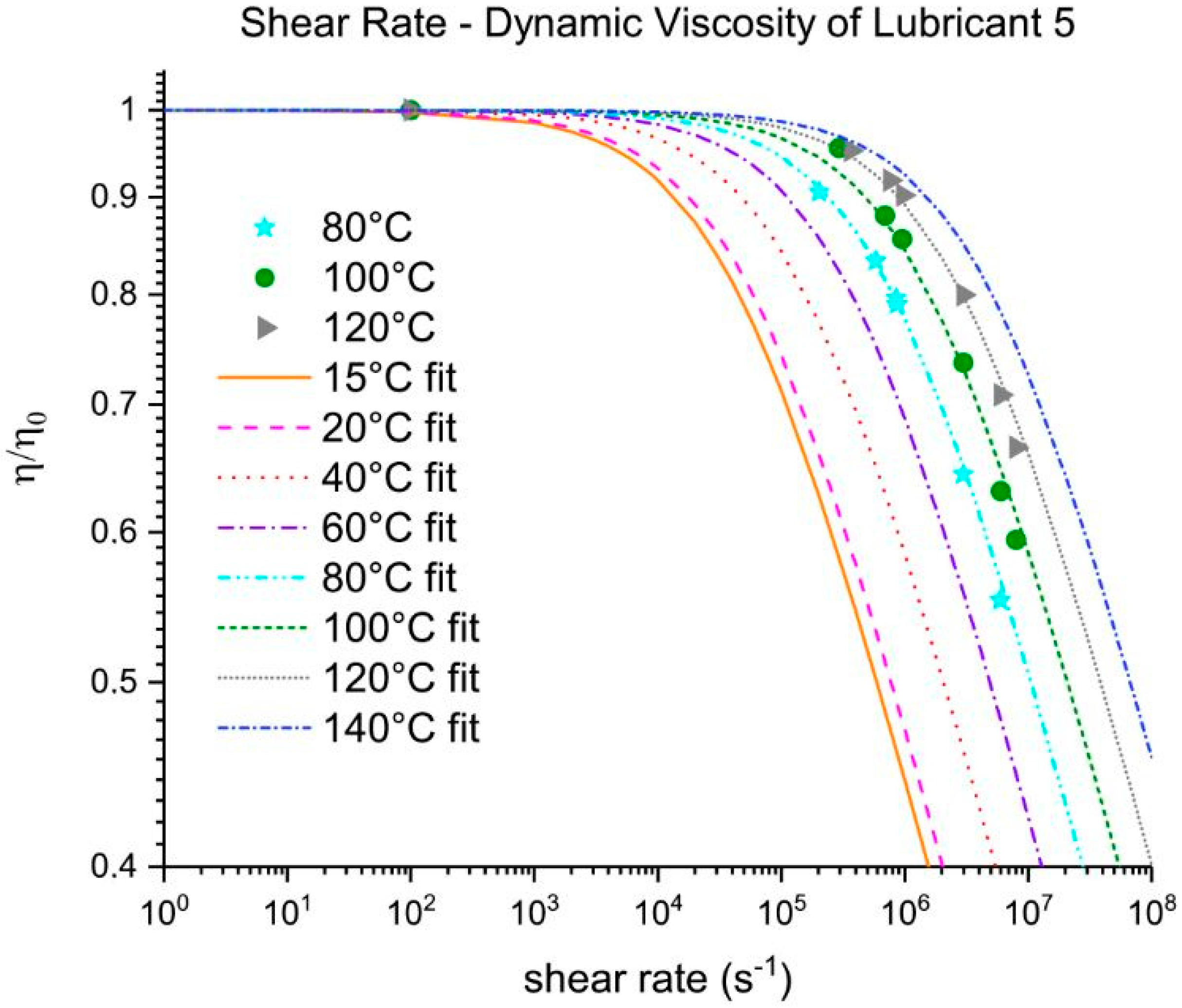
Figure 7 show a completely different shear thinning development for the ester- and PAO-based lubricants. The PAO-based lubricants (4 and 5) presented a sudden decrease in viscosity beyond a certain critical shear rate; the viscosity of lubricant 6 started at a lower shear rate and experienced a steady viscosity decrease. The shape of the polymer chains and intermolecular forces determine their ability to stretch and align themselves in the direction of flow causing a decrease in viscosity. Therefore, the different lubricant responses to shear stress shown in Figure 7 are a result of the shape, size, and interactions of the VIIs used in their formulations. A permanent loss in viscosity is attributed to the scission of the larger hydrocarbon chains of the VIIs due to mechanical loading. Lubricant 6 showed a certain polymer-cracking by shear as a result of being tested at 107 s−1 (Table 6).
The measured surface tension was shown to be within the same range for all the lubricants tested, independent of the nature of the base oil used in its formulation. The polarity of a synthetic ester is determined by the alcohols and carboxylic acids used in their formulation. Pure poly-α-olefins have a surface tension around 20 mN/m [25], which is within the range of the final PAO-based lubricants measured. The use of certain additives, like foam inhibitors, act as surface tension depressants and could mask the surface tension of the final lubricants [7]. Surface tension depressants are also commonly used to decrease the amount of swelling or shrinkage of elastomers immersed in hydrocarbon fluids [7], which is an undesirable effect in dynamic seals.
FT-IR analysis revealed that all the EALs tested contained ester-based components. Synthetic esters are frequently used in PAO-based formulations as additives carriers due to their more-polar nature [7]. Consequently, the PAO-based EALs tested can be susceptible to hydrolytic degradation due the certain amount of present esters. Lubricants 2 and 3 are synthetic esters-based from the same manufacturer. Although they have different viscosities, they displayed the same IR spectra because the functional groups are the same. The same phenomenon occurred with Lubricants 4 and 5. The GPC allowed us to distinguish the lubricants from the same manufacturer. The blend of base oils became clear for both the synthetic esters- and the PAO-based lubricants. The amount of higher molecular weight components could explain the higher viscosity of Lubricant 3 with respect to Lubricant 2. This was not as evident for the PAO-based lubricants (Lubricants 4 and 5); however, the degree of branching of different oligomers and the affinity with the solvents also plays a role in the overall viscosity. As mentioned, by polystyrene calibration standards, polymeric chains that significantly contribute to the rheology of the lubricant might unfortunately be ignored. In other words, the GPC mainly covered low molecular weight lubricant compounds. No correlation between the molecular weight distribution and the shear thinning could be established because the high molecular weight range that could confirm the presence of VIIs was neglected.
From this research, we concluded that EALs cannot directly be treated as common mineral oil-based lubricants. Although EALs perform fairly similarly with temperature as the traditional stern tube mineral oils, at high shear rates, a viscosity drop is observed for certain EALs (i.e., shear thinning). Under the same high shear running conditions, the thickness of the film between the seals and the shaft liner will be reduced when using certain EALs. By running at lower viscosities, an increase in temperature can occur if the mixed-lubrication regime is entered. Although shear thinning is not a negative characteristic per se, if the viscosity drops below a certain value, higher wear rates, temperatures, and friction loads are expected, which would consequently shorten the lifespan of the stern tube seals.
Rheological models were fitted to the measurements and accurately predicted the density, viscosity and surface tension of these lubricants for conditions as they occur in stern tube seals. Therfore, it is now possible to predict the impact of EALs in more complex mechanical models.

5. Conclusions

A set of readily available Environmentally Acceptable Lubricants (EAL) were compared under stern tube seals operational conditions. All EALs presented surface tension values between 22 and 24 mN/m. EALs and traditional mineral oil-based lubricants performed similarly within the stern tube temperature range from 20 to 100 °C. However, under shear rates of 106 s−1, a distinctive viscosity decrease up to 40% of its initial viscosity value was observed in some EALs.
The decrease was measured in both synthetic ester- and poly-α-olefin based lubricants. The steep decrease in viscosity at shear rates of 105 s−1 of Lubricants 4 and 5 was significantly different to the earlier (102 s−1) steady viscosity decrease observed in Lubricant 6. The specific type of VIIs used in the formulation of the lubricants might explain the different shear thinning developments. We concluded that the operational shear rate value of the ship, by means of fluid film thickness and shaft velocity, must be considered when selecting its stern tube lubricant.

Author Contributions

F.X.B. carried out the analysis of the lubricants and fitted the rheological models to the results obtained. M.B.d.R. arranged the use of the testing facilities and supervised the progress of the research on a weekly basis. D.J.S. reviewed the overall research.

Funding

This research received no external funding.

Acknowledgments

Nigel Marx and Marc Masen from the Imperial College of London to grant access to their facilities to carry out some of the tests. Robbie Venderbosch from the Biomass Technology Group for his guidance on organic chemistry. Ruiz Ramiro and Smink from the SPT research group for their contribution with the GPC. De Beer for her advice in polymer physics.

Conflicts of Interest

The authors declare no conflicts of interest.

References

  1. Madanhire, I.; Mbohwa, C. Mitigating Environmental Impact of Petroleum Lubricants; Springer: Berlin, Germany, 2013; pp. 1–239. [Google Scholar]
  2. Etkin, D.S. Worldwide Analysis of in-Port Vessel Operational Lubricant Discharges and Leakages; Cortlandt Manor: New York, NY, USA, 2008. [Google Scholar]
  3. United States Environmental Protection Agency. Environmentally Acceptable Lubricants; United States Environmental Protection Agency: Washington, WA, USA, 2011.
  4. Jarabo, A. Choosing optimum lubricant solutions for your operation. In Fathom Focus; Fathom: Belfast, UK, 2014. [Google Scholar]
  5. European Commission. European Union Ecolabel Application Pack for Lubricants; European Commission: Den Haag, The Netherlands, 2014. [Google Scholar]
  6. Sherman, J.V. Water soluble, environmentally acceptable lubricants for stern tube applications. In Proceedings of the Society of Naval Architects and Marine Engineers (SNAME) 14th Propeller and Shafting Symposium, Norfolk, VA, USA, 15–16 September 2015; pp. 1–10. [Google Scholar]
  7. Totten, G.; Westbrook, S.; Shah, R. Fuels and Lubricants Handbook: Technology, Properties, Performance, and Testing; ASTM International: West Conshohocken, PA, USA, 2003. [Google Scholar]
  8. Quinchia, L.A.; Delgado, M.A.; Reddyhoff, T.; Gallegos, C.; Spikes, H.A. Tribological studies of potential vegetable oil-based lubricants containing environmentally friendly viscosity modifiers. Tribiol. Int. 2014, 69, 110–117. [Google Scholar] [CrossRef]
  9. Salant, R.F.; Rocke, A.H. Hydrodynamic Analysis of the Flow in a Rotary Lip Seal Using Flow Factors. J. Tribol. 2004, 126, 156. [Google Scholar] [CrossRef]
  10. Maoui, A.; Hajjam, M.; Bonneau, D. Analysis of three-dimensional non-axisymmetric elastic effects of the lip on the thermoelastohydrodynamic radia lip seal behaviour. Proc. Inst. Mech. Eng. Part J J. Eng. Tribol. 2007, 221, 859–868. [Google Scholar] [CrossRef]
  11. Salant, R.F. Theory of lubrication of elastomeric rotary shaft seals. Proc. Inst. Mech. Eng. Part J J. Eng. Tribol. 1999, 213, 189–201. [Google Scholar] [CrossRef]
  12. Carrell, J.; Lewis, R.; Slatter, T. The Interaction of Bio-lubricants with Elastomers, Tested through Hanson Solubility Parameter and Stress Relaxation Tests. In Proceedings of the 17th Nordic Symposium on Tribology, Hämeenlinna, Finland, 14–17 June 2016; pp. 1–10. [Google Scholar]
  13. Coates, J. Interpretation of Infrared Spectra, A Practical Approach. Encycl. Anal. Chem. 2006, 1–23. [Google Scholar] [CrossRef]
  14. Flitney, R. Seals and Sealing Handbook; Elsevier: Amsterdam, The Netherlands, 2014; Volume 52. [Google Scholar]
  15. Leszek, W.; Leszek, W.J. The influence of lubricant polarity on the boundary lubrication of sliding steel contacts. Wear 1981, 73, 87–93. [Google Scholar] [CrossRef]
  16. Vingaard, M.; Endelt, B.; Christiansen, J. Implementation of a material model with shear rate and temperature dependent viscosity. In Proceedings of the 6th European LS-DYNA Users’ Conference, Gothenburg, Sweden, 29–30 May 2007; pp. 213–222. [Google Scholar]
  17. Seeton, C.J. Viscosity-temperature correlation for liquids. Tribol. Lett. 2006, 22, 67–78. [Google Scholar] [CrossRef]
  18. The American Society for Testing and Materials. Petroleum Products and Lubricants (I). In Annual Book of ASTM Standards; No. Part 23; The American Society for Testing and Materials: West Conshohocken, PA, USA, 1981. [Google Scholar]
  19. Kennedy, P.; Zheng, R. Flow Analysis of Injection Molds, 2nd ed.; Carl Hanser Verlag: Munich, Germany, 2013. [Google Scholar]
  20. Eckert, E.R.G.; Shadid, J.N. Viscous heating of a cylinder with finite length by a high viscosity fluid in steady longitudinal flow -II. Non-Newtonian Carreau model fluids. Int. J. Heat Mass Transf. 1992, 35, 2739–2749. [Google Scholar]
  21. Viscosity for Non-Newtonian Fluids. In Fluent 6.1. User’s Guide; Fluent Inc.: New York, NY, USA, 2003; pp. 7–24.
  22. Wong, P.L.; Wang, R.; Lingard, S. Pressure and temperature dependence of the density of liquid lubricants. Wear 1996, 201, 58–63. [Google Scholar] [CrossRef]
  23. Torres, E. Molecularly Designed Viscosity Index Improvers for Lubricants. Ph.D. Thesis, University of South Australia, Adelaide, Australia, 2003. [Google Scholar]
  24. Zolper, T.J.; He, Y.; Delferro, M.; Shiller, P.; Doll, G.; Lotfizadeh Dehkordi, B.; Ren, N.; Lockwood, F.; Marks, T.J.; Chung, Y.W.; et al. Investigation of Shear-Thinning Behavior on Film Thickness and Friction Coefficient of Polyalphaolefin Base Fluids with Varying Olefin Copolymer Content. J. Tribol. 2016, 139, 2. [Google Scholar] [CrossRef]
  25. Fiedler, M.; Sánchez, R.; Valencia, C.; Leopold, C.; Kuhn, E.; Franco, J. Influence of Base Oil Polarity on the Transient Shear Flow of Biodegradable Lubricating Greases. Lubricants 2015, 3, 611–627. [Google Scholar] [CrossRef] [Green Version]
Figure 1. Traditional stern tube arrangement in a marine vessel.
Lubricants 06 00100 g001
Figure 2. Measurement of the viscosity at (a) low shear rates and (b) high shear rates.
Lubricants 06 00100 g002
Figure 3. Measurement of surface tension using the Wilhelmy plate method.
Lubricants 06 00100 g003
Figure 4. Viscosity measurements at different temperatures and shear rates for the reference mineral-based oil (Lubricant 1).
Lubricants 06 00100 g004
Figure 5. Viscosity measurements at different temperatures and shear rates for a PAO-based lubricant (Lubricant 5).
Lubricants 06 00100 g005
Figure 6. Comparison of the low shear rates viscosity at different temperatures for lubricants based on mineral oil (Lubricant 1), synthetic esters (Lubricants 2, 3, and 6) and poly-α-olefins (Lubricants 4 and 5) listed in Table 1. Results obtained with Brookfield and Stabinger viscometers.
Lubricants 06 00100 g006
Figure 7. Normalized viscosity measurements at 80 °C and fitting of the Generalized Carreau-Yasuda model.
Lubricants 06 00100 g007
Figure 8. Normalized viscosity of Lubricant 5 as a function of the shear rate and temperature-dependent Generalized Carreau-Yasuda fit.
Lubricants 06 00100 g008
Figure 9. Normalized viscosity of Lubricant 6 as a function of the shear rate and temperature-dependent Generalized Carreau-Yasuda fit.
Lubricants 06 00100 g009
Figure 10. Comparison of the density at different temperatures.
Lubricants 06 00100 g010
Figure 11. Comparison of surface tension of the lubricants at room temperature.
Lubricants 06 00100 g011
Figure 12. Comparison of infrared (IR) spectra of synthetic esters-based lubricants (Lubricants 2, 3, and 6) and a mineral based-oil one (Lubricant 1). The spectra is normalized to the value of the 1460 cm−1 band.
Lubricants 06 00100 g012
Figure 13. Comparison of IR spectra of PAO-based lubricants (Lubricants 4 and 5) and a mineral based-oil one (Lubricant 1). The spectra is normalized to the value of the 1460 cm−1 band.
Lubricants 06 00100 g013
Figure 14. Comparison of the normalized molar mass distribution of synthetic esters-based lubricants (Lubricants 2 and 3) and a mineral based-oil one (Lubricant 1).
Lubricants 06 00100 g014
Figure 15. Comparison of normalized molar mass distribution of PAO-based lubricants (Lubricants 4 and 5) and a mineral based-oil one (Lubricant 1).
Lubricants 06 00100 g015
Table 1. Set of lubricants tested.
Lubricant Base OilViscosity @ 40 °C (mm2/s)Viscosity @ 100 °C (mm2/s)VI
Lubricant 1Supplier Ano EALMineral13313.595
Lubricant 2Supplier AEALSynthetic Ester7013.3195
Lubricant 3Supplier AEALSynthetic Ester10316.9178
Lubricant 4Supplier BEALPAO6813.5205
Lubricant 5Supplier BEALPAO10020.0225
Lubricant 6Supplier CEALSynthetic Ester6814.0215
Table 2. Stern tube seals running conditions.
LubricantMinimumMaximum
Temperature20 °C100 °C
Shear Rate0 s−1107 s−1
PressurePcav 110 MPa
1 Cavitation pressure of the lubricant.
Table 3. Fitting parameters according to Walther formula (Figure 6).
ABR2
Lubricant 18.8983.4330.98
Lubricant 27.4472.8790.98
Lubricant 37.2702.7940.97
Lubricant 46.8582.6390.99
Lubricant 56.6082.5260.96
Lubricant 66.7452.5970.99
Table 4. Fitting parameters Generalized Carreau-Yasuda model at 80 °C for the lubricants showing shear-thinning. The results are depicted in Figure 7.
η 0 η a n γ · c   =   λ 1 R 2
Lubricant 418.0600.900.873.84 × 1050.97
Lubricant 524.2101.060.831.92 × 1050.98
Lubricant 618.5401.000.960.10 × 1040.99
Table 5. Fitting parameters of the temperature-dependent Generalized Carreau-Yasuda model for the lubricants showing shear-thinning.
Lubricant η T , 0 η T , a n γ · c   =   λ 1 T 0 R 2
4 η T , 0 00.90.702.9 × 101142000.96
5 η T , 0 00.80.752.6 × 101145000.98
6 η T , 0 01.00.955.0 × 10948000.92
Table 6. Permanent viscosity loss of the lubricants at 106 s−1 and 80 °C after being tested at the higher shear rates.
LubricantViscosity Change
1−0.73%
2−0.01%
30.01%
4−0.79%
5−0.81%
6−2.81%
Table 7. Coefficients from linear fitting density and temperature.
Lubricant k ρ T 0 = 0 °C R 2
1−0.616929.560.99
2−0.652936.090.99
3−0.649938.370.99
4−0.649874.020.99
5−0.645872.950.99
6−0.657927.740.99

