


Abstract
As the rotational speed increases, the centrifugal expansion of the rotor will significantly affect the performance of the porous gas bearing. However, this rotor’s centrifugal effect has not been studied thoroughly. In this paper, the rotor centrifugal expansion is simplified as a two-dimensional plane stress problem. The gas flow in the porous bushing and the gas film is governed by Darcy’s law and the modified Reynolds equation, respectively. The perturbation method and the finite difference method are adopted to calculate the bearing load and dynamic coefficients for a high-speed porous gas bearing. Comparisons between the simulated results and the available experimental and theoretical data are carried out to validate the proposed model. On this basis, the influence of rotor centrifugal expansion on the performance and the operational conditions of the high-speed porous gas bearing is studied systematically. The results indicate that rotor centrifugal expansion greatly improves the bearing load and dynamic coefficients of the high-speed porous gas bearing with a large rotor diameter and small bearing clearance, but reduces the allowable eccentricity ratio and titling angle.
1. Introduction
Porous gas bearings have been widely applied in various types of rotating machinery. Compared to gas bearings with orifice restrictors, porous gas bearings offer higher load capacity, smoother rotation, lower risk of restrictor holes being blocked, and lower manufacturing costs [1,2,3]. Nowadays, the limited speed of the porous-gas-bearing-supported air spindle is urgently sought to be increased to further increase the productivity or machining precision. In the printed circuit board (PCB) drilling air spindle, the maximum rotational speed of the air bearing in the motorized spindle can reach a level of 400,000 r/min [4]. With the rotational speed increasing, the centrifugal expansion of the rotor can reach a level of microns, which can not be ignored, considering that the bearing gap of the porous gas bearing typically ranges from 5 to 20 μm [5,6,7]. As a result, the bearing’s characteristics can change significantly. The effect of the rotor’s centrifugal expansion in the bearing bore should receive enough attention in studying the characteristics of high-speed porous gas bearings.
Considerable studies on the supporting characteristics of the porous gas bearing have been conducted. In early investigations [8,9,10], the rotational speed was low, so rotor rotation was neglected, and the centrifugal expansion of the rotor was assumed to be zero. As rotational speed increases, the high-speed effect plays a more important role in the performance of the porous gas bearing [11,12,13,14]. Taking rotational speed into account, the effects of various parameters, including supply pressure, bearing length, bore diameter, rotational speed, and eccentricity ratio, on bearing load and dynamic coefficients have been discussed [15,16,17,18,19,20]. However, the high-speed effects introduced in the above studies include only the dynamic effect, turbulence effect, and thermal effect of the gas flow in the bearing clearance. In other words, previous works on porous gas bearings focus on the lubricant, while the rotor is simplified as a rigid body, and the centrifugal expansion of the rotor was always overlooked. In principle, the rotor’s centrifugal expansion in the bearing bush caused by high-speed rotation inevitably reduces the gas film thickness in the bearing clearance. This not only changes the static and dynamic characteristics of the gas film but also reduces the allowable angular misalignment of the bearings.
Therefore, in this paper, a lubrication model for a high-speed porous gas bearing that accounts for the rotor’s centrifugal effect is established based on the theory of elasticity, Darcy’s law, and the modified Reynolds equation. In addition, the tilting effect of the rotor in the porous bush is included in the model, yielding a 4-degree-of-freedom (DOF) dynamic model for a high-speed porous gas bearing. The static and dynamic equations for the high-speed porous gas bearing are derived using the perturbation method, and the bearing load and dynamic coefficients are then calculated using the finite difference method. Finally, the bearing load and dynamic coefficients of the high-speed porous gas bearing are discussed for different rotational speeds, bearing clearances, rotor diameters, eccentricity ratios, and tilting angles.
2. Theoretical Model
2.1. Physical Description of High-Speed Porous Gas Bearing
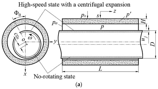
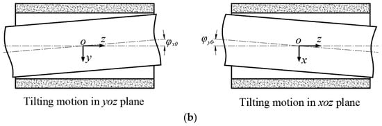
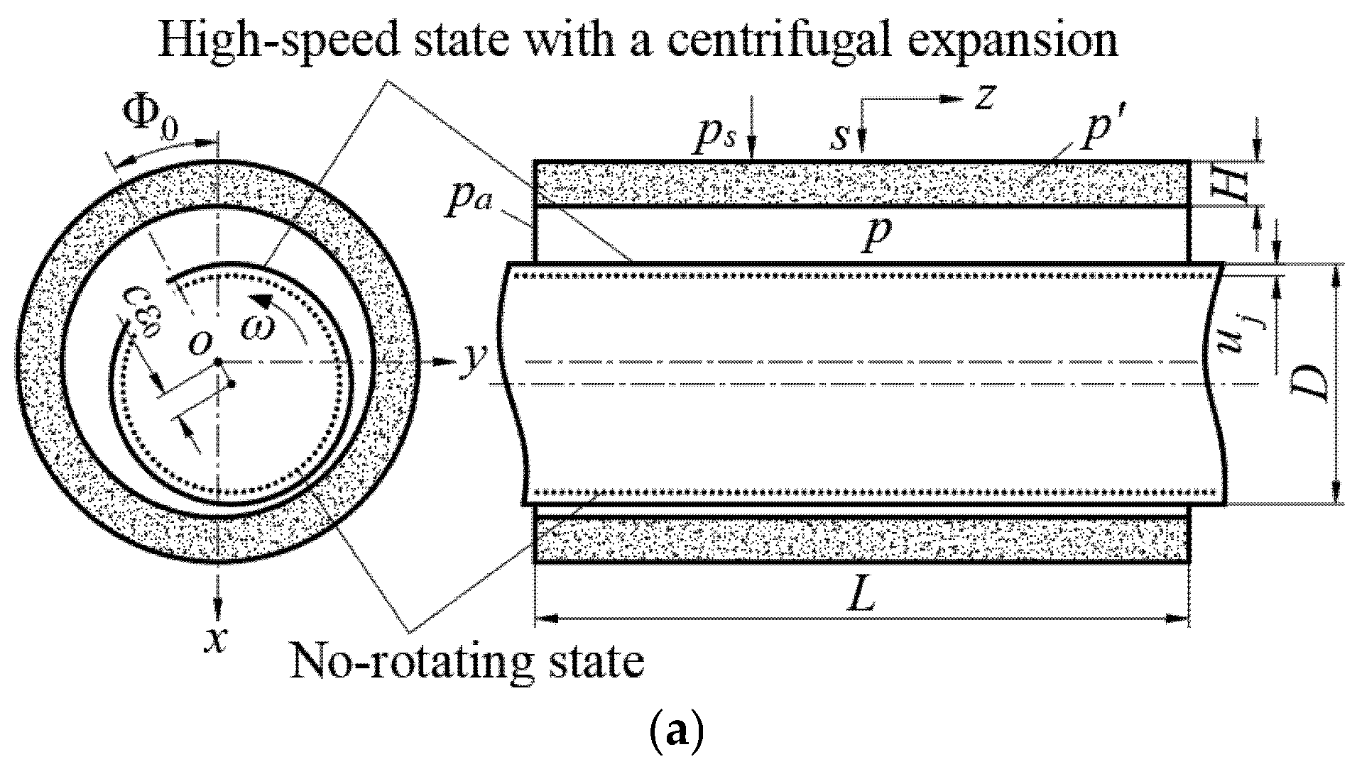
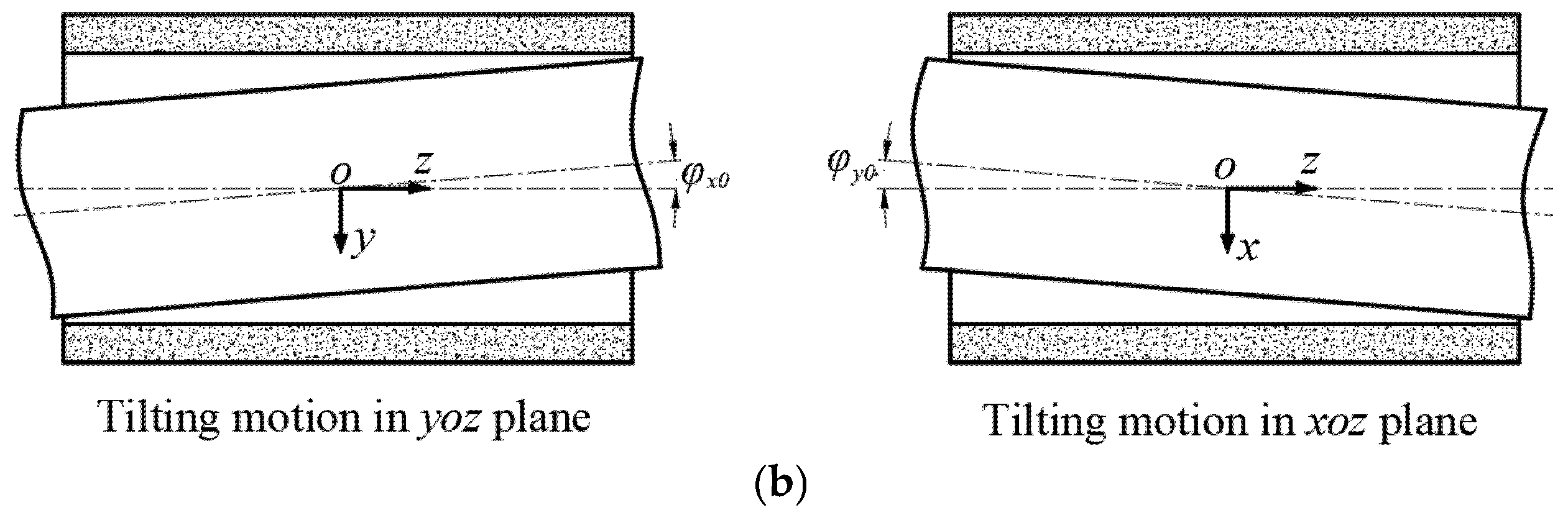
Figure 1 illustrates the physical description of the high-speed porous gas bearing. Figure 1a displays the geometrical structure and physical parameters of the bearing operating with an eccentricity ratio . Specifically, due to the ultra-high rotating speed (>50,000 r/min), the rotor may undergo a non-negligible centrifugal expansion . Meanwhile, due to external loads, the rotor may tilt in the bearing bush by an angle in the yoz plane and an angle in the xoz plane, as shown in Figure 1b. The inclusion of the rotor’s tilting motion yields a 4-DOF dynamic model of the high-speed porous gas bearing.
Figure 1.
(a) Schematic view of the high-speed porous gas bearing with the rotor centrifugal expansion; (b) tilting motion of the rotor in xoz and yoz planes.
2.2. Assumptions
The following assumptions are made for modeling purposes:
- (1)
- The centrifugal expansion of the rotor is an elastic deformation;
- (2)
- The rotor deformation due to gas pressure is ignored;
- (3)
- The high-speed porous gas bearing is in full lubrication;
- (4)
- The lubricant is an isothermal Newtonian fluid;
- (5)
- Only the gas flow along the radial direction in the bush is considered;
- (6)
- The permeability of the high-speed porous gas bearing is uniform;
- (7)
- The surface roughness of the porous gas bearing is ignored;
- (8)
- The velocity slip along the tangential direction of the high-speed porous gas bearing is negligible.
2.3. Centrifugal Expansion of the Rotor
Based on the theory of elasticity, the rotor is assumed to be an elastic cylinder, and the calculation of its radial deformation is simplified as a two-dimensional plane-stress problem. The equilibrium equation for the rotor, including the centrifugal force, is as follows [21,22]:
The geometric equations and stress–strain equations for the rotor are as follows:
By substituting Equations (2) and (3) into Equation (1), one can obtain the following differential equation:
By integrating Equation (4) twice, the radial deformation of the rotor can be expressed as
where and can be calculated using the following boundary conditions:
The pressure in the gas film can be assumed to be zero due to the fact that the gas pressure has little impact on the deformation of the rotor. Then, the auxiliary variables of and are solved to be
The centrifugal expansion of the rotor can be written as a function of the angular velocity:
2.4. Governing Equations of High-Speed Porous Gas Bearing
2.4.1. Transient Equations
The flow through the porous bushing obeys Darcy’s law, and the gas flow in the bearing clearance can be governed by the modified Reynolds equation. The non-dimensional transient governing equations for the pressure in the porous bushing and bearing clearance are given as follows, respectively [9,14,23,24,25,26]:
2.4.2. Static and Perturbed Equations
To calculate the static and dynamic characteristics of the high-speed porous gas bearing, the linear perturbation analysis is performed for Equations (9) and (10). As a result, the gas film thickness, including the rotor centrifugal expansion , can be expanded by only keeping 0- and 1-order items and is expressed as [27]
where is the static film thickness, and are the static eccentricity and the attitude angle, respectively, and , , , , , and denote the perturbed displacements.
According to the perturbation method, and are expressed as the 0th and the 1st-order Taylor expansions. Then, substituting them into Equations (9) and (10), and neglecting the higher-order terms of , the static and perturbed equations of the high-speed porous gas bearing are derived.
In the porous bushing, the static and perturbed equations are given as
where , , , , .
In the bearing clearance, the static and perturbed equations are given as
The boundary conditions for the bearing are
Substituting Equations (17) and (18) into Equations (12)–(14), one can obtain:
Then Equations (15) and (16) can be simplified as
2.5. Static and Dynamic Characteristics
The finite difference method is used to calculate the static pressure and the perturbation pressures and (). The bearing load, stiffness, and damping coefficients of the high-speed porous gas bearing can be obtained by integrating the static pressure and the perturbation pressure within the whole bearing:
2.6. Computation Flowchart
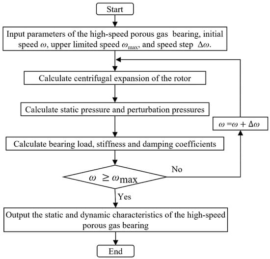
Figure 2 shows the computation flowchart for the load-carrying capability of the high-speed porous gas bearing, including the rotor centrifugal effect. The calculating procedure is as follows: (1) input parameters of the high-speed porous gas bearing; (2) calculate the centrifugal expansion of the rotor using Equation (8); (3) solve the static and dynamic equations to calculate the static pressure and perturbation pressures of the high-speed porous gas bearing using the finite difference method; (4) calculate the bearing load, stiffness and damping coefficients of the high-speed porous gas bearing using Equations (24)–(26); (5) repeat steps (2)–(4) at each rotational speed; and (6) output the load-carrying capability of the high-speed porous gas bearing.
Figure 2.
Computation flowchart for high-speed porous gas bearing.
3. Model Validation
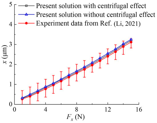
To validate the theoretical model established in Section 2 for the high-speed porous gas bearing considering rotor centrifugal expansion, the simulated results are compared with reported experimental data and theoretical solutions. In the experimental literature, most published papers have focused on the performance of porous gas journal bearings in a non-rotating state. Recently, Li et al. [24] conducted an experimental study on the characteristics of porous gas journal bearings under high-speed rotating state (24,000 r/min). The parameters of the bearing tested in their study are listed in Table 1. Li utilized a static loading method to measure the load capacity of the bearing in terms of the load–deflection curve. Figure 3 provides a comparison of the theoretical solution from the established model and Li’s experimental data for the bearing static load–deflection relationship. It can be seen from the figure that the theoretical predictions agree well with the experimental results. However, it should be noted that, at a rotational speed of 24,000 rpm, the centrifugal effect of the rotor has only a minor influence on the static load-carrying capacity of the bearing. This is because, for gas bearings, 24,000 rpm (corresponding to a DN value of ) is a relatively low operating speed at which the rotor centrifugal effect is not pronounced.
Table 1.
Parameters of the tested porous gas bearing.
Figure 3.
Comparison between the simulated results of the experiment data from Ref. [24] for the bearing load–deflection curve.
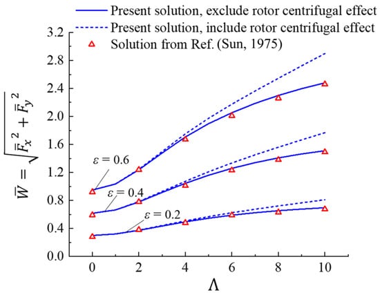
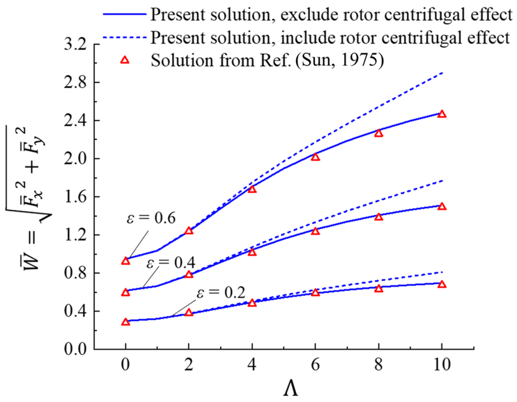
To further validate the accuracy of the developed model under high-speed operating conditions, the present solutions are compared with the simulated results reported in Ref. [28]. Given the large bearing number Λ (high rotary speed) involved in Ref. [28], both of the dimensionless load capacities calculated by the present method, including and excluding the rotor centrifugal effect, are calculated and given in Figure 4. It is evident that, when excluding the rotor centrifugal effect as considered in the model of Ref. [28], the present solution agrees well with the results in Ref. [28], demonstrating the effectiveness of the proposed model. In addition, the difference between the results with and without considering the rotor centrifugal effect becomes more significant as the rotary speed increases (Λ = 10 corresponds to a rotary speed of 200,000 r/min), and this difference increases with the eccentricity ratio.
Figure 4.
Comparison between the simulated results of this study and Ref. [28].
To date, the governing equation for the porous gas bearing has predominantly been solved using the finite difference method (FDM) [24,27,29,30,31]. To validate the accuracy of the computational algorithm developed in this study based on FDM, the present solution is compared with Rohde’s results [32] obtained using the finite element method (FEM). The detailed comparison is listed in Table 2. Our results agree well with Rohde’s.
Table 2.
Comparison of solutions by FDM and by FEM by Rohde [32] (feeding parameter , lenth to diameter L/D = 1).
4. Result and Discussion
To better reveal how rotor centrifugal expansion affects the characteristics and operation of the high-speed porous gas bearing, this section presents a comparative analysis of simulated results with and without rotor centrifugal effects. Four critical parameters, namely rotational speed n, rotor diameter D, eccentricity ratio ε, and tilting angle θy, are investigated in the analysis. The details of the four parameters are listed in Table 3. The values of the other parameters involved in the calculation are detailed in Table 1. It is noted that the other parameters are held constant when studying the influence of a single parameter.
Table 3.
Values of the parameter used in the theory calculation.
4.1. Influences of Centrifugal Expansion on Bearing’s Characteristics
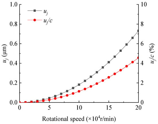
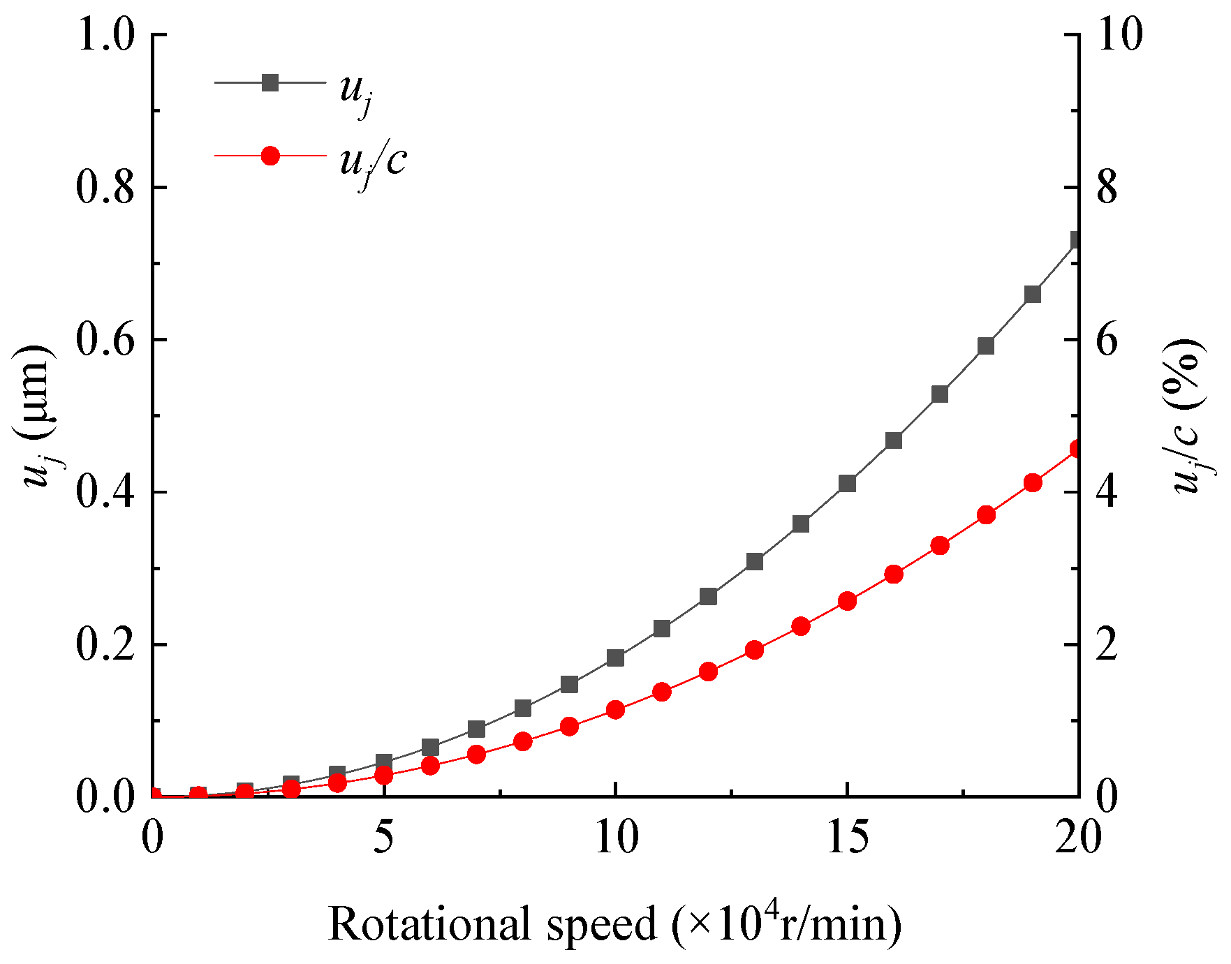
As a result, the rotor’s centrifugal expansion is directly determined by the rotational speed and the rotor diameter; these two parameters are treated as variables in the analysis.
4.1.1. Rotational Speed
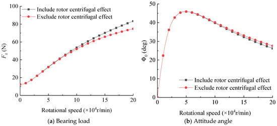
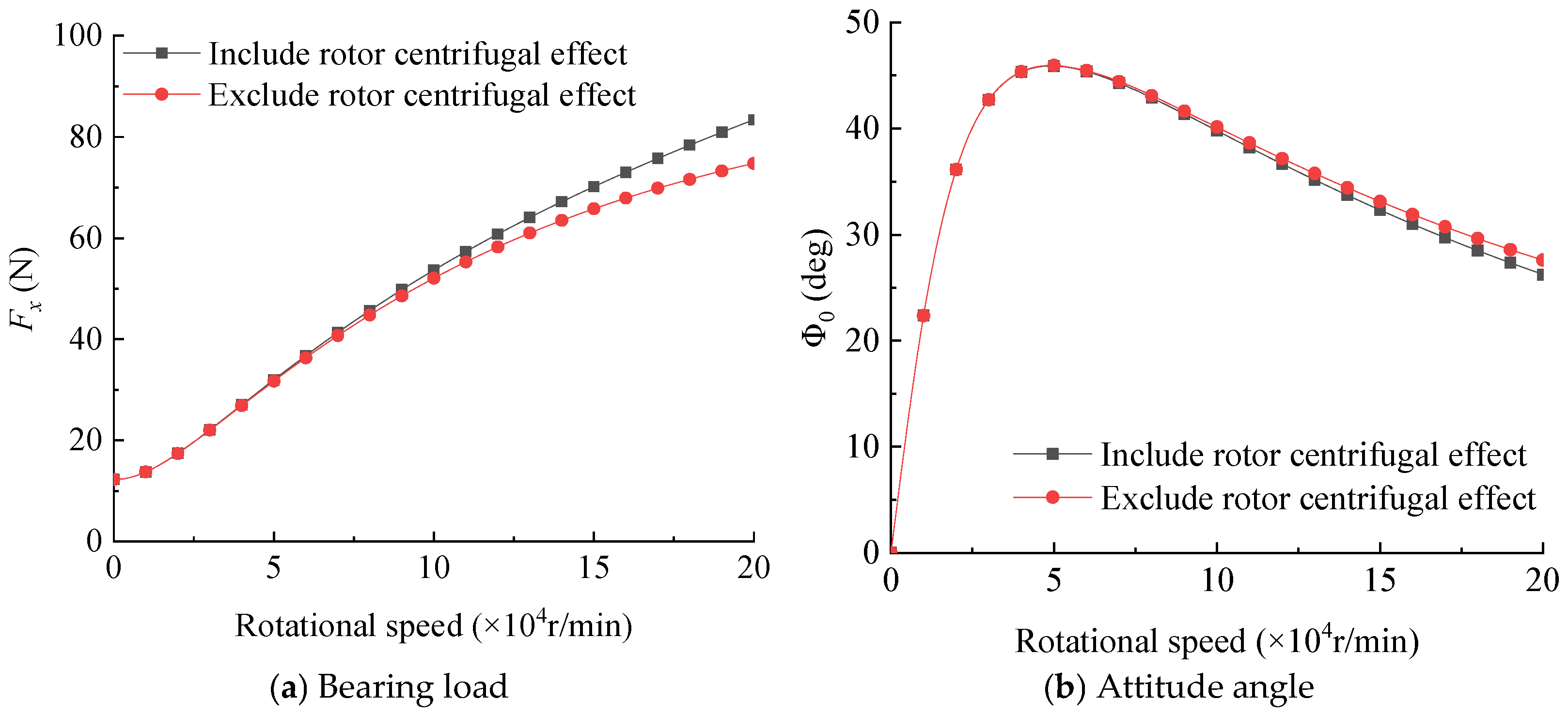
Figure 5 shows the bearing load and attitude angle of the high-speed porous gas bearing versus the rotational speed. It can be seen from Figure 5 that, as expected, the effect of the rotor’s centrifugal expansion on the load capacity and the attitude angle of the bearing increases with the rotational speed. Specifically, the rotor’s centrifugal expansion improves the bearing’s load capacity while reducing the attitude angle. As far as the attitude angle is concerned, the rotor’s centrifugal expansion improves the bearing’s dynamic stability, because the lower attitude means the lower tangential film force and thus a higher instability onset speed of self-excited vibration. The above results can be explained as follows: the centrifugal expansion of the rotor reduces the air film thickness, as illustrated in Figure 6, and consequently increases the load capacity of the bearing. In addition, a thinner gas film usually yields better bearing stability [33] despite the higher manufacturing cost.
Figure 5.
Bearing load and attitude angle versus rotational speed ( = 16 μm, = 12.5 mm, = 0.4, = = 0).
Figure 6.
Rotor centrifugal expansion and relative reduction in gas film thickness versus rotational speed ( = 16 μm, = 12.5 mm).
It should be particularly noted that for the studied bearing configuration, when the operating speed exceeds 90,000 rpm, the influence of the rotor centrifugal expansion effect on the bearing load-carrying performance begins to become significant. To design high-speed rotor systems supported by porous aerostatic bearings with greater accuracy and safety, the centrifugal expansion effect of the rotor should be incorporated into the dynamic modeling process.
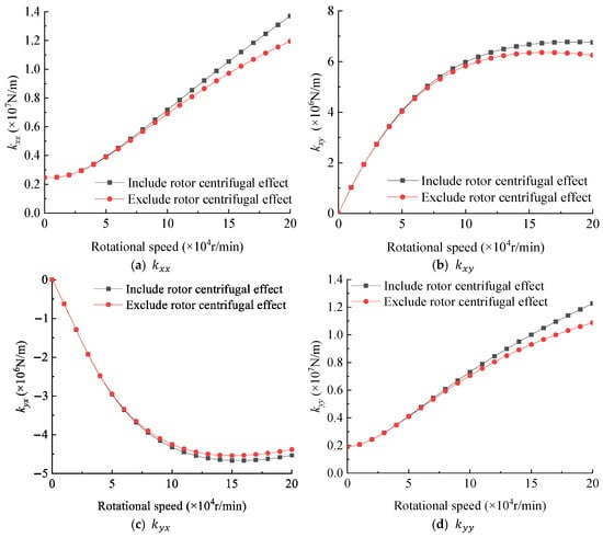
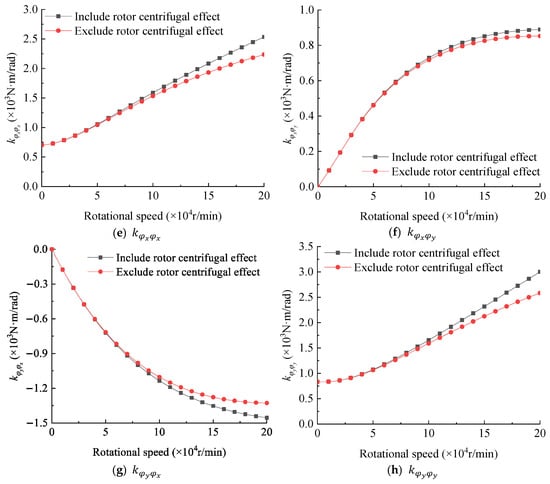
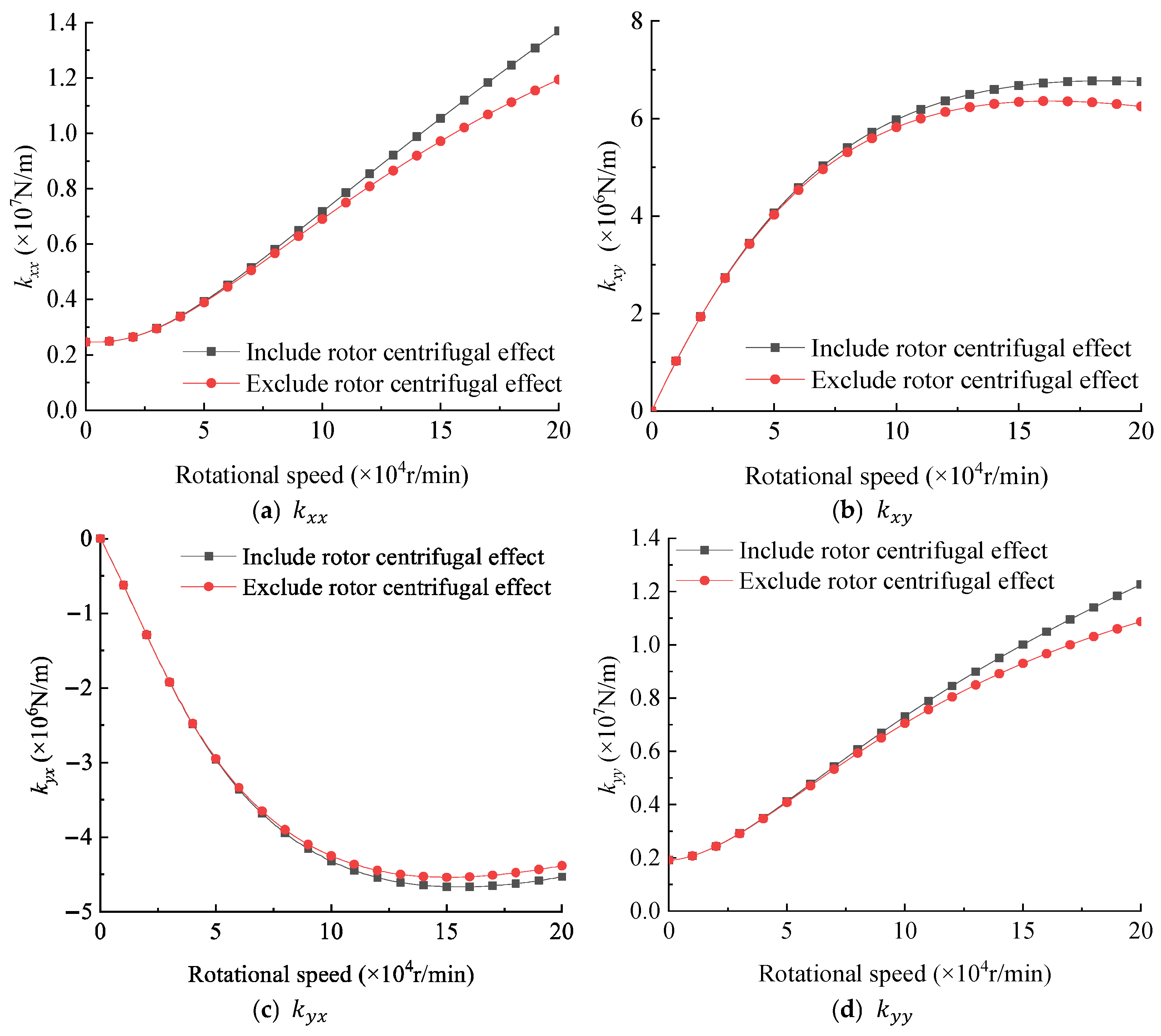
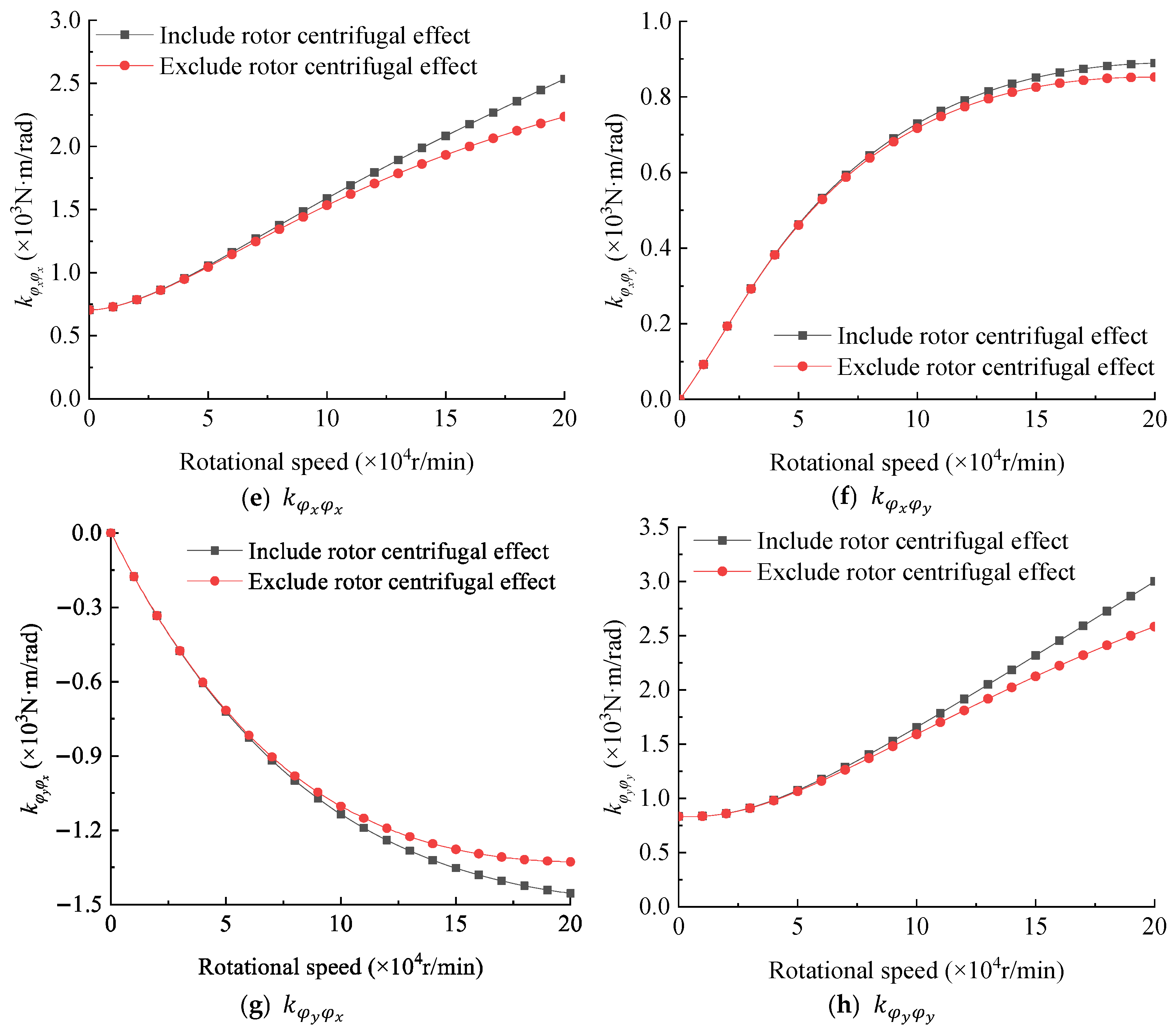
Figure 7 shows the eight main stiffness coefficients of the high-speed porous gas bearing versus the rotational speed. It can be observed from Figure 7 that all stiffness coefficients (except and ) increase with the rotational speed, but and first increase and then decrease with the rotational speed. Again, when the rotational speed exceeds 90,000 r/min, the improvement in stiffness coefficients due to the rotor’s centrifugal effect becomes prominent, and its magnitude of improvement gradually increases with rotational speed. At 200,000 r/min, the centrifugal effect increases the main stiffness coefficients of , , and by 14.7%, 12.9%, 13.4% and 16.2%, respectively. The results indicate that rotor centrifugal expansion greatly improves the stiffness of the porous gas bearing, especially at high rotational speeds.
Figure 7.
Stiffness coefficients of high-speed porous gas bearing versus rotational speed ( = 16 μm, = 12.5 mm, = 0.4, = = 0).
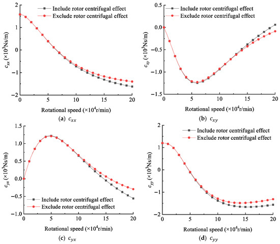
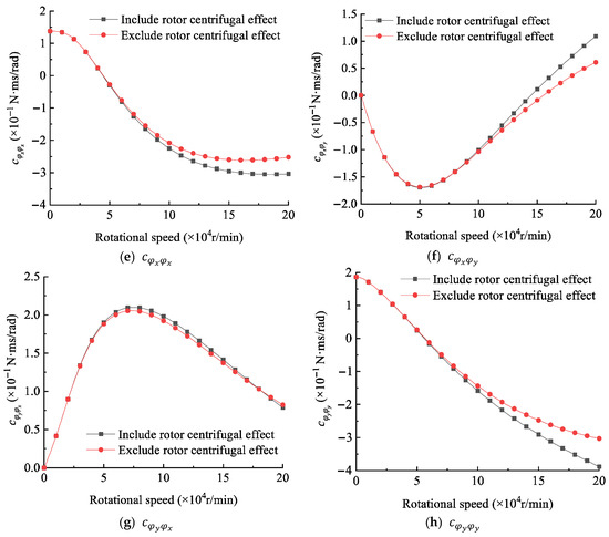
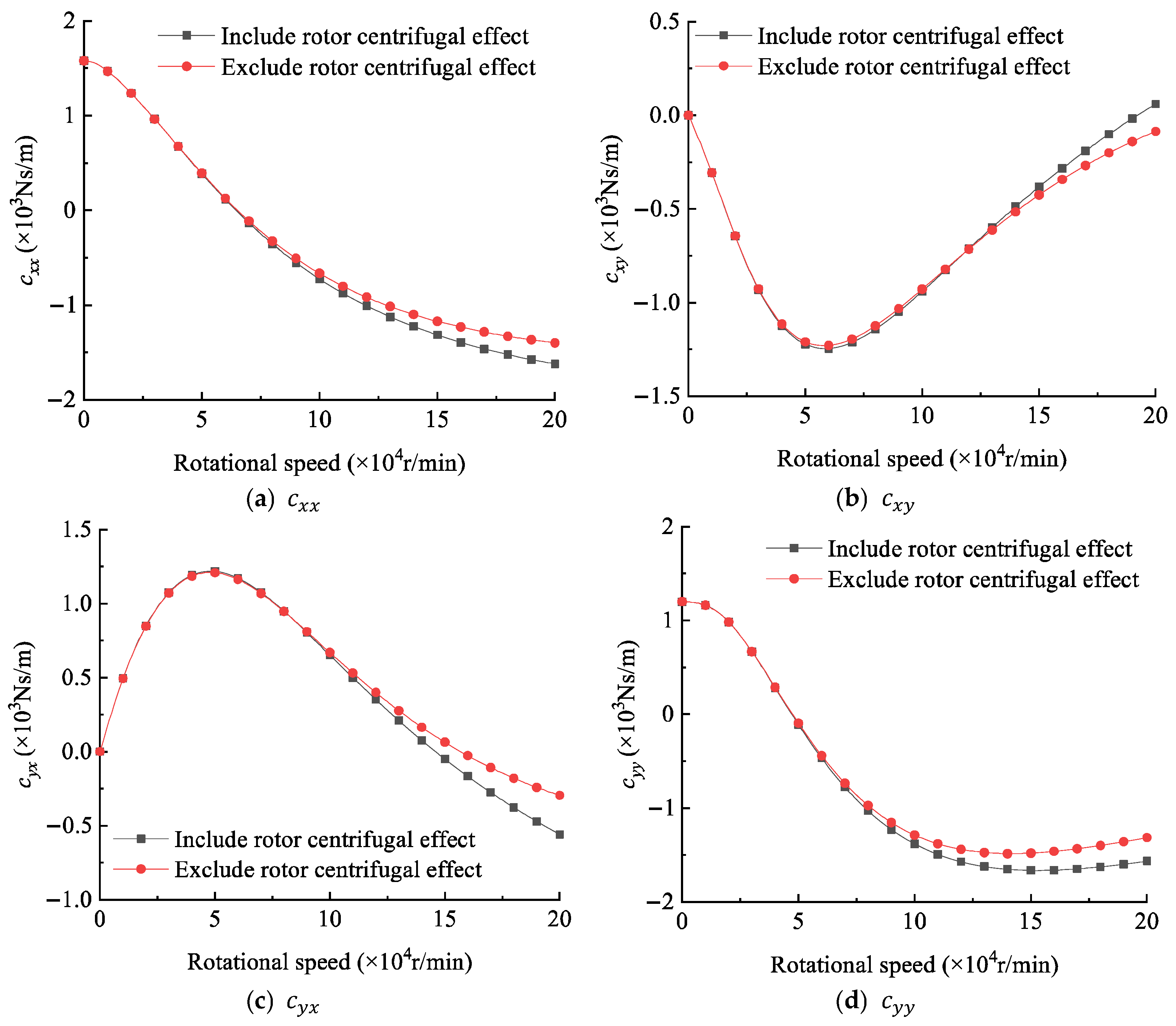
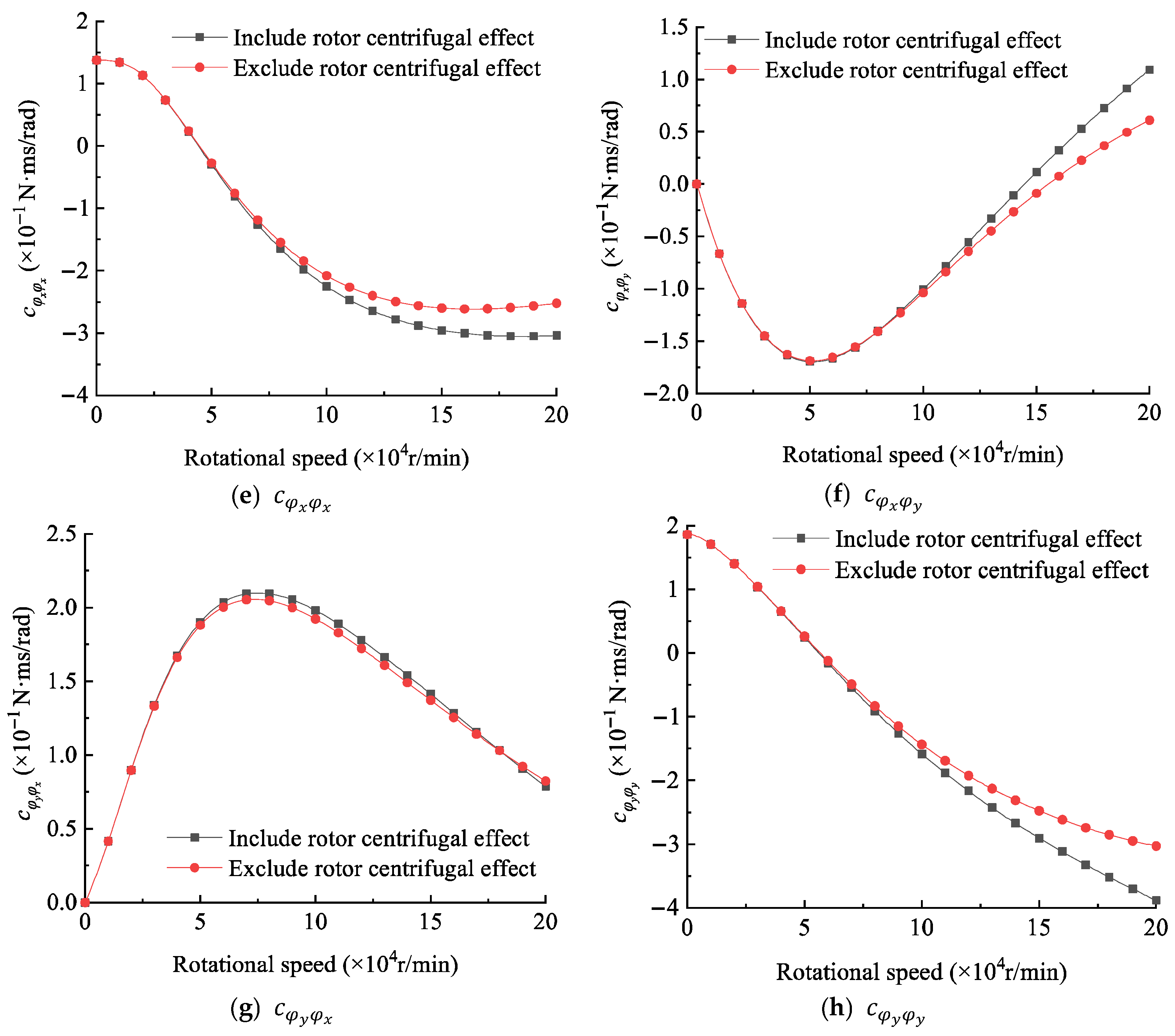
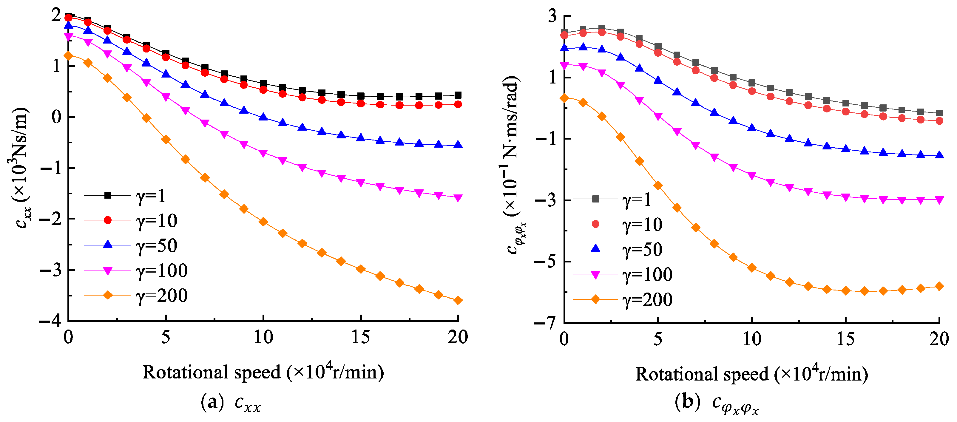
Figure 8 shows the damping coefficients of the high-speed porous gas bearing versus the rotational speed. It can be seen that the centrifugal effect enhances the main damping coefficients , , and by 15.75%, 19.08%, 20.55% and 28.18% at 200,000 r/min. It should be mentioned that, when the rotational speed exceeds 50,000 r/min, the damping coefficients , , and become negative. This is because the damping coefficients are closely related to the porosity parameter. As shown in Figure 9, when the porosity parameter is larger than 50, and become negative at high rotational speed. For the porous gas bearing analyzed in this section, the porosity parameter is 102.5. Therefore, the damping coefficients , , and become negative when the rotational speed exceeds 50,000 r/min.
Figure 8.
Damping coefficients of the high-speed porous gas bearing versus rotational speed ( = 16 μm, = 12.5 mm, = 0.4, = = 0).
Figure 9.
Damping coefficients of the porous gas bearing under different porosity parameters. ( = 16 μm, = 12.5 mm, = 0.4, = = 0).
The above phenomenon can be explained as follows: At high rotational speeds, increased porosity enhances gas storage and seepage in the porous bush, introducing a phase lag between pressure fluctuations and rotor motion. When this lag becomes significant, the gas film may supply energy to the rotor, leading to a reduction and, possibly, a sign reversal of the principal damping coefficient.
4.1.2. Rotor Diameter
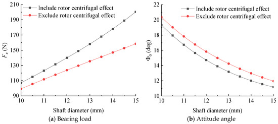
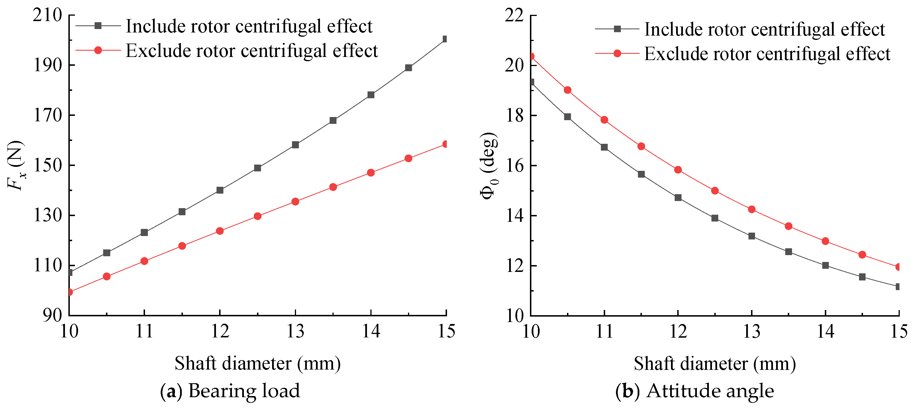
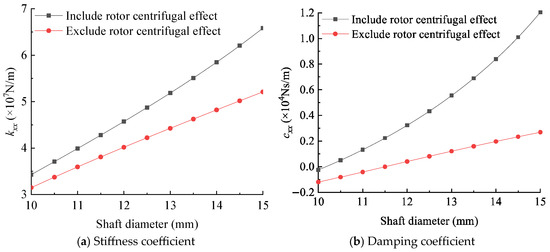
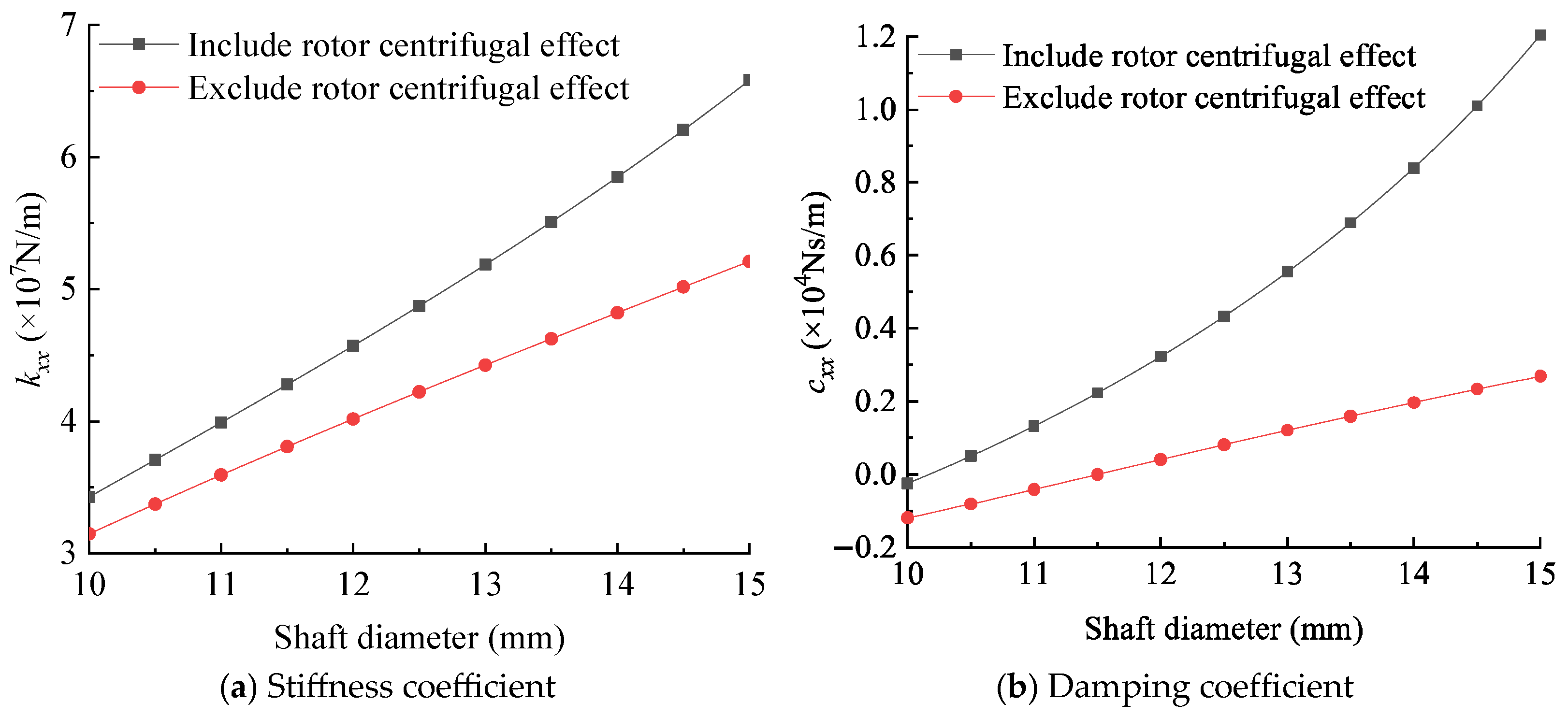
Figure 10 shows the bearing load and attitude angle of the high-speed porous gas bearing versus the rotor diameter. Figure 11 presents the bearing direct stiffness and damping coefficients versus the rotor diameter. The rotational speed is 200,000 r/min, the bearing clearance is 8 μm, the eccentricity ratio is 0.4, and the tilting angles are zero. The results indicate that, as the rotor diameter increases from 10 mm to 15 mm, the magnitude increases in the bearing load, the stiffness coefficient, and the damping coefficient due to the centrifugal effect in the case of 15 mm are larger than those in the case of 10 mm by 18.6%, 17.5%, and 267.5%, respectively. This is because, as Equation (8) shows, the centrifugal expansion of the rotor is proportional to the cube of its diameter. Therefore, the centrifugal expansion effect is more pronounced in larger-diameter rotors, resulting in a more significant reduction in gas film thickness. The gas film pressure consequently increases, leading to a marked rise in bearing load capacity, stiffness, and damping coefficients. It can also be noted that the bearing’s damping effect is more sensitive to the rotor centrifugal expansion. The reduction in gas film thickness significantly enhances the squeeze effect of the gas film during dynamic vibration. This effect increases the sensitivity of gas compressibility and transient mass flow to time-varying disturbances. Unlike static load capacity, the damping coefficient directly characterizes the gas film’s response to velocity perturbations and squeeze motion, making it particularly sensitive to clearance variations. As a result, centrifugal expansion leads to a much larger relative increase in damping compared to bearing load or stiffness.
Figure 10.
Bearing load and attitude angle versus shaft diameter ( = 200,000 r/min, c = 8 μm, = 0.4, = = 0).
Figure 11.
Dynamic coefficients of the high-speed porous gas bearing versus rotor diameter ( = 200,000 r/min, = 8 μm, = 0.4, = = 0).
4.2. Influences of Centrifugal Expansion on the Limit Bearing’s Minimum Film Thickness
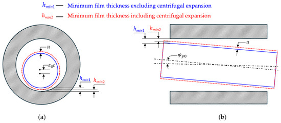
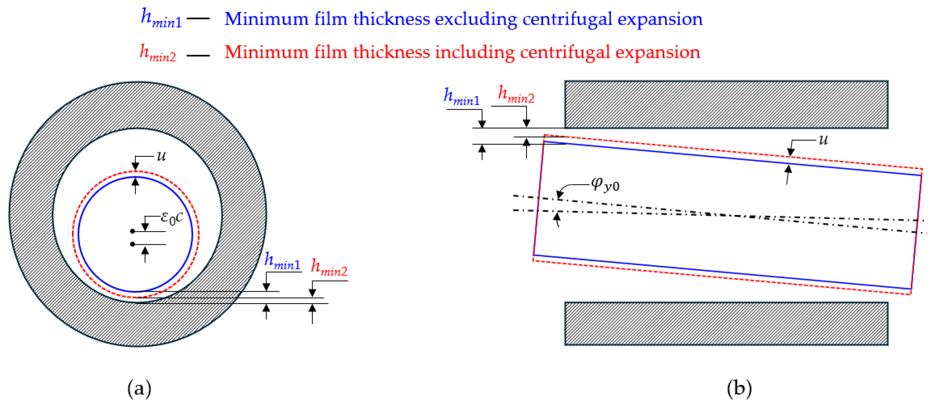
The centrifugal expansion of the rotor directly reduces the actual operating clearance of the bearing. Particularly when the bearing operates under large eccentricity or significant angular misalignment, a minimum gas film thickness occurs, as illustrated in Figure 12. Its magnitude is on the same order as the rotor’s centrifugal expansion, thereby posing a high risk of bearing rubbing incidents. Therefore, this section focuses on investigating the effect of centrifugal expansion on the limiting minimum gas film thickness of the bearing under eccentric or angular misalignment conditions.
Figure 12.
Effect of rotor centrifugal expansion on the minimum film thickness of the bearing under (a) eccentric and (b) angularly misaligned conditions.
To identify the limiting minimum gas film thickness using the program we developed, we leverage the characteristic that gas lubrication numerical calculations tend to diverge at high bearing numbers when extremely thin gas films are present [34]. Specifically, the bearing eccentricity or tilt angle is progressively increased until the program diverges, and the minimum gas film thickness corresponding to that eccentricity or tilt angle is then taken as the limiting value, despite real contact not occurring in the bearing. The tight bearing clearance and the large diameter ( = 8 μm, = 15 mm) are used in the simulation.
4.2.1. Eccentricity Ratio
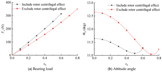
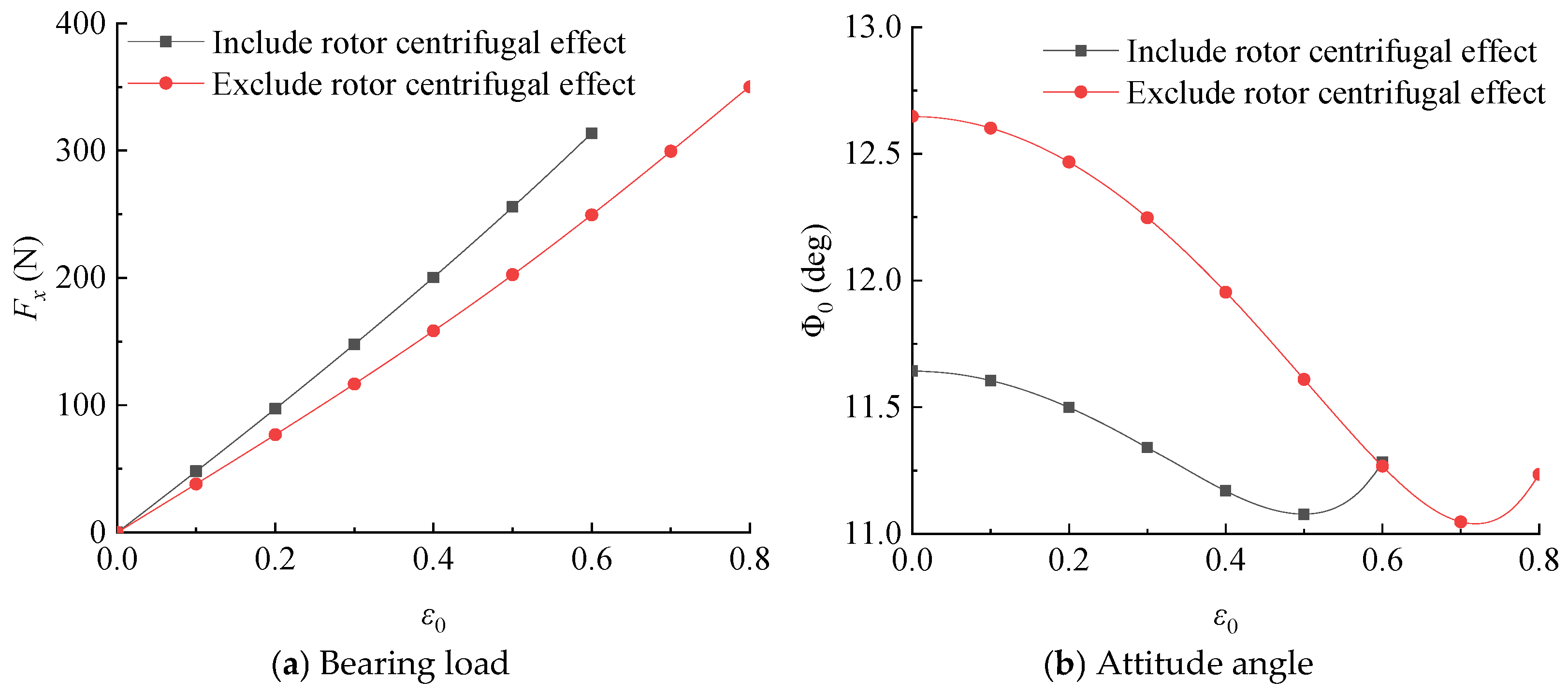
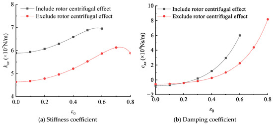
Figure 13 shows the bearing load and attitude angle of the high-speed porous gas bearing versus the eccentricity ratio. Figure 14 presents the bearing’s direct stiffness and damping coefficients versus the eccentricity ratio. Here, the bearing operates without the angular misalignment ( = = 0). The results indicate that the allowable eccentricity ratio, considering the centrifugal effect, is about 0.6, while the limit eccentricity ratio without considering the centrifugal effect is about 0.8. This implies that when designing a high-speed porous aerostatic bearing, if a lubrication model neglecting the centrifugal expansion effect of the rotor is used for analysis and calculation, it may lead to a designed bearing clearance with a high risk of rubbing. Such a design would be highly dangerous and unacceptable for high-speed rotating machinery supported by this type of bearing. This further illustrates that the centrifugal expansion effect of the rotor must be taken into account in the design of high-speed porous aerostatic bearing-rotor systems.
Figure 13.
Bearing load and attitude angle versus eccentricity ratio ( = 200,000 r/min, = 8 μm, = 15 mm, = = 0).
Figure 14.
Dynamic coefficients of high-speed porous gas bearing versus eccentricity ratio ( = 200,000 r/min, = 8 μm, = 15 mm, = = 0).
In addition, the bearing load increases with the eccentricity ratio, and the difference in the bearing load with and without considering the rotor centrifugal effect gradually increases with the eccentricity ratio. This is because the minimum gas film decreases with the increase in the eccentricity ratio; the effect of centrifugal expansion on the change in gas film thickness is more prominent.
4.2.2. Tilting Angle
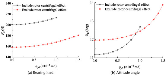
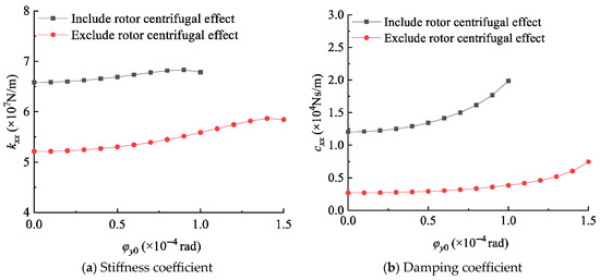
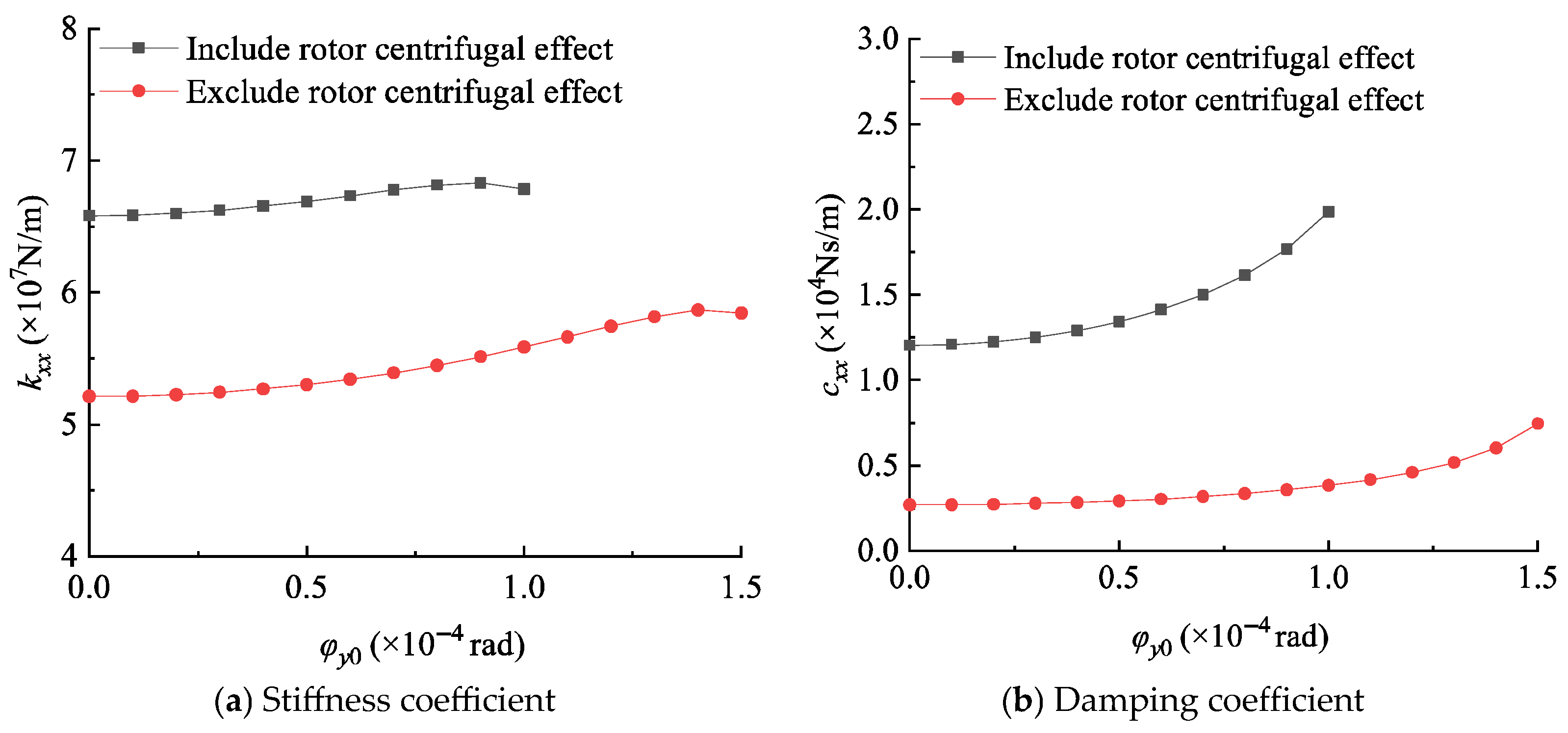
Figure 15 shows the bearing load and attitude angle of the high-speed porous gas bearing versus the tilting angle . Figure 16 displays the bearing’s direct stiffness and damping coefficients versus the tilting angle. Here, the tilting angle is 0 rad and the eccentricity ratio is 0.4. It can be observed from Figure 14 and Figure 15 that the minimum gas film thickness with and without centrifugal expansion is 1 × 10⁻⁴ rad and 1.5 × 10⁻⁴ rad, respectively, indicating that centrifugal expansion reduces the allowable tilting angles of the bearing by 33.3%. Similar to the eccentricity scenario, the centrifugal expansion of the rotor at high speeds also increases the risk of rotor-bush contact when the bearing operates under significant angular misalignment.
Figure 15.
Bearing load and attitude angle versus tilting angle ( = 200,000 r/min, = 8 μm, = 12.5 mm, = 0.4).
Figure 16.
Dynamic coefficients of high-speed porous gas bearing versus tilting angle ( = 200,000 r/min, = 8 μm, = 12.5 mm, = 0.4).
5. Conclusions
A theoretical model for the high-speed porous gas bearing, including the rotor centrifugal effect, is developed. By using the proposed model, the influence of rotor centrifugal expansion on the performance and allowable operational condition of the bearing is analyzed systematically. The following conclusions are drawn:
- (1)
- A 4-DOF model including the rotor centrifugal effect is established for the high-speed porous gas bearing, which can be used to numerically study the influence of the rotor centrifugal expansion on the operational performances of the high-speed porous gas bearing.
- (2)
- The bearing load and dynamic coefficients of the high-speed porous gas bearing are greatly improved by the rotor centrifugal effect, especially for the bearing with a large rotor diameter and small bearing clearance. For instance, in the case of the studied bearing with an 8 μm clearance and a 15 mm inner diameter, this effect becomes substantial and must be taken into account once the operating speed exceeds 900,000 r/min.
- (3)
- The centrifugal expansion effect of the rotor significantly reduces the minimum gas film thickness in bearings operating under conditions of large eccentricity or substantial angular misalignment, thereby increasing the risk of bearing rubbing failures. The centrifugal expansion effect of the rotor should be considered in the analysis and design of the rotor system with a high-speed porous gas bearing, particularly when the supported rotor may operate under significant eccentricity and angular misalignment.
Author Contributions
Conceptualization, S.L., H.Z. and X.H.; Methodology, S.L. and X.H.; Software, H.Z.; Formal analysis, S.L.; Investigation, Z.W.; Resources, X.H.; Data curation, Z.W.; Writing—original draft, S.L., H.Z. and X.H.; Writing—review & editing, S.L.; Visualization, Z.W.; Supervision, X.H.; Funding acquisition, S.L. All authors have read and agreed to the published version of the manuscript.
Funding
The authors gratefully acknowledge the support of the Fundamental Research Funds for the Central Universities through grant No. 309231C8806.
Data Availability Statement
The original contributions presented in the study are included in the article, further inquiries can be directed to the corresponding author.
Conflicts of Interest
The authors declare no conflict of interest.
Nomenclature
| Bearing clearance (m) | , | Auxiliary variables | |
| Damping coefficients (Ns/m), | Rotor diameter (m) | ||
| Elastic modulus of rotor (Pa) | Eccentricity | ||
| , | Forces along x and y Directions (N) | Thickness of porous bushing (m) | |
| , | Film thickness, | Bearing length-clearance ratio | |
| Stiffness coefficients (N/m), | Length of bearing (m) | ||
| , | Tangential coordinate, | , | Moments around and axes (Nm) |
| Pressure in gas film (Pa), | Pressure in porous bushing, | ||
| Ambient pressure (Pa) | , | Supply pressure, | |
| , | Dimensionless static pressure | , , , | Dimensionless perturbation pressure, |
| Rotor radius (m) | Radial position | ||
| , | Radial coordinate, | , | Time, |
| Radial deformation of rotor (m) | Rotor centrifugal expansion (m) | ||
| , , , | Equilibrium position (m) | Axial coordinate (m) | |
| Porosity parameter, | ,, , | Perturbation displacement (m) | |
| Radial stress | Tangential stress (Pa) | ||
| Eccentricity ratio, | Radial strain | ||
| Tangential strain | Viscosity of gas (Ns/m2) | ||
| Bearing number, | Feeding parameter, | ||
| Porosity of porous material | Poisson ratio of rotor | ||
| Density of rotor (kg/m3) | Permeability coefficient (m2) | ||
| Attitude angle (o) | Angular velocity (rad/s) |
References
- Wang, N.; Chen, H. A two-stage multiobjective optimization algorithm for porous air bearing design. Tribol. Int. 2016, 93, 355–363. [Google Scholar] [CrossRef] [Scilit]
- Cui, H.; Wang, Y.; Yue, X.; Huang, M.; Wang, W. Effects of manufacturing errors on the static characteristics of aerostatic journal bearings with porous restrictor. Tribol. Int. 2017, 115, 246–260. [Google Scholar] [CrossRef] [Scilit]
- Wu, Y.; Feng, K.; Zhang, Y.; Liu, W.; Li, W. Nonlinear dynamic analysis of a rotor-bearing system with porous tilting pad bearing support. Nonlinear Dynam. 2018, 94, 1391–1408. [Google Scholar] [CrossRef] [Scilit]
- PRODUCT. Available online: https://www.haozhihs.com/show.php?id=372 (accessed on 10 December 2025).
- Wardle, F. Ultra-Precision Bearings; Woodhead Publishing: Oxford, UK, 2015. [Google Scholar] [CrossRef] [Scilit]
- Cui, H.; Wang, Y.; Yue, X.; Huang, M.; Wang, W.; Jiang, Z. Numerical analysis and experimental investigation into the effects of manufacturing errors on the running accuracy of the aerostatic porous spindle. Tribol. Int. 2018, 118, 20–36. [Google Scholar] [CrossRef] [Scilit]
- Deng, X. A mixed zero-equation and one-equation turbulence model in fluid-film thrust bearings. ASME J. Tribol. 2023, 146, 034101. [Google Scholar] [CrossRef] [Scilit]
- Yoshimoto, S.; Tozuka, H.; Dambara, S. Static characteristics of aerostatic porous journal bearings with a surface-restricted layer. Proc. Inst. Mech. Eng. Part J J. Eng. Tribol. 2003, 217, 125–132. [Google Scholar] [CrossRef] [Scilit]
- Sneck, H.J.; Yen, K.T. The externally pressurized, porous wall, gas-lubricated journal bearing. I. ASLE Trans. 1964, 7, 288–298. [Google Scholar] [CrossRef] [Scilit]
- Sneck, H.J.; Elwell, R.C. The externally pressurized, porous wall, gas-lubricated journal bearing. II. ASLE Trans. 1965, 8, 339–345. [Google Scholar] [CrossRef] [Scilit]
- Su, J.C.T.; Lie, K.N. Rotor dynamic instability analysis on hybrid air journal bearings. Tribol. Int. 2006, 39, 238–248. [Google Scholar] [CrossRef] [Scilit]
- Elsharkawy, A.A.; Guedouar, L.H. Hydrodynamic lubrication of porous journal bearings using a modified brinkman-extended darcy model. Tribol. Int. 2001, 34, 767–777. [Google Scholar] [CrossRef] [Scilit]
- Wang, X.; Xu, Q.; Wang, B.; Zhang, L.; Yang, H.; Peng, Z. Numerical calculation of rotation effects on hybrid air journal bearings. Tribol. Trans. 2017, 60, 195–207. [Google Scholar] [CrossRef] [Scilit]
- Jiang, S.; Yang, S.; Xu, C. Static and dynamic characteristics of externally pressurized annular porous gas thrust bearings. Proc. Inst. Mech. Eng. Part J J. Eng. Tribol. 2016, 230, 1221–1230. [Google Scholar] [CrossRef] [Scilit]
- Pal, D.K.; Majumdar, B.C. Stability analysis of externally-pressurized gas-lubricated porous bearings with journal rotation part 1. Cylindrical whirl. Tribol. Int. 1984, 17, 83–91. [Google Scholar] [CrossRef] [Scilit]
- Rao, N.S.; Majumdar, B.C. Dynamic characteristics of gas-lubricated externally pressurized porous bearings with journal rotation: I. Wear 1978, 50, 59–70. [Google Scholar] [CrossRef] [Scilit]
- Naduvinamani, N.B.; Hiremath, P.S.; Gurubasavaraj, G. Squeeze film lubrication of a short porous journal bearing with couple stress fluids. Tribol. Int. 2001, 34, 739–747. [Google Scholar] [CrossRef] [Scilit]
- Bhattacharjee, B.; Chakraborti, P.; Choudhuri, K. Evaluation of the performance characteristics of double-layered porous micropolar fluid lubricated journal bearing. Tribol. Int. 2019, 138, 415–423. [Google Scholar] [CrossRef] [Scilit]
- Lee, C.; You, H. Geometrical design considerations on externally pressurized porous gas bearings. Tribol. Trans. 2010, 53, 386–391. [Google Scholar] [CrossRef] [Scilit]
- Boubendir, S.; Larbi, S.; Malki, M.; Bennacer, R. Hydrodynamic self-lubricating journal bearings analysis using rabinowitsch fluid lubricant. Tribol. Int. 2019, 140, 105856. [Google Scholar] [CrossRef] [Scilit]
- Hou, G.; Su, H.; Huang, Y.; Chen, C. An analysis method of pressure characteristic for cylindrical intershaft gas film seal considering centrifugal expansion, rotor misalignment, and precession. Proc. Inst. Mech. Eng. Part J J. Eng. Tribol. 2022, 236, 935–945. [Google Scholar] [CrossRef] [Scilit]
- Huang, X.; Lin, S.; Liang, J. Modelling approach of hybrid air herringbone grooved journal bearing considering the angular misalignment and centrifugal expansion. Tribol. Int. 2023, 189, 108928. [Google Scholar] [CrossRef] [Scilit]
- Scheidegger, A.E. The Physics of Flow Through Porous Media; University of Toronto Press: Toronto, ON, Canada, 2020. [Google Scholar] [CrossRef] [Scilit]
- Li, W.; Wang, S.; Zhao, Z.; Zhang, K.; Feng, K.; Hou, W. Numerical and experimental investigation on the performance of hybrid porous gas journal bearings. Lubr. Sci. 2021, 33, 60–78. [Google Scholar] [CrossRef] [Scilit]
- Rao, N.S. Analysis of the stiffness and damping characteristics of an externally pressurized porous gas journal bearing. ASME J. Lubr. Technol. 1977, 99, 295–301. [Google Scholar] [CrossRef] [Scilit]
- Mori, H.; Yabe, H.; Shibayama, T. Theoretical solution as a boundary value problem for externally pressurized porous gas-bearings. ASME J. Basic. Eng. 1965, 87, 622. [Google Scholar] [CrossRef] [Scilit]
- Jiang, S.; Lin, S.; Xu, C. Static and dynamic characteristics of externally pressurized porous gas journal bearing with four degrees-of-freedom. ASME J. Tribol. 2018, 140, 011702. [Google Scholar] [CrossRef] [Scilit]
- Sun, D. Analysis of the steady state characteristics of gas-lubricated, porous journal bearings. ASME J. Lubr. Technol. 1975, 97, 44–51. [Google Scholar] [CrossRef] [Scilit]
- Fourka, M.; Bonis, M. Comparison between externally pressurized gas thrust bearings with different orifice and porous feeding systems. Wear 1997, 210, 311–317. [Google Scholar] [CrossRef] [Scilit]
- Wang, C.; Lo, C.; Chen, C.O. Nonlinear dynamic analysis of a flexible rotor supported by externally pressurized porous gas journal bearings. ASME J. Tribol. 2002, 124, 553–561. [Google Scholar] [CrossRef] [Scilit]
- Su, J.C.T.; You, H.I.; Lai, J.X. Numerical analysis on externally pressurized high-speed gas-lubricated porous journal bearings. Ind. Lubr. Tribol. 2003, 55, 244–250. [Google Scholar] [CrossRef] [Scilit]
- Rohde, S.M.; Oh, K.P. Higher order finite element methods for the solution of compressible porous bearing problems. Int. J. Numer. Meth. Eng. 1975, 9, 903–911. [Google Scholar] [CrossRef] [Scilit]
- Liu, W.; Bättig, P.; Wagner, P.H.; Schiffmann, J. Nonlinear study on a rigid rotor supported by herringbone grooved gas bearings: Theory and validation. Mech. Syst. Signal Process. 2021, 146, 106983. [Google Scholar] [CrossRef] [Scilit]
- Kawabata, N. Numerical analysis of Reynolds equation for gas lubrication in a high Λ region. JSME Int. J. 1987, 30, 836–842. [Google Scholar] [CrossRef] [Scilit]

Disclaimer/Publisher’s Note: The statements, opinions and data contained in all publications are solely those of the individual author(s) and contributor(s) and not of MDPI and/or the editor(s). MDPI and/or the editor(s) disclaim responsibility for any injury to people or property resulting from any ideas, methods, instructions or products referred to in the content. |
© 2026 by the authors. Licensee MDPI, Basel, Switzerland. This article is an open access article distributed under the terms and conditions of the Creative Commons Attribution (CC BY) license.