Abstract
Wear and overheating in cycloidal systems significantly affect motion transmission efficiency, component lifespan, and maintenance costs. Numerous solutions have been proposed in the patent literature to address these issues. This paper identifies, analyzes, and classifies these solutions based on their working principles, strategies (Preventive, Compensative, Mitigative), and implementation methods. The results indicate that preventive strategies are predominant, mainly through friction reduction achieved via rolling elements. Compensative strategies rely on lubrication, while mitigative strategies, though rare, involve restoring contact surfaces through reshaping. This review serves as a comprehensive reference for the development of new solutions in the field.
1. Introduction
Cycloidal drives, alternatively referred to as cycloidal reducers or cycloidal speed reducers, represent a class of precision gear systems characterized by their exceptional torque density, compact form factor, and remarkable durability. In contrast to conventional gear reducers (including planetary or spur gear systems), cycloidal drives function through an eccentric cam mechanism that interfaces with cycloidal discs, thereby enabling smooth motion transmission with minimal backlash and outstanding resistance to shock loads [1,2,3]. These distinctive features make them particularly suitable for applications that demand precise motion control, high operational efficiency, and extended service life under rigorous operating conditions.
Notwithstanding their superior performance characteristics, cycloidal drives are subject to significant technical challenges associated with wear phenomena and thermal effects, both of which can adversely affect their operational performance and service longevity. These challenges predominantly originate from the system’s complex mechanical interactions and substantial load-bearing requirements. The primary contributing factors include sliding friction mechanisms, elevated contact stresses, lubrication system failures, alignment inaccuracies coupled with manufacturing tolerances, hysteresis-related energy losses, and insufficient thermal dissipation capabilities.
The resolution of these technical challenges assumes critical importance for ensuring prolonged operational reliability in demanding applications such as robotic systems and heavy industrial machinery. The current body of scientific literature reflects substantial research efforts directed toward the development of lubrication modeling approaches and predictive wear analysis methodologies applicable during the initial design phases. For example, Maccioni and Concli [4] offer a comprehensive and contemporary review of computational fluid dynamics (CFD) techniques, encompassing both mesh-based and meshless approaches, for the analysis of lubricated mechanical systems. This work systematically categorizes their respective applications, functional capabilities, and inherent limitations while concurrently assessing their accuracy and computational complexity in the context of gearbox, bearing, and pump modeling. Furthermore, Li et al. [5] introduce a wear prediction model specifically designed for cycloid drives, incorporating Hertzian contact theory and Archard’s wear equation. This investigation methodically examines the influence of tooth profile modifications, applied torque levels, rotational speed parameters, and eccentricity conditions on wear depth characteristics, thereby providing valuable insights for gear durability enhancement and design optimization. The work of Wang et al. [6] presents a sophisticated geometric model focused on cycloid-pin gear meshing dynamics, with particular emphasis on load distribution analysis, transmission error quantification, and wear pattern identification. This study successfully pinpoints critical wear locations that significantly affect reducer accuracy and operational lifespan, while simultaneously offering practical recommendations for gear design improvement. Most recently, Vasić et al. [7] have developed an advanced thermal model for cycloidal reducers capable of predicting power loss characteristics and equilibrium temperature distributions, with experimental validation conducted through infrared thermography techniques. This research addresses a significant knowledge gap in thermal analysis methodologies for such drive systems, delivering practical design guidelines while clearly identifying areas requiring additional research refinement. Finally, research on materials and related surface treatments also contributes to mitigating wear and overheating. This is exemplified by the techniques presented in [8], where a microindentation texturing technique significantly lowers the coefficient of friction by up to 65%, which directly reduces the heat generated from sliding contact. This friction reduction mitigates the adhesive wear and thermal stress that lead to premature failure.
Concurrently with the development of increasingly sophisticated simulation methodologies and analytical tools, research initiatives focused on specialized solutions for mitigating these technical challenges have experienced notable acceleration, particularly during the past decade. This progress has been facilitated by the availability of progressively more accurate predictive assessment capabilities. However, existing scientific literature lacks comprehensive critical analyses that offer a clear and systematic overview of the developed solutions.
Within this context, the primary objective of the current work is to address this knowledge gap by providing a concise yet thorough synthesis of the evolutionary progression of results obtained from creative engineering efforts specifically targeting wear and thermal management challenges. The authors believe that this contribution will not only consolidate existing knowledge on developed solutions (including their advantages and limitations) but also serve as a catalyst for innovation by building upon established technical achievements.
To achieve these research objectives, the authors have elected to focus exclusively on technical documentation available in patent databases. While it must be acknowledged that patents do not constitute empirical validation of the functionality or performance characteristics of claimed inventions, they nevertheless represent an extensive repository of technical knowledge. This repository is a fundamental resource for creative activities forming the foundation of innovation in engineering design.
Despite their primary legal function as protective instruments, patents effectively document the historical progression of technological problem-solving approaches, encapsulating millions of disclosed methodologies, mechanical configurations, and incremental advancements spanning all conceivable technical fields. This comprehensive technical database offers unique value to engineering professionals and designers. Through systematic patent analysis, practitioners can gain key insights into development trends, alternative technical solutions, and problem formulation strategies. This knowledge base serves as a powerful stimulus for innovation. It enables designers to avoid redundant development efforts, identify unexplored areas for novel solutions, comprehend competitive technological landscapes, and recognize potential intellectual property conflicts at early development stages. The patent analysis process frequently stimulates analogical reasoning processes, where solutions from one technical domain inspire breakthrough innovations in another.
Moreover, patent collections form the empirical foundation for systematic innovation theories that have gained substantial traction in industrial practice. The most prominent example is TRIZ (the Russian acronym for Theory of Inventive Problem Solving) [9]. TRIZ, developed by Genrich Altshuller through the exhaustive analysis of hundreds of thousands of patents, identifies recurring patterns in inventive solutions and universal principles governing technological evolution.
With specific reference to the current investigation, patents are systematically examined to identify alternative solutions specifically targeting wear and thermal management issues in cycloidal reduction systems. The research aims to comprehensively map documented inventive outcomes to identify both prevalent and uncommon solutions, characterizing them according to implementation strategies, targeted system components, and operational methodologies through which they achieve their effects on wear and thermal performance. Since the stated objective is to map inventive solutions across various levels, their validation and comparison through experimental or numerical activities does not fall within this scope. This is done with a clear awareness that some solutions will undoubtedly produce better effects and be more efficient than others.
The document is organized as follows: Section 2 details the methodological framework employed for relevant patent document identification. Section 3 provides a comprehensive summary of key findings, while Section 4 presents a critical analysis and discussion of results. Finally, Section 5 articulates the principal conclusions and their implications for future research and development.
2. Research Method
This section describes the research approach used to achieve the objective introduced in the previous section. Specifically, it outlines the method employed for retrieving relevant patent documents and the model used to classify the identified technical solutions. The research method employed in this study aligns with the PRISMA (Preferred Reporting Items for Systematic Reviews and Meta-Analyses) criteria, ensuring transparency, reproducibility, and systematic rigor. In Figure 1, the flowchart of the research method, according to PRISMA guidelines, is reported.
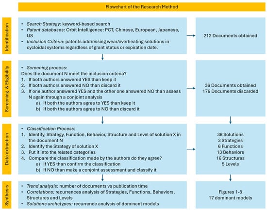
Figure 1.
Flowchart of the research method according to PRISMA guidelines.
2.1. Search and Screening of Relevant Patent Documents
The documentary research was conducted using the traditional keyword-based approach, with carefully formulated terms connected by logical operators to construct a query for interrogating the documentary databases. Specifically, the query used is reported below:
((CICLOIDAL OR CYCLOIDAL GEAR OR CYCLOIDAL SPEED REDUCER OR CYCLOIDAL TRANSMISSION OR CYCLOIDAL DRIVE OR CYCLOID SPEED REDUCER OR CYCLO GEAR REDUCER OR CYCLOIDAL GEARBOX OR CYCLOIDAL GEAR MECHANISM OR CYCLOID DRIVE OR CYCLOID)/TI/AB AND ((OVERHEAT OR THERMAL RUNAWAY OR TEMPERATURE RISE OR COOLING FAILURE OR THERMAL OVERLOAD OR THERMAL FAILURE OR OVERHEATING OR HIGH TEMPERATURE OR HEAT STRESS OR HEAT EXHAUSTION OR EXCESSIVE HEAT)/TI/AB) OR ((WEAR)/TI/AB))
The keyword search was performed in the “Title” (TI) and “Abstract” (AB) fields of the documents to expedite the process. As can be seen, the query was intentionally composed of a broad range of synonyms connected by OR operators, derived from the expansion of the terms “CICLOIDAL,” “OVERHEAT,” and “WEAR.” This approach ensures a general search scope, thereby increasing the likelihood of retrieving the highest possible number of relevant documents. However, such a method inevitably yields a very large number of results with significant noise—comprising non-relevant documents—thus requiring greater effort in the post-processing phase, particularly during document screening.
Concerning the research objectives, no temporal restrictions were imposed, nor were there any criteria to discriminate between granted and non-granted patents, or between valid and expired patents, as the focus was solely on the claimed solution.
The search process was implemented using Orbit Intelligence, version 2.0.0, a premium patent search, analytics, and intellectual property (IP) management software developed by Questel, a global leader in IP solutions. This platform is widely used by corporations, law firms, R&D teams, and universities for in-depth patent research, competitive intelligence, and innovation strategy. The documentary database interrogated was the one provided by the search software, which offers full-text coverage of the Patent Cooperation Treaty (PCT), Chinese, European (EP), Japanese, and US patent collections, along with several other primarily European databases.
The screening criterion employed to identify relevant documents was to consider only those patents whose inventions explicitly addressed solutions related to wear and/or overheating issues in cycloidal systems. Relevance assessment was based on the abstract, the drawbacks and advantages of prior art, as well as the invention’s subject matter. To ensure objectivity, both authors jointly conducted the screening process to reach a validated result.
2.2. Classification of the Relevant Solutions
To analyze and discuss the solutions present in the state of the art according to the objectives of this work, a descriptive model is required to highlight:
- The objective of the technical solution.
- The intervention method, i.e., how the solution is activated, operates, and is implemented within the system itself.
- The level at which the solution acts, meaning which part of the system it affects.
Various contributions in the literature help elucidate cause-effect relationships within technical systems and at different levels. This research adopts the logic suggested by the TRIZ System Operator [10,11], which allows for the classification of a solution based on:
- The strategy employed to address the problem, which may be:
- Preventive: if the solution intervenes by eliminating the causes that generate the problem.
- Compensatory: if the solution intervenes by restoring performance negatively affected by the problem when it produces its adverse effects.
- Mitigative: if the solution intervenes solely on the effects produced by the problem itself.
- The level of detail at which the solution operates, i.e., whether it affects:
- The entire system (considered as a cycloidal reducer).
- Only certain components, or
- external elements not part of the system but interacting with it within the operational environment.
For the sake of clarity, in the following the authors provide some examples of possible classifications:
- A solution aimed at reducing the friction coefficient between the contact surfaces of system elements in relative motion would be classified as Preventive, as it seeks to eliminate (or at least mitigate) a physical parameter that is the root cause of wear and overheating, acting at the subsystem level of the sliding surfaces.
- A solution that dissipates heat by removing the thermal power generated during the reducer’s operation would be considered Compensatory, as it aims to restore the system’s ideal operating conditions when the problem produces its undesired effect, intervening at the level of the reducer as a whole.
- Finally, a solution that compensates for the play resulting from wear in moving parts would be classified as Mitigative, since its objective is to restore system functionality after the problem’s effects have occurred, without addressing the root causes, thus acting at the level of the worn surfaces.
Regarding the classification of solutions based on their operational modes, several models can be considered as references, particularly in the field of Engineering Design [10,12,13].
For the classification purposes of this work, the authors adopted the FBS (Function-Behavior-Structure) model [14] as a reference, as it is a widely used framework in design and engineering for systematically analyzing and developing systems or products. This model assists in representing a technical system across different levels of abstraction. Specifically, it decomposes a system into three core aspects:
- Function: the purpose or goal of the system, which constitutes the motivation for its existence and thus represents the need to be fulfilled.
- Behavior: the processes or actions that achieve the function, i.e., the operational mode through which the system attains its objective and produces the desired effect.
- Structure: the physical components and their relationships, meaning the system’s parts that, through their mutual interactions, implement the considered behavior.
For clarity, it is useful to provide classification examples based on this model. For instance, a solution aimed at reducing friction by transforming it from sliding to rolling through the use of rolling elements would be classified as follows: Function: “Reduce friction”; Behavior: Based on “rolling friction”; Structure: A physical configuration that incorporates rolling elements (such as balls, cylinders, or cones) between the surfaces of relatively moving components.
Conversely, a solution that employs the lubricant inside a gearbox as a heat-dissipating fluid, circulated via a pump and flow channels machined into the gearbox housing, would be characterized by: Function: “Cooling”; Behavior: “Heat exchange”; Structure: A pump, driven by the gearbox itself, which forces the lubricant through cooling channels integrated into the gearbox casing.
In conclusion, according to the above definitions, each technical solution deemed relevant will be classified according to: Strategy (Str), which could be Preventive (P), Compensative (C) or Mitigative (M), Function (F), Behavior (B), Structure (S) and Level (L). By analyzing the information available in description and drawings it is therefore possible to identify the most recurrent solution archetypes.
3. Results
The research retrieved 212 patent documents, of which 36 deemed relevant according to the criteria defined in the previous section. The relevant documents have been referenced in Appendix A through a number ranging from 1 to 36.
The trend of solutions over the last 20 years is shown in Figure 2, which depicts the cumulated number of patents at a specific point in time by considering the 36 relevant patents. The trend is built through the following formula:
Cumulated Patents (Year T) = Cumulated Patents (Year T−1) + Patents Granted (Year T)
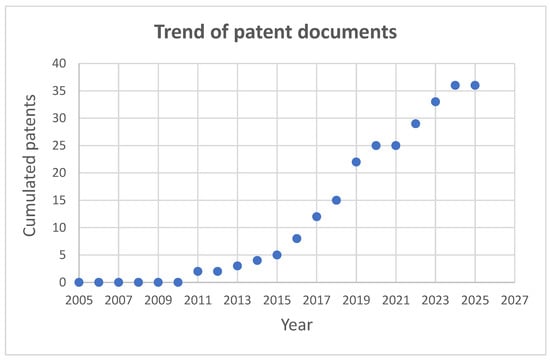
Figure 2.
Cumulated number of patents at a specific point in time by considering the 36 relevant patents (period 2005–2025).
The path can give an idea of the inventive activity on the topics “wearing” and “heating”. As shown, these topics seem to be still relevant as the trend is growing (the last two years are not very significant due to the publication time of the patent procedures). As can be seen, the trend begins around the end of the first decade of the 2000s, with no significant contributions found in the preceding years.
To facilitate the discussion of the results, the data collected from the research has been organized into charts, tables, and maps to highlight correlations and dependencies between strategies, functions, behaviors, solution structures identified, and the system levels they affect. Below, a deep description of the results is provided, which will serve the subsequent discussion section.
3.1. Classification of the Solutions
Considering the intervention strategy, Figure 3 shows that 80% of the solutions are based on the preventive strategy, whereas the other two strategies are used to a lesser extent.
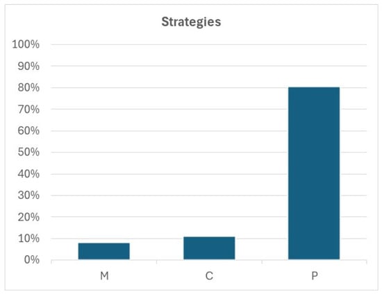
Figure 3.
Distribution of the three intervention strategies on wearing and overheating, which have been identified in the relevant patent documents. M = Mitigative, C = Compensative; P = Preventive.
Table 1 lists the functions that have been identified in the solutions judged as relevant. These functions have been classified into six main categories, which are described below:
- •
- F1: reduction of the friction that affects the contact surfaces of the system elements.
- •
- F2: increase the resistance of the system elements.
- •
- F3: increase the backlash between the contact surfaces, especially in reference to the toothed elements.
- •
- F4: reduce the backlash between the contact surfaces of the toothed elements, which is generated by wearing and heating.
- •
- F5: cool the system.
- •
- F6: restore the ideal configuration of the system after experiencing the effect of wearing and heating.

Table 1.
Functions categories (F) implemented by the relevant solutions and related patent documents from which they have been retrieved, as referenced in Appendix A.
Table 1.
Functions categories (F) implemented by the relevant solutions and related patent documents from which they have been retrieved, as referenced in Appendix A.
| Item | Description | Patent Documents |
|---|---|---|
| F1 | Friction reduction | 3, 4, 5, 6, 7, 10, 11, 12, 13, 14, 15, 16, 18, 21, 23, 28, 29, 30, 31, 32, 33, 35, 36 |
| F2 | Increase resistance | 8, 17, 34 |
| F3 | Increase backlash | 9, 24, 25, 27 |
| F4 | Backlash recovery | 19, 22 |
| F5 | Cooling | 1, 2, 26 |
| F6 | Restore the toothed surfaces | 20 |
Table 2 summarizes the behaviors used in the relevant solutions to obtain the desired effects of the functions listed in Table 1. The analysis highlighted the following thirteen categories of behavior:
- •
- B1: substituting the sliding friction between the contact surfaces of the elements that are in relative motion with rolling friction.
- •
- B2: reducing the friction between the contact surfaces of the elements that are in relative motion by using lubrication.
- •
- B3: Introducing a backlash between the contact surfaces of the toothed elements that consider the deformations caused by heating and loads. In this way, during operation, these elements will recover the backlash inserted after warming up, without getting stuck or excessively increasing the contact forces.
- •
- B4: reducing the friction between the contact surfaces of the elements that are in relative motion by adopting materials having low friction properties.
- •
- B5: using the thermal exchange to dissipate the thermal energy generated during the working phase.
- •
- B6: making the contact surfaces of the elements that are in relative motion capable of recovering the unwanted backlash generated by wearing.
- •
- B7: reducing the friction between the contact surfaces of the elements that are in relative motion by exploiting the properties of the surfaces, advantageously modified to entrap the lubricant.
- •
- B8: improving the wearing and heating resistance by changing the physical and chemical properties of the materials through specific thermal treatments, performed locally on the contact surfaces.
- •
- B9: reducing the friction between the contact surfaces of the elements that are in relative motion not only by exploiting the behavior B1 but also by decreasing the number of the contact surfaces, to concentrate the effects on a small number of elements.
- •
- B10: this behavior suggests removing the material scraps generated by wearing to reduce their contribution to friction.
- •
- B11: it suggests designing the tooth profile by considering how it will deform during the working phase due to wear and heating. In this way, these effects can be preliminarily considered, starting from a tooth shape that will then assume the ideal shape during the operations.
- •
- B12: this approach suggests addressing the effects of wear by making the components, or their parts, easily replaceable.
- •
- B13: balancing of the contact forces through a more uniform distribution of the contact forces on the whole system.
Table 2.
Behaviors (B) used in the relevant solutions to implement the functions (F), and related patent documents from which they have been retrieved, as referenced in Appendix A.
Table 2.
Behaviors (B) used in the relevant solutions to implement the functions (F), and related patent documents from which they have been retrieved, as referenced in Appendix A.
| Item | Description | Patent Documents |
|---|---|---|
| B1 | Rolling friction | 4, 5, 10, 13, 15, 18. 21, 28, 29, 30, 31, 35, 36 |
| B2 | Lubrication | 3, 7, 11 |
| B3 | Introducing a predetermined backlash | 24, 25, 27 |
| B4 | Friction materials with low friction coefficient | 16, 32, 33 |
| B5 | Thermal exchange | 1, 2, 26 |
| B6 | Regulation of the position of the contact surface | 19, 22 |
| B7 | Lubrication + Surface state | 14, 23 |
| B8 | Improved material through thermal treatment | 8, 17, 19, 22 |
| B9 | Rolling friction + reduction of the contact surfaces | 6 |
| B10 | Remove wear material scraps | 12 |
| B11 | Optimize the teeth under the operative conditions | 9 |
| B12 | Easy substitution of the contact surface | 20 |
| B13 | Balance of the contact forces | 34 |
Table 3 presents the structures used by the relevant solutions to implement the behaviors listed in Table 2. Overall, the study highlighted sixteen structures categories that are described in the following:
- S1: this structure entails the insertion of rolling elements between the contact surfaces that are in relative motion to transform sliding friction into rolling friction.
- S2: this configuration suggests introducing tolerances between the moving parts, to consider the deformations due to contact forces and heating.
- S3: it is based on antifriction bearings between, placed between pins and holes to reduce the sliding friction coefficient. This structure refers to the extraction of the output motion through the classical pins-holes mechanism.
- S4: the structure is based on a propeller that moves a cooling fluid (that could also be the lubricant) inside channels and holes advantageously realized and distributed inside the components of the system.
- S5: the solution employs an Oldham joint to extract the output motion whose configuration uses bearings on the surfaces of the prismatic guides to transform the sliding friction into rolling friction.
- S6: the contact surfaces of the components that are in relative motion are tapered to easily recover the backlash generated by wearing; in such a way it is possible to restore the ideal contact.
- S7: the state of the contact surfaces is made porous to contain and entrap the lubricant, the components are obtained through sintering processes.
- S8: the system has channels, holes and features to better spread the lubricant on the moving elements (bearings of the eccentric shaft, contact surfaces between pin and holes, contact surfaces of teeth and rollers).
- S9: the solution entails a multistage reducer having a predetermined angular offset of the eccentric wheels, to optimize distribution and balancing of the contact forces.
- S10: the toothed wheels have external rings to hold the teeth, which can be easily dismantled when they become damaged for any reason.
- S11: the distribution of the hardness of the teeth contact surfaces is tuned according to the distribution of the contact pressure acting on them.
- S12: the solution is based on the use of one or more magnets placed inside the reducer to capture the material scraps and to reduce their contribution to wearing and heating.
- S13: the design of the contact surface of the teeth is made by taking into consideration the distribution of the contact pressure. Therefore, the teeth profile can deform according to the loading behavior and become of the ideal shape during the working phase.
- S14: the contact surfaces of the teeth are designed in a way that facilitates the thermal treatment during the manufacturing process. This allows a better distribution of the hardness along the contact surface according to the contact pressure distribution.
- S15: the solution uses a push rod with a bearing at the tip that acts as a toothed wheel, and it is moved by the eccentric shaft. Therefore, the number of teeth is reduced to one and the push rod that rotates eccentrically.
- S16: this solution suggests using lubricants with a customized chemical formulation, capable of reducing the sliding friction coefficient drastically as well as the heating of the system.
Table 3.
Structures (S) of the relevant solutions and related patent documents from which they have been retrieved, as referenced in Appendix A.
Table 3.
Structures (S) of the relevant solutions and related patent documents from which they have been retrieved, as referenced in Appendix A.
| Item | Description | Patent Documents |
|---|---|---|
| S1 | Rolling elements between fixed and moving parts | 4, 5, 10, 13, 15, 18, 21, 28, 30, 31, 36 |
| S2 | Moving part with tolerances predetermined on the overall volume of the components | 24, 25, 27 |
| S3 | Antifriction bearings between pin and holes | 16, 32, 33 |
| S4 | Propeller, cooling fluid and refrigeration holes and channels | 1, 2, 26 |
| S5 | Oldham joint with bearings | 29, 35 |
| S6 | Conical surfaces to recover the backlash due to wear | 19, 22 |
| S7 | Porous contact surfaces to contain the lubricant | 14, 23 |
| S8 | System to better spread the lubricant on the contact surfaces | 7, 11 |
| S9 | Multi stages reduction with the introduction of an angular offset of the eccentricity | 34 |
| S10 | External surfaces of the toothed wheels easily replaceable | 20 |
| S11 | Different areas of the tooth surface have different hardness | 17 |
| S12 | Magnets positioned inside the system to capture the material scraps | 12 |
| S13 | Design of the tooth surface | 9 |
| S14 | Surfaces designed to facilitate the thermal process during the manufacturing | 8 |
| S15 | Rotating push rod having a bearing | 6 |
| S16 | Lubricant with specific composition to reduce friction and thermal heating | 3 |
Eventually, Table 4 shows the system levels on which the solutions are focused. Overall, five main levels have been identified, which are described in the following:
- •
- L1: contact surfaces between teeth and rollers.
- •
- L2: whole system (intended as the whole reducer).
- •
- L3: contact surfaces between pin and holes.
- •
- L4: mechanism used to extract the output motion.
- •
- L5: Contact surfaces between teeth and rollers + Contact surfaces between pins and holes.
Table 4.
Levels (L) of the system on which the relevant solutions intervene, and related patent documents from which they have been retrieved, as referenced in Appendix A.
Table 4.
Levels (L) of the system on which the relevant solutions intervene, and related patent documents from which they have been retrieved, as referenced in Appendix A.
| Item | Description | Patent Documents |
| L1 | Contact surfaces between teeth and rollers | 3, 4, 5, 6, 7, 8, 9, 11, 14, 15, 17, 18, 19, 20, 21, 22, 23, 28, 30, 31, 36 |
| L2 | Whole system | 1, 2, 12, 24, 25, 26, 27, 34 |
| L3 | Contact surfaces between pins and holes | 16, 32, 33 |
| L4 | Output mechanism | 29, 35 |
| L5 | Contact surfaces between teeth and rollers + Contact surfaces between pins and holes | 10, 13 |
3.2. Correlations Between Strategies-Functions-Behaviors-Levels
The map in Figure 4 shows the recurrences of the pairs functions categories—intervention strategies, identified in the relevant solutions. Preventive, having 29 out 36 recurrences, is the most common intervention strategy in the field, whereas Compensative and Mitigative are less frequent (4 and 3 out of 36 recurrences, respectively). The P-F1 pair is the most frequent for P, while C-F5 is the most recurrent for C. F4 and F5 are the functions that recur for M.
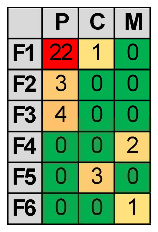
Figure 4.
Recurrences of the pairs functions categories—intervention strategies (P = Preventive, C = Compensative, M = Mitigative). P is the most recurrent intervention strategy, whereas C and M are less frequent. The P-F1 pair is the most frequent for P, whereas C-F5 is the most recurrent for C. F4 and F5 are the functions that recur for M.
The recurrences of behavior categories for each function category are shown in Figure 5, subdivided in terms of intervention strategy. It seems that, for the preventive strategy, B1 is the most recurrent behavior used to implement function F1 (13 out recurrences), while B2, B4, B7, and B9 are less considered. F2 is implemented through B8 and B13. F3 is based mainly on B3 while B11 is less significant. Regarding the compensative intervention, behavior B10 is adopted to implement F1, whereas F5 uses B5. Finally, functions F4 and F6, that implement the mitigative strategy, are based on B6 and B12 respectively.
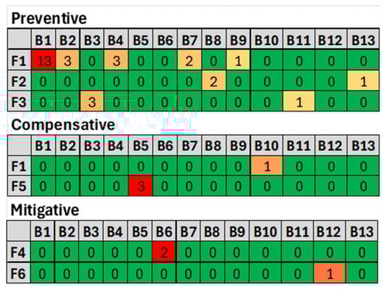
Figure 5.
Recurrences of behaviors categories for each function category, subdivided in terms of intervention strategy. Preventive: B1 is the most recurrent for the implementation of function F1. The behaviors B2, B4, B7 and B9 are less considered. F2 is implemented through B8 and B13, whereas F3 is based on B3 and B11. Compensative: B10 is adopted to implement F1 whereas B5 implements F5. Mitigative: F4 is implemented by B6 and F6 adopts behavior B12.
The occurrences of behavior categories for each structure category are shown in Figure 6, classified by intervention strategy. For the preventive strategy, the pair B1-S1 is the most frequent, appearing 11 times out of 29, while the other pairs are less common. In the compensative strategy, the pair B5-S4 is the most recurrent, with 3 out of 4 occurrences. For the mitigative strategy, the behaviors used to implement it involve structures S6 and S10.
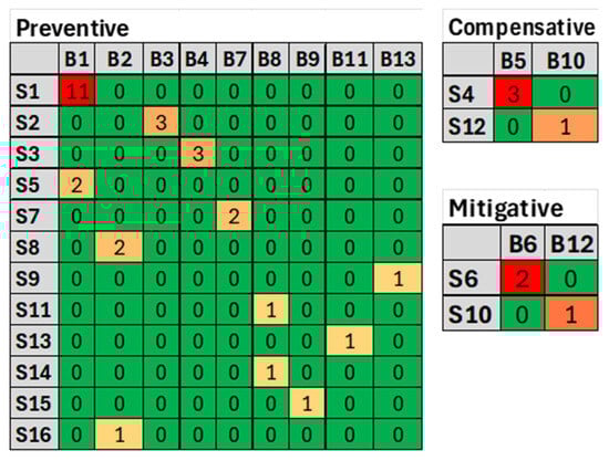
Figure 6.
Recurrences of behaviors categories for each structure category, subdivided by intervention strategy. Preventive: the pair B1-S1 is the most recurrent (11 out of 29), whereas the other pairs are less frequent. Compensative: the pair B5-S4 is the most recurrent (3 out of 4). Mitigative: the behaviors adopted to implement the mitigative strategy uses S6 and S10.
The occurrences of the different intervention strategies in relation to the system levels on which they are applied are shown in Figure 7. As can be observed, the preventive strategy is quite transversal, with solutions found at all levels, although there is a rather marked preference for level L1 (18 occurrences out of 36). On the contrary, the other two strategies seem to be very specific, in fact the compensative strategy works exclusively on level L2, while the mitigative one intervenes only on level L1. In general, levels L1 and L2 are those on which most solutions intervene (29 occurrences out of 36). Moreover, Figure 8 depicts the recurrences of the pair’s behaviors—level of intervention in reference to each intervention strategy. From the analysis of the results regarding preventive strategies, it emerges that B1 is the most considered behavior for solutions that intervene at level L1, and it is the only one used for interventions at levels L4 and L5. B3 is the most recurrent for solutions that operate at level L2, while B4 is the only behavior used by solutions working at level L3. Regarding compensative strategies, solutions adopt B5 and B10 to intervene at level L2. As for mitigative strategies, behaviors B6 and B12 are the only ones employed to intervene at level L1.
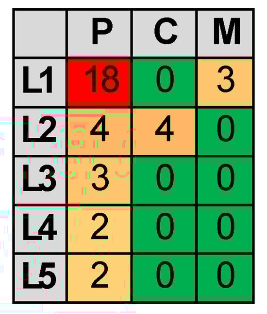
Figure 7.
Recurrences of the interventions strategies according to the different levels of the system on which they act. Overall, P works as a general-purpose strategy, C works on L2, whereas M works on L1. However, most of the intervention strategies that work on level L1 are based on P (18 out of 36), whereas M and C seem to be very specific.
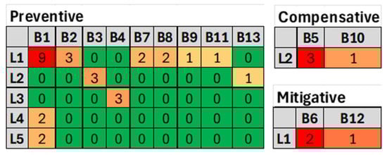
Figure 8.
Recurrences of the pair’s behaviors—level of intervention in reference to each intervention strategy. The analysis shows that B1 is the most common behavior for preventive solutions at level L1 and is uniquely used at levels L4 and L5. B3 is prevalent at level L2, while B4 is specific to level L3. For compensative strategies, B5 and B10 are used at level L2, and for mitigative strategies, B6 and B12 are employed at level L1.
3.3. Summary of Results
The classification model employed to identify relevant solutions provides a comprehensive summary of the results obtained in this study, as illustrated in Figure 9. The chart depicts the recurrence frequency of each solution model, represented according to the quadruple Str-F-B-S. As observed, a total of seventeen solution models recur, with the P-F1-B1-S1-L1 model being the most prevalent, appearing nine times, and demonstrating a significant predominance over the others. The most frequently observed compensative solutions are based on the C-F5-B5-S4-L2 model (three occurrences), whereas the most common mitigative solutions belong to the M-F4-B6-S6-L1 category, with two occurrences.
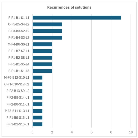
Figure 9.
Recurrences of solutions represented according to the categorization model Str-F-B-S-L.
4. Discussion
The discussion of the results presented in the previous section is organized according to the three intervention strategies underlying the respective solutions. The subsequent analysis provides a detailed examination of the solution models summarized in Figure 9, focusing on their main characteristics.
Regardless of the specific findings, the trend illustrated in Figure 2 indicates that issues related to wear and overheating remain highly significant and continue to represent a fertile area for the development of innovative solutions. It is important to note that, apart from a temporary pause observed in 2020 and the preliminary data for the 2024/2025 period (whose significance cannot yet be fully ascertained at the time of writing), patenting activity has been steadily increasing since 2009.
4.1. Preventive Strategy
Preventive strategy is the most frequently employed among the solutions considered. Consequently, inventive activity has predominantly focused on eliminating or mitigating the underlying causes of wear and overheating. The most utilized approach within solutions adopting this strategy involves reducing friction by transforming sliding friction into rolling friction. Indeed, as evidenced by the collected data, the P-F1 pair is the most prevalent and the reference solution model for the preventive strategy appears to be P-F1-B1-S1-L1, which addresses friction reduction between the contact surfaces of teeth and rollers by inserting rolling elements (of various shapes) within the track between the cycloidal wheel and the fixed wheel. Building on the same concept, solution model P-F1-B1-S1-L5 also uses rolling elements between pins and holes in solutions employing the pin-holes output mechanism. Although highly effective, the implementation of this solution model requires relatively complex structures, involving numerous components and complicating both the kinematic and structural design of the reducer due to the need to embed a great number of bearings, especially between the contact surfaces of cycloidal and fixed wheels.
Interestingly, solutions based solely on lubrication to reduce friction are less frequently considered compared to those employing rolling elements. Indeed, solution models sharing the root configuration P-F1-B2 are implemented with structures that incorporate lubrication circuits within the system to optimally distribute lubricant across the entire contact surface between the cycloidal and fixed wheels (model P-F1-B2-S8-L1). Alternatively, they utilize lubricants with specially formulated chemical compositions (model P-F1-B2-S16-L1), tailored to the high sliding conditions that characterize cycloidal reducer contact. While the first type of solution introduces technological complexity due to the need for containment, pumping, and distribution systems for the lubricant among the components, the second relies solely on the performance of the lubricant itself. In practical applications, therefore, relying exclusively on lubricants can be challenging.
Another class of solutions aimed at reducing friction involves the traditional “pins-holes” mechanism used in cycloidal gear reducers (model P-F1-B4-S3-L3). These solutions are specific to this system and are based on reducing the friction coefficient through the insertion of anti-friction bearings. They are effective and straightforward within such systems, given that the “pins-holes” mechanism significantly impacts efficiency. Moreover, they could be employed even more effectively in conjunction with other solution models.
Less common but still noteworthy are the P-F1-B7-S7-L1 solution models, which propose the adoption of porous contact surfaces between teeth and rollers to imbibe lubricants, ensuring more effective retention and gradual release throughout the reducer’s lifecycle. The main challenge in implementing this type of solution lies in creating porosity in the surface without compromising its load-bearing capacity. Sintering processes are well-established in industrial component manufacturing; however, a primary limitation of this method is the relatively low mechanical strength of the resulting parts. Additionally, managing the degree of porosity is critical, as it influences surface roughness, and in conditions of limited lubrication, excessive porosity could negatively impact the reducer’s efficiency.
Finally, a rare but intriguing configuration based on friction reduction is represented by model P-F1-B9-S15-L1. This involves reducing contact surfaces, combined with the B1 approach of inserting rolling elements between the contact surfaces of the cycloidal wheel and the rollers. The implementation structure (S15) involves a push rod with a bearing at its tip, replacing the traditional cycloidal wheel. This design reduces contact to a single tooth (the tip of the push rod), minimizing sliding surfaces and confining them to a region near the instantaneous center of motion, where sliding speed is very low, thereby drastically reducing friction losses. Although issues regarding functionality and reliability remain still open, the general idea of reducing the number of teeth in contact could serve as an interesting starting point for developing new solutions. However, decreasing the number of contact surfaces increases the contact forces, which could negatively affect contact pressure, thus the balance of these two effects should be carefully investigated to understand the winner.
The study has highlighted solution models that are less intuitively apparent than those based on reducing friction coefficient. Within the framework established by the analysis, a recurring model is P-F3-B3-S2-L2, whose preventive strategy involves increasing the backlash between the components of the gear reducer in relative motion. This approach requires pre-determining the deformation effects resulting from the applied loads during operation to incorporate, during the design phase, tolerances that account for these deformations. Consequently, the actual system will have dimensions differing from the ideal one and will tend to assume its intended shape during operation due to the load generated. This strategy limits deformations to prevent overloads caused by interference between parts due to friction-generated heat. The P-F3-B11-S13-L1 solution model follows the same approach as the previous one but differs in its exclusive focus on the tooth profile, aiming to optimize its shape under operational conditions. Specifically, the design of the contact surface of the teeth is based on the distribution of contact pressure. Therefore, the tooth profile can deform in response to the loading conditions and assume the optimal shape during operation. Although these solution models are highly promising, they necessitate the use of predictive models during the design phase capable of determining how the system will deform under all anticipated effects. Scientific literature offers numerous models capable of predicting the effects caused by contact forces, including wear and overheating. Undoubtedly, their accuracy is a key aspect to consider.
Finally, a category of solutions less common than those discussed above, is based on increasing the resistance of the system elements (P-F2). The implementation of this approach involves two alternative strategies: modifying the physical and chemical properties of the materials through specific thermal treatments applied locally on the contact surfaces (B8) or balancing the contact forces through a more uniform distribution across the entire system (B13). B8 employs a distribution of the contact surface hardness of teeth, that is adjusted according to the contact pressure distribution acting on them (S11 or S14). Conversely, B13 is achieved through a multistage reducer with a predetermined angular offset of the eccentric wheels, aimed at optimizing the distribution and balancing of contact forces (S9). These solution models are highly effective and, conversely, easily designable and implementable compared to those based on F1 and F3, also in consideration of the huge variety and high reliability of the modern processes for thermal treatments.
4.2. Compensative Strategy
Compensative strategies are scarcely employed compared to preventative strategies. Considering the functions through which compensatory solutions operate, it is observed that they are predominantly based on system cooling during operation (F5). Conversely, friction control (F1) is a significantly less considered function, while all other functions are totally absent.
Cooling of the entire system obviously occurs through heat exchange (B5), which is indeed the only behavior associated with this type of solution. This is implemented with structures based on model S4, i.e., through subsystems integrated into the main system, employing pumps, channels traversing system components, heat exchanging parts, and fluids serving as thermal vectors. Clearly, this type of solution model is affected by high complexity, requiring the addition of various components to the main system and necessitating internal channels and surfaces that complicate geometries. Furthermore, the necessity of circulating the carrier fluid leads to a subtraction of useful transmitted power if the pump’s actuation uses motion transmitted from the reducer, or to the addition of a motor for the circulation pump, which in any case requires energy input.
Solutions based on function F1 focus exclusively on the removal of agents that can increase the friction coefficient during operation. Indeed, the behavior B10 used to implement the function is based on the removal of wear scraps generated during operation, which can insert themselves between the contact surfaces of the system’s relatively moving elements, thereby increasing friction and consequently wear and heating. From a structural point of view, the model employed by these solutions adopts magnets positioned inside the system to capture the material scraps (S12). Although these solutions involve the use of magnets, which are still additional system components, they can certainly contribute to hybrid strategies, especially if integrated with preventative ones. However, their major limitation is that they only work for systems built using materials sensitive to magnetic fields, thereby limiting their applicability largely to steels.
Finally, it is observed that the aforementioned solution models operate at level L2, meaning they act on the entire system, demonstrating that compensative strategies are exclusively focused on a global impact.
4.3. Mitigative Strategy
Solution models employing mitigative strategies are predicated upon either backlash recovery functions (F4), addressing degradation phenomena on the contact surfaces between cycloidal gear teeth and their corresponding fixed-wheel rollers, or the restoration of these surfaces’ geometric profiles (F6).
The F4 backlash recovery function is instantiated through the positional adjustment of the degraded surfaces (behavior B6). This is realized via S6-type structural models, characterized by cycloidal and fixed wheels having tapered rather than cylindrical geometries. Consequently, axial adjustment of the wheels facilitates the recovery of backlash that accrues between the contact surfaces due to wear. This solution model utilizes axial adjustment systems based on calibrated shims or threaded nuts, rendering its implementation comparatively straightforward. However, a critical aspect requiring further investigation concerns the impact of wheel conicity on the generation of axial thrust forces upon transmission shafts and, consequently, upon bearings. This effect is inherently contingent upon wear, as the requisite degree of conicity must be predetermined during the design phase based on the system’s anticipated operational conditions. Nevertheless, for minor conicities, the induced axial thrust forces may be negligible and thus readily accommodated by standard bearing configurations.
Solutions based on F6 effect the restoration of the contact surface geometry between the cycloidal gear teeth and the fixed wheel by employing the principle of facilitated component replacement (behavior B12). This principle is embodied in structural designs based on the S10 model, which states the fabrication of cycloidal and fixed wheels as two-piece assemblies: specifically, a disk incorporating a hub for component support, and an external annulus housing the gearing. The inherent ease of axial disassembly facilitates the rapid substitution of these geared annuli, thereby reconstituting the ideal contact surface geometry. This solution model demonstrably offers significant efficacy in restoring system functionality to optimal parameters, contingent upon the genuine simplicity of the various components’ disassemblability.
Considering the preceding discussion, it is evident that solution models implementing the mitigative strategy intervene exclusively at level L1, addressing only those system components encompassing the toothed contact surfaces. In contrast to preventive or compensative strategies, which aim to eliminate or attenuate, respectively, the physical causes and effects that engender thermal generation and material degradation during operational phases (primarily encompassing the coefficient of friction and the resultant thermal energy), mitigative strategies fundamentally disregard these aspects. They confine their intervention exclusively to the restoration of system functionality. Consequently, the system will persist in undergoing thermal accumulation and material degradation without any inherent attenuation. Thus, it is unequivocally clear that mitigative strategies exert negligible influence on enhancing overall system efficiency during the operational lifetime.
4.4. Comparison of the Different Strategies
Overall, the analysis suggests that preventive strategies are paramount for mitigating wear and overheating by addressing root causes, primarily friction reduction. Approaches include converting sliding to rolling friction, though often complex, or utilizing advanced lubrication. Optimizing tooth profiles and backlash also feature, demanding predictive modeling. Conversely, enhancing material resistance through thermal treatments or force distribution provides effective, simpler solutions. Less frequently employed, compensative strategies focus on system cooling or wear debris removal, entailing complexity and potential performance impacts. Mitigative strategies restore degraded surfaces post-wear via adjustable components or replacement. Critically, these do not address root causes, yielding negligible improvement in system operational efficiency.
Therefore, the preventive strategy seems superior as it proactively addresses the underlying causes of wear and overheating, like friction. By eliminating or mitigating problems before they occur, it ensures greater long-term efficiency and system reliability, unlike the reactive compensative or mitigative approaches. While some models are complex, solutions like material hardening are easily designable and implementable and highly effective. This offers robust, root-cause solutions without necessarily prohibitive complexity, unlike the generally complex compensative or limited mitigative approaches.
In conclusion, the choice between these strategies represents a classic engineering trade-off. As shown in Table 5, preventive strategies offer the highest performance and long-term benefit at the cost of upfront design and mechanical complexity. Compensative strategies offer operational control with the penalty of added ancillary systems and energy use. Mitigative strategies offer the lowest initial design complexity and ease of repair but do nothing to improve the system’s fundamental efficiency or longevity, accepting ongoing degradation and parts consumption as a given. The optimal approach likely lies in hybrid models that intelligently combine the strengths of these strategies, such as pairing a robust preventive core with a targeted mitigative service feature, Therefore, an interesting direction for innovation could be the development of solutions that merge the advantages of Preventive and Mitigative strategies and trim disadvantages being these strategies in contrast, while Compensative solutions are scarcely interesting.
Table 5.
Comparison of advantages and disadvantages of the different strategies.
4.5. Suitability for the Industrial Fields
According to the mapped solutions, The Preventive strategy is paramount for high-precision and heavy-duty industries like robotics, aerospace, and advanced manufacturing, where maximizing uptime and operational efficiency is critical. The complexity and cost of integrating rolling elements or advanced lubrication systems are justified in these sectors by the superior performance and longevity gained. The focus on predictive design and material science also makes it highly relevant for the automotive and energy sectors, where reliability under extreme loads is non-negotiable.
The features of solutions based on the Compensative strategy suggest a niche in applications where the core system cannot be easily modified and heat is a primary concern. It is suited for large-scale, stationary industrial machinery or power generation systems where the added complexity, weight, and energy consumption of external cooling circuits can be accommodated. The use of magnetic debris removal is primarily limited to heavy industries using large steel-based machinery.
Eventually, the Mitigative approach is a pragmatic strategy for cost-sensitive and maintenance-oriented industries like conventional automotive, agricultural machinery, or material handling. Its simplicity and ease of repair align with sectors where operational efficiency is less critical than minimizing downtime and repair costs. This approach is ideal for applications where reducers are easily accessible for service and where accepting gradual degradation in exchange for lower initial investment is a viable trade-off.
5. Conclusions
This study provides a comprehensive analysis of patent-based solutions for wear and thermal management in cycloidal reducers, offering valuable insights into current technological trends and intervention strategies. The adopted classification model has general validity and can be applied to other gear systems as its core components are abstract and universal, not specific to cycloidal drives. Therefore, this model provides a powerful, standardized lexicon for analyzing, comparing, and innovating solutions across any gear system.
The findings reveal that preventive strategies, particularly those focused on friction reduction through rolling elements, dominate the landscape, highlighting their effectiveness in addressing root causes of wear and overheating. Compensative strategies, though less prevalent, emphasize cooling systems and wear debris removal, while mitigative approaches primarily restore functionality post-degradation without tackling underlying issues. The predominance of preventive solutions underscores their superiority in enhancing long-term efficiency and reliability, despite some implementation complexities. Notably, material resistance enhancements and optimized tooth profiles present simpler yet effective alternatives. The study also identifies gaps, such as the limited exploration of mitigative strategies and the need for hybrid solutions combining multiple approaches. These insights not only consolidate existing knowledge but also pave the way for future innovations, encouraging further research into predictive modeling, advanced materials, and integrated systems. By mapping the state-of-the-art, this work serves as a foundational reference for engineers and researchers aiming to develop next-generation cycloidal reducers with improved performance and durability.
Funding
This research received no external funding.
Conflicts of Interest
The authors declare no conflicts of interest.
Abbreviations
The following abbreviations are used in this manuscript:
| CFD | Computational Fluid Dynamics |
| FBS | Function Behavior Structure |
Appendix A
| Item | Ref. | Inventors | Title | Publication Numbers | Priority Dates |
| 1 | [15] | Yu Wancheng | Cycloid speed reducer oil temperature over-high alarm device | CN211039636 | 5 December 2019 |
| 2 | [16] | Zhou Haimin | Cycloidal speed reducer | CN221374400 | 27 July 2023 |
| 3 | [17] | Chen Weifang | Horizontal type cycloidal speed reducer lubricating agent composition | CN106433865 | 5 September 2016 |
| 4 | [18] | Kwon Soon Man Kim Chang Hyun Nam Hyoungchul | Wear reduction cycloidal speed reducer using roller gear mechanism | KR10-1422411 | 17 June 2013 |
| 5 | [19] | Shi Zhengze Cen Kai Ye Huaping Chen Chunhua | Large-bearing-capacity radial ball cycloid speed reducer device | CN117249209 | 6 November 2023 |
| 6 | [20] | Wang Guodong | Cycloidal speed reducer with single end face contact pushing rod | CN2199370 | 7 May 1994 |
| 7 | [21] | Guo Shuang Xu Jiakui Liu Cheng Li Wan Zhou Dan Zhong Chengbao Cheng Zhongfu Sun Bao | Cycloidal gear and speed reducer | CN109404497 JP7203966 JP2022508033 WO2020/107983 CN109404497 | 26 November 2018 2 September 2019 |
| 8 | [22] | Li Abo Li Xiang Tian Guangze | Superfinishing method of cycloidal gear | CN108161377 CN108161377 | 27 December 2016 |
| 9 | [23] | Qu Shengguan Wang Jintao Shao Huitu Li Xiaoqiang Geng Jianwei Deng Yunqing | RV reducer cycloidal gear profile modification method based on temperature effect | CN114692405 CN114692405 | 25 March 2022 |
| 10 | [24] | Chen Han | Cycloidal gear reducer | CN110285198 | 23 July 2019 |
| 11 | [25] | Liang Guangsheng Hu Yusheng Zhong Chengbao Cui Zhong cheng zhongfu Liu Cheng Sun Bao Tian Zhenzhen | Cycloidal gear, reducer and robot | WO2020/056962 CN109139861 | 19 September 2018 |
| 12 | [26] | Xiao zhiding Pan Yuliang Yang Yicheng Peng Xiangnan Peng Shihua | Cycloidal gear, RV speed reducer and robot | CN118959568 | 22 August 2024 |
| 13 | [27] | Braedt Henrik Heyna Sebastian | Cycloidal transmission and electric bicycle drive unit with cycloidal transmission | DE102024115659 | 21 June 2023 22 June 2023 |
| 14 | [28] | She Jianglin | Cycloidal gear and RV speed reducer | CN116336070 CN116336163 CN115823191 | 23 September 2022 |
| 15 | [29] | Tang Jianliu Ye Huaping | Cycloidal transmission mechanism of speed reducer based on rolling cone piece | CN107165986 CN107165986 | 16 June 2017 |
| 16 | [30] | Jiang Jianbang Chen Kun Huang Xingpan Jiang Yachun Han Shijun Lin Shutong | Buffering speed-reducing cycloidal gear | CN219734140 | 13 April 2023 |
| 17 | [31] | Zhang Qqianhu Wang Libo | Cycloidal gear and RV speed reducer | CN217814794 | 10 August 2022 |
| 18 | [32] | Tang Jianliu Ye Huaping | Speed reducer cycloid transmission mechanism based on drum-shaped ball piece | CN107143622 CN107143622 | 28 June 2017 |
| 19 | [33] | Du Xuesong Zhu Feihong Zhu Caichao Jing Yan Hu Rui | Adjustable variable tooth thickness cycloidal pin gear transmission device | CN108533695 CN108533695 | 6 July 2018 |
| 20 | [34] | Wan Zhen Wang Shuhong | Gear structure of cycloidal-pin gear speed reducer | CN210686871 | 14 August 2019 |
| 21 | [35] | Bao Junhua Peng Darui He Weidong | Cycloid steel ball transmission bearing speed reducer with pinwheel output | CN214274364 | 22 December 2020 |
| 22 | [36] | Bu Wanghui Li Jia | Method for modifying cycloid pin gear transmission device and cycloid pin gear transmission device | CN106523599 CN106523599 | 20 December 2016 |
| 23 | [37] | Ren Rongfu Wang Mingwei Chen Weijun Liu Jiangyuan Ren Zezheng | High-stability RV reducer and detection method thereof | CN115750691 CN115750691 | 16 December 2022 |
| 24 | [38] | Liu Weiwei | Reducer for high precision control | CN116717568 US11644085 US20220074466 WO2020/233193 CN110966357 | 22 May 2019 31 December 2019 6 March 2020 |
| 25 | [39] | Liu Weiwei | Hollow reducer for high precision control | CN118912161 US11692614 US20220074467 WO2020/233194 CN110985611 | 22 May 2019 31 December 2019 6 March 2020 |
| 26 | [40] | Wu Shengzhen | Cycloid reduction gearbox of interlayer air cooling box zinc base alloy bearing support | CN104196988 | 6 August 2014 |
| 27 | [41] | Liu Weiwei | Internal meshing speed reducer for precision control | CN116972116 WO2020/233195 CN111059225 | 22 May 2019 31 December 2019 |
| 28 | [42] | Shi Zhengze Cen Kai Ye Huaping Chen Zhiyu | Large-bearing-capacity radial two-stage parallel inner and outer cycloid oscillating tooth speed reduction and transmission device | CN117662689 | 6 November 2023 |
| 29 | [43] | Li Wen Chia Liu Chia Min Cheng Hsu Min Liou Yu Cheng | Cycloid reducer with a roller retaining structure | KR10-2235948 | 31 January 2020 |
| 30 | [44] | Liu Yi-cheng Huang Chao-min | High reduction ratio reducer | TW202118953 TWI704305 | 1 November 2019 |
| 31 | [45] | Tu Zhiwei Ding Shengsong | Poor high accuracy cycloid gear reduction unit of few tooth | CN204755770 | 24 June 2015 |
| 32 | [46] | Wu Shengzhen | Cycloid yawing gearbox of wind driven generator | CN103032524 CN103032524 | 1 October 2011 |
| 33 | [47] | Wu Shengzhen | Cycloid pitch-variable gearbox for wind driven generator | CN103032522 | 1 October 2011 |
| 34 | [48] | Guo Tong Li Xinming Huang Xiaomin Que Fumin Feng Zhike Lin Tianliang | Novel four-phase RV speed reducer and working method thereof | CN119267529 | 28 October 2024 |
| 35 | [49] | Wang Fei Ding Liang Yu Zhenzhong Chen Huan Zhang Jiejie Zhao Fuchen Li Luyang Wang Jian | Accurate cycloidal pin wheel speed reducer of toper needle tooth | CN207864538 | 28 December 2017 |
| 36 | [50] | Tang Jianliu Ye Huaping Ni Jiansheng | Robot reduction box based on oval balls and robot | CN107299969 | 13 July 2017 |
References
- García, P.L.; Crispel, S.; Saerens, E.; Verstraten, T.; Lefeber, D. Compact Gearboxes for Modern Robotics: A Review. Front. Robot. AI 2020, 7, 103. [Google Scholar] [CrossRef] [PubMed]
- Pham, A.; Ahn, H. Rigid precision reducers for machining industrial robots. Int. J. Precis. Eng. Man. 2021, 22, 1469–1486. [Google Scholar] [CrossRef]
- Allotta, B.; Fiorineschi, L.; Maccioni, L.; Papini, S.; Pugi, L.; Rindi, A.; Rotini, F. Design of a Wolfrom cycloidal gearbox made with polymeric materials for mass production on smart construction yards. Int. J. Mech. Control. 2020, 21, 129–142. [Google Scholar]
- Maccioni, L.; Concli, F. Computational Fluid Dynamics Applied to Lubricated Mechanical Components: Review of the Approaches to Simulate Gears, Bearings, and Pumps. Appl. Sci. 2020, 10, 8810. [Google Scholar] [CrossRef]
- Li, X.; Yang, H.; Niu, W.; Guo, R.; Sun, L. Investigation on Tooth Surface Wear of Cycloid Drives Considering Tooth Profile Modifications. Lubricants 2023, 11, 323. [Google Scholar] [CrossRef]
- Wang, Y.; Wei, B.; Wang, Z.; Yang, J.; Xu, J. Research on Loaded Contact Analysis and Tooth Wear Calculation Method of Cycloid–Pin Gear Reducer. Lubricants 2023, 11, 445. [Google Scholar] [CrossRef]
- Vasić, M.; Blagojević, M.; Banić, M.; Maccioni, L.; Concli, F. Theoretical and Experimental Investigation of the Thermal Stability of a Cycloid Speed Reducer. Lubricants 2025, 13, 70. [Google Scholar] [CrossRef]
- Guglielmi, P.; Davoodi, F.; Palumbo, G.; Carbone, G. Tribological behaviour of microindented 100Cr6 steel surfaces in dry contact conditions. Int. J. Adv. Manuf. Technol. 2024, 133, 2381–2400. [Google Scholar] [CrossRef]
- Webb, A. TRIZ: An Inventive Approach to Invention. EMJ-Eng. Manag. J. 2012, 12, 171–177. [Google Scholar] [CrossRef]
- Fiorineschi, L.; Frillici, F.S.; Rotini, F. Enhancing Functional Decomposition and Morphology with TRIZ: A Literature Review. Comput. Ind. 2018, 94, 1–15. [Google Scholar] [CrossRef]
- Fiorineschi, L.; Frillici, F.S.; Rotini, F. Re-design the design task through triz tools. In Proceedings of the 14th International Design Conference, Dubrovnik, Croatia, 16–19 May 2016. [Google Scholar]
- Fiorineschi, L.; Rissone, P.; Rotini, F. A new conceptual design approach for overcoming the flaws of functional decomposition and morphology. J. Eng. Des. 2016, 27, 438–468. [Google Scholar] [CrossRef]
- Pahl, G.; Beitz, W. Engineering Design—A Systematic Approach, 3rd ed.; Springer: London, UK, 2007; p. 617. [Google Scholar]
- Gero, J.S.; Kannengiesser, U. The situated function-behaviour-structure framework. Des. Stud. 2004, 25, 373–391. [Google Scholar] [CrossRef]
- Yu, W. Cycloid Speed Reducer Oil Temperature Over-High Alarm Device. CN211039636, 5 December 2019. [Google Scholar]
- Zhou, H. Cycloidal Speed Reducer. CN221374400, 27 July 2023. [Google Scholar]
- Chen, W. Horizontal Type Cycloidal Speed Reducer Lubricating Agent Composition. CN106433865, 5 September 2016. [Google Scholar]
- Kwon, S.M.; Kim, C.H.; Nam, H. Wear Reduction Cycloidal Speed Reducer Using Roller Gear Mechanism. KR10-1422411, 17 June 2013. [Google Scholar]
- Shi, Z.; Cen, K.; Ye, H. Chen, C. Large-Bearing-Capacity Radial Ball Cycloid Speed Reducer Device. CN117249209, 6 November 2023. [Google Scholar]
- Wang, G. Cycloidal Speed Reducer with Single End Face Contact Pushing Rod. CN2199370, 7 May 1994. [Google Scholar]
- Guo, S.; Xu, J.; Liu, C.; Li, W.; Zhou, D.; Zhong, C.; Cheng, Z.; Sun, B. Cycloidal Gear and Speed Reducer. CN109404497, 26 November 2018. [Google Scholar]
- Li, A.; Li, X.; Tian, G. Superfinishing Method of Cycloidal Gear. CN108161377, 27 December 2016. [Google Scholar]
- Qu, S.; Wang, J.; Shao, H.; Li, X.; Geng, J.; Deng, Y. RV Reducer Cycloidal Gear Profile Modification Method Based on Temperature Effect. CN114692405, 25 March 2022. [Google Scholar]
- Chen, H. Cycloidal Gear Reducer. CN110285198, 23 July 2019. [Google Scholar]
- Liang, G.; Hu, Y.; Zhong, C.; Cui, Z.; Cheng, Z.; Liu, C.; Sun, B.; Tian, Z. Cycloidal Gear, Reducer and Robot. CN109139861, 19 September 2018. [Google Scholar]
- Xiao, Z.; Pan, Y.; Yang, Y.; Peng, X.; Peng, S. Cycloidal gear, RV Speed Reducer and Robot. CN118959568, 22 August 2024. [Google Scholar]
- Henrik, B.; Sebastian, H. Cycloidal Transmission and Electric Bicycle Drive Unit with Cycloidal Transmission. DE102024115659, 21 June 2023. [Google Scholar]
- She, J. Cycloidal Gear and RV Speed Reducer. CN116336070, 23 September 2022. [Google Scholar]
- Tang, J.; Ye, H. Cycloidal Transmission Mechanism of Speed Reducer Based on Rolling Cone Piece. CN107165986, 16 June 2017. [Google Scholar]
- Jiang, J.; Chen, K.; Huang, X.; Jiang, Y.; Han, S.; Lin, S. Buffering Speed-Reducing Cycloidal Gear. CN219734140, 13 April 2023. [Google Scholar]
- Zhang, Q.; Wang, L. Cycloidal Gear and RV Speed Reducer. CN217814794, 10 August 2022. [Google Scholar]
- Tang, J.; Ye, H. Speed Reducer Cycloid Transmission Mechanism Based on Drum-Shaped Ball Piece. CN107143622, 28 June 2017. [Google Scholar]
- Du, X.; Zhu, F.; Zhu, C.; Jing, Y.; Hu, R. Adjustable Variable Tooth Thickness Cycloidal Pin Gear Transmission Device. CN108533695, 6 July 2018. [Google Scholar]
- Wan, Z.; Wang, S. Gear Structure of Cycloidal-Pin Gear Speed Reducer. CN210686871, 14 August 2019. [Google Scholar]
- Bao, J.; Peng, D.; He, W. Cycloid Steel Ball Transmission Bearing Speed Reducer with Pinwheel Output. CN214274364, 22 December 2020. [Google Scholar]
- Bu, W.; Li, J. Method for Modifying Cycloid Pin Gear Transmission Device and Cycloid Pin Gear Transmission Device. CN106523599, 20 December 2016. [Google Scholar]
- Ren, R.; Wang, M.; Chen, W.; Liu, J.; Ren, Z. High-Stability RV Reducer and Detection Method Thereof. CN115750691, 16 December 2022. [Google Scholar]
- Liu, W. Reducer for High Precision Control. CN110966357, 22 May 2019. [Google Scholar]
- Liu, W. Hollow Reducer for High Precision Control. CN110985611, 22 May 2019. [Google Scholar]
- Wu, S. Cycloid Reduction Gearbox of Interlayer Air Cooling Box Zinc Base Alloy Bearing Support. CN104196988, 6 August 2014. [Google Scholar]
- Liu, W. Internal Meshing Speed Reducer For Precision Control. CN111059225, 22 May 2019. [Google Scholar]
- Shi, Z.; Cen, K.; Ye, H.; Chen, Z. Large-Bearing-Capacity Radial Two-Stage Parallel Inner and Outer Cycloid Oscillating Tooth Speed Reduction and Transmission Device. CN117662689, 6 November 2023. [Google Scholar]
- Li, W.C.; Liu, C.M.; Cheng, H.M.; Liou, Y.C. Cycloid Reducer with a Roller Retaining Structure. KR10-2235948, 31 January 2020. [Google Scholar]
- Liu, Y.-c.; Huang, C.-m. High Reduction Ratio Reducer. TW202118953, 1 November 2019. [Google Scholar]
- Tu, Z.; Ding, S. Poor High Accuracy Cycloid Gear Reduction Unit of Few Tooth. CN204755770, 24 June 2015. [Google Scholar]
- Wu, S. Cycloid Yawing Gearbox of Wind Driven Generator. CN103032524, 1 October 2011. [Google Scholar]
- Wu, S. Cycloid Pitch-Variable Gearbox for Wind Driven Generator. CN103032522, 1 October 2011. [Google Scholar]
- Guo, T.; Li, X.; Huang, X.; Que, F.; Feng, Z.; Lin, T. Novel Four-Phase Rv Speed Reducer and Working Method Thereof. CN119267529, 28 October 2024. [Google Scholar]
- Wang, F.; Ding, L.; Yu, Z.; Chen, H.; Zhang, J.; Zhao, F.; Li, L.; Wang, J. Accurate Cycloidal Pin Wheel Speed Reducer of Toper Needle Tooth. CN207864538, 28 December 2017. [Google Scholar]
- Tang, J.; Ye, H.; Ni, J. Robot Reduction Box Based on Oval Balls and Robot. CN107299969, 13 July 2017. [Google Scholar]
Disclaimer/Publisher’s Note: The statements, opinions and data contained in all publications are solely those of the individual author(s) and contributor(s) and not of MDPI and/or the editor(s). MDPI and/or the editor(s) disclaim responsibility for any injury to people or property resulting from any ideas, methods, instructions or products referred to in the content. |
© 2025 by the authors. Licensee MDPI, Basel, Switzerland. This article is an open access article distributed under the terms and conditions of the Creative Commons Attribution (CC BY) license (https://creativecommons.org/licenses/by/4.0/).