Article

Biomimetic Hexagonal Texture with Dual-Orientation Groove Interconnectivity Enhances Lubrication and Tribological Performance of Gear Tooth Surfaces

1
School of Marine Equipment and Mechanical Engineering, Jimei University, Xiamen 361021, China
2
National Gear Product Quality Inspection and Testing Center, China Academy of Machinery Zhengzhou Research Institute of Mechanical Engineering Co., Ltd., Zhengzhou 450001, China
*
Author to whom correspondence should be addressed.
Lubricants 2025, 13(9), 420; https://doi.org/10.3390/lubricants13090420
Submission received: 18 August 2025 / Revised: 6 September 2025 / Accepted: 16 September 2025 / Published: 18 September 2025

Abstract

Enhanced lubrication is critical for improving gear wear resistance. Current research on surface textures has overlooked the fundamental role of structural connectivity. Inspired by biological scales, a biomimetic hexagonal texture (BHT) was innovatively designed for tooth flanks, featuring dual-orientation grooves (perpendicular and inclined to the rolling-sliding direction) with bidirectional interconnectivity. This design synergistically combines hydrodynamic effects and directional lubrication to achieve tribological breakthroughs. A lubrication model for line contact conditions was established. Subsequently, the texture parameters were then optimized using response surface methodology and numerical simulations. FZG gear tests demonstrated the superior performance of the optimized BHT, which achieved a substantial 82.83% reduction in the average wear area ratio and a 25.35% decrease in tooth profile deviation variation. This indicated that the biomimetic texture can effectively mitigate tooth surface wear, thereby extending the service life of gears. Furthermore, it significantly improves thermal management by enhancing convective heat transfer and lubricant distribution, as evidenced by a 7–11 °C rise in bulk lubricant temperature. This work elucidates the dual-mechanism coupling effect of bio-inspired textures in tribological enhancement, thus establishing a new paradigm for gear surface engineering.

1. Introduction

Gears, as the core components of mechanical transmission systems, are widely used in wind power generation, rail transportation, and aerospace fields due to their high efficiency, high precision, and high reliability [1,2]. However, gear surface wear and scuffing failure are particularly prominent issues in engineering practice, which severely limits the stability and service life of gear transmission systems [3]. Studies have shown that direct tooth surface contact and oil film rupture are the core causes of such failures [4,5]. Therefore, to improve the lubrication conditions in the gear contact zone, exploring advanced lubrication control technologies is considered a crucial direction for developing high-performance gear transmission systems.
Surface texturing technology has attracted much attention because of its unique mechanism for lubrication and friction modulation [6,7,8]. This technology involves preparing arrays of micro-pits and grooves on contact surfaces through various advanced manufacturing methods (e.g., laser surface processing, electrolytic etching processing, and ultrasonic-assisted vibration processing) to enhance the tribological properties of moving pairs [9]. The tribological benefits primarily stem from three fundamental mechanisms: (1) serving as micro-reservoirs for lubricant storage under starved conditions [10,11], (2) trapping wear debris to reduce three-body abrasion [12], and (3) enhancing hydrodynamic pressure generation to improve load-carrying capacity [13,14]. To date, textured surfaces have demonstrated substantial reductions in friction and wear, as well as noise reduction effects, in conformal contact key tribological components such as bearings [15], piston ring-cylinder liner systems [16,17], and mechanical seals [18].
Gear transmission involves both rolling and sliding contacts, exhibiting typical non-conformal contact characteristics that pose significant challenges for surface texture design [19]. The structural and distribution parameters of textures (e.g., shape, size, and arrangement) significantly influence lubrication performance [20]. Isotropic textures (e.g., uniformly distributed pit arrays) aid in lubricant storage but often lack directional control capabilities; anisotropic textures (e.g., directional grooves) can transport lubricant along specific paths but may also lead to lubricant leakage issues [21]. Currently, gear surface texture applications remain in their infancy, primarily focused on single-scale discrete textures, such as arrays containing only pits or grooves [22,23,24,25,26]. However, existing research indicates that multi-scale textures can integrate multiple functions onto a single surface, thereby more effectively enhancing tribological performance [27]. For instance, Zhu [28] et al. compared single-scale and multi-scale textures through wear experiments and found that multi-scale textures achieved lower coefficients of friction. Building on this, this study proposed an innovative concept: designing a surface texture that combines directed lubricant control capabilities with hydrodynamic lubrication performance to enhance gear surface wear resistance.
In recent years, bio-inspired surface texture design has emerged as a burgeoning research field, providing innovative solutions to combat surface wear [29,30]. In nature, numerous biological surfaces exhibit spatially continuous hexagonal patterns, with exemplary manifestations in snake and lizard scales [31], honeycomb structures [32], and frog toe pads [33]. Such configurations maintain structural continuity along two mutually orthogonal directions. Crucially, studies have demonstrated that the unique hexagonal groove topology between snake and lizard scales significantly reduces frictional resistance during motion, thereby conferring exceptional wear resistance [34,35]. Furthermore, research by Zhong et al. [36] has established that under sliding contact conditions, hexagonal textures can substantially enhance oil film load-carrying capacity while reducing the coefficient of friction. Collectively, these findings underscore the significant potential of hexagonal lattice patterns as biomimetic morphologies for improving lubrication and mitigating surface wear.
Therefore, inspired by natural paradigms, this study innovatively proposed a biomimetic hexagonal texture (BHT) with dual-orientation groove interconnectivity. This design offered two key advantages over conventional surface textures. Firstly, unlike traditional pit or groove structures that mainly acted as lubricant reservoirs, the BHT not only provided oil storage but also enabled directional control over lubricant flow, thus resulting in significantly improved lubricant distribution [37]. Secondly, while cross-hatched patterns can directionally regulate lubricant movement, they often lack grooves perpendicular to the motion direction, which are essential for effective hydrodynamic pressure buildup. In contrast, the BHT incorporated strategically oriented perpendicular grooves that enhanced hydrodynamic pressure generation while maintaining well-controlled lubricant distribution [38].
The precise quantification of gear wear was critical for assessing surface durability and performance. Standard techniques for wear evaluation included optical microscopy [39], scanning electron microscopy (SEM) [40], and contact profilometry [41]. Optical microscopy enabled rapid, nondestructive surface examination but was often limited by reflective artifacts and insufficient resolution for fine wear details. SEM provided high-resolution imaging and detailed topographic analysis, enabling the detection of subtle wear mechanisms such as micro-pitting and abrasion, though it required precise sample preparation and could not perform in-situ measurements. Contact profilometry provided precise depth and roughness data but involves physical contact with the surface, potentially causing further damage to worn components. Recently, innovative alternatives like touch gel sensors have emerged to address these limitations. These sensors captured high-fidelity surface impressions nondestructively and were particularly effective for complex geometries or under low-light conditions where optical techniques were inadequate. For example, this method has been successfully used to document wear patterns on archaeological artifacts, demonstrating its value for sensitive and irregular surfaces [42]. Nevertheless, in current gear wear research, the combination of non-contact optical methods and high-resolution SEM remained the predominant approach for comprehensive analysis, as it integrated macroscopic morphology with microscopic mechanism characterization to explain wear mechanisms.
This study systematically investigated the tribological properties of BHT through a three-phase framework. First, twin-disc tests simulating gear meshing conditions validated the engineering applicability and efficacy of the textures. Subsequently, a dynamic lubricated contact model for gear meshing zones was established integrated with response surface methodology (RSM), through which the influence mechanisms of key geometric texture parameters on oil film pressure fields were elucidated to achieve global parameter optimization. Finally, wear tests conducted on standardized FZG gear testing enabled multidimensional quantitative evaluation of wear resistance performance in textured gear pairs. The research architecture is illustrated in Figure 1.

2. Design and Tribological Property of Biomimetic Texture

2.1. Texture Design

American snakes (Loxocemus bicolor) and Xinjiang rock lizards (Laudakia stoliczkana Blanford) live in rocky areas, and the grooves between their scales exhibit a regular hexagonal geometry that effectively reduces wear on their scales [34,35], as shown in Figure 2a.
The biomimetic hexagonal texture (BHT) is defined by two groove types: those perpendicular to and those inclined to the tooth flank rolling-sliding direction. As shown in Figure 2b, bidirectional interconnectivity is enabled in BHT by its composite grooves. To simplify geometric constraints and ensure dimensional consistency, the aspect ratio λ (defined as a/b, where a and b represent the major and minor axes, respectively) is set equivalent to that of an ortho-hexagonal configuration.
λ = a b = 2 3
The width and depth of the groove are denoted as w and h, respectively. Angle θ represents the included angle between the major axis and the inclined groove. Since λ is a constant, the bio-inspired hexagonal texture transforms into a rhombic pattern at θ = 40.89°, and becomes rectangular at θ = 90°.

2.2. Tribological Test

Given the substantial cost and time requirements of gear wear testing, researchers increasingly employ twin-disc simulation to replicate gear meshing conditions of rolling-sliding line contact [24,43]. Hence, this paper first verifies the effectiveness of the BHT through twin-disc testing.

2.2.1. Experimental Configuration

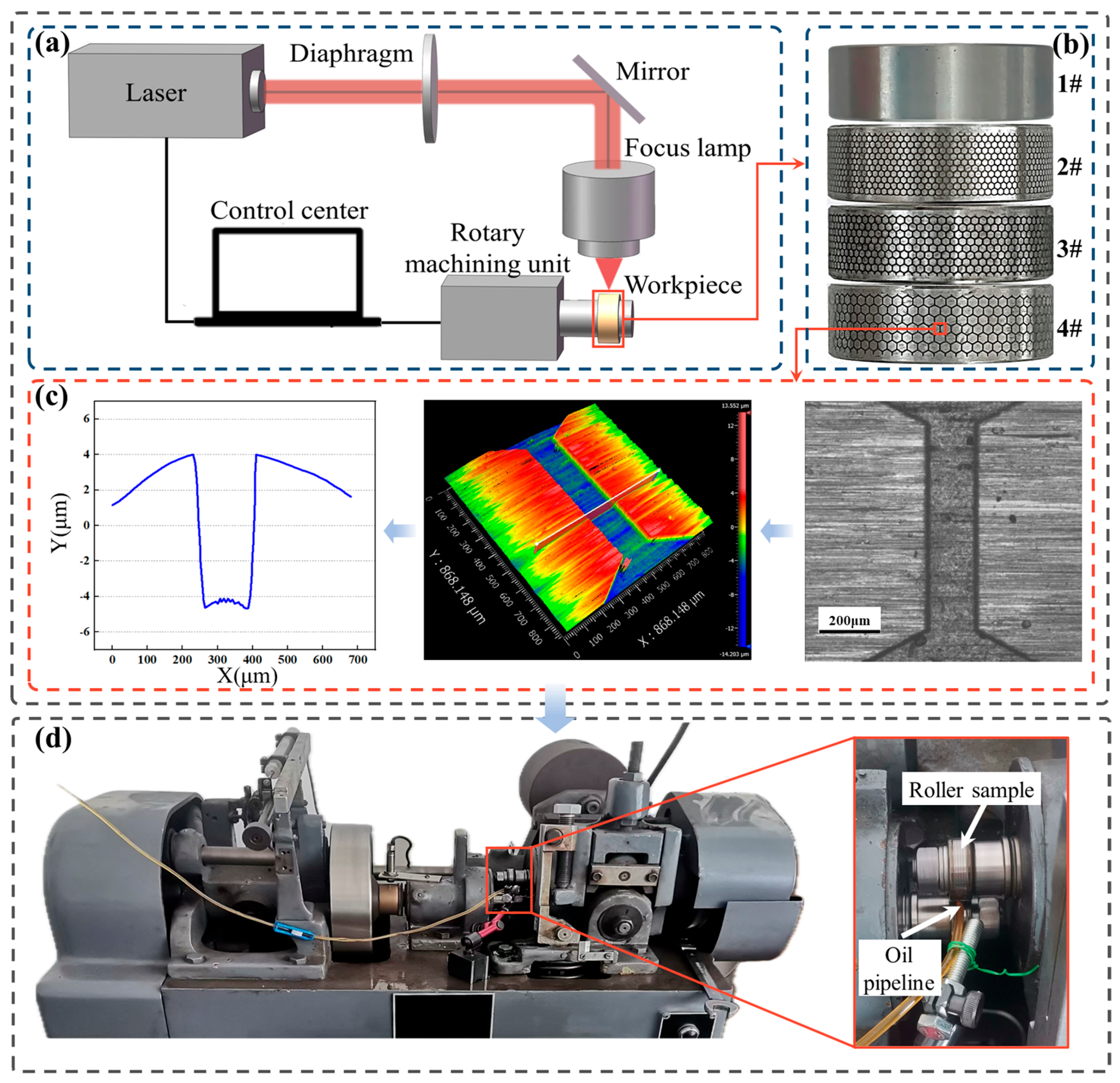
20MnCr5 is a common alloy steel that, after carburizing treatment, combines extremely high surface hardness with good core toughness. It is therefore widely used in the manufacture of gears for automotive and industrial gearboxes [44]. According to the standard (DIN EN 10084), the chemical composition of the material was summarized in Table 1. Test specimens consisted of 30 mm and 40 mm outer diameter rollers featuring 16 mm inner diameter bores. The specimens included one pair of untextured rollers (1#) and three pairs of BHT rollers (2#, 3#, and 4#). The BHT specimens (2#, 3#, and 4#) feature minor axis dimensions of 350 μm, 450 μm, and 550 μm, respectively. All remaining parameters remained fixed per previous research [24], with width measuring 140 μm, depth 10 μm, and angle 60°. The textured specimen was processed by a Picosecond Laser Cepheus instrument (Photon Energy, Nuremberg, Bavaria, DE, Germany) as shown in Figure 3a,b. The surface morphology of the textured rollers was obtained with the 3D Optical Surface Profiler New View 9000 instrument (ZYGO, Stamford, CT, USA), as shown in Figure 3c.
The Wear Testing Machine MMS-2A instrument (Jingcheng, Jinan, China) was used for friction and wear experiments to simulate the rolling-sliding line contact conditions in gearing processes, as shown in Figure 3d. The lubricant used was L-CKC No. 68 medium-load gear oil, with a density (ρ) of 850 kg/m3 and a viscosity (μ) of 0.05797 kg/(m·s). The tests were carried out under a torque of 5 N·m, a test force of 1800 N, a small cylindrical roller speed of 400 r/min, a large cylindrical roller speed of 360 r/min, a slip-roll ratio of 0.182, and a test duration of 30 min. To minimize the influence of environmental factors, each cylindrical roller group underwent three friction tests. And the coefficient of friction (COF) as the main evaluation criteria.

2.2.2. Experimental Result

The experiment results of the group of rollers friction characteristics are shown in Figure 4. The trend of COF with time is consistent, and the COF of the BHT specimens is significantly lower than that of the untextured specimen, as shown in Figure 4a. Among them, the COF of the BHT specimen (3#) is the lowest, with an average friction coefficient of 0.180, which is a 9.55% reduction compared to the untextured (1#), as shown in Figure 4b. Similarly, the wear amount of all the BHT specimens is lower than that of the untextured rollers, and the specimen (3#) has the lowest wear amount, which is a 53.24% reduction compared to the untextured (1#), as shown in Figure 4b. The above results show that the BHT showed good tribological properties under rolling-sliding line contact conditions. This may be due to the BHT-controlled oil film pressure, which improves the lubrication of the specimen surface and thus reduces the wear amount of the surface.
Figure 5 shows the surface wear morphology of each group of post-test rollers obtained with the Scanning Electron Microscope Phenom XL instrument (Phenom, Eindhoven, North Brabant, The Netherlands). The surface of the untextured roller has obvious plough furrow phenomena formed by localized metal detachment and severe wear. Comparing the SEM images of the untextured and BHT specimens, it can be found that the surface damage size of the BHT specimens is smaller, and the wear is significantly reduced compared to the untextured specimen. Moreover, the surface of the BHT specimen (3#) with a minor axis b of 450 μm has no obvious wear and has the most complete morphology.

3. Parameters Optimization of BHT

To investigate the influence of BHT texture parameters on lubrication performance and identify the optimal texture parameters for lubrication, this study followed the optimization process as shown in Figure 6. This process primarily consists of three stages: In stage 1, a hydrodynamic lubrication simulation model for BHT texture was established based on the continuity equation and Navier-Stokes equations, with boundary conditions set according to the actual operating conditions of the twin-disc test. Stage 2 employed single-factor analysis, using load-carrying capacity, coefficient of friction, and hydrodynamic performance as evaluation metrics to systematically analyze the influence of each texture parameter on hydrodynamic lubrication behavior, thereby preliminarily determining an optimal parameter range. Stage 3 adopted a central composite design (CCD) method to formulate an optimization experimental plan, with hydrodynamic performance as the response objective, ultimately identifying the optimal texture parameter combination.

3.1. Simulation Models

The BHT demonstrates effective performance in wear reduction under rolling-sliding line contact conditions, which may be related to the geometric dimensions and bidirectional interconnectivity characteristics of BHT. In this paper, the roller-to-roller model is simplified to an equivalent lubrication model consisting of a rigid cylinder and a flat surface [24], as shown in Figure 7. Here, the upper wall surface of the model is a cylindrical surface with a radius R equal to the equivalent radius of curvature of the large and small rollers, measuring 8.5714 mm. The depth of the grooves h and the minimum oil film thickness h0 are defined.
The fluid flow behavior is governed by the Navier-Stokes equations and the continuity equation, which describe the conservation of momentum and mass for the lubricant flow, respectively [13]:
ρ t + ρ u = 0
ρ u t + ρ u u = p + η 2 u
In the above equation, ρ denotes the density, t denotes the time, u denotes the velocity vector, p denotes the pressure on the fluid element, and ƞ is the kinetic viscosity of the lubricant.
The boundary conditions of the simulation model are shown in Figure 7a,c. (1) The upper boundary is prescribed with counterclockwise rotational motion (ω = 87.97 rad/s), while the lower boundary maintained rightward translational motion (u0 = 0.628 m/s); (2) the differential pressure between the inlet and outlet of the fluid domain is negligible and is treated as a periodic cyclic boundary to simulate the real flows; and (3) the Schnerr-Sauer cavitation model was employed to characterize lubricant cavitation phenomena under actual operating conditions. And a coupled solution algorithm is adopted to precisely resolve the flow dynamics in the textured lubrication system.
The average load-carrying capacity per unit area F* and the average friction force per unit area f* are two key performance indicators used to quantitatively evaluate the hydrodynamic lubrication behavior of the textured surface. These parameters can be calculated as follows:
F * = 0 L 1 0 L 2 P d x d y L 1 L 2
f * = 0 L 1 0 L 2 τ d x d y L 1 L 2
where P is the oil film pressure of the fluid lubricant in Pa, L1 and L2 are the length and width of the cell texture in m2, and τ is the shear stress of the fluid lubricant in Pa.
The coefficient of friction f is calculated from the ratio of the average friction force to the average load-carrying capacity. Meanwhile, the hydrodynamic performance factor K serves as an indicator of the texture’s hydrodynamic lubrication capacity and is determined using Equation (7).
f = f * F *
K = 1 f

3.2. Validation of CFD Model

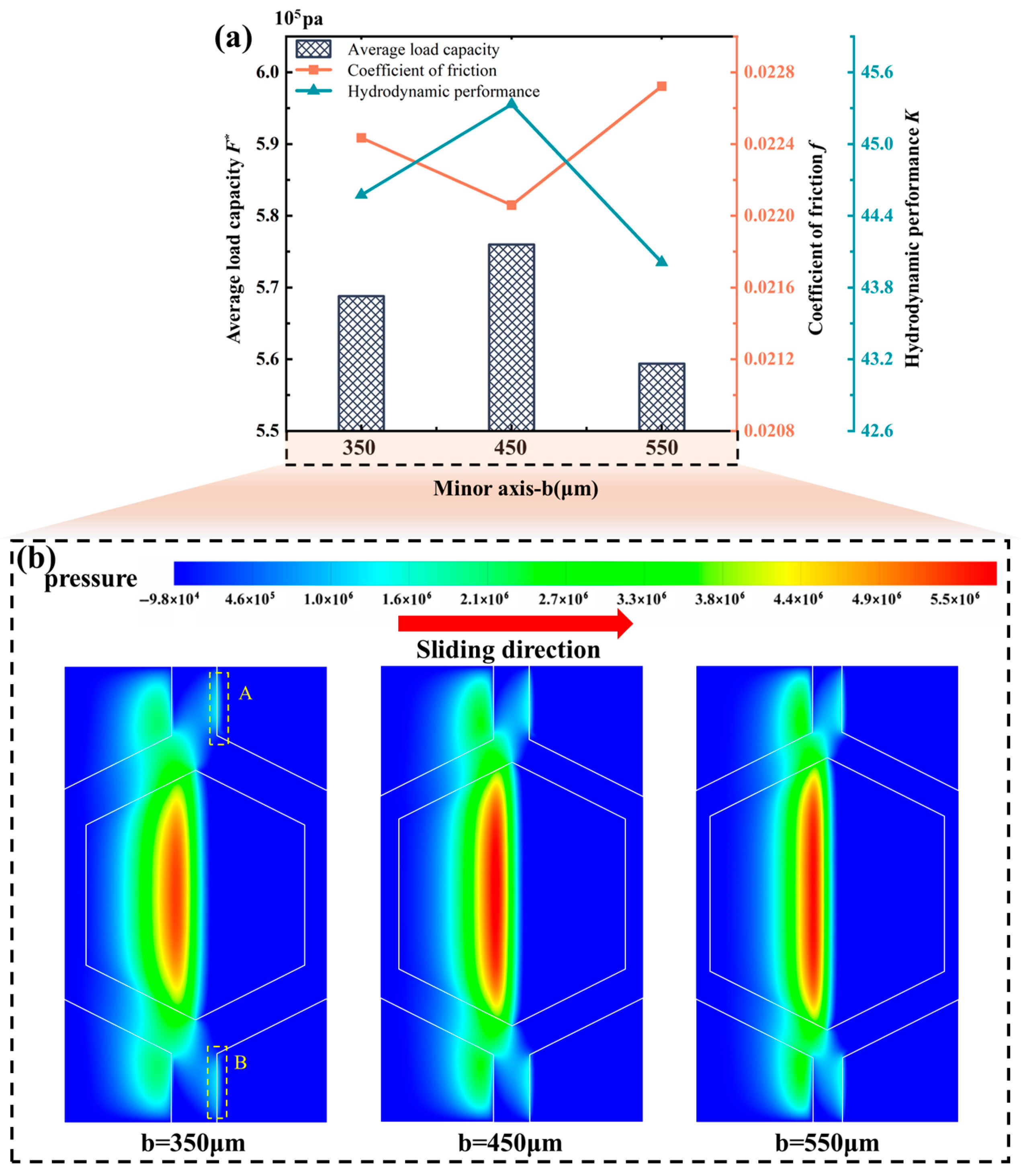
To verify the accuracy of the simulation, lubrication simulation models with different minor axis dimensions were established based on the texture dimensions used in the experiment. The hydrodynamic performance of BHT with different minor axis under the same lubrication conditions is shown in Figure 8a. The F* of the oil film initially increases and then decreases with the increase of the minor axis of the BHT. Conversely, the f exhibits an inverse correlation with F*, while the K demonstrates congruent variation with F*. When the minor axis of the BHT is 450 μm, the oil film load-carrying capacity is higher F*, which causes it to exhibit a lower f and a higher K.
The pressure cloud distribution of different minor axis BHT is shown in Figure 8b. These distributions exhibit consistent patterns, with positive pressure areas concentrated at the same locations in the BHT unit. Among them, the positive pressure in regions A and B is due to the fact that the sudden disappearance of the texture decreases the cross-sectional area as the fluid flows out of the biomimetic structure, thereby increasing the oil film pressure. Moreover, the area ratio of the BHT and the area share of the positive pressure region gradually decrease with the increase of the minor axis size. When the area ratio of BHT is too large, it increases the shear force between the fluid and the texture, leading to a higher COF. When the area share of the positive pressure region of BHT is too small, it causes the average load-carrying capacity of the texture surface to decrease, leading to a higher COF. Therefore, the COF of the texture shows a tendency of decreasing and then increasing with the increase of the minor axis, and both too small and too large minor axis sizes increase the COF of the BHT. The COF of the specimens were lowest when the minor axis dimension was 450 μm. This is consistent with the trend observed in the experiments, indicating that the simulation model can effectively reflect the lubrication performance of the BHT biomimetic texture.

3.3. Lubrication Mechanism of BHT

The BHT can be regarded as a combination of perpendicular grooves and inclined grooves, as illustrated in Figure 9a. This section compares three groove-type textured surfaces to understand the lubrication mechanism of BHT.
According to Figure 9b, all textured surfaces demonstrate enhanced hydrodynamic effects compared to the untextured surface. Perpendicular grooves facilitate hydrodynamic pressure accumulation [37,38], exhibiting the most significant enhancement, followed by BHT, while inclined grooves show minimal improvement. The intermediate performance of BHT results from the bidirectional interconnected network between the two types of grooves. Continuous inclined grooves establish stable pressure-relief channels, thereby reducing further pressure buildup in perpendicular grooves. This explains why BHT exhibits decreased load-bearing capacity relative to pure perpendicular grooves.
Figure 10 illustrates the velocity contour map and vector distribution within BHT units at different locations. The initial flow of the lubricant primarily follows the moving direction of friction pair. However, the walls of inclined grooves significantly guide the lubricant flow trajectories, causing localized flow fields to form that align closely with the groove orientation when the lubricant passes through inclined groove zones. Furthermore, in the interconnected regions between perpendicular and inclined grooves, pressurized lubricant is extruded from perpendicular grooves into inclined grooves. This phenomenon explains why inclined grooves diminish the pressure accumulation effect in perpendicular grooves. Nevertheless, the presence of inclined grooves redirects lubricant flow and increases flow velocity, thereby enhancing lubricant distribution and replenishment efficiency [37,38]. Consequently, the lubrication mechanism of BHT originates from the synergistic interplay between hydrodynamic pressure generation in perpendicular grooves and the flow-guiding function of inclined grooves.

3.4. The Effect of Parameters on Hydrodynamic Lubrication

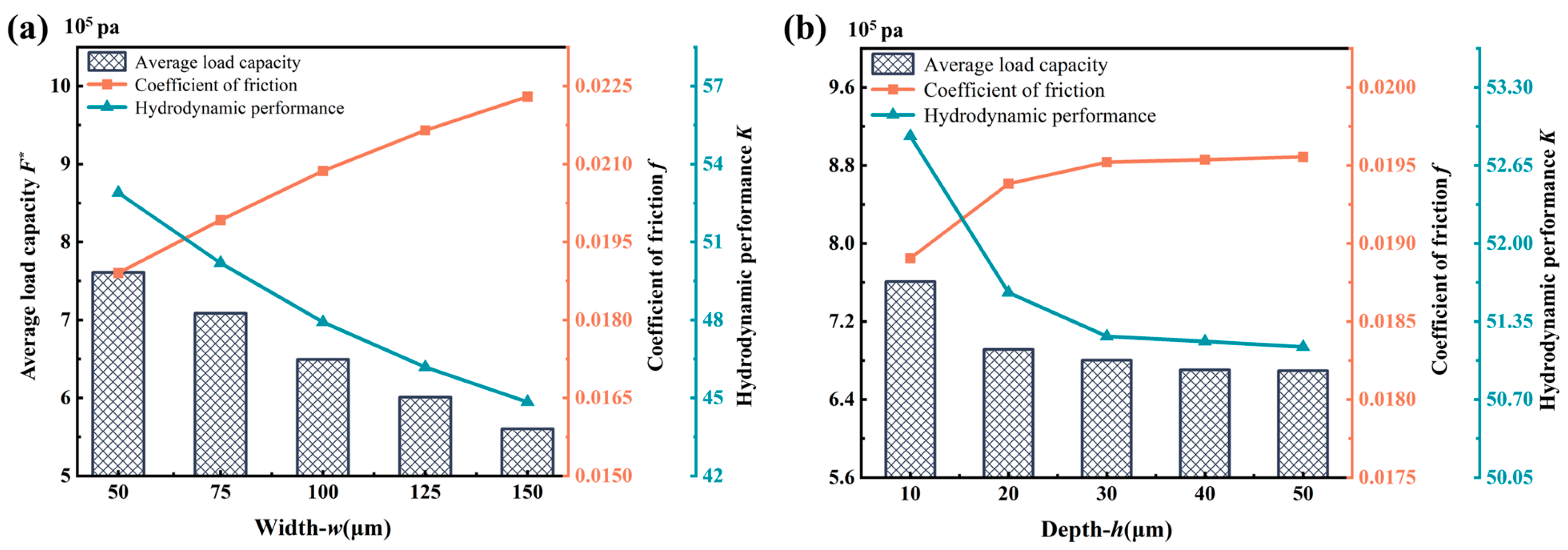
The BHT includes h = 10 μm, b = 450 μm, and θ = 60° as fixed parameters. The effect of the w (50 μm, 75 μm, 100 μm, 125 μm, and 150 μm) of BHT on K is investigated. According to Figure 11a, under the same lubrication conditions, F* and K exhibit an overall decreasing trend with increasing width of BHT, and f shows the opposite trend. As the texture width increases, the leakage path of the lubricant from the high-pressure region to the low-pressure region expands. This phenomenon leads to a more dispersed pressure distribution, making it challenging to form a concentrated high-pressure zone on the contact surface, thereby diminishing the effectiveness of hydrodynamic lubrication and increasing the COF. Therefore, the width of the texture is not too wide for BHT.
The BHT includes b = 450 μm, θ = 60°, and w = 50 μm as fixed parameters. And the effect of the h (10 μm, 20 μm, 30 μm, 40 μm, and 50 μm) of BHT on K is investigated. Figure 11b demonstrates that when the depth is less than 20 μm, both F* and K decrease rapidly with the increase of depth. At depths greater than 20 μm, the decreases in F* and K become smaller. An excessive depth reduces the lubricant flow velocity gradient and shear force, preventing timely replenishment of the friction surface and weakening the secondary lubrication effect, thus weakening the hydrodynamic performance and increasing the COF.
The BHT includes h = 10 μm, b = 450 μm, and w = 50 μm as fixed parameters. And the effect of the θ (50°, 60°, 70°, 80°, 90°) of BHT on K is investigated. As shown in Figure 12, the F* and K increase and then decrease as the texture angle increases, achieving a maximum value at 70°, and f is taken as a minimum. The angle of the BHT significantly affects the ratio of perpendicular and inclined grooves. On one hand, the length of straight grooves perpendicular to the direction of motion increases with increasing angle, improving the K of the BHT. On the other hand, as the angle continues to increase, the inclined groove tends to be more parallel to the direction of motion, exacerbating pressure leakage and thus hindering pressure buildup. Therefore, there exists an optimum BHT angle within the value range that maximizes the hydrodynamic performance.

3.5. Parameters Optimization Based on RSM

In order to obtain the BHT design parameters for optimum tribological performance, using Minitab22 software and the CCD central composite method of RSM, a four-factor, five-level test was conducted with K as the response variable. The minor axis, width, depth, and angle of the BHT were selected as influencing factors. Based on the simulation results from the single-factor test, the high and low levels of these factors used in the study are shown in Table 2. K was used as the response variable to characterize texture performance. Thirty-one sets of composite tests for texture shape and structural parameters were designed, with the corresponding K for each set obtained through simulation, as shown in Table 3.
Based on the data from Table 3, a regression model was fitted with K as the response value:
K = 33.1 + 0.258 b 0.13326 w 0.1702 h + 0.867 θ 0.000272 b 2 0.00578 θ 2
As shown in Table 4, the p-value of the response model coefficient is less than 0.0001, much lower than 0.05, indicating a significant impact on the model. The p-value of the misfit term is 0.105, and the F-value is 2.8, both greater than 0.05, indicating that the misfit term is not significant and confirming the high fitting accuracy of the response model. The multivariate coefficient (R2), the adjusted fit coefficient (R2_adj), and the predictive coefficient (R2_pred) are 0.9724, 0.9654, and 0.9402, respectively, all close to 1, demonstrating that the response model is well correlated and suitable for optimizing BHT parameters.
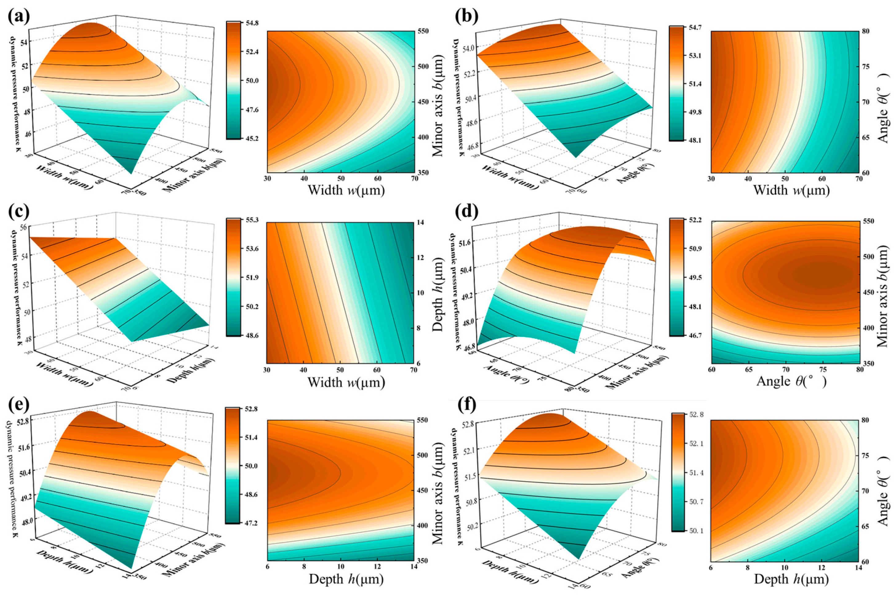
Figure 13 shows the response surface and contour plots illustrating the effect of the interaction between texture design parameters on the K. It can be concluded that the width of the texture has the most significant effect on the K, followed by the minor axis, depth, and angle of the texture. Moreover, there is a maximum value of BHT on the minor axis and angle, which is consistent with the results obtained above.
The maximum value of K is achieved when the minor axis is 475 μm, the width is 30 μm, the depth is 6 μm, and the angle is 75° based on the fitted regression Equation (8). The simulation solution with optimal parameters yields a K of 58.2578, which is an improvement of 8.27% compared to the maximum value of 53.8057 before optimization.
Common picosecond lasers typically achieved processing accuracy of ±5 μm, while femtosecond lasers offered higher precision (±1 μm), both meeting the accuracy requirements for optimized textures [7]. Furthermore, the texture depth (6 μm) represented approximately 0.75% of the carburized layer depth of more than 800 μm on the tooth surface (ISO 6335-5), ensuring minimal impact on gear tooth surface integrity and fatigue strength. Consequently, the optimized texture could be applied to gear tooth surfaces for subsequent experimental studies.

4. Gear Experiments

In this section, the main objective is to investigate the effect of optimized hexagonal grooves on the wear of cylindrical spur gears by conducting gear friction and wear tests and comparing the gear teeth surface wear conditions with and without texture.

4.1. Experimental Setup

According to the optimized parameters in Section 3.3, the gear specimen was reprocessed, and the processed BHT gear is shown in Figure 14.
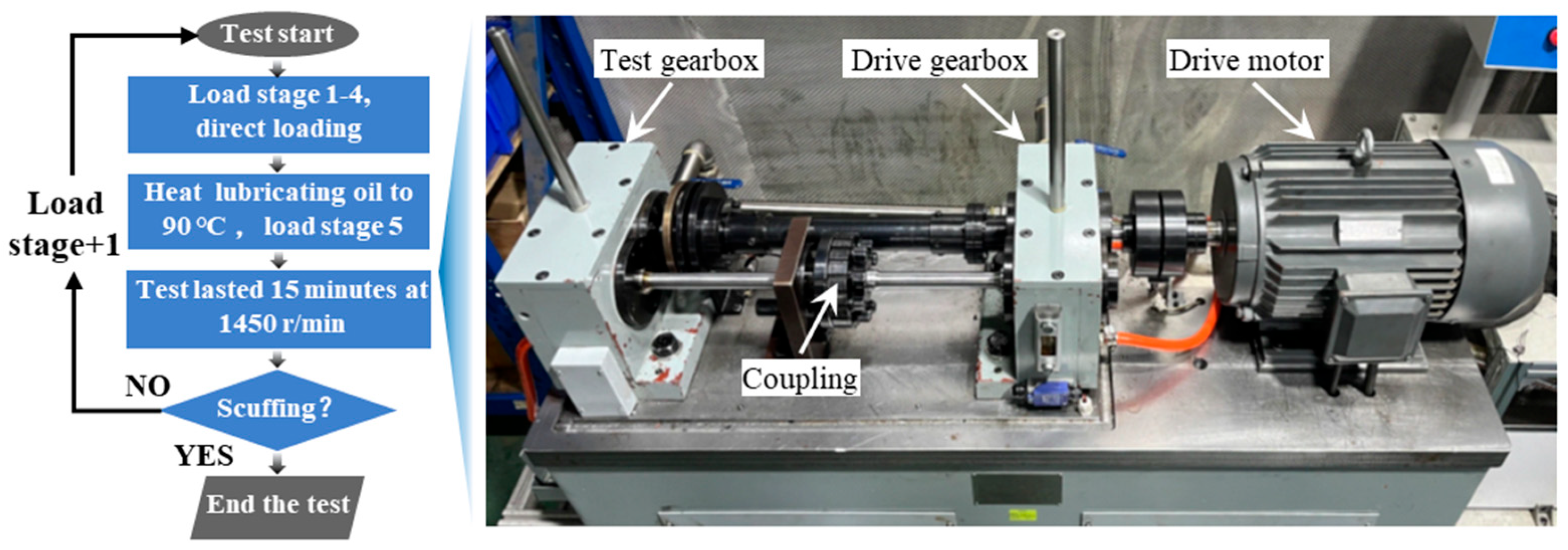
The gear friction and wear testing were carried out on the MFZG-1W (Shunmao, Jinan, China) instrument, as shown in Figure 15. Following ISO 14635-2-2000, the test is conducted using a step-by-step loading method under immersed lubrication. Each load level is run for 15 min with the large gear acting as the drive shaft at a speed of 1450 rpm. For levels 5 and above, the initial oil temperature is maintained at 90 °C. Observe tooth wear at the end of each test. If severe wear or gluing failure is observed, the test is terminated. Due to the substantial time and resource requirements associated with FZG gear testing (approximately 72 h per complete gear test cycle), the gear wear tests were conducted as a single comparative experiment following the standardized testing procedure.

4.2. Result and Discussion

4.2.1. Wear Morphology

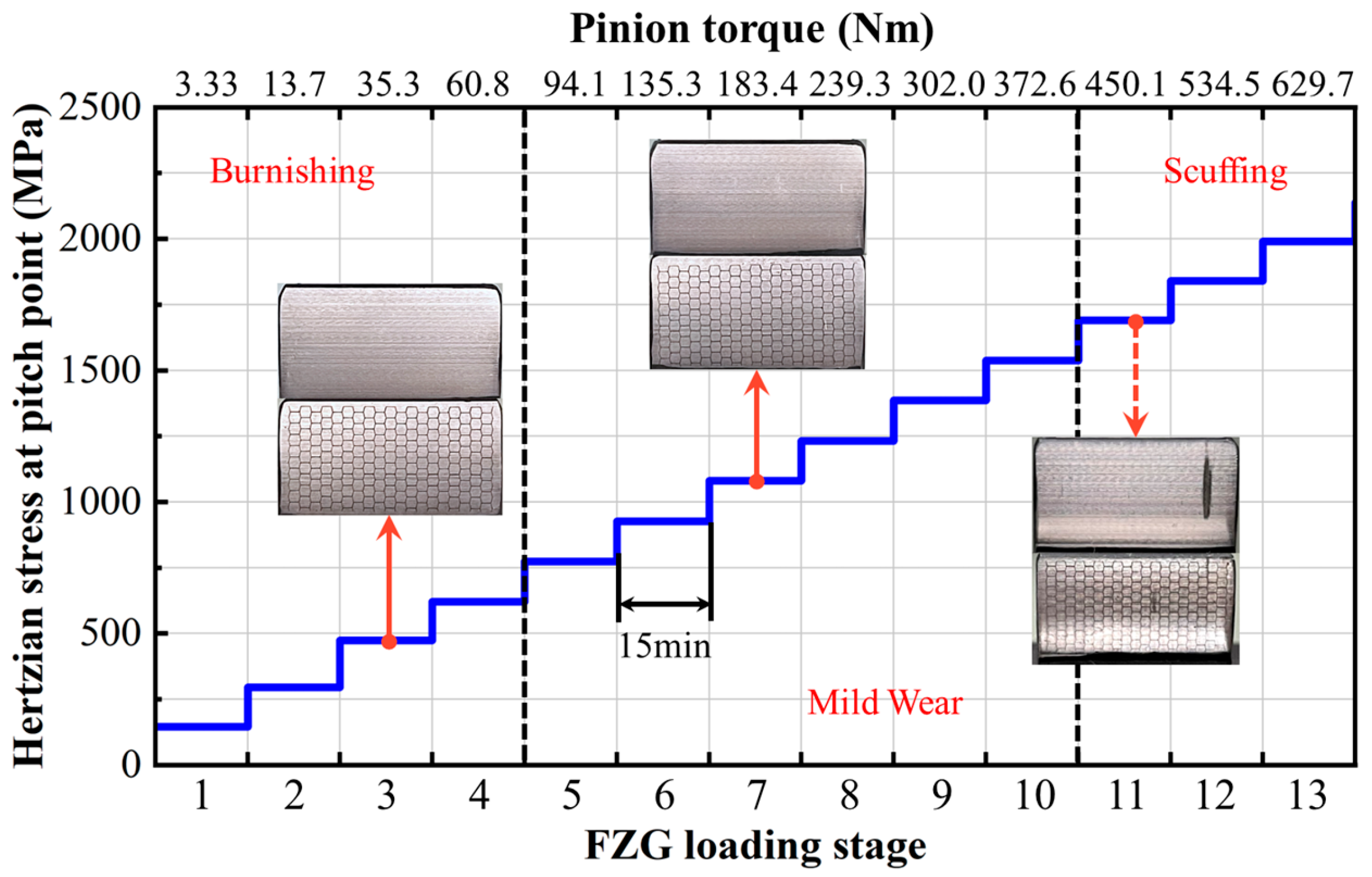
Figure 16 documents the progressive loading process, revealing that gear teeth exhibited no discernible surface damage after Stages 1–3. Following Stages 4–10, fine abrasive scratches emerged on all specimens, and untextured surfaces demonstrated marginally higher scratch density. Upon Stage 11 loading, adhesive wear manifested exclusively on untextured teeth. This occurs due to oil film rupture under overload conditions, leading to direct metal-to-metal contact between gear tooth surfaces. Subsequently, excessively high flash temperature peaks lead to metal welding. As the gear continues to move, irregular tearing occurs in the welded areas, ultimately causing damage to the entire tooth profile [43,45]. In contrast, BHT gear demonstrate no significant adhesive wear throughout the testing protocol. This phenomenon is attributable to the dual-pathway protective mechanism of the bi-directional interconnected surface textures:
(1) During light-to-medium loading (stages 1–10), grooves perpendicular to the rolling-sliding direction predominate. These grooves substantially enhance oil film load-carrying capacity by intensifying hydrodynamic effects and delaying critical film rupture.
(2) Under heavy loading (stages 11–13), grooves inclined to the rolling-sliding direction become predominant. This configuration facilitates lubricant replenishment along the tooth profile during contact, ensuring a continuous lubrication supply, thereby reducing the probability of adhesive wear initiation.
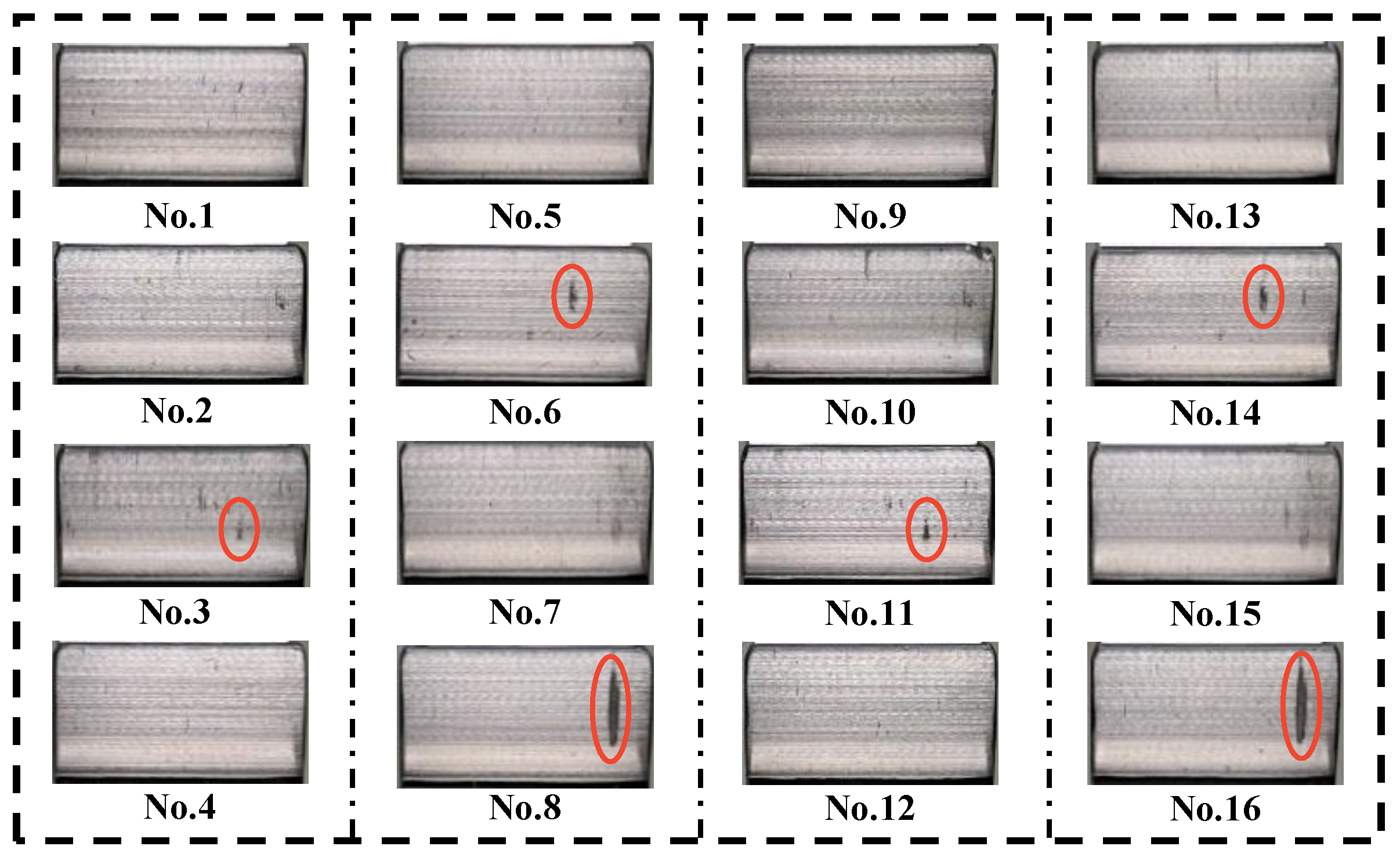
Macroscopic morphology images of all small gear tooth surfaces after testing are shown in Figure 17 and Figure 18. The red circles indicate the locations with obvious wear.The gear teeth with an 8-tooth pitch show similar wear due to the test gear’s transmission ratio of 1:1.5. Furthermore, the degree of wear on the HTB gear teeth is significantly lower than that of untextured. On smooth gear, localized scuffing manifested on teeth No. 8 and No. 16, while scratches and pits occurred on teeth No. 3, No. 6, No. 11, and No. 4. Conversely, the BHT gear showed a complete absence of scuffing phenomena across all surfaces, with only teeth No. 1, No. 5, No. 8, No. 9, No. 13, and No. 16 displaying localized scratch traces.
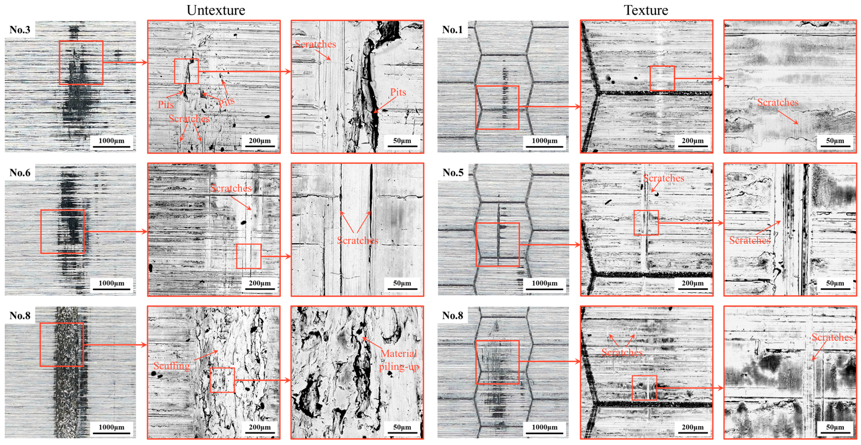
The microstructure of the severely worn tooth surface after the scuffing test was observed using an SEM, as shown in Figure 19. The untextured tooth surface exhibited ultrasevere wear characterized by scratching, delaminated pits, and scuffing features parallel to the sliding direction. This phenomenon indicates that smooth tooth surfaces undergo both adhesive wear (material transfer adhesion) and abrasive wear (hard particle plowing) during the experiment. The BHT tooth surfaces are mainly subject to abrasive wear, which manifests as striped scratches along the sliding direction, with no obvious signs of adhesive wear.
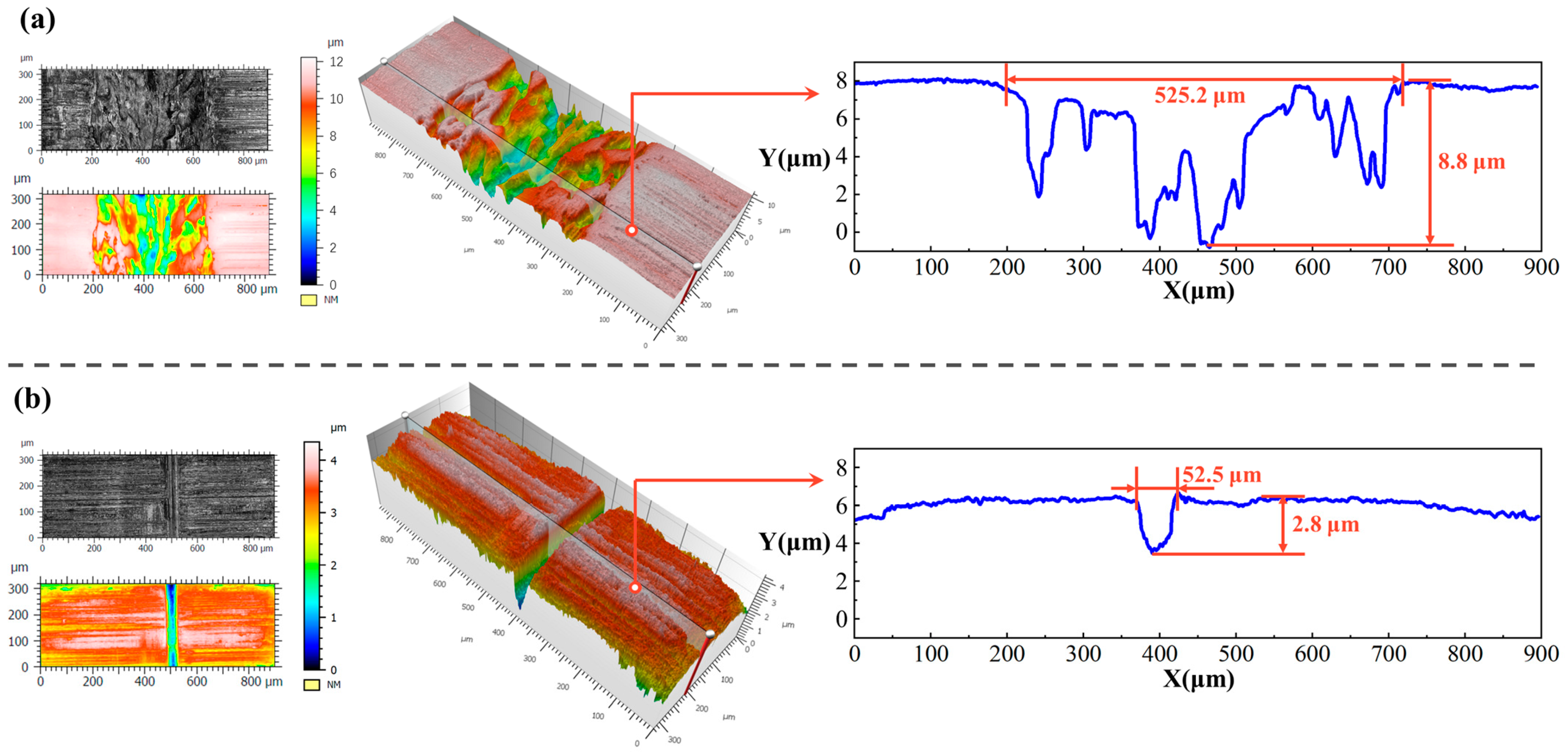
Additionally, the 3D micro-morphology of the wear scars was characterized using a laser scanning confocal microscope LSM900 (Zeiss, Oberkochen, Baden-Württemberg, Germany). Measurements were performed with a 20× objective, utilizing a lateral resolution of 0.6 μm and a vertical resolution of 0.7 μm. A standard S-filter (5 × 5 pixel median filter) was applied to remove nanoscale noise prior to analysis. The ultimately measured three-dimensional morphology is shown in Figure 20. The smooth gear surface scuffing zone exhibited hill-like extruded build-ups formed by material accumulation, with cross-sections revealing a wear track width of 525.2 μm and a maximum depth of 8.8 μm, as shown in Figure 20a. The wear region of the textured tooth surface primarily exhibits linear scratches with a uniform surface morphology, as shown in Figure 20b. The width of the wear area is 52.5 μm, with a depth of 2.8 μm, indicating a significant reduction in wear severity compared with a smooth surface.
Results from comprehensive macro-scale surface feature analysis, SEM microscopy, and 3D profilometry comparisons demonstrate that surface texture technology effectively mitigates scuffing, significantly reduces abrasive wear, and preserves surface structure robustness under high-load conditions. This improvement is attributed to the synergistic effect of the bidirectional texture design, which a maintains continuous lubricant supply across the contact interface while effectively entrapping and removing wear debris, thereby preventing the occurrence of adhesive wear.

4.2.2. Wear Area

The wear area ratio is a key indicator for evaluating the severity of tooth surface damage, defined as the ratio of the damaged area to the total observed area. In this study, a 3D microscope VHX-2000 device (Keyence, Oseka, Japan) was used to detect and analyze gear surface damage. The results of the wear area ratio comparison between textured tooth surfaces and untextured tooth surfaces (No. 1–8) at 5× magnification are shown in Figure 21. The red areas in the figure indicate the locations of wear. It is clearly visible that the red-marked areas on the untextured gear surfaces are significantly larger than those on the textured surfaces, indicating that the wear area ratio of untextured gear surfaces is notably higher.
Figure 22 further presents the distribution of damage areas across 16 gear teeth. The chart shows that untextured gear surfaces not only have a higher average wear area ratio but also exhibit more significant data distribution fluctuations. Specifically, the average wear area ratio for untextured gear surfaces is 2.356%, with a standard deviation of 2.503, reflecting greater variability. In contrast, the average wear area ratio of textured tooth surfaces is significantly reduced to 0.381%, with a standard deviation of 0.269, indicating smaller wear and more uniform distribution. Compared to untextured tooth surfaces, the average wear area ratio of textured tooth surfaces is reduced by 82.83%. This phenomenon is primarily attributed to the BHT texture effectively preventing adhesive wear and reducing the probability of abrasive wear, resulting in a significantly lower wear area on the textured surface compared to the smooth surface.

4.2.3. Wear Amount

Tooth profile deviation (TPD) serves as a primary parameter for assessing gear tooth surface accuracy. The TPD of all teeth for both textured and untextured gears pre-test and post-test was obtained with the Gear Measurement Center P16 instrument (Klingelnberg, Hagen, North Rhine-Westphalia, DE, Germany). The difference in TPD pre-test and post-test was used as another evaluation criterion for the amount of tooth wear.
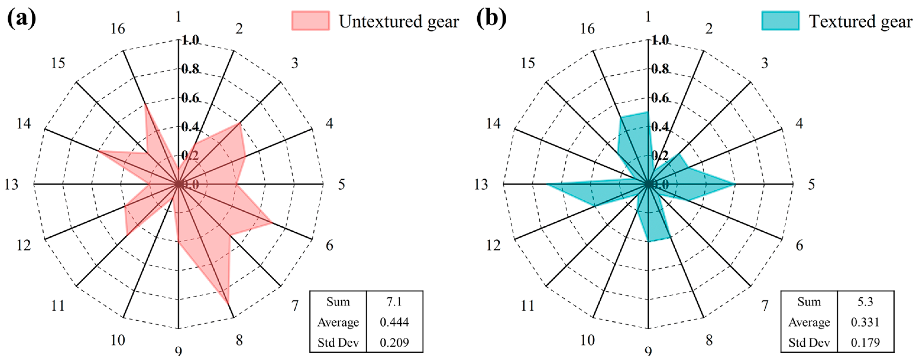
The distribution curve of the wear amount of TPD for all gear teeth with regard to BHT gears and untextured gears is shown in Figure 23. It can be seen that the area of the red region is significantly larger than that of the green region. The finding indicates that the total change value post-test is greater for untextured tooth surfaces than for textured tooth surfaces. The TPD change of 7.1 µm across all teeth of untextured gears, with an average wear amount of 0.4438 µm and standard deviation of 0.0437 µm2. For BHT gears, the cumulative TPD change measured 5.3 µm, with an average wear amount of 0.3313 µm and a standard deviation of 0.0321 µm2. This represents a 25.35% reduction in wear for BHT gears compared to untextured.

4.2.4. Lubricant Temperature

To ensure measurement reliability, three temperature readings were taken at 20-s intervals using a PT100 temperature sensor (Meikong, Hangzhou, China) during the final minute of each loading stage test (after temperature stabilization). The maximum deviation among the three readings was ±0.5 °C. Use the average of the three measurements as the lubricant temperature at the end of the test.
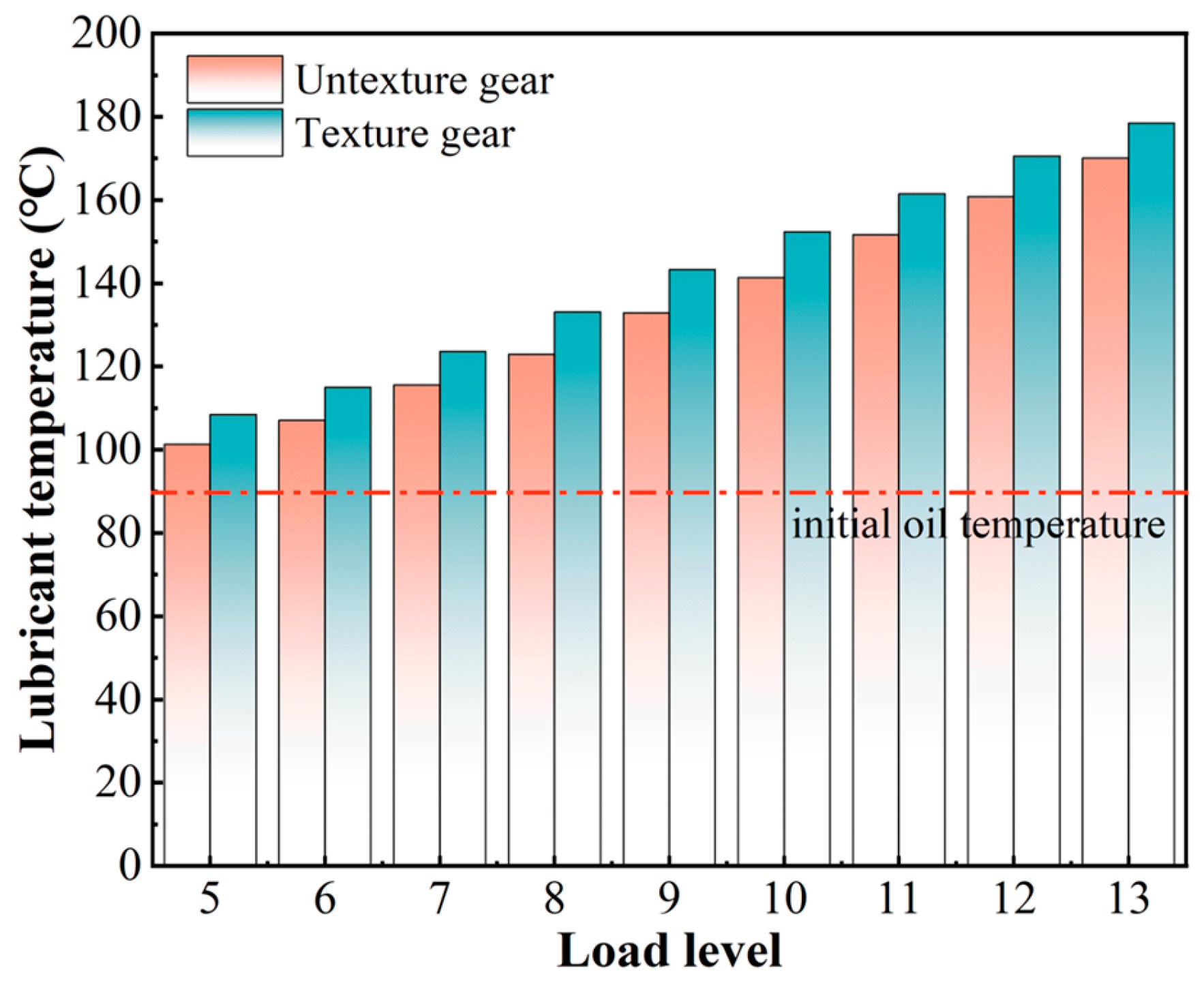
Figure 24 depicts the evolution of bulk lubricant temperature within the gearbox under progressively increasing load conditions (Stages 5–13). The oil temperature exhibits a systematic upward trend with escalating loads. A pivotal observation reveals that the BHT gears consistently operate at higher bulk oil temperatures (7.2–11.0 °C) than their untextured counterparts under identical loading. This temperature elevation trend diverges from prior findings [22,23], primarily attributable to the unique characteristics of the bidirectional interconnectivity texture. The bidirectional texture promotes lubricant flow along both the tooth profile and width directions, enhancing overall lubrication efficiency while absorbing additional meshing friction heat through augmented convective heat transfer. Consequently, textured gears exhibit elevated oil temperatures compared to smooth surfaces in oil-immersed conditions.
In summary, our findings reveal that the elevated bulk oil temperature is an indicator of enhanced heat dissipation, not a detrimental effect. The bidirectional texture simultaneously combats wear through improved lubrication and manages interfacial heat. For industrial gear design, this translates into a practical strategy for achieving higher power density and reliability in demanding applications (such as in wind energy, automotive transmissions, and aerospace). By implementing this surface engineering approach, manufacturers can potentially extend gear life under extreme operating conditions, reduce the frequency of maintenance intervals, and improve overall transmission efficiency.

5. Conclusions

In this work, we proposed a novel design approach of bioinspired hexagonal texture for wear reduction under rolling-sliding line contact, with parametric optimization of groove size and angle. The numerical model for BHT was established by using CFD, and the corresponding specimens were fabricated via laser texturing. Simulation and experimental results elucidated the influence of BHT and its design parameters on fluid lubrication and the tribological performance of the friction pair. The main conclusions are given as follows:
(1) CFD-based simulations demonstrated that grooves perpendicular to the rolling-sliding direction provided enhanced hydrodynamic performance, while inclined grooves facilitated lubricant replenishment along the rolling-sliding direction, thereby improving lubrication supply efficiency. Consequently, the BHT achieved synergistic improvements in both lubrication and tribological performance.
(2) Through Response Surface Methodology optimization, the BHT was redesigned with critical parameters refined to minor axis 475 μm, included angle 75°, groove width 30 μm, and groove depth 6 μm. This optimized geometry demonstrated an 8.27% increase in hydrodynamic performance relative to baseline designs, as validated by comparative CFD simulations.
(3) FZG gear tests demonstrated that the BHT significantly enhanced the wear resistance of the tooth surface. The average wear area rate of the tooth surface was reduced by 82.83%, the change in average tooth profile deviation decreased by 25.35%, and the load stage at which severe scuffing occurs was delayed from level 11 to level 13.
(4) Compared to untextured gears, BHT gears exhibited a 7–11 °C increase in bulk lubricant temperature. This indicates that the continuous groove network provided directed oil flow pathways, thereby enhancing thermal management efficiency at the meshing interface (manifested as active cooling effects). These findings elucidated the dual-mechanism coupling effect of biomimetic textures in tribological enhancement, establishing a new paradigm for gear surface engineering.

6. Limitations and Future Work

The biomimetic hexagonal texture with dual-orientation groove interconnectivity enhances gear tooth flank lubrication and tribological performance, yet limitations persist. FZG gear tests revealed that as meshing stress increased from 0.2 GPa to 2.3 GPa, the actual flank contact conditions transitioned through different lubrication regimes. This resulted in a pronounced nonlinear evolution in tribological behavior, characterized by a non-linear increase in the friction coefficient, a transition from mild to severe wear rates, and the potential onset of lubricant film collapse and scuffing. These factors were not fully captured by our current isothermal CFD model. Subsequent work will build upon this research to establish a thermoelastic hydrodynamic lubrication (TEHL) model incorporating micro-contact effects and develop a comprehensive multi-objective optimization framework integrating hydrodynamic, thermal, and wear performance considerations. These synergistic advancements will enable more accurate performance predictions while delivering more profound insights into the lubrication mechanisms and tribological behavior of BHT-enhanced tooth surfaces.

Author Contributions

Y.W.: Writing—original draft, Writing—review & editing, Visualization, Software, Investigation, Formal analysis, Conceptualization. S.L.: Writing—review & editing, Supervision, Conceptualization, Funding acquisition. T.G.: Writing—review & editing, Supervision, Software. J.M.: Writing—review & editing, Supervision, Funding acquisition. D.W.: Writing—review & editing, Software. X.C.: Writing—review & editing, Supervision, Resources, Conceptualization, Funding acquisition. All authors have read and agreed to the published version of the manuscript.

Funding

This research was funded by the National Natural Science Foundation of China grant number 51875491 and by the National Natural Science Foundation of China grant number 52205055.

Data Availability Statement

Data will be made available on request.

Conflicts of Interest

Author Dongfei Wang was employed by China Academy of Machinery Zhengzhou Research Institute of Mechanical Engineering Co., Ltd. No conflict of interest exits in the submission of this manuscript, and manuscript is approved by all authors for publication. I would like to declare on behalf of my co-authors that the work described was original research that has not been published previously, and not under consideration for publication elsewhere, in whole or in part. All the authors listed have approved the manuscript that is enclosed. The authors declare that they have no known competing financial interests or personal relationships that could have appeared to influence the work reported in this paper.

References

  1. Liang, X.; Zuo, M.; Feng, Z. Dynamic modeling of gearbox faults: A review. Mech. Syst. Signal Process. 2018, 98, 852–876. [Google Scholar] [CrossRef]
  2. Miler, D.; Hoic, M. Optimisation of cylindrical gear pairs: A review. Mech. Mach. Theory 2020, 156, 104156. [Google Scholar] [CrossRef]
  3. Feng, K.; Ji, J.; Ni, Q.; Beer, M. A review of vibration-based gear wear monitoring and prediction techniques. Mech. Syst. Signal Process. 2023, 182, 109605. [Google Scholar] [CrossRef]
  4. Liu, J.; Liu, H.; Zhu, C.; Parker, R. Effects of lubrication on gear performance: A review. Mech. Mach. Theory 2020, 145, 103701. [Google Scholar] [CrossRef]
  5. Li, Z.; Guan, Q.; Liu, S.; Bao, J.; Ding, H.; Wang, W. Friction-reducing and anti-wear performance of SiO2-Coated TiN nanoparticles in gear oil. Wear 2024, 538, 205219. [Google Scholar] [CrossRef]
  6. Marian, M.; Almqvist, A.; Rosenkranz, A.; Fillon, M. Numerical micro-texture optimization for lubricated contacts—A critical discussion. Friction 2022, 10, 1772–1809. [Google Scholar] [CrossRef]
  7. Wang, H.; Deng, D.; Zhai, Z.; Yao, Y. Laser-processed functional surface structures for multi-functional applications-a review. J. Manuf. Process. 2024, 116, 247–283. [Google Scholar] [CrossRef]
  8. Xiao, Q.; Wang, X.; Wang, Y.; Zheng, W.; Xu, J.; Luo, X.; Sun, J.; Zhang, L. Beyond smoothness: The art of surface texturing battling against friction. Int. J. Extrem. Manuf. 2025, 7, 022014. [Google Scholar] [CrossRef]
  9. Lin, O.; Xiao, G.; Liu, S.; Zhou, Y.; Liu, Z.; Huang, J.; Yin, K. Rapid multiscale surface texture manufacturing process using hybrid laser belt machining. J. Mater. Process. Technol. 2024, 319, 118092. [Google Scholar] [CrossRef]
  10. Wang, H.; Huang, J.; Wang, B.; Zhang, Y.; Wang, J. Study on the tribological behavior of laser surface texturing on silicon nitride ceramic under water lubrication. Lubricants 2025, 13, 21. [Google Scholar] [CrossRef]
  11. Huang, Q.; Wu, C.; Shi, X.; Zhang, K. Topology optimization of AISI 4140 steel with surface texture filled by multi-solid lubricants for enhancing tribological properties. Friction 2024, 12, 2033–2051. [Google Scholar] [CrossRef]
  12. Zhao, X.; Zhang, Y. Tribological and dynamic performance analysis of rolling bearings with varied surface textures operating under lubricant contamination. Wear 2023, 532, 205109. [Google Scholar] [CrossRef]
  13. Xue, L.; Yan, Z.; Jiang, Y.; Sun, T. Influences of Sharkskin Texture on Lubrication Performance of Elastic Bearing Friction Pairs. Tribol. Lett. 2024, 72, 103. [Google Scholar] [CrossRef]
  14. Wang, X.; Li, C.; Zhang, Y.; Said, Z.; Debnath, S.; Sharma, S.; Yang, M.; Gao, T. Influence of texture shape and arrangement on nanofluid minimum quantity lubrication turning. Int. J. Adv. Manuf. Technol. 2022, 119, 631–646. [Google Scholar] [CrossRef]
  15. Long, R.; Shang, Q.; Sun, S.; Wang, S.; Ma, C.; Zhang, J.; Marian, M. Influence of Monstera riedrichsthalii bionic textures on the tribological and vibration behavior of rolling bearings. Friction 2025, 13, 9440949. [Google Scholar] [CrossRef]
  16. Liu, Z.; Shen, Y.; Liu, J.; Qu, J.; Xu, J.; Li, C. Effects of double-sided textures matching on friction and wear performance in reciprocating contact interface. Wear 2024, 556, 205522. [Google Scholar] [CrossRef]
  17. Wu, D.; Liang, X.; Wen, X.; Meng, Z.; Yu, Z.; He, Y.; Dai, P.; Yu, Y.; Li, N. Experimental study of diesel engine deposits on failure of honed cylinder liner surface texture. Eng. Fail. Anal. 2025, 174, 109476. [Google Scholar] [CrossRef]
  18. He, Z.; Guo, Y.; Si, J.; Li, N.; Jia, L.; Zou, Y.; Wang, H. Numerical optimization analysis of floating ring seal performance based on surface texture. Lubricants 2024, 12, 241. [Google Scholar] [CrossRef]
  19. Lu, P.; Wood, R. Tribological performance of surface texturing in mechanical applications—A review. Surf. Topogr. Metrol. Prop. 2020, 8, 043001. [Google Scholar] [CrossRef]
  20. Bian, B.; Zhang, Z.; Li, L.; Chao, Q.; Yuan, H.; Liu, Z. Lubrication, friction and wear characteristics of textured surface slipper pairs in axial piston pumps. Lubricants 2024, 12, 370. [Google Scholar] [CrossRef]
  21. Andreas, R.; Philipp, G.; Carsten, G.; Henara, L. Surface texturing in machine elements a critical discussion for rolling and sliding contacts. Adv. Eng. Mater. 2019, 1099, 194. [Google Scholar] [CrossRef]
  22. Gupta, N.; Tandon, N.; Pandey, R. An exploration of the performance behaviors of lubricated textured and conventional spur gearsets. Tribol. Int. 2018, 128, 376–385. [Google Scholar] [CrossRef]
  23. Gupta, N.; Tandon, N.; Pandey, R.; Vidyasagar, K.; Kalyanasundaram, D. Tribological and vibration studies of textured spur gear pairs under fully flooded and starved lubrication conditions. Tribol. Trans. 2020, 63, 1103–1120. [Google Scholar] [CrossRef]
  24. Chang, X.; Renqing, D.; Liao, L.; Zhu, P.; Lin, B.; Huang, Y.; Luo, S. Study on hydrodynamic lubrication and friction reduction performance of spur gear with groove texture. Tribol. Int. 2023, 177, 107978. [Google Scholar] [CrossRef]
  25. Zhang, Z.; Li, J.; Zou, T.; Hou, W.; An, Y.; Liu, J. Effect of bionic texture on the lubrication efficiency and mechanical efficiency loss for rotating gears. Surf. Topogr. Metrol. Prop. 2024, 12, 035004. [Google Scholar] [CrossRef]
  26. Renqing, D.; Luo, S.; Chang, X. Study on hydrodynamic lubrication and friction reduction performance of cylindrical rolls with tesla valve texture. Tribol. Trans. 2023, 66, 981–991. [Google Scholar] [CrossRef]
  27. Li, J.; Zhang, G.; Du, C.; Song, T.; Wu, Y.; Zhou, Y. Various multi-scale textures morphology fabricated by combining femtosecond laser and molding process: Friction and wetting behavior. Surf. Topogr. Metrol. Prop. 2025, 13, 035006. [Google Scholar] [CrossRef]
  28. Zhu, X.; Yang, X.; Zhao, A.; Cheng, X.; Zhang, Q.; Liu, D. Tribological Characteristics of Laser Multi-scale Composite Textures for YT-15 Cemented Carbide Surface. Tribol. Lett. 2025, 73, 60. [Google Scholar] [CrossRef]
  29. Hou, Q.; Yang, X.; Cheng, J.; Wang, S.; Duan, D.; Xiao, J.; Li, W. Optimization of performance parameters and mechanism of bionic texture on friction surface. Coatings 2020, 10, 171. [Google Scholar] [CrossRef]
  30. Sharma, S.; Grewal, H. Tribological behavior of bioinspired surfaces. Biomimetics 2023, 8, 62. [Google Scholar] [CrossRef]
  31. Abdel-Aal, H.; Vargiolu, R.; Zahouani, H.; El Mansori, M. Preliminary investigation of the frictional response of reptilian shed skin. Wear 2012, 290, 51–60. [Google Scholar] [CrossRef][Green Version]
  32. Qi, C.; Jiang, F.; Yang, S. Advanced honeycomb designs for improving mechanical properties: A review. Compos. B Eng. 2021, 227, 109393. [Google Scholar] [CrossRef]
  33. Kumar, R.; Rezapourian, M.; Rahmani, R.; Maurya, H.; Kamboj, N.; Hussainova, I. Bioinspired and multifunctional tribological materials for sliding, erosive, machining, and energy-absorbing conditions: A Review. Biomimetics 2024, 9, 209. [Google Scholar] [CrossRef]
  34. Cans, C.; Baic, D. Regional specialization of reptilian scale surfaces: Relation of texture and biologic role. Science 1977, 195, 1348–1350. [Google Scholar] [CrossRef]
  35. Sanchez, J.; Estupinan, H.; Toro, A. Friction response of bioinspired AISI 52100 steel surfaces texturized by photochemical machining. Surf. Topogr. Metrol. Prop. 2021, 9, 014001. [Google Scholar] [CrossRef]
  36. Zhong, Y.; Zheng, L.; Gao, Y.; Liu, Z. Numerical simulation and experimental investigation of tribological performance on bionic hexagonal textured surface. Tribol. Int. 2019, 129, 151–161. [Google Scholar] [CrossRef]
  37. Rahmani, H.; Taghavi, S. A comprehensive model for viscoplastic flows in channels with a patterned wall: Longitudinal, transverse and oblique flows. J. Fluid Mech. 2024, 984, A32. [Google Scholar] [CrossRef]
  38. Yuan, S.; Huang, W.; Wang, X. Orientation effects of micro-grooves on sliding surfaces. Tribol. Int. 2011, 44, 1047–1054. [Google Scholar] [CrossRef]
  39. Li, L.; Li, B.; Wei, X.; Gao, Z.; Lu, Z.; Guo, H. Multi-dimensional tool wear detection using non-subsampled shearlet transform and enhanced pulse coupled neural network in optical microscopy reconstruction. Opt. Laser Technol. 2025, 187, 112849. [Google Scholar] [CrossRef]
  40. Luo, Q. Electron microscopy and spectroscopy in the analysis of friction and wear mechanisms. Lubricants 2018, 6, 58. [Google Scholar] [CrossRef]
  41. Zochowski, T.; Olszewski, A.; Fillon, M.; Galda, L.; Smykla, J. Accurate dimensional characterization of the textured inner surface of the bearing bushing by the mean of a new measurement instrument. Measurement 2025, 250, 117068. [Google Scholar] [CrossRef]
  42. Peta, K.; Stemp, W.; Stocking, T.; Chen, R.; Love, G.; Gleason, M.; Houk, B.; Brown, C. Multiscale geometric characterization and discrimination of dermatoglyphs (fingerprints) on hardened clay—A novel archaeological application of the gelsight max. Materials 2025, 18, 2939. [Google Scholar] [CrossRef]
  43. Chen, T.; Zhu, C.; Chen, J.; Liu, H. A review on gear scuffing studies: Theories, experiments and design. Tribol. Int. 2024, 196, 109741. [Google Scholar] [CrossRef]
  44. Zhang, N.; Guo, S.; He, G.; Jiang, B.; Zhou, L.; Chen, Y.; Liu, Y. Failure analysis of the carburized 20MnCr5 gear in fatigue working condition. Int. J. Fatigue 2022, 161, 106938. [Google Scholar] [CrossRef]
  45. Chen, T.; Wei, P.; Zhu, C.; Zeng, P.; Li, D.; Parker, R.; Liu, H. Experimental investigation of gear scuffing for various tooth surface treatments. Tribol. Trans. 2023, 66, 35–46. [Google Scholar] [CrossRef]
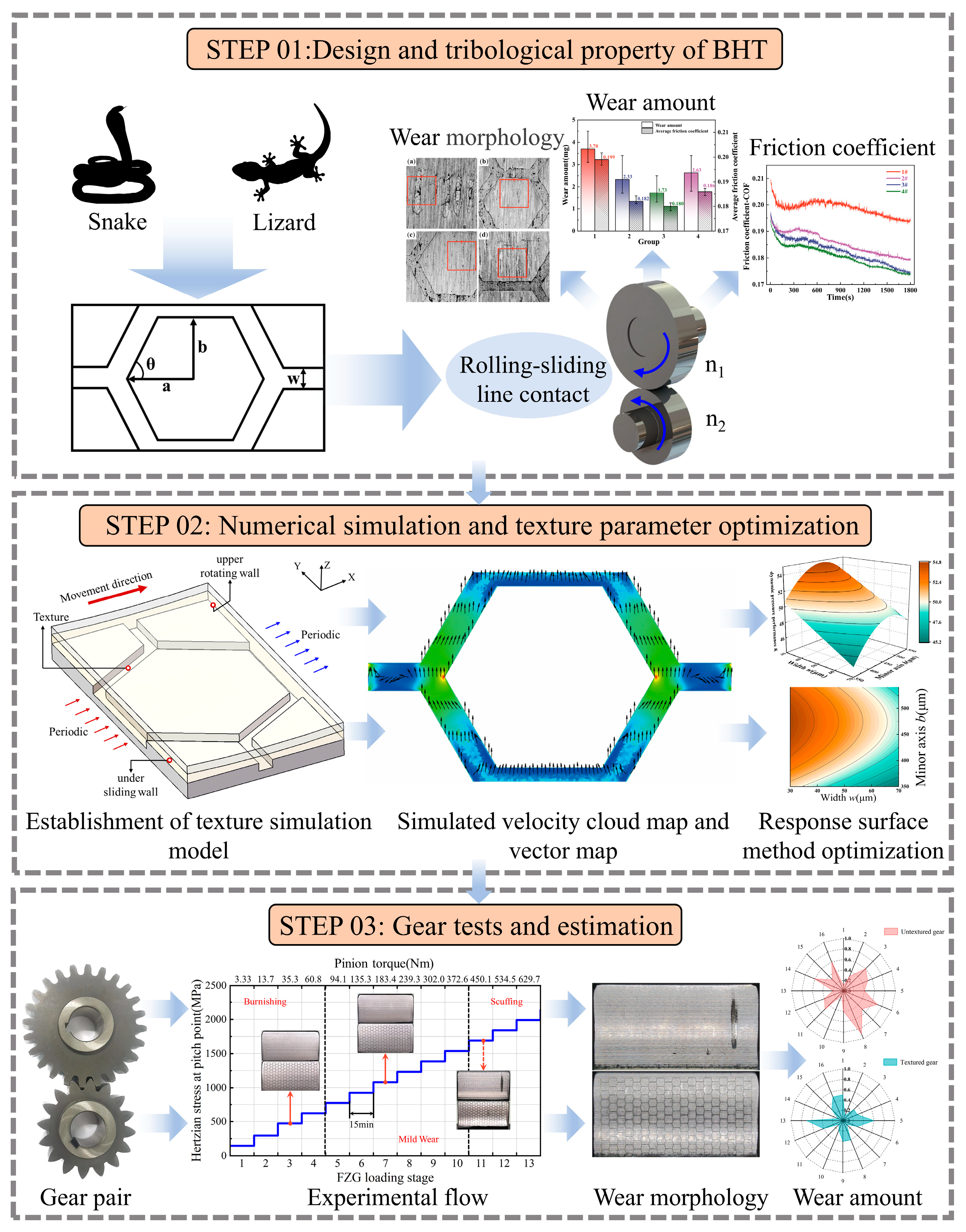
Figure 1. The framework of BHT design, optimization and experimentation.
Lubricants 13 00420 g001
Figure 2. Design of BHT: (a) hexagonal structures in bio-skin; (b) characteristic parameters of textured units.
Lubricants 13 00420 g002
Figure 3. Twin-disc testing of textured rollers: (a) principle of laser processing; (b) specimens; (c) textured 3D morphology; (d) MMS-2A wear tester.
Lubricants 13 00420 g003
Figure 4. Roller Tribological Properties: (a) friction coefficients; (b) wear amount and average friction coefficients.
Lubricants 13 00420 g004
Figure 5. SEM image of textured and untextured Roller wear after test.
Lubricants 13 00420 g005
Figure 6. Optimization process for BHT textures.
Lubricants 13 00420 g006
Figure 7. Lubrication model of BHT unit: (a) overall view; (b) cross-sectional view; (c) exploded view.
Lubricants 13 00420 g007
Figure 8. Effect of different BHT minor axis on lubrication performance: (a) average load capacity; (b) pressure clouds for different BHT minor axis.
Lubricants 13 00420 g008
Figure 9. Effect of different BHT types on hydrodynamic pressure: (a) split diagram; (b) average load capacity.
Lubricants 13 00420 g009
Figure 10. Simulated velocity cloud map and vector map of BHT with minor axis (450 μm).
Lubricants 13 00420 g010
Figure 11. Effect of different BHT parameters on lubrication performance: (a) width; (b) depth.
Lubricants 13 00420 g011
Figure 12. Effect of different BHT angle on lubrication performance: (a) average load capacity, (b) pressure clouds for different BHT angle.
Lubricants 13 00420 g012
Figure 13. Response of the BHT design parameters to K: (a) w and b; (b) w and θ; (c) w and h; (d) θ and b; (e) h and b; (f) h and θ.
Lubricants 13 00420 g013
Figure 14. Processing and measurement of textured gears: (a) textured gear; (b) gear side projection; (c) texture morphology; (d) texture size.
Lubricants 13 00420 g014
Figure 15. Experimental flow and testing machine.
Lubricants 13 00420 g015
Figure 16. Testing loading process.
Lubricants 13 00420 g016
Figure 17. Untextured gear teeth surface after test.
Lubricants 13 00420 g017
Figure 18. Textured gear teeth surface after test.
Lubricants 13 00420 g018
Figure 19. SEM image of textured and untextured tooth surface wear after test.
Lubricants 13 00420 g019
Figure 20. 3D microstructure of tooth surfaces after testing: (a) untextured No. 8 tooth; (b) BHT No. 5 tooth.
Lubricants 13 00420 g020
Figure 21. Wear area ratio of gear surface after test.
Lubricants 13 00420 g021
Figure 22. Wear area ratio distribution of textured and untextured gear.
Lubricants 13 00420 g022
Figure 23. Radar chart of wear amount: (a) untextured gear; (b) textured gear.
Lubricants 13 00420 g023
Figure 24. The changes of lubricant temperature with the load level in the gearbox.
Lubricants 13 00420 g024
Table 1. Chemical composition of 20MnCr5 according to the standard (DIN EN 10084).
ElementsCSiMnCrS
Weight %0.17~0.22≤0.41.00~1.401.00~1.30≤0.035
Table 2. Design parameters and their value of BHT.
LevelsMinor Axis b (μm)Width w (μm)Depth h (μm)Angle θ (°)
−235030660
−140040865
0450501070
1500601275
2550701480
Table 3. Design and results of RSM experiments.
No.Independent VariableResponse Value
b (μm)w (μm)h (μm)θ (°)K
14006086548.7954
245050108052.2020
35004087553.8057
445050107052.0688
540060126548.4337
640040126551.4747
750040126552.4014
84004086551.6537
95004086553.1905
1040060127549.1945
115006086550.5708
1250060127550.7184
134505067053.5461
1445050107052.1983
1535050107048.4517
1645050106051.0894
1740040127551.7179
184004087552.3394
1945050147051.3411
2045050107051.8583
214006087549.2929
2245030107054.6773
2355050107050.5640
2450060126550.0887
2545050107051.8083
2645070107049.3598
2745050107052.1283
285006087551.1719
2950040127553.0292
3045050107052.2983
3145050107051.8583
Table 4. Variance analysis of K.
SourceSum of
Squares
dfMean SquareF-Valuep-ValueNote
Model72.11612.02140.71<0.0001Significant
b11.07111.07129.59<0.0001
w42.62142.62498.92<0.0001
h2.7812.7832.57<0.0001
θ1.9811.9823.13<0.0001
b213.46113.46157.57<0.0001
θ20.6117.140.0130.6100
Residual2.05240.09
Lack of
Fit
1.83180.102.780.1050Not
Significant
Pure Error0.2260.04
Cor total74.1730
R-squared 0.9724
Disclaimer/Publisher’s Note: The statements, opinions and data contained in all publications are solely those of the individual author(s) and contributor(s) and not of MDPI and/or the editor(s). MDPI and/or the editor(s) disclaim responsibility for any injury to people or property resulting from any ideas, methods, instructions or products referred to in the content.