Article

Comparative Analysis of Emulsion, Cutting Oil, and Synthetic Oil-Free Fluids on Machining Temperatures and Performance in Side Milling of Ti-6Al-4V

1
Manufacturing Technology Institute (MTI), RWTH Aachen University, Campus-Boulevard 30, 52074 Aachen, Germany
2
Fraunhofer Institute for Production Technology IPT, Steinbachstr. 17, 52074 Aachen, Germany
*
Author to whom correspondence should be addressed.
Lubricants 2025, 13(9), 396; https://doi.org/10.3390/lubricants13090396
Submission received: 4 July 2025 / Revised: 6 August 2025 / Accepted: 3 September 2025 / Published: 6 September 2025
(This article belongs to the Special Issue Friction and Wear Mechanism Under Extreme Environments)

Abstract

During machining, most of the mechanical energy is converted into heat. A substantial part of this heat is transferred to the cutting tool, causing a rapid rise in tool temperature. Excessive thermal loads accelerate tool wear and lead to displacement of the tool center point, reducing machining accuracy and workpiece quality. This challenge is particularly pronounced when machining titanium alloys. Due to their low thermal conductivity, titanium alloys impose significantly higher thermal loads on the cutting tool compared to conventional carbon steels, making the process more difficult. To reduce temperatures in the cutting zone, cutting fluids are widely employed in titanium machining. They have been shown to significantly extend tool life. Cutting fluids are broadly categorized into cutting oils and water-based cutting fluids. Owing to their distinct thermophysical properties, these fluids exhibit notably different cooling and lubrication performance. However, current research lacks comprehensive cross-comparative studies of different cutting fluid types, which hinders the selection of optimal cutting fluids for process optimization. This study examines the influence of three cutting fluids—emulsion, cutting oil, and synthetic oil-free fluid—on tool wear, temperature, surface quality, and energy consumption during flood-cooled end milling of Ti-6Al-4V. A novel experimental setup incorporating embedded thermocouples enabled real-time temperature measurement near the cutting edge. Tool wear, torque, and surface roughness were recorded over defined feed lengths. Among the tested fluids, emulsion achieved the best balance of cooling and lubrication, resulting in the longest tool life with a feed travel path of 12.21 m. This corresponds to an increase of approximately 200% compared to cutting oil and oil-free fluid. Cutting oil offered superior lubrication but limited cooling capacity, resulting in localized thermal damage and edge chipping. Water-based cutting fluids reduced tool temperatures by over 300 °C compared to dry cutting but, in some cases, increased notch wear due to higher mechanical stress at the entry point. Power consumption analysis revealed that the cutting fluid supply system accounted for 60–70% of total energy use, particularly with high-viscosity fluids like cutting oil. Complementary thermal and CFD simulations were used to quantify heat partitioning and convective cooling efficiency. The results showed that water-based fluids achieved heat transfer coefficients up to 175 kW/m2·K, more than ten times higher than those of cutting oil. These findings emphasize the importance of selecting suitable cutting fluids and optimizing their supply to enhance tool performance and energy efficiency in Ti-6Al-4V machining.

1. Introduction

Ti-6Al-4V is one of the most widely used titanium alloys, known for its high strength, low density, excellent corrosion resistance, good biocompatibility, and superior thermomechanical properties at elevated temperatures. These characteristics make the alloy especially valuable in aerospace, medical, and automotive industries. However, machining Ti-6Al-4V presents significant challenges. The low thermal conductivity results in concentrated heat in the cutting zone, and the high strength of the alloy at elevated temperatures imposes substantial thermomechanical loads on cutting tools [1]. In addition, the high chemical reactivity under machining conditions causes material adhesion to tool surfaces, accelerating thermally induced tool wear [2]. Therefore, the investigation of wear mechanisms and the development of methods to reduce tool wear in the machining of Ti-6Al-4V are crucial steps towards improving product quality and productivity.
Among various strategies for optimizing the cutting process, the use of cutting fluids is widely recognized as an effective method for dissipating heat, reducing friction at the tool–workpiece and chip–tool interfaces and ensuring reliable chip evacuation during machining [3]. Nambi et al. [4] demonstrated that tool life increased by 30% when ceramic tools were used with emulsion-based flood cooling compared to dry cutting. Sørby et al. [5] further showed that applying high-pressure cutting fluid supply (up to 30 MPa) to the rake face during grooving of Ti-6Al-4V with cemented carbide tools extended tool life by 200–300% compared to conventional flood cooling. However, inadequate cutting fluid supply can have detrimental effects. Su et al. [6] investigated the end milling of Ti-6Al-4V using cemented carbide tools and found that while flood cooling can extend tool life, it can also accelerate thermal crack formation. These cracks can rapidly develop into micro-chipping, eventually causing severe chipping and tool fracture. In milling operations, thermal cracking is mainly caused by rapid temperature fluctuations on the tool surface due to the intermittent nature of cutting fluid contact [7]. Whether a cutting fluid contributes to or mitigates thermal cracking depends not only on the machining process and cutting parameters, but also on the thermophysical properties of the fluid, such as density, viscosity, and specific heat.
Cutting fluids are generally classified into three main types: cutting oil, emulsion, and fully synthetic fluids. Emulsions are water-based fluids that combine the excellent thermal conductivity of water with the lubricating properties of oil. Synthetic fluids are also water-based and often include extreme pressure (EP) additives, enhancing both cooling and lubrication performance under demanding conditions. Vieira et al. [8] evaluated the performance of synthetic and semi-synthetic fluids in face milling operations. It was found that synthetic fluids outperformed semi-synthetic fluids at lower cutting speeds (up to 250 m/min), while semi-synthetic fluids provided longer tool life at higher speeds. Compared to water-based fluids, cutting oils generally exhibit lower cooling efficiency but superior lubrication. This enhanced lubrication can reduce friction, minimize thermal cracking, and improve both process stability and tool life. Mittal et al. [9] demonstrated that the use of cutting oil with uncoated tungsten carbide tools in end milling significantly increased the stability limits. Similarly, Li et al. [10] found that oil-based fluids provided more stable cutting performance and better surface integrity when end milling titanium alloys over a wide range of conditions. Despite these promising findings, there is still a lack of comprehensive comparative studies on tool life under flood cooling using oil-based and water-based fluids.
The varying effectiveness of cutting fluids can be attributed partly to differences in chemical composition and lubricating properties and partly to differences in thermophysical characteristics that influence cooling performance. Most existing studies focus on cutting forces and tool wear, with limited insight into the thermal behavior of tools under different cutting fluid types. Although water-based fluids are often assumed to offer better cooling than oil-based fluids, this assumption remains hypothetical without direct temperature measurements. In addition, the effectiveness of cutting fluids is strongly influenced by the cutting parameters, making it difficult to draw general conclusions about cooling performance. To address this gap, various researchers have attempted to measure tool temperatures during machining. Tanaka et al. [11] embedded a ratio pyrometer into the workpiece to observe instantaneous tool temperatures. They found that near the end of the cut, the tool edge temperature under wet conditions was approximately 300 °C lower than under dry conditions. This method offered a simple sensor setup and ease of implementation but was limited to fixed tool positions, making it unsuitable for continuous monitoring. To enable real-time temperature measurement, Karaguzel et al. [12] embedded thermocouples into indexable milling cutters. Their results indicated that convective heat transfer by air is negligible under dry conditions and that the measurement method is also suitable for wet machining. Praetzas et al. [13] embedded thermocouples in an end mill and measured tool temperatures under dry and wet conditions. They found that the core temperature of the tool was highly dependent on the cutting speed, while tool wear had little influence on the tool temperature under flood cooling. However, their measurement point was located far from the cutting edge, limiting its ability to capture the actual temperature in the cutting zone. Similarly, Augspurger et al. [14] used embedded thermocouples to study tool temperatures under various cooling strategies. Their results showed that under high-pressure cutting fluid supply, tool temperatures generally remained below 50 °C.
The state-of-the-art studies demonstrate that embedding thermocouples directly into cutting tools enables temperature measurement during milling, including under the influence of cutting fluids. However, real-time temperature monitoring during end milling with different types of cutting fluids remains insufficiently explored and presents ongoing technical challenges. To address this research gap, the present study conducts a comparison of oil-based and water-based cutting fluids during end milling of Ti-6Al-4V under industrial conditions.
The main goals of the work are to evaluate the impact of different cutting fluids on tool temperature, cutting force, and tool wear progression and to assess their effectiveness under industrial process conditions. To this end, tool temperature, force, and wear were experimentally measured using a novel sensor-integrated tool system. Additionally, machine power consumption was monitored to capture the influence of fluid viscosity on pump load and overall energy demand.
Beyond the experimental setup, a key novelty of this work lies in the integration of temperature measurements with a simulation-based approach. The measured data are used to quantify cooling efficiency and simulate the resulting temperature field within the tool under varying cutting fluid conditions. This combined experimental–numerical approach enables a more comprehensive understanding of thermal behavior during high-performance milling and provides a foundation for fluid selection and process optimization.

2. Material Characterization and Experimental Setup

This study experimentally investigates the effects of different types of cutting fluids on tool temperature and wear progression during end milling of Ti-6Al-4V under flood cooling conditions. This section provides a detailed description of the cutting tools and workpiece materials used, as well as the types of cutting fluids applied. In addition, the experimental procedure and the sensors used for data acquisition are explained in detail.

2.1. Characterization of Cutting Tool and Workpiece Materials

The cutting tool used in the experiment was a solid carbide end mill, type 2S342-1600-200CMB M2CM, grade K20, manufactured by Sandvik Coromant, Sandviken, Sweden. According to ISO classification, it belongs to the MS application group, suitable for machining titanium alloys and heat-resistant materials. The tool had a cutting diameter of  D t o o l = 16 mm, four cutting edges, a flute helix angle of  λ = 38°, and a radial rake angle of  γ = 10.5°. The tool was coated with PVD TiAlSiN, which is known for its excellent thermal stability and wear resistance. The cutting-edge roundings were measured using the MicroCAD optical measurement system from LMI Technologies and found to be within the range of  r β = 5 ± 2  μ m. The run-out tolerance was verified using a Venturion 450 from Zoller E. ZOLLER GmbH & Co. KG, Pleidelsheim, Germany, with a measured value of 4 ± 1  μ m. The tool had an internal cutting fluid channel, which was repurposed in this study for routing thermocouple wires instead of supplying cutting fluid. For temperature measurement, the tool was mounted in a Promicron Spike system, which integrates wireless data transmission and an internal channel suitable for thermocouple placement. The Spike sensor holder featured an HSK63 interface.
A type K thermocouple, manufactured by TC Mess- und Regeltechnik GmbH, Mönchengladbach, Germany, was embedded through the internal cutting fluid channel. The thermocouple had a diameter of  D t c = 0.25 mm, a measuring range of  T r = 0–1100 °C, and a response time of  t r = 15 ms. The thermocouple wire was routed through the cutting fluid channel and exited via a hole located approximately 10 mm from the tool end face, as shown in Figure 1a. To measure the temperature near the cutting edge, a 0.5 mm diameter measurement hole was drilled from the flank face side using electrical discharge machining (EDM). This hole was positioned 7 mm from the tool end face, with its end located 0.5 mm from the cutting edge and 0.6 mm from the flank face, as shown in Figure 1b. The thermocouple junction was securely fixed in this hole to ensure reliable and accurate temperature measurement.
The highest temperature fluctuations during milling occur at the tool–chip interface [15]. Because the measurement point is located beneath the tool surface, heat must first conduct through the tool material, which dampens the temperature changes. As a result, temperature variations at the measurement point occur more gradually, reducing the influence of the limited response time of the thermocouple and enabling more stable and accurate tool temperature measurements.
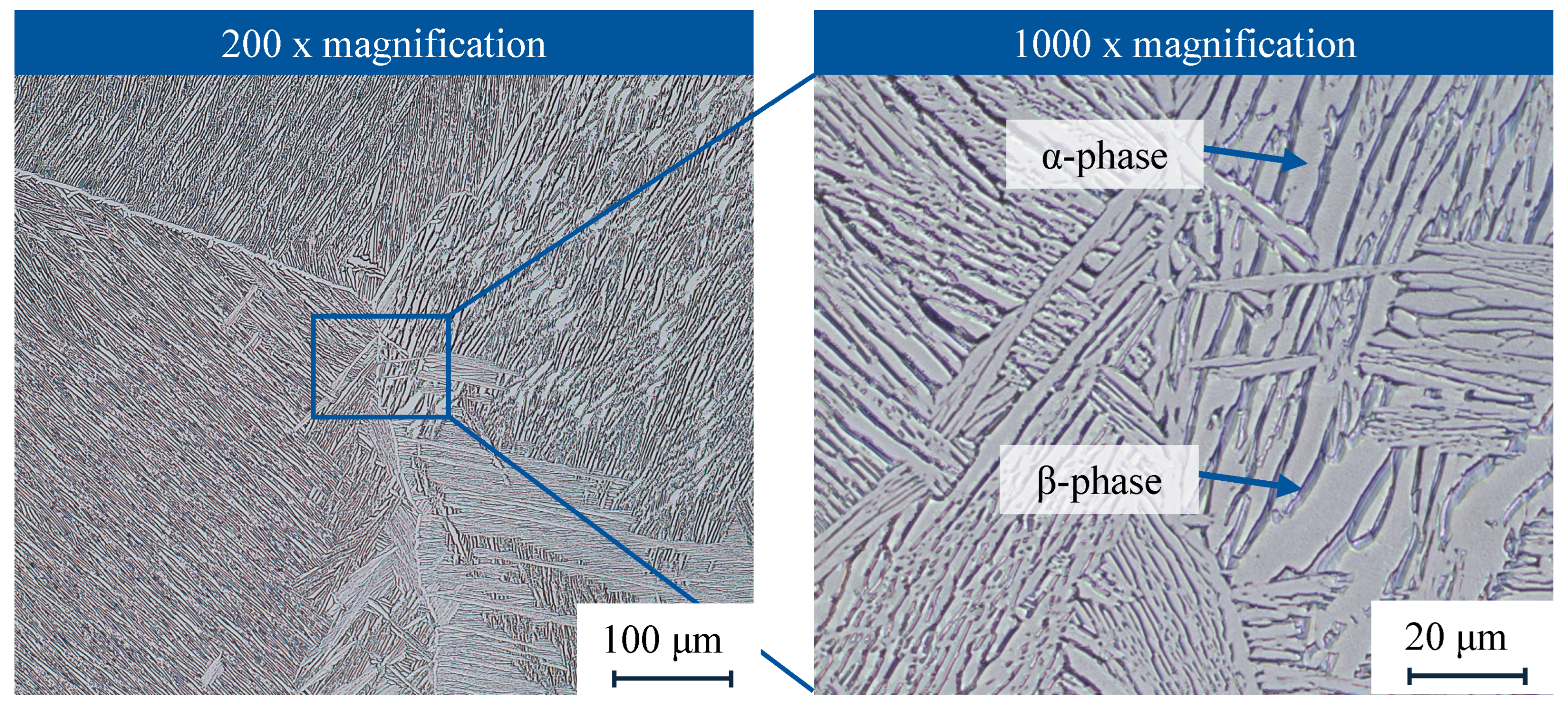
The Ti-6Al-4V workpiece, Grade 5 in the annealed condition, was prepared in the form of a block with dimensions of 165 × 165 × 150 mm. The chemical composition was determined via spectral analysis and is summarized in Table 1. The microstructure of the material is shown in Figure 2. It shows a typical Widmanstätten pattern with a homogeneous phase distribution. The structure of the  α -phase lamellae is interconnected to form a regular reticulated pattern. Alternating  β -phase plates are present between the lamellae. The hardness was measured at several points on the workpiece and was found to be 335 ± 3 HV.

2.2. Experimental Design and Procedure

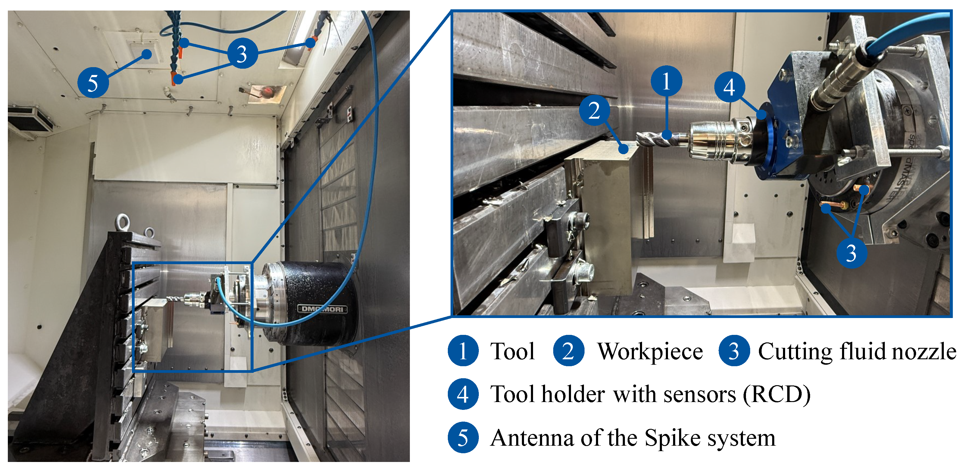
The wear and temperature measurement experiments were conducted on a NHX 5000 CNC horizontal machining center from DMG MORI AG, Bielefeld, Germany. The machine is equipped with a  P m a x = 37 kW spindle, a maximum rotational speed of  n m a x = 15,000 rpm, and a maximum torque of  M t , m a x = 250 Nm. It is controlled via the M730UM control system with the CELOS interface. An angular table was mounted on the machine bed, and the workpiece was securely clamped using four clamping claws, as illustrated in Figure 3. The investigated process was peripheral milling performed under a fixed set of cutting parameters, which are summarized in Table 2. The selected parameter combination corresponds to semi-finishing operations and is based on recommendations provided by the tool manufacturer. However, to accelerate tool wear due to limited workpiece material availability, the axial depth of cut  a p was reduced from the recommended 16 mm to 8 mm, while the radial depth of cut  a e was increased from 3 mm to 5 mm.
Flood cooling was used to supply the cutting fluid. On the machine side, three nozzles were directed at the machined surface of the workpiece, while four additional nozzles on the spindle were aimed at the cutting tool. This arrangement ensured sufficient and uniform flood cooling of the cutting zone. Three distinctly different cutting fluids from Rhenus Lub GmbH (Mönchengladbach, Germany) were tested: a mineral oil-based cutting oil, a water-emulsifiable ester-based emulsion, and a fully synthetic, oil-free water-soluble fluid. The properties of these fluids are summarized in Table 3. The emulsion and oil-free fluid were mixed at a concentration of 8% while the cutting oil had a viscosity of  ν = 11 mm2/s at 40 °C.
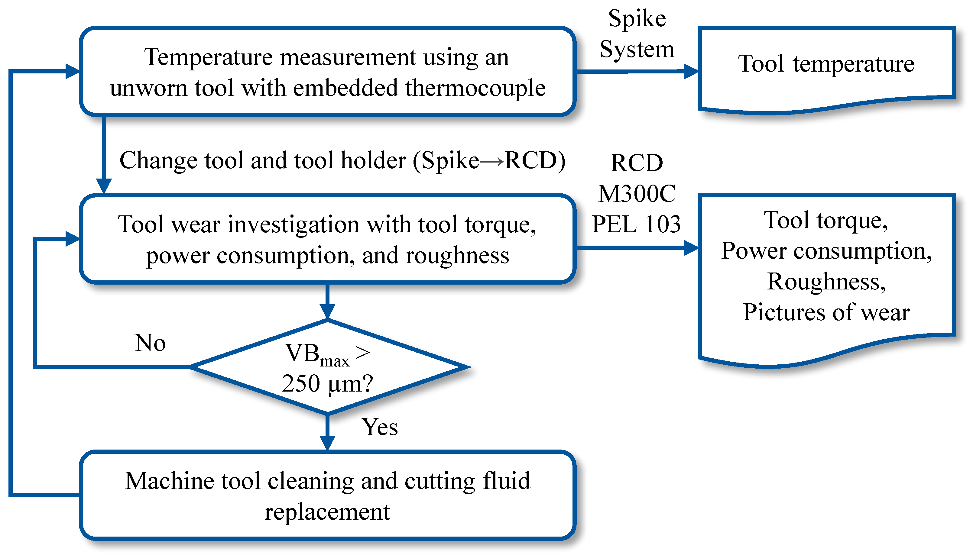
During the experiments, the tool temperature was first measured under dry conditions and flood cooling with different cutting fluids. The temperature measurement under dry conditions served as a reference, allowing the cooling effectiveness of the different cutting fluids to be quantified based on the temperature reduction. The temperature data were transmitted wirelessly via the Spike system to the antenna, as illustrated in Figure 3, item 5. Temperature measurements were performed only with unworn tools, while the tool wear tests were carried out using tools without embedded thermocouples. This was performed to avoid potential influences on the wear results, as the temperature measurement hole could affect the stiffness of the tool, potentially altering its wear behavior. Each temperature test was repeated three times to ensure statistical repeatability.
For the wear investigation, the tool was mounted on a tool holder equipped with a rotating dynamometer RCD 9171A from Kistler Instrumente AG, Winterthur, Schweiz, which measured torque and cutting forces. The tool holder featured an HSK63 interface. During the experiments, the torque on the tool was recorded to observe the influence of tool wear and cutting fluid on the tool torque. Tool wear was evaluated after a defined feed path length using a digital microscope VHX-7000 from Keyence, Osaka, Japan. Surface roughness was measured on the side surface of the workpiece, in the feed direction, using a mobile roughness measuring device MarSurf M 300 from Mahr GmbH, Göttingen, Germany.
Wear tests were continued until either the maximum flank wear land VBmax exceeded 250  μ m or severe cutting edge fracture occurred. The wear criterion of 250  μ m was selected based on preliminary tests, which showed that tool wear enters a progressive increase phase at this point, accompanied by a significant rise in cutting forces.
Additionally, the power consumption of the machine tool was continuously monitored throughout the experiments using PEL 103 power recorders from Chauvin Arnoux GmbH, Kehl, Germany, in order to examine the effect of cutting fluid on machining power requirements.
To provide a clear overview of the entire experiment, the complete experimental procedure, including the sensors used and the types of process data recorded, is summarized in a flowchart shown in Figure 4. Between each cutting fluid test, the machine tool was thoroughly flushed with system cleaner and water to ensure proper cleaning.

3. Model Setup for Process and Temperature Simulation

Force measurements serve to evaluate the lubrication performance of cutting fluids in terms of mechanical tool loads. Temperature measurements complement this by providing insights into the cooling effectiveness of the fluids during machining. However, while temperature data can reflect the overall cooling performance, it does not directly indicate the heat partition into the tool or the amount of heat dissipated by the cutting fluid. These factors need to be estimated by numerical simulation. To address this, the present study introduces two simulation approaches. The first is a thermal model, which uses experimentally measured temperature data to inversely estimate the heat input into the tool and the convective cooling coefficient of the cutting fluid. The second approach involves computational fluid dynamics (CFD) to simulate local flow behavior, offering a more detailed understanding of the cooling mechanisms.

3.1. Simulation Approach for Tool Temperature Prediction

The purpose of the thermal simulation is to evaluate the heat input into the cutting tool and the cooling effectiveness of the cutting fluid. It also provides insight into the temperature distribution within the tool. The proposed simulation approach builds on previous research by the authors [16]. Figure 5 shows the boundary conditions defined in the simulation model. The heat source is applied at the tool–workpiece contact surface, identified from microscopic images of the tool. Due to the rotational motion of the tool during machining, the heat flux is not applied simultaneously to all the cutting edges, but sequentially, based on their engagement with the workpiece. The engagement time of each cutting edge is determined by the cutting parameters. To improve computational efficiency, the heat flux on each engaged cutting edge is assumed to be uniform and constant along the contact zone during engagement, as shown in Figure 5. All tool surfaces outside the chip contact zone are defined as convective boundaries to represent heat loss to the environment. Under dry cutting conditions, where convection is negligible, these surfaces are treated as adiabatic boundaries.
The simulations were performed using ABAQUS 2021, a commercial finite element software. An implicit heat transfer solver was applied. The mesh consisted of tetrahedral elements (DC3D4) with a mesh size of 0.1 mm. The thermophysical properties of the cutting tool used in the simulation are summarized in Table 4 and were obtained from a previous study. The data were provided by the tool manufacturer and supplemented by pre-test measurements [17]. A process time of 26 s was simulated, corresponding to the cutting duration in the temperature measurement experiments. The average computation time per simulation was approximately 20 min, using 16 parallel 2.3 GHz CPU cores.
In this study, the temperature measured by the thermocouple served as a reference. The simulated heat input into the tool was iteratively adjusted until the temperature at the measurement location in the simulation matched the experimental value. The accuracy of this method depends on the precise positioning of the measurement hole. To ensure the reliability of the simulation, the tool was sectioned after the experiment, and the hole position was verified.
Using a single measurement point to represent the overall temperature distribution within the tool is not sufficient. However, due to experimental limitations, only one measurement point was feasible in this study. As a result, the estimated heat input into the tool is associated with uncertainty. Further validation through additional experiments and multi-point temperature measurements is planned for future work.

3.2. Process Simulation Considering Cutting Fluid Effects

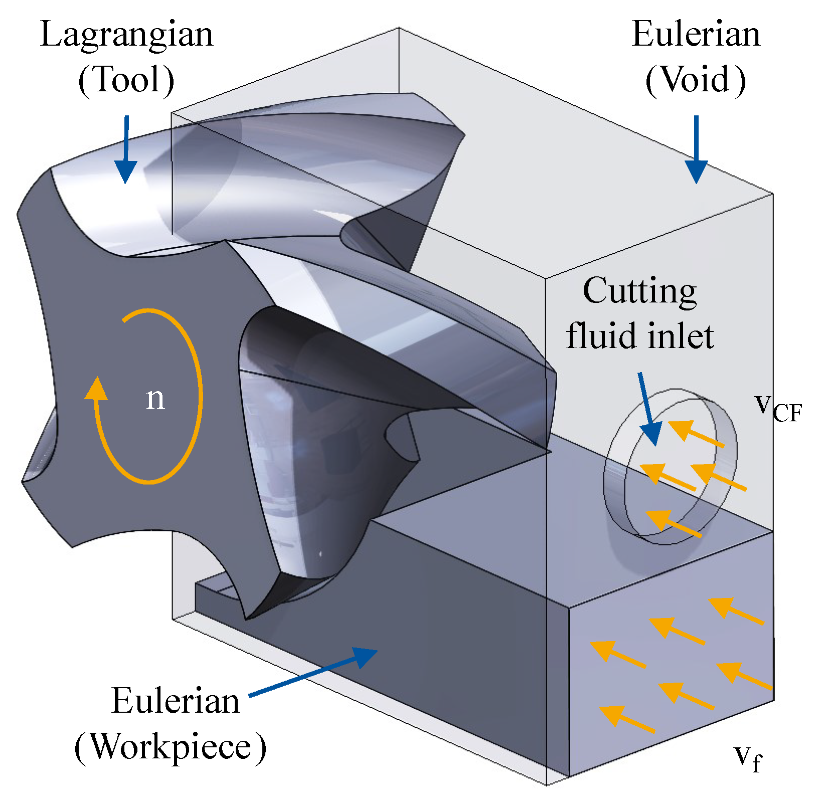
The convective cooling efficiency of a cutting fluid depends on its thermophysical properties and its flow velocity in the cutting zone. High rotational speeds of the cutting tool and chip formation can significantly disrupt fluid flow in this region. This study uses a Coupled Eulerian–Lagrangian (CEL) simulation approach to analyze cutting fluid behavior during milling. The CEL method is a built-in function of the commercial finite element software ABAQUS and is widely used in machining simulations. It avoids mesh distortion, which is a frequent issue in Lagrangian-based models, by applying Eulerian mesh mapping. The method can simulate both solid and fluid phases, making it suitable for modeling cutting fluid flow in complex machining processes. Previous studies have successfully applied CEL in orthogonal cutting, turning, and circular sawing [18]. In this study, CEL is extended to milling to investigate cutting fluid flow dynamics and their interaction with the cutting process. The existing simulation results demonstrate that CEL effectively captures the influence of the cutting fluid on chip formation and preserves realistic geometric boundaries, improving the accuracy of the simulated flow field. However, the method lacks resolution in modeling boundary layer behavior on solid surfaces, which limits its applicability for thermal analysis [19]. Consequently, CEL cannot be used to evaluate tool temperature or to quantify convective heat transfer. Its use in this context is therefore limited to the qualitative analysis of cutting fluid flow during the cutting process [19].
Figure 6 illustrates the model setup used in the process simulation. The tool was defined using a Lagrangian mesh, while the workpiece and cutting fluid were discretized within an Eulerian domain. The tool was modeled as a rigid body, and therefore tool wear was not considered in the simulation. During the cutting process, the tool performed rotational movement only, while the feed motion was applied through translational movement of the workpiece. To model the plastic behavior of the workpiece material, the Johnson–Cook material model was applied. It is a widely used constitutive model in machining simulations, as it accounts for the effects of strain hardening, strain rate sensitivity, and thermal softening. The flow stress is calculated using the following expression [20]:
σ = A + B · ε n · 1 + C · ln ε ˙ ε ˙ 0 · 1 T T 0 T m T 0 m
where A, B, and n represent the strain hardening behavior, C accounts for strain rate sensitivity, and the last term describes thermal softening as the temperature approaches the melting point  T m . The reference values  ε ˙ and  T 0 are the initial strain rate and room temperature, respectively. This formulation allows realistic prediction of material behavior under high strain rates and elevated temperatures, as commonly observed in cutting processes. According to the theory of hyperelasticity, the flow stress drops sharply once the criterion for damage initiation is reached. Damage initiation was modeled using the Johnson–Cook damage model, which estimates the strain at failure  ε f based on stress triaxiality, strain rate, and temperature [21]:
ε f = D 1 + D 2 · exp D 3 · σ m σ e q · 1 + D 4 · ln ε ˙ ε ˙ 0 · 1 + D 5 · T T 0 T m T 0 m
In this equation,  σ m / σ e q represents the stress triaxiality, which affects void growth and failure. The constants  D 1 to  D 5 are material-specific and must be experimentally calibrated.
In addition to the material model, friction also plays a crucial role in cutting simulation. It influences the deformation in the secondary shear zone, as well as chip thickness, chip flow direction, cutting force, and temperature [22]. This study used the temperature-dependent friction model developed by Puls et al. [23]. The coefficient of friction is defined by the following equation:
μ = μ 0 T < T f μ 0 · 1 T T f T m T f m f T T f
This model describes how friction decreases with increasing temperature. Below a transition temperature  T f , the coefficient remains constant at  μ 0 . Above  T f , friction progressively declines as the temperature approaches the material’s melting point  T m , controlled by the exponent  m f . This behavior represents physical phenomena in cutting, where high temperatures soften the contact surface, reducing friction. This study did not include calibration of the material or friction models. Instead, the model parameters were adopted directly from Klocke et al. [24]. Table 5 summarizes the material and friction model parameters used in this work.
The CEL model defined the fluid behavior using the continuity, momentum, and energy equations. The cutting fluid was simplified as an incompressible Newtonian fluid, while turbulence, evaporation, and air–liquid interactions were neglected within the fluid domain. ABAQUS used the Mie–Grüneisen equation of state to solve the governing equations. For low-velocity flows, the equation was simplified as follows:
p = ρ 0 · c 0 2 · 1 ρ 0 ρ
where  c 0 denotes the speed of sound in the fluid [25]. Emulsion and oil-free fluids were approximated as water due to the low concentration (8%). The physical properties used for simulating cutting oil and water-based fluids are summarized in Table 6. The data were obtained partly from manufacturer specifications and partly from literature sources [26].
A minimum mesh size of 0.1 mm was used in the cutting zone based on mesh sensitivity analysis. The simulation time for half a tool revolution was approximately five days using 46 parallel 2.3 GHz CPU cores.

4. Experimental and Simulation Results and Discussion

Under identical cutting parameters, different cutting fluids result in varying tool loads and tool life. The first subsection presents and discusses the results of the tool life experiments, including wear progression, chip morphology, torque development, and changes in surface roughness. It also compares the power consumption of the machine tool under different cutting fluid conditions. Temperature measurements were carried out using unworn tools. The results clearly indicate significant differences in cooling effectiveness between cutting oil and water-based fluids.
The second subsection focuses on the thermal simulation results, showing the evolution of the tool temperature field. This is followed by a process simulation-based analysis of fluid flow behavior, offering a theoretical explanation for the observed differences in cooling effectiveness across the tested cutting fluids.

4.1. Evaluation and Interpretation of Experimental Results

During the tool wear tests, the maximum width of the flank wear land (VBmax) was measured using a Keyence microscope at predefined feed travel intervals. Figure 7 illustrates the wear progression under different cutting fluid conditions, with dry cutting used as the reference.
Under dry conditions, tool wear progressed rapidly. Within a feed travel of less than  l f = 1 m, VBmax already reached 287.5  μ m. In contrast, the use of cutting fluids significantly extended tool life. All three tested fluids followed a similar trend. After an initial wear phase, wear remained relatively stable over a certain feed length. Once this range was exceeded, wear increased sharply, showing a progressive trend. Distinct differences were observed among the cutting fluids. The fully synthetic oil-free fluid resulted in the shortest tool life, with severe notch wear observed at a feed travel length of approximately  l f = 11 m. Its wear behavior in the early stage was comparable to that of the emulsion but began to rise steeply after  l f = 4.95 m. In the case of cutting oil, tool wear remained lower than with water-based fluids during the initial phase. Up to  l f = 4.95 m, wear increased only slightly, but beyond this point it accelerated and entered a progressive phase. The final tool life reached  l f = 12.21 m, slightly outperforming the oil-free fluid. The emulsion led to the best tool life. Initial wear levels were similar to those seen with the oil-free fluid but remained nearly constant up to  l f = 12.21 m. Beyond this, wear also increased, although at a much slower rate than with the other two fluids.
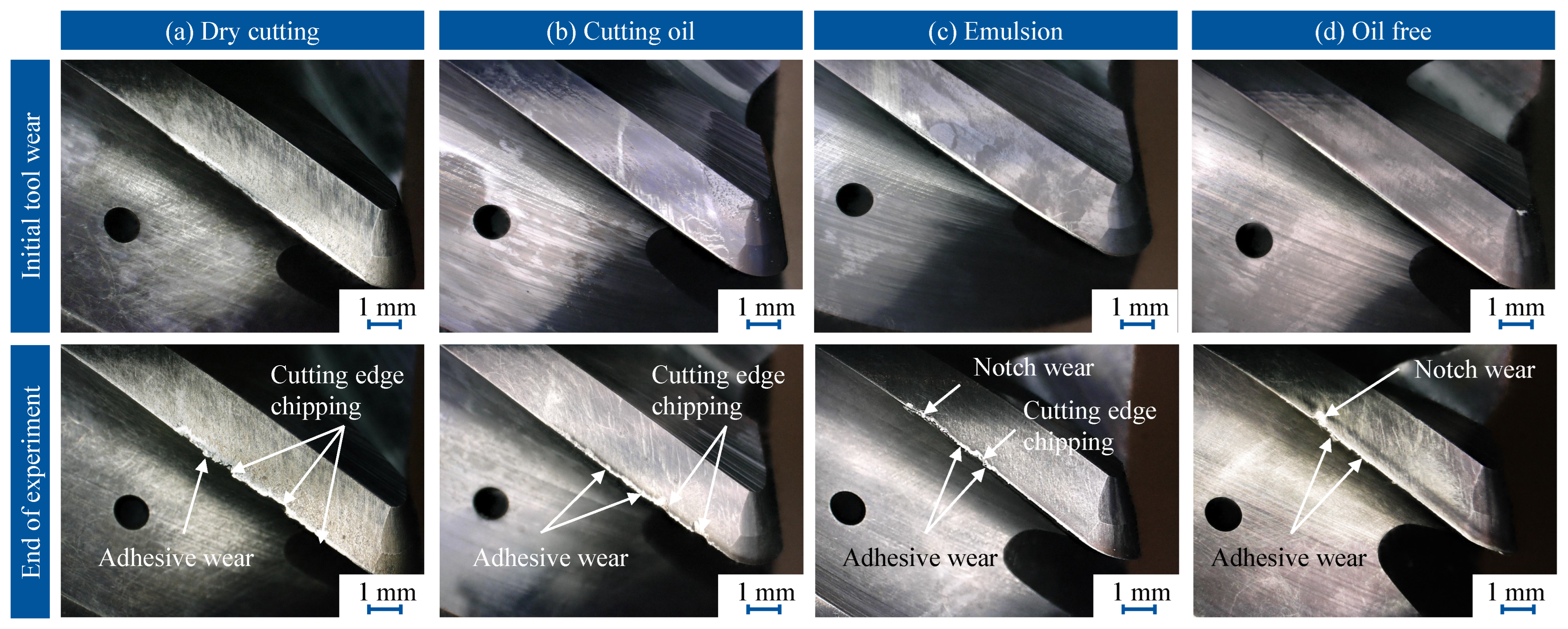
The differences in tool wear were attributed to the distinct cooling and lubricating properties, as well as the chemical compositions, of the fluids. To better understand the wear mechanisms, Figure 8 presents microscopic images of tool flank wear at the beginning and end of tool life. Initially, all tools exhibited a uniform wear pattern along the cutting edge. However, under dry conditions, built-up edge and adhesive wear were clearly visible. In contrast, the tool used with cutting oil showed the lowest initial wear. Minimal adhesive wear was observed with emulsion and oil-free fluids. At the end of tool life, cutting edge fracture was observed under all conditions. Under dry cutting, severe edge chipping was evident along the entire cutting edge, frequently accompanied by material adhesion. These findings indicate adhesive wear as the dominant wear mechanism in dry machining, with excessive thermal and mechanical loads leading to rapid fracture.
Cutting oil significantly reduced adhesive wear, but edge chipping still occurred, particularly near the front face, where thermal loads were highest. Although adhesive wear remained visible near the tool–workpiece entry zone (associated with axial depth of cut  a p ). Notch wear was less pronounced with cutting oil. In contrast, under water-based fluids (emulsion and oil-free cutting fluid), no significant edge chipping was observed near the tool front face. However, notch wear and adhesive wear were clearly present. This is likely due to the superior cooling performance of water-based fluids, which effectively reduce overall thermal load and suppress edge chipping. However, intense localized cooling near the entry zone reduces the workpiece temperature and, consequently, thermal softening. This raises the mechanical strength of the material, accelerating notch wear.
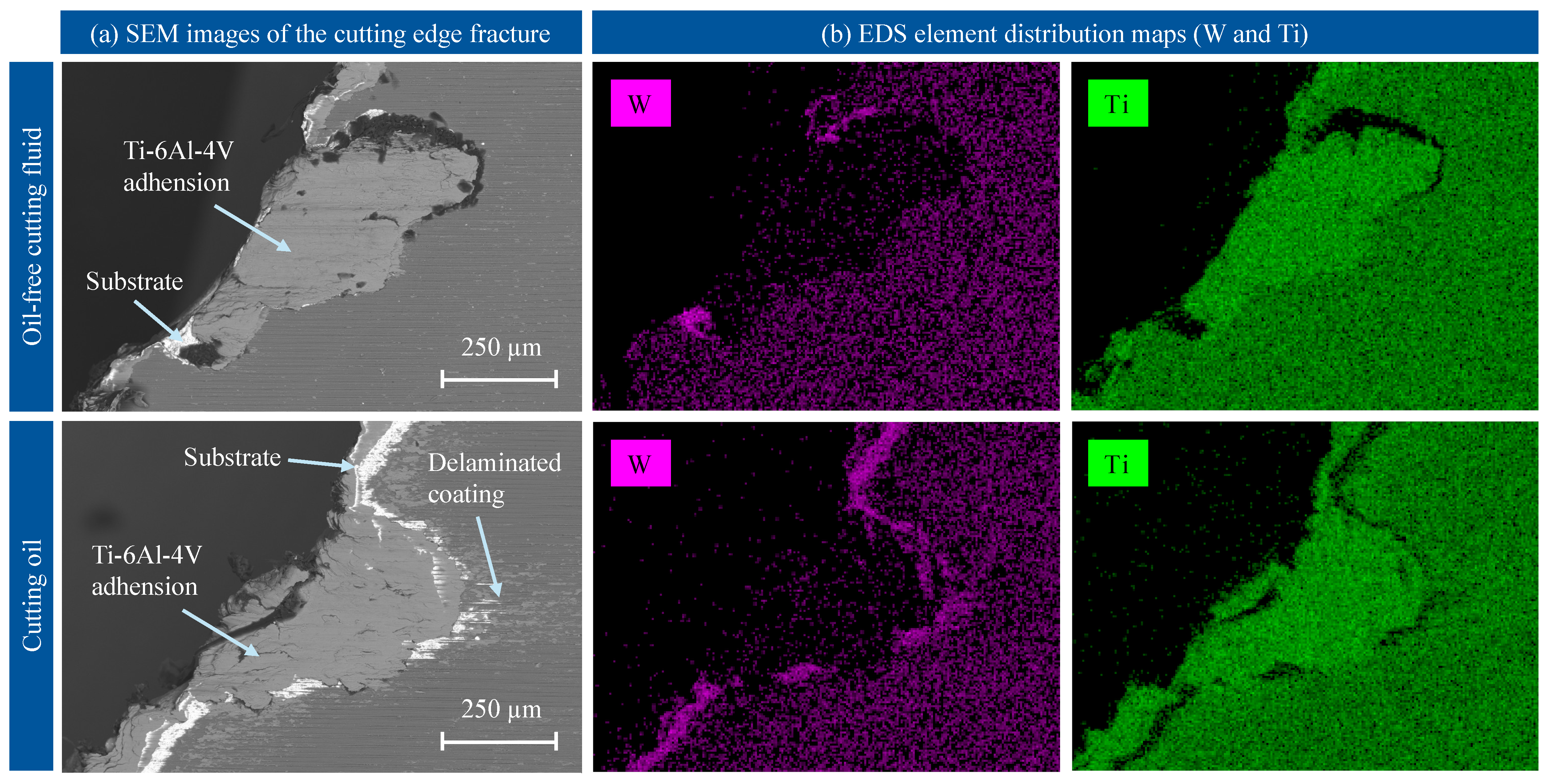
Figure 9 further analyzes the microstructure of the fracture zones using Scanning Electron Microscopy (SEM), shown in Figure 9a, and examines the element distribution of Ti from the workpiece and W from the tool substrate using Energy-Dispersive X-ray Spectroscopy (EDS), shown in Figure 9b. The results indicate that, regardless of whether cutting oil or oil-free fluid was used, significant adhesion occurred near the fracture regions and damaged coating areas. No significant adhesion was observed on intact coating areas, confirming that the tool coating effectively prevents adhesive wear.
Under oil-free fluid, the fracture boundary appeared sharp, and the coating remained largely intact near the boundary. In contrast, under cutting oil, coating delamination was observed at the fracture boundary. This phenomenon is attributed to the combined effects of localized thermal softening and high mechanical stress. Although cutting oil reduced overall adhesive wear, its limited cooling capability resulted in sustained localized high temperatures near the cutting edge. This thermal stress, combined with mechanical loading during cutting, weakened the bond between the coating and the substrate, promoting delamination. Moreover, the reduced convective cooling under cutting oil conditions may have led to a more pronounced thermal gradient at the coating–substrate interface, further accelerating coating failure.
In summary, analysis of the tool wear images indicates that when machining Ti-6Al-4V with carbide tools, the primary wear mechanisms are adhesive wear and edge chipping, both driven by high thermomechanical loads at the cutting edge. Cutting oil can effectively reduce adhesive wear but is insufficient to prevent edge chipping due to its limited cooling performance. In contrast, water-based fluids lower the tool temperature and reduce thermal load, thereby minimizing edge chipping. However, they tend to accelerate notch wear, which becomes the dominant failure mode under these conditions.
The cutting fluid and the tool wear condition both influence the thermomechanical loads acting on the tool, which in turn affect chip formation. Figure 10 shows the chip morphology at the beginning of the experiment and at the end of tool life. Initially, the chips exhibited similar shapes across all conditions, forming slender, curled spirals. However, under dry cutting, elevated temperatures in the cutting zone caused chip welding, indicating possible chip adhesion and recutting events during machining. As tool wear progressed, the chip morphology changed significantly. In the dry cutting condition, further temperature rise led to extensive chip welding. This not only accelerated tool wear but also increased the risk of damaging the workpiece surface, thereby compromising surface quality.
At the end of tool life, chips produced under cutting oil and water-based fluids appeared flatter with reduced curvature and developed a distinct lamellar structure. This transformation is attributed to the enlarged cutting edge radius caused by wear, which increases strain rate and temperature in the cutting zone. The resulting flatter chip geometry reduces the rakeface–chip angle, impeding cutting fluid access to the cutting zone and diminishing its cooling and lubricating performance. This condition correlates with the observed transition from stable to progressive tool wear.
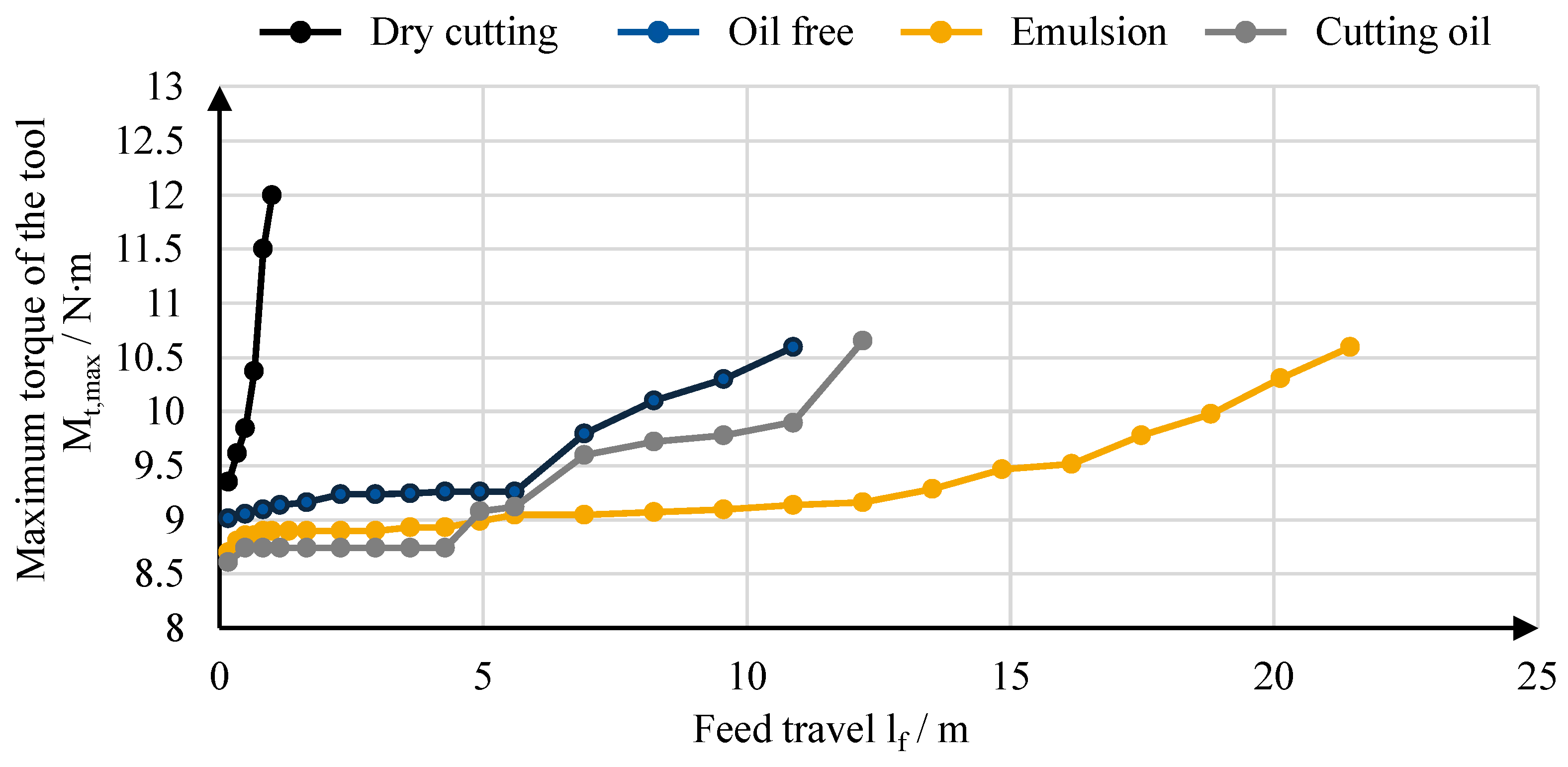
Tool wear and the increased tool–chip contact length contributed to a rise in cutting torque. Figure 11 presents the maximum torque values recorded by the RCD sensor. The results show a trend that closely mirrors the progression of tool wear. As wear increased, the torque demand rose accordingly. In the early stages of the experiment, torque values under cutting fluid conditions were slightly lower than those observed in dry cutting. Among the fluids tested, emulsion and cutting oil yielded slightly lower torque compared to the oil-free fluid due to the lubricating properties of the oil-based components. However, no significant difference was found between the emulsion and cutting oil. This observation suggests that the cutting oil did not provide any additional lubrication benefits over the emulsion.
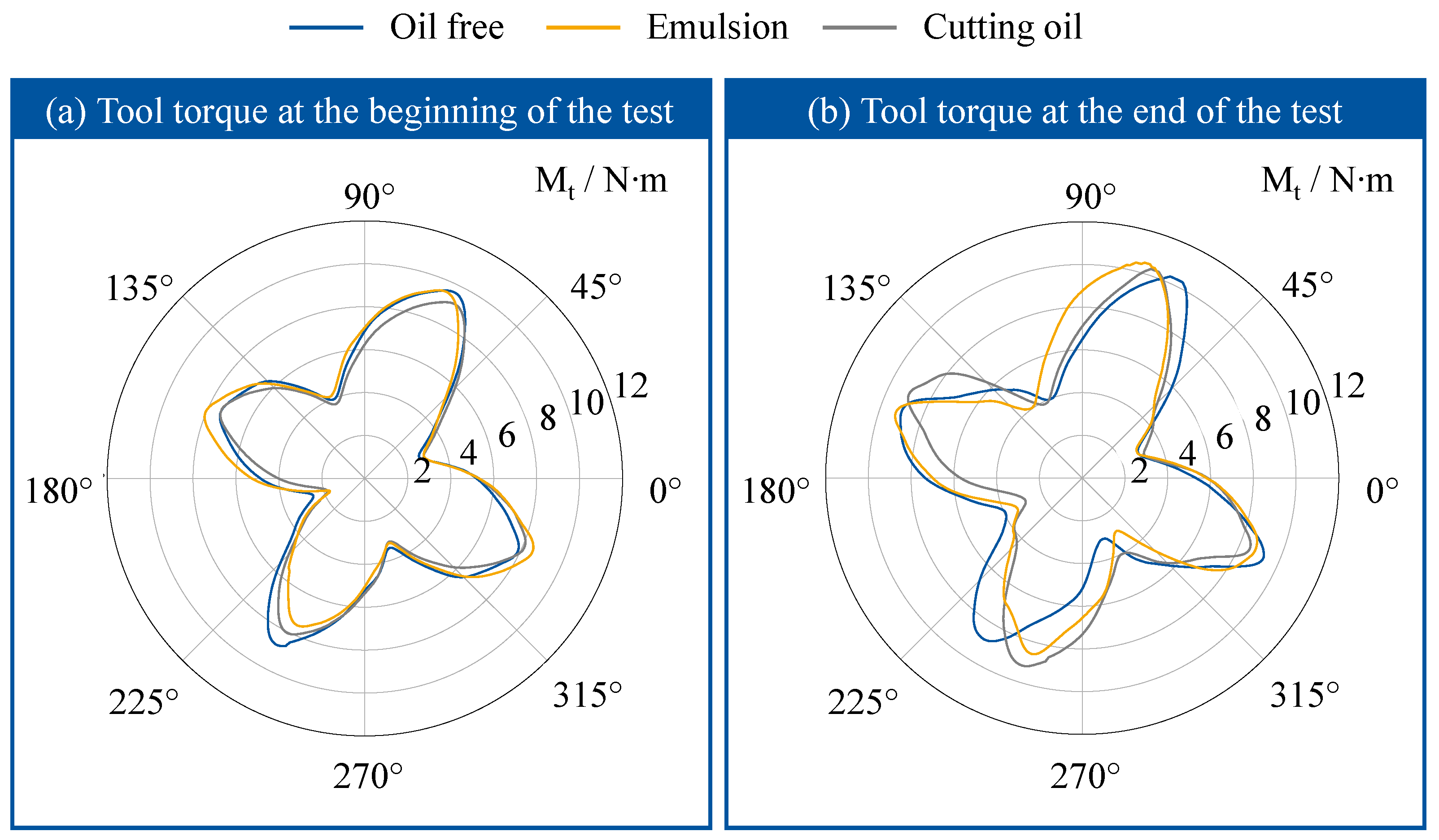
To better visualize the influence of cutting fluids on tool torque, Figure 12 shows a polar diagram of the torque profile over one full rotation of the cutting tool. The angular position in the diagram corresponds to the tool rotation angle, while the radial distance represents the torque magnitude. Each curve reflects the average torque profile over the first 50 tool revolutions.
Figure 12a shows the torque profile at the beginning of the experiment. The engagement of the four cutting edges is clearly visible. The torque values varied between the cutting edges, and the phase difference between them was not exactly 90°. This is due to the symmetric geometry of the tool. The four cutting edges were intentionally offset by approximately 3° to suppress high-frequency vibrations. At the beginning of the tool wear tests, all three cutting fluids produced nearly identical torque profiles, indicating that the lubricating effects had little impact on mechanical tool loads when the tool was unworn.
Figure 12b presents the torque profile at the end of tool life. Notch wear had altered the engagement conditions of the cutting edges, leading to visible phase shifts between the torque profiles of the three fluids. For both the emulsion and cutting oil, the presence of multiple edge chippings caused irregular engagement, resulting in torque fluctuations and pronounced waveform patterns in the polar diagram.
Tool wear and temperature changes in the cutting zone can influence surface roughness by altering the thermomechanical loads on the workpiece surface. Figure 13 presents the arithmetic mean surface roughness  R a measured during the experiment using a portable roughness tester. Measurements were taken along the feed direction at different locations, and the average values were recorded. The measurement values fluctuated within a range of approximately ±8%. The results show significant variations in surface roughness within the first 3 m of feed travel. This fluctuation is attributed to rapid changes in tool microgeometry during the initial wear phase. Once wear stabilized, surface roughness values became more consistent.
At the beginning of the test, cutting oil produced a noticeably lower surface roughness compared to the other cutting fluids. However, with increasing feed travel, the surface roughness for all three fluids converged to an average value of approximately  R a = 0.5  μ m. Unlike the trend observed for tool torque, arithmetic average surface roughness  R a did not increase with progressive tool wear.
One possible explanation is that surface roughness is not linearly correlated with cutting forces or the progression of tool wear. This indicates a nonlinear relationship between  R a and wear development, in which further tool wear does not necessarily result in increased surface roughness. A similar observation has been reported in [27]. Additionally, dominant wear mechanisms such as adhesion and chipping affect surface topography in ways that are not fully captured by  R a alone.
In this study, surface roughness was assessed using  R a , in accordance with common industrial practice. Parameters such as  R z were not recorded. The results therefore suggest that future studies should include  R z to enable a more comprehensive evaluation of surface quality.
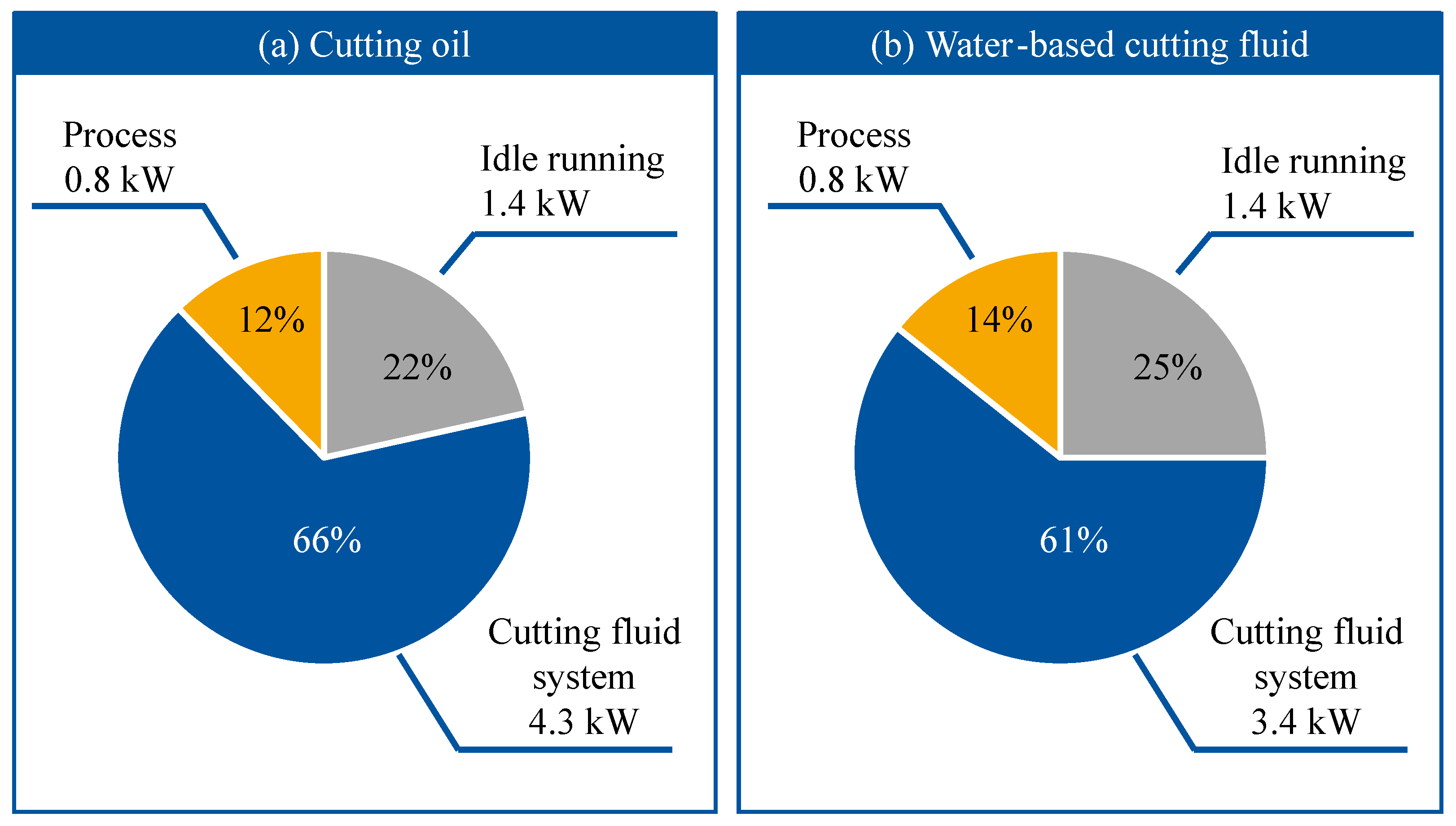
Despite the benefits of cutting fluids, their supply systems contribute to additional energy consumption and thus increase overall production costs. A study by Brecher et al. [28] showed that cutting fluid supply systems can account for more than 45% of the total energy consumption in modern machine tools. The use of high-viscosity fluids such as cutting oil can further raise energy demand. To assess this effect, the present study monitored the energy consumption during the tool wear tests. Figure 14 shows the energy distribution for cutting oil and water-based fluids, separating the contributions from the machine base load, the cutting process, and the cutting fluid supply system.
The results in Figure 14 show that the base power consumption of the machine tool was approximately 1.4 kW, while the power demand of the cutting process remained stable at around 0.8 kW. The most significant difference in total energy consumption arose from the cutting fluid supply system. When using cutting oil, as shown in Figure 14a, the cutting fluid supply system consumed about 4.3 kW, accounting for 66% of total energy consumption. In contrast, water-based fluids required less pumping power due to their lower viscosity. As shown in Figure 14b, the energy consumption of the cutting fluid supply system dropped to around 3.4 kW. These findings underline that the cutting fluid supply system represents the largest share of machine tool energy use.
In light of rising energy prices and stricter industrial carbon regulations, reducing the energy consumption associated with cutting fluid delivery has become a central aspect of coolant strategy optimization. The supply system used in this study operates with a bypass mechanism that continuously delivers cutting fluid at the maximum flow rate, which is not energy efficient. In contrast, frequency-controlled pumps allow for demand-based fluid delivery. Leading machine tool manufacturers have reported that conventional cooling systems can account for up to 70% of a machine’s total power consumption. By implementing frequency-controlled pumps combined with intelligent software control, overall energy usage can be reduced by more than 30% [29]. This represents an important focus for future research.
Beyond pump control, additional efficiency gains can be achieved through targeted internal cutting fluid supply. Internal channels allow precise fluid delivery directly to the cutting zone, improving heat dissipation and minimizing fluid waste. When combined with high-pressure delivery, this method enhances chip evacuation, reduces thermal stress on the tool, and contributes to longer tool life and better surface quality. Furthermore, by supplying coolant only where and when it is needed, internal high-pressure systems reduce both fluid consumption and pumping effort. This not only improves energy efficiency but also supports environmentally sustainable machining practices. The integration of targeted and high-pressure internal cooling thus represents a promising avenue for future advancements in cutting fluid system design.
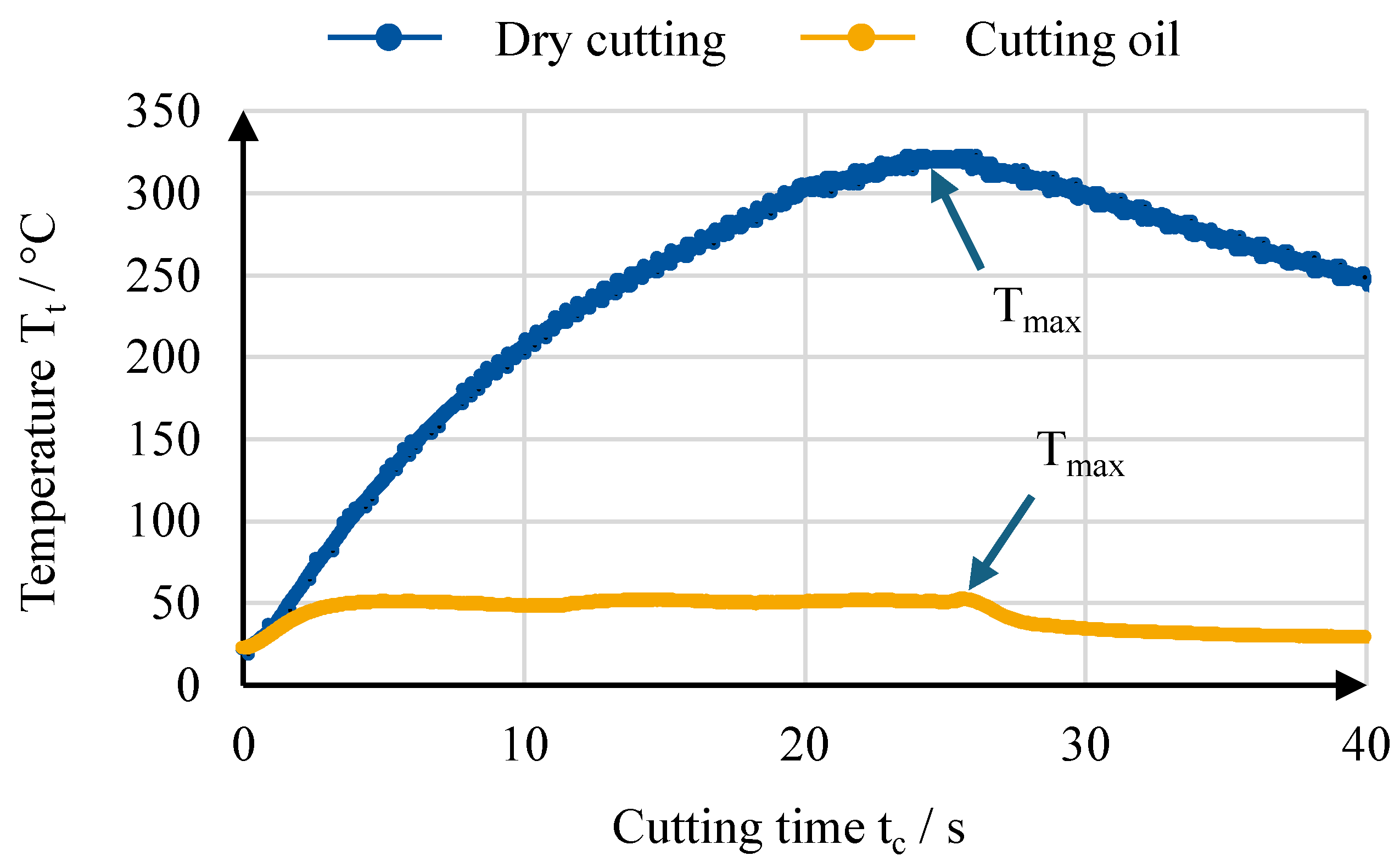
Based on the wear results, it was assumed that cutting oil provides a lower cooling effect than water-based fluids. To validate this hypothesis, the temperature measurements are analyzed in the following section. Figure 15 shows the temperature data recorded during milling with a total feed travel  l f = 165 mm using an unworn tool.
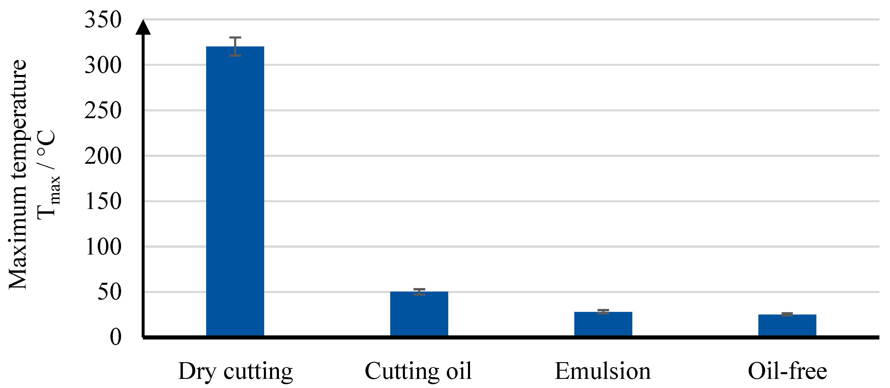
Under dry cutting conditions, the tool temperature continuously increased, exceeding 300 °C at the measurement point. In contrast, with cutting oil, the temperature rose to approximately 50 °C and quickly stabilized. These results confirm the feasibility of using an embedded thermocouple for in-process temperature monitoring and highlight the cooling effectiveness of cutting fluids. Furthermore, the consistent temperature under fluid-assisted cutting indicates a well-designed nozzle configuration that ensures uniform cooling throughout the cutting process. For a more direct comparison of temperature performance across the different fluids, Figure 16 summarizes the maximum tool temperatures measured under each condition.
The difference in maximum temperature at the thermocouple measurement point between cutting oil and water-based fluids is clearly shown in Figure 16. When using cutting oil, the tool temperature stabilized at approximately 50 °C. In contrast, water-based fluids further reduced the temperature to around 28 °C. No significant temperature difference was observed between the emulsion and the oil-free cutting fluid, indicating that both provided comparable and sufficient cooling. These results further confirm that water-based fluids offer superior convective cooling performance compared to cutting oil.

4.2. Evaluation and Interpretation of Simulation Results

Based on the experimental findings, simulations were carried out to gain a deeper understanding of the physical mechanisms underlying cutting fluid effectiveness. This subsection presents the results of tool temperature distribution and cutting fluid flow behavior simulated during the cutting process.
The first simulation approach involved thermal modeling of the entire cutting. The model setup is described in detail in Section 3.1. For dry cutting, convective cooling was assumed to be negligible. The heat input at the tool–chip contact zone was iteratively adjusted until the simulated temperature at the sensor location matched the measured value. For conditions involving cutting fluids, a uniform convective heat transfer was assumed across the tool surface. The heat input at the tool–chip interface was kept constant, assuming that it remains unaffected by the cutting fluid. By adjusting the convective heat transfer coefficient until the simulated temperature matched the measured sensor value, the average convective heat transfer coefficient for each cutting fluid was determined.
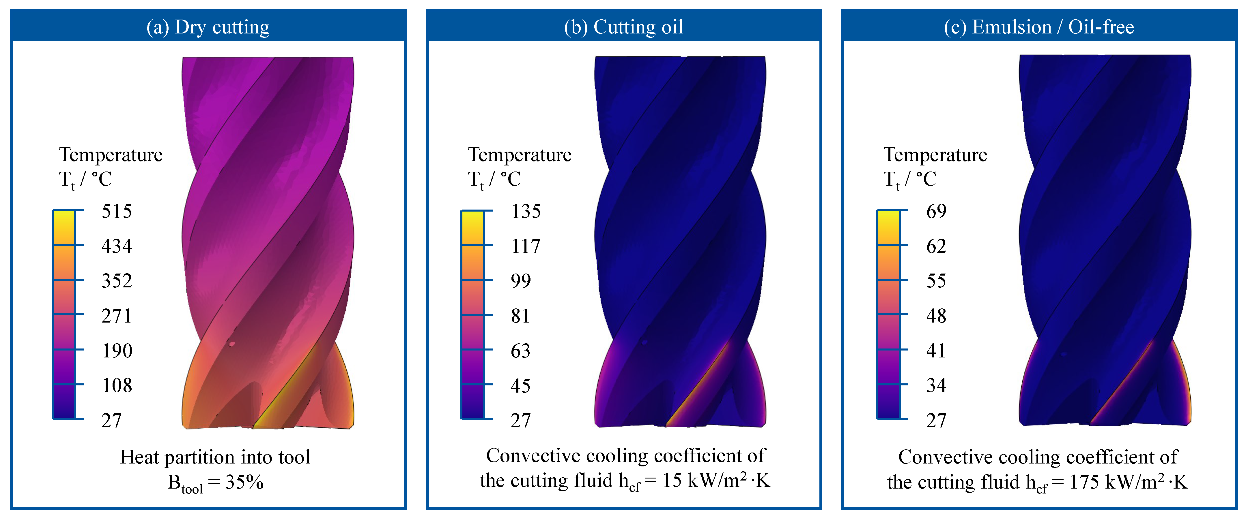
Figure 17 shows the inverse-calculated tool temperature distributions. Under dry cutting conditions, the overall tool temperature exceeded 100 °C, with the maximum temperature near the tool tip reaching approximately 515 °C, as shown in Figure 17a. The heat flux density at the tool–chip contact surface was approximately  q ˙ t o o l = 52.73 W/mm2, corresponding to roughly  B t o o l = 35% of the total process heat. This relatively high heat partition into the tool is partly due to the low thermal conductivity of Ti-6Al-4V, which promotes heat accumulation in the cutting zone, and partly due to the low cutting speed and feed rate typically used for titanium alloys, which limit heat dissipation via chips. Similar trends have also been reported in previous studies on steel machining [15].
With the use of cutting oil, the overall tool temperature was significantly reduced. As depicted in Figure 17b, the temperature around the tool tip increased noticeably within the cutting depth ( a p ) range, while the rest of the tool remained close to room temperature. The maximum tool temperature under cutting oil reached only 135 °C. The corresponding convective heat transfer coefficient determined from the simulation was  h c f = 15 kW/m2·K.
Compared to cutting oil, water-based fluids provided much higher convective cooling performance, reaching a heat transfer coefficient of  h c f = 175 kW/m2·K. As shown in Figure 17c, tool heating was confined to a small area near the cutting edge, with the rest of the tool fully cooled to ambient conditions. The maximum tool temperature under these conditions was only 69 °C. Although the measured temperature difference between cutting oil and water-based fluids was just 22 °C, the simulation results clearly demonstrate the superior convective cooling capacity of water-based fluids. The notably lower temperature near the tool tip further supports earlier wear observations, suggesting that cutting edge chipping near the tool front face is strongly linked to excessive thermal loads.
The effectiveness of a cutting fluid depends not only on its thermophysical properties but also on its ability to reach the cutting zone. In milling, the high rotational speed of the tool and the narrow gap between the tool and workpiece significantly limit cutting fluid access. To further investigate the flow behavior of different fluids, a fluid–structure coupled simulation was performed. The principles of this method are described in Section 3.2.
Figure 18 shows the simulated flow field streamlines and chip formation under different cutting fluids. For better visualization, the tool geometry is rendered semi-transparent. The simulation results reveal that, regardless of the cutting fluid type, a low-velocity stagnation zone forms near the jet impact point on the tool surface. This region, marked in dark blue, reduces the kinetic energy of the fluid and limits penetration into the cutting zone. Such effects can be mitigated by optimizing nozzle positioning or by adopting internal cutting fluid supply through the tool, both of which enhance fluid accessibility and heat dissipation. In Figure 18a, cutting oil results in significantly lower flow velocity within the narrow gap between the tool and workpiece, far below the jet inlet speed. In contrast, Figure 18b shows that water-based fluids maintain velocities only slightly below the inlet speed in the same region. This difference is mainly attributed to the higher viscosity of cutting oil, which hinders fluid flow in confined spaces and reduces its cooling performance.
While flow field simulations offer valuable insights into cutting fluid behavior, certain limitations must be acknowledged. The simulated tool torque was approximately 15% lower than the experimental measurements, likely due to discrepancies between the modeled and actual workpiece material properties. Additionally, the inlet fluid velocity used in the simulation was based on average flood cooling values. In practice, nozzle-induced energy losses may reduce the actual jet velocity. Therefore, the flow simulation results presented in this study should be interpreted qualitatively rather than quantitatively.

5. Conclusions and Outlook

This study conducted a comprehensive evaluation of three different cutting fluids, an emulsion, cutting oil, and a synthetic oil-free fluid, used in flood-cooled peripheral milling of Ti-6Al-4V. A dedicated experimental setup with embedded thermocouples enabled real-time temperature monitoring near the cutting edge, offering detailed insight into the thermal and tribological characteristics of the tool–workpiece interaction. The performance of each fluid was assessed through systematic measurements of tool wear, chip morphology, surface roughness, torque, and energy consumption. The key findings are summarized below.
  • Performance comparison of cutting fluids:Among the fluids tested, the emulsion delivered the most favorable performance. It achieved a tool life corresponding to a feed travel length of  l f = 12.21 m, which was approximately 200% longer than the  l f = 6.3 m and 6.1 m recorded for cutting oil and the oil-free fluid, respectively. This indicates that the emulsion provided the best balance of cooling and lubrication under the given process conditions.
  • Characteristics and limitations of cutting oil:Cutting oil showed good lubricating properties in the early phase of machining, effectively suppressing adhesive wear. However, its limited cooling capacity made it less effective in maintaining thermal stability, which contributed to localized edge chipping. This finding suggests that lubrication alone is insufficient to ensure tool stability during high thermal loading in titanium milling.
  • Thermal performance of water-based fluids:The water-based fluids, including the emulsion and oil-free coolant, significantly lowered the tool temperature to approximately 28 °C due to improved convective heat transfer. Simulations confirmed that their heat transfer coefficients were more than ten times higher than those of cutting oil. Nevertheless, the aggressive cooling at the tool entry zone increased notch wear, likely due to diminished thermal softening of the workpiece material, which elevated mechanical stresses on the cutting edge.
  • Energy consumption and supply system impact:The energy analysis identified the cutting fluid supply system as the primary contributor to total machine energy use. When using high-viscosity fluids such as cutting oil, the supply system accounted for up to 66% of the total energy consumption. These findings highlight the importance of selecting not only effective but also energy-efficient cooling systems.
  • Scope and applicability of the findings:The conclusions drawn in this study are based on a specific set of semi-finishing conditions and may not directly apply to other machining scenarios. Under different setups, such as higher cutting speeds, deeper depths of cut, or interrupted machining, the relative performance of the fluids may vary. Further research is recommended to validate these findings across a broader range of process conditions.
Future research should investigate a wider range of machining conditions and explore strategies such as internal cutting fluid delivery and adaptive cooling based on real-time temperature monitoring. In addition, integrating sustainable approaches, including minimum quantity lubrication and cryogenic cooling, in combination with predictive simulation models, offers promising potential for further process optimization.
To support environmentally conscious manufacturing, future work should also include a detailed assessment of the environmental impacts associated with different types of cutting fluids. This includes evaluating the potential ecological risks of fluid disposal, emissions during use, and the energy required for fluid preparation and circulation. Conducting life cycle assessments (LCAs) will be essential to quantify the environmental footprint of each coolant strategy and to balance it against process performance and economic efficiency. Such analyses will enable informed decisions on cutting fluid selection from both a technological and sustainability perspective. The continued development of numerical models and the design of corresponding validation experiments will remain also a key focus of future work.

Author Contributions

Conceptualization, H.L., M.M. and T.B.; Methodology, H.L., M.M. and T.B.; Software, H.L.; Validation, H.L.; Formal analysis, H.L.; Investigation, H.L.; Resources, H.L.; Data curation, H.L.; Writing—original draft, H.L.; Writing—review & editing, M.M. and T.B.; Visualization, H.L.; Supervision, M.M. and T.B.; Project administration, H.L., M.M. and T.B.; Funding acquisition, M.M. and T.B. All authors have read and agreed to the published version of the manuscript.

Funding

This research was funded by German Research Foundation (DFG) grant number 494849240.

Data Availability Statement

The original contributions presented in the study are included in the article, further inquiries can be directed to the corresponding author.

Acknowledgments

The authors gratefully acknowledge the support of the Industrial Working Group on Metalworking Fluids (IAK-KSS), with special thanks to Rhenus Lub GmbH & Co KG. Computational resources were provided by the NHR Center NHR4CES at RWTH Aachen University (project number p0020236), funded by the Federal Ministry of Education and Research and the participating state governments through GWK resolutions on national high-performance computing at universities (www.nhr-verein.de/unsere-partner, accessed on 1 February 2025).

Conflicts of Interest

The authors declare no conflict of interest.

Abbreviations

The following abbreviations are used in this manuscript:
CFDComputational Fluid Dynamics
CNCComputerized Numerical Control
EDMElectrical Discharge Machining
EDSEnergy-Dispersive X-ray Spectroscopy
EPExtreme Pressure
FEMFinite Element Method
RCDRotating Dynamometer
SEMScanning Electron Microscope

References

  1. Arrazola, P.J.; Garay, A.; Iriarte, L.M.; Armendia, M.; Marya, S.; Le Maître, F. Machinability of titanium alloys (Ti6Al4V and Ti555.3). J. Mater. Process. Technol. 2009, 209, 2223–2230. [Google Scholar] [CrossRef]
  2. Ezugwu, E.O.; Wang, Z.M. Titanium alloys and their machinability—A review. J. Mater. Process. Technol. 1997, 68, 262–274. [Google Scholar] [CrossRef]
  3. Pramanik, A. Problems and solutions in machining of titanium alloys. Int. J. Adv. Manuf. Technol. 2014, 70, 919–928. [Google Scholar] [CrossRef]
  4. Namb, M.; Paulo, D. Influence of Coolant in Machinability of Titanium Alloy (Ti-6Al-4V). J. Surf. Eng. Mater. Adv. Technol. 2011, 1, 9–14. [Google Scholar] [CrossRef]
  5. Sørby, K.; Tønnessen, K. High-pressure cooling of face-grooving operations in Ti6Al4V. Proc. Inst. Mech. Eng. Part B J. Eng. Manuf. 2006, 220, 1621–1627. [Google Scholar] [CrossRef]
  6. Su, Y.; He, N.; Li, L.; Li, X.L. An experimental investigation of effects of cooling/lubrication conditions on tool wear in high-speed end milling of Ti-6Al-4V. Wear 2006, 261, 760–766. [Google Scholar] [CrossRef]
  7. Klocke, F. Manufacturing Processes 1; Springer: Berlin/Heidelberg, Germany, 2011. [Google Scholar] [CrossRef]
  8. Vieira, J.M.; Machado, A.R.; Ezugwu, E.O. Performance of cutting fluids during face milling of steels. J. Mater. Process. Technol. 2001, 116, 244–251. [Google Scholar] [CrossRef]
  9. Mittal, R.K.; Kulkarni, S.S.; Singh, R.K. Effect of lubrication on machining response and dynamic instability in high-speed micromilling of Ti-6Al-4V. J. Manuf. Processes 2017, 28, 413–421. [Google Scholar] [CrossRef]
  10. Li, S.; Li, Y.; Li, Y.; Chen, D. Study of different cutting fluids effect on the coupling characteristics of milling noise-vibration and surface roughness of TA2 pure titanium. J. Manuf. Processes 2024, 118, 103–115. [Google Scholar] [CrossRef]
  11. Tanaka, R.; Hosokawa, A.; Furumoto, T.; Okada, M.; Ueda, T. Influence of cutting fluid on tool edge temperature in end milling titanium alloy. J. Adv. Mech. Des. Syst. Manuf. 2015, 9, JAMDSM0074. [Google Scholar] [CrossRef]
  12. Karaguzel, U.; Bakkal, M.; Budak, E. Modeling and Measurement of Cutting Temperatures in Milling. Procedia CIRP 2016, 46, 173–176. [Google Scholar] [CrossRef]
  13. Praetzas, C.; Teppernegg, T.; Mayr, J.; Czettl, C.; Schäfer, J.; Abele, E. Investigation of Tool Core Temperature and Mechanical Tool Load in Milling of Ti6Al4V. Procedia CIRP 2018, 77, 118–121. [Google Scholar] [CrossRef]
  14. Augspurger, T.; Koch, M.; Klocke, F.; Döbbeler, B. Investigation of transient temperature fields in the milling cutter under CO2 cooling by means of an embedded thermocouple. Procedia CIRP 2019, 79, 33–38. [Google Scholar] [CrossRef]
  15. Liu, H.; Meurer, M.; Bergs, T. Modeling and Monitoring of the Tool Temperature During Continuous and Interrupted Turning with Cutting Fluid. Metals 2024, 14, 1292. [Google Scholar] [CrossRef]
  16. Helmig, T.; Liu, H.; Winter, S.; Bergs, T.; Kneer, R. Development of a Tool Temperature Simulation During Side Milling. In Proceedings of the 3rd International Conference on Thermal Issues in Machine Tools (ICTIMT2023), Dresden, Germany, 21–23 March 2023; Ihlenfeldt, S., Ed.; Lecture Notes in Production Engineering. Springer International Publishing: Cham, Switzerland, 2023; pp. 308–317. [Google Scholar] [CrossRef]
  17. Liu, H.; Helmig, T.; Gerhard, N.; Kneer, R.; Bergs, T. Numerical and experimental determination of contact heat transfer during orthogonal cutting. Procedia CIRP 2023, 117, 329–334. [Google Scholar] [CrossRef]
  18. Tismer, A.; Menze, C.; Straub, P.; Stegmann, J.; Riedelbauch, S.; Möhring, H.C.; Kabelac, S. Simulation-based evaluation of the 3D fluid dynamics of a coolant lubricant in the narrow-closed cutting gap during circular sawing. Procedia CIRP 2023, 117, 402–407. [Google Scholar] [CrossRef]
  19. Liu, H.; Meurer, M.; Schraknepper, D.; Bergs, T. Investigation of the cutting fluid’s flow and its thermomechanical effect on the cutting zone based on fluid–structure interaction (FSI) simulation. Int. J. Adv. Manuf. Technol. 2022, 121, 267–281. [Google Scholar] [CrossRef]
  20. Johnson, G.R.; Cook, W.H. A Constitutive Model and Data for Metals Subjected to Large Strains, High Strain Rates and High Temperatures. In Proceedings of the 7th International Symposium On Ballistics, Hague, The Netherlands, 19–21 April 2018. [Google Scholar]
  21. Johnson, G.R.; Cook, W.H. Fracture characteristics of three metals subjected to various strains, strain rates, temperatures and pressures. Eng. Fract. Mech. 1985, 21, 31–48. [Google Scholar] [CrossRef]
  22. Abouridouane, M.; Klocke, F.; Lung, D.; Veselovac, D. The Mechanics of Cutting: In-situ Measurement and Modelling. Procedia CIRP 2015, 31, 246–251. [Google Scholar] [CrossRef]
  23. Puls, H.; Klocke, F.; Lung, D. Experimental investigation on friction under metal cutting conditions. Wear 2014, 310, 63–71. [Google Scholar] [CrossRef]
  24. Klocke, F.; Peng, B.X.; Lakner, T.; Döbbeler, B. Identification of friction and material model parameters for finite element simulation of TiAl6V4. In Reibung, Schmierung und Verschleiß: Forschung und Praktische Anwendungen; 57. Tribologie-Fachtagung; GfT Gesellschaft für Tribologie e.V.: Göttingen, Germany, 2016. [Google Scholar]
  25. Dassault Systèmes Simulia Corp. Abaqus 6.11 Analysis User’s Guide; Dassault Systèmes: Providence, RI, USA, 2011. [Google Scholar]
  26. Trostmann, E. Water Hydraulics Control Technology; M. Dekker: New York, NY, USA; Basel, Switzerland; Hong Kong, China, 1996. [Google Scholar]
  27. Abbas, A.T.; Al Bahkali, E.A.; Alqahtani, S.M.; Abdelnasser, E.; Naeim, N.; Elkaseer, A. Fundamental Investigation into Tool Wear and Surface Quality in High-Speed Machining of Ti6Al4V Alloy. Materials 2021, 14, 7128. [Google Scholar] [CrossRef] [PubMed]
  28. Brecher, C. (Ed.) Effizienzsteigerung von Werkzeugmaschinen durch Optimierung der Technologien zum Komponentenbetrieb—EWOTeK: Verbundprojekt im Rahmenkonzept “Forschung für die Produktion von morgen”, “Ressourceneffizienz in der Produktion” des Bundesministeriums für Bildung und Forschung (BMBF), 1st ed.; Apprimus: Aachen, Germany, 2012; White Paper. [Google Scholar]
  29. DMG MORI Aktiengesellschaft. GreenMode—Energieeffizienz in der Produktion; Technical Report; DMG MORI Aktiengesellschaft: Bielefeld, Germany, 2023; White Paper. [Google Scholar]
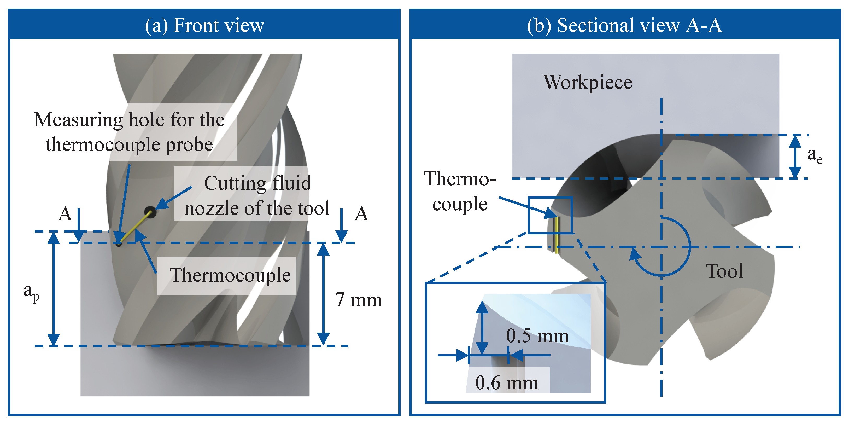
Figure 1. Illustration of the thermocouple embedded in the tool for temperature measurement.
Lubricants 13 00396 g001
Figure 2. Microstructural characterization of the Ti-6AL-4V material used in the experiment.
Lubricants 13 00396 g002
Figure 3. Experimental setup for tool life and temperature measurement during end milling with flood cooling.
Lubricants 13 00396 g003
Figure 4. Flowchart of the experimental procedure and collected process condition data.
Lubricants 13 00396 g004
Figure 5. Model setup for simulating tool temperature with defined heat input.
Lubricants 13 00396 g005
Figure 6. Model setup of CEL-based cutting simulation with cutting fluid effects.
Lubricants 13 00396 g006
Figure 7. Tool wear progression with feed travel under different cutting fluids.
Lubricants 13 00396 g007
Figure 8. Microscopic images of tool wear at the start and end of testing.
Lubricants 13 00396 g008
Figure 9. Scanning Electron Microscopy (SEM) image of wear morphology with Energy-Dispersive X-ray Spectroscopy (EDS) mapping of tungsten (W) and titanium (Ti).
Lubricants 13 00396 g009
Figure 10. Chip morphology at the initial and final stages of tool wear tests.
Lubricants 13 00396 g010
Figure 11. Development of maximum tool torque with increasing feed travel.
Lubricants 13 00396 g011
Figure 12. Polar diagram of tool torque profile at the initial and final stages of tool wear tests.
Lubricants 13 00396 g012
Figure 13. Development of measured workpiece roughness in feed direction with increasing feed travel.
Lubricants 13 00396 g013
Figure 14. Machine tool power consumption under (a) cutting oil and (b) water-based cutting fluid.
Lubricants 13 00396 g014
Figure 15. Example of tool temperature evolution under dry cutting and flood cooling with cutting oil during a total feed travel of  l f = 165 mm.
Lubricants 13 00396 g015
Figure 16. Comparison of maximum and steady-state tool temperatures measured by the thermocouple for dry cutting and different cutting fluids.
Lubricants 13 00396 g016
Figure 17. Simulated tool temperature distribution at a feed travel of  l f = 165 mm: (a) dry cutting, (b) cutting oil, and (c) emulsion/oil-free cutting fluid.
Lubricants 13 00396 g017
Figure 18. Simulation results of flow field and chip formation using (a) cutting oil and (b) emulsion/oil-free cutting fluid.
Lubricants 13 00396 g018
Table 1. Chemical composition of the workpiece material (wt%).
TiAlVFeCSnZrMo
896.34.160.2270.08060.00840.00460.0112
SiMnCrNiCuNbPdY
0.01290.00410.0420.02890.01110.04310.01080.0063
Table 2. Cutting parameters for wear and temperature analysis.
v c /m/min f z /mm/z a e /mm a p /mmProcess Type
600.0858Down Milling
Table 3. Properties of the cutting fluids used in the experiments.
EmulsionEster oil-based, highly additivated, water-emulsifiable cutting fluid
Oil-freeFull synthetic, water-soluble cutting fluid with EP additives
Cutting oilMineral oil-based, non-water-miscible cutting oil with EP additives
Table 4. Thermophysical properties of the cutting tool [17].
Temperature
T/°C
Density
ρ /kg/m3
Thermal Conductivity
κ /W/m·K
Specific Heat
c /J/kg·K
2514,800115.17198
100-106.25215
200-96.17229
300-88.44238
400-81.78243
500-75.92246
1500--250
Table 5. Parameters of the material and friction models [23].
Johnson–Cook material constitutive model of Ti-6Al-4V
A/MPaB/MPaCmn T m /°C T 0 /°C ε ˙ 0 / s 1
109810920.0141.30.931630201
Johnson–Cook damage model of Ti-6Al-4VFriction model of Ti-6Al-4V
D 1 D 2 D 3 D 4 D 5 μ 0 m f T f
−0.0720.3240.5760.01684.6440.4250.4110
Table 6. Material properties for simulating cutting oil and water-based fluids (at 40 °C).
Density
ρ /kg/m3
Thermal Conductivity
κ /W/m·K
Specific Heat
c /J/kg·K
Kinematic Viscosity
ν /mm2/s
Speed of Sound
c 0 /mm/s
Cutting oil850.50.1292006.9111.30 × 106
Water992.20.6294073.70.65791.45 × 106
Disclaimer/Publisher’s Note: The statements, opinions and data contained in all publications are solely those of the individual author(s) and contributor(s) and not of MDPI and/or the editor(s). MDPI and/or the editor(s) disclaim responsibility for any injury to people or property resulting from any ideas, methods, instructions or products referred to in the content.