Review

Theoretical Modeling and Numerical Simulation of Current-Carrying Friction and Wear: State of the Art and Challenges

1
Marine Engineering College, Dalian Maritime University, Dalian 116026, China
2
School of Mechanical Engineering, Beijing Institute of Technology, Beijing 100081, China
*
Author to whom correspondence should be addressed.
Lubricants 2025, 13(8), 370; https://doi.org/10.3390/lubricants13080370
Submission received: 15 July 2025 / Revised: 17 August 2025 / Accepted: 19 August 2025 / Published: 21 August 2025
(This article belongs to the Special Issue Advances in Dry and Lubricated Electrical Contacts)

Abstract

Current-carrying friction and wear in contact components are key issues in modern electromechanical systems such as slip rings, electrical connectors, motors, and pantographs, directly influencing their efficiency, reliability, and lifespan. Due to the limitations of experimental methods under some extreme conditions, computational simulations have become essential for studying current-carrying friction and wear in such scenarios. This paper presents a comprehensive review of theoretical modeling and numerical simulation methods for current-carrying friction and wear. It begins with discussions of approaches to solve the electrical contact resistance (ECR), a critical parameter that governs current-carrying friction and wear behaviors. Then, it delves into various modeling strategies for current-carrying friction, with an emphasis on the coupled effects of thermal, mechanical, electrical, and magnetic fields. Finally, the review addresses modeling techniques for current-carrying wear, encompassing mechanical wear and arc erosion. By summarizing existing research, this paper identifies key advancements, highlights existing challenges, and outlines future directions, advocating for the development of efficient, universal, and industry-oriented tools that can seamlessly bridge the gap between theoretical modeling and practical applications.

1. Introduction

Current-carrying friction pairs play a critical role in transmitting power or signals between moving components and are widely used in electromechanical systems, including motors [1], slip rings [2], electromagnetic launchers [3], and pantograph-catenary systems [4], as shown in Figure 1. As key components in these devices, the friction and wear failures of current-carrying friction pairs severely affect the performance and service life of the entire system. For instance, in wind turbines, wear of pitch slip rings not only reduces power generation efficiency but also causes equipment failure [5,6]. In electric ships, pod slip rings undergo severe wear and arc erosion under high-power loads, directly affecting propulsion efficiency [2,7]. During electromagnetic railgun launches, the local current density between the rail and armature can reach up to 109 A/m2, causing dramatic temperature rises and even material melting, which shortens rail lifespan [8,9]. Therefore, understanding the mechanisms of current-carrying friction and wear, particularly under extreme conditions, is crucial for evaluating their effects on system performance and for guiding the design and optimization of related equipment.
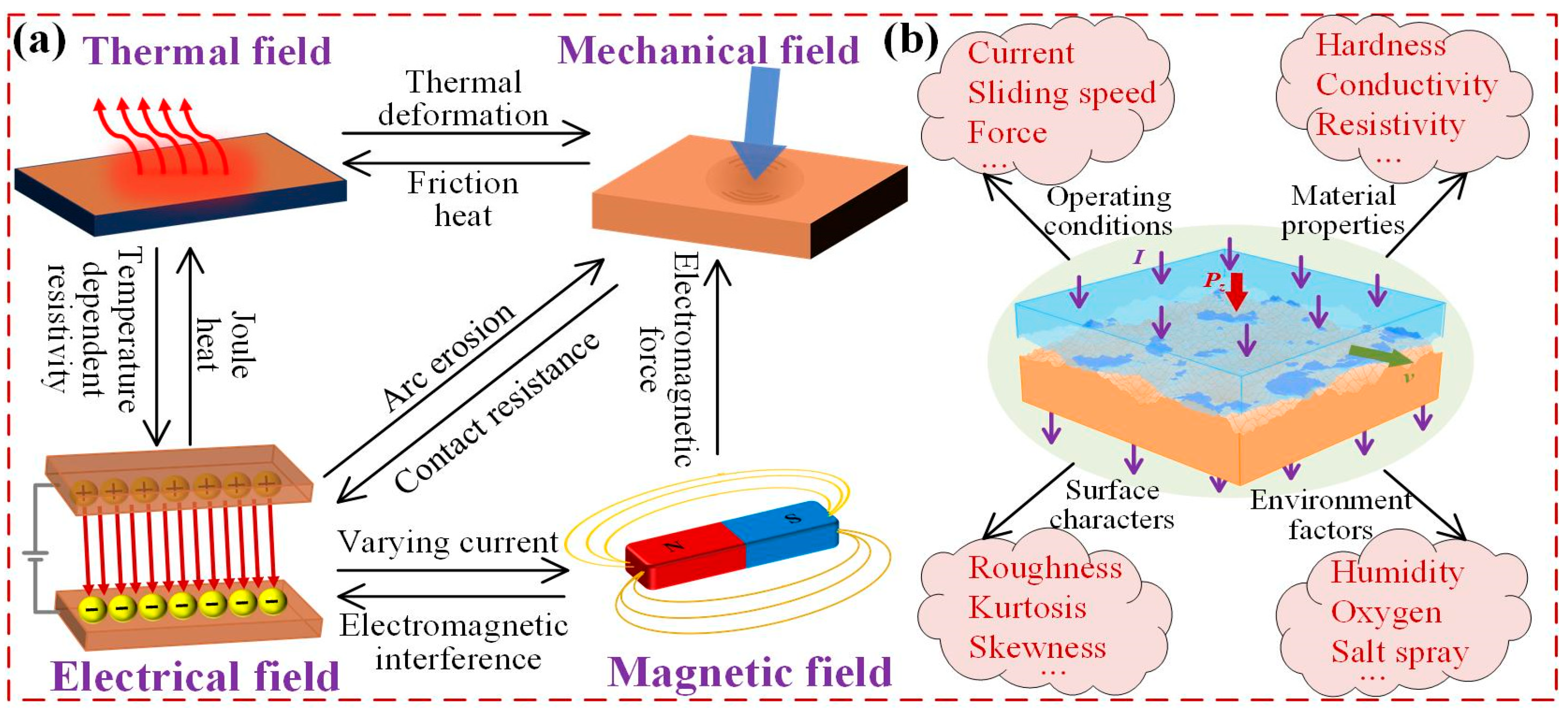
Compared to conventional friction and wear, the mechanisms of current-carrying friction and wear are more intricate, involving the coupling of thermal-mechanical-electrical-magnetic fields [10,11,12] (Figure 2a). Under mechanical load, friction heat raises the temperature, leading to thermal expansion that alters the material deformation and contact state [13]. This represents a classic thermo-mechanical coupling process, where mechanical friction is the primary driver of wear [14]. When electrical load is introduced, Joule or arc heat causes a significant temperature rise, potentially softening the material and modifying the contact interface [15,16]. On one hand, the elevated temperature alters the material’s resistivity [17] and exacerbates surface oxidation [18]; on the other hand, the altered contact state affects current constriction. Both factors significantly influence the electrical contact resistance (ECR), which in turn affects the temperature of the current-carrying friction pair. In this coupled scenario, wear is driven by both mechanical friction and electrical sparking [19,20]. Additionally, the magnetic field generated by fluctuating current can interfere with signal transmission [21] and alter the contact state through electromagnetic force [22].
In addition to the complex mechanisms, current-carrying friction and wear are influenced by various factors, including operating conditions, material properties, surface characteristics, and harsh environments (Figure 2b). Numerous studies have shown that current, force, and sliding speed are the key parameters affecting current-carrying friction and wear [23,24,25]. The wear rate increases significantly as the current increases [26], while it exhibits a characteristic “U-shaped” trend with the increase of mechanical force [14]. The effect of sliding speed is more complex, with different trends observed at different speed ranges [27,28]. Material properties and surface characteristics also play critical roles [29,30]. Friction pairs with high thermal and electrical conductivity exhibit low ECR and high heat dissipation, thereby enhancing electrical contact performance. Harder surfaces provide better wear resistance, while greater surface roughness causes an increase in localized contact pressure and current density. Environmental factors, such as humidity [31] and oxygen concentration [32], also exert a significant influence. In humid environments, a water film may form to lubricate the surface, but moisture also promotes electrochemical reactions that accelerate corrosion. Elevated oxygen levels accelerate oxidation, further degrading frictional performance.
Although numerous experimental studies have explored the effects of various factors on current-carrying friction and wear, the underlying mechanisms and the interactions among these factors remain poorly understood [10,12]. Moreover, experiments conducted under extreme operating conditions are often influenced by multiple unidentified factors, making it difficult to isolate and characterize the individual contributions of each. As such, numerical simulation becomes essential for gaining deeper insights into the mechanisms of friction and wear under diverse conditions and further optimizing the design of current-carrying friction pairs. This paper presents a comprehensive review of theoretical modeling and numerical simulation related to current-carrying friction and wear. First, methods for determining ECR, a key parameter influencing current-carrying friction and wear, are discussed. Next, modeling approaches for current-carrying frictional contact considering multi-field coupling are examined, followed by analyses of modeling current-carrying wear. Finally, the present achievements and existing challenges in this field are summarized, and future research directions are envisaged to guide further investigation and support practical applications.

2. Solving Electrical Contact Resistance (ECR)

The ECR plays a pivotal role in current-carrying friction, as it not only reflects the contact state but also directly influences current conduction and heat distribution within the friction pair. Accordingly, theoretical modeling and numerical simulation of ECR are essential for accurately characterizing current-carrying friction behavior and optimizing the design of frictional interfaces. The ECR R comprises constriction resistance Rc and film resistance Rf, which can be expressed as follows:
R = R c + R f
where Rc is caused by the constriction of current as it flows through the contact interface, and Rf results from surface oxide layers, adsorbed films, or other contaminants.

2.1. Constriction Resistance Rc

Holm derived the Rc for a single circular contact spot [33]:
R c = ( ρ 1 + ρ 2 ) / 2 a
where ρ1 and ρ2 denote the resistivity of the two contact parts, and a is the radius of the circular contact spot. Although Equation (2) has been widely used to date, its assumption that the contact spot is perfectly circular and much smaller than the contact parts may introduce significant errors. Timsit further considered the contact parts with finite size and derived detailed expressions [34,35]:
R c = ( ρ 1 + ρ 2 ) 2 a 1 1.41581 ( a b ) + 0.06322 ( a b ) 2 + 0.15261 ( a b ) 3 + 0.19998 ( a b ) 4
where a/b is the ratio of spot radius to contact part size. To simulate the contact of rough surfaces that contain multiple contact spots, Greenwood derived the Rc of multiple circular spots [36]:
R c = ρ 1 + ρ 2 4 a i + ρ 1 + ρ 2 2 π ( i j a i a j d i j ) / ( a i ) 2
where dij represents the center-to-center distance between any two circular spots. In Equation (4), both the parallel resistance of all spots and the interaction resistance between each pair of spots are considered. However, this approach still imposes limitations when modeling real, irregular contact spots.
All the aforementioned studies assume a predefined shape or distribution of contact spots without directly addressing the actual contact behavior of rough surfaces. In 2003, Barber [37] proposed that Rc is proportional to contact stiffness, establishing a quantitative link between Rc and mechanical contact. Currently, the equivalent method and the parallel method are two representative approaches for estimating the Rc of rough surface contact (Figure 3). The equivalent method, which is widely used in engineering applications, approximates multiple contact spots as a single circular contact spot with the same total area (Figure 3b), allowing the use of Equation (2) to calculate Rc. The parallel method refers to obtaining Rc by paralleling the resistance of each contact spot (Figure 3c) and has been applied to a variety of contact configurations due to its computational simplicity [38,39,40,41,42]. However, both methods introduce some errors due to neglecting the actual spot geometry or the interaction between contact spots.
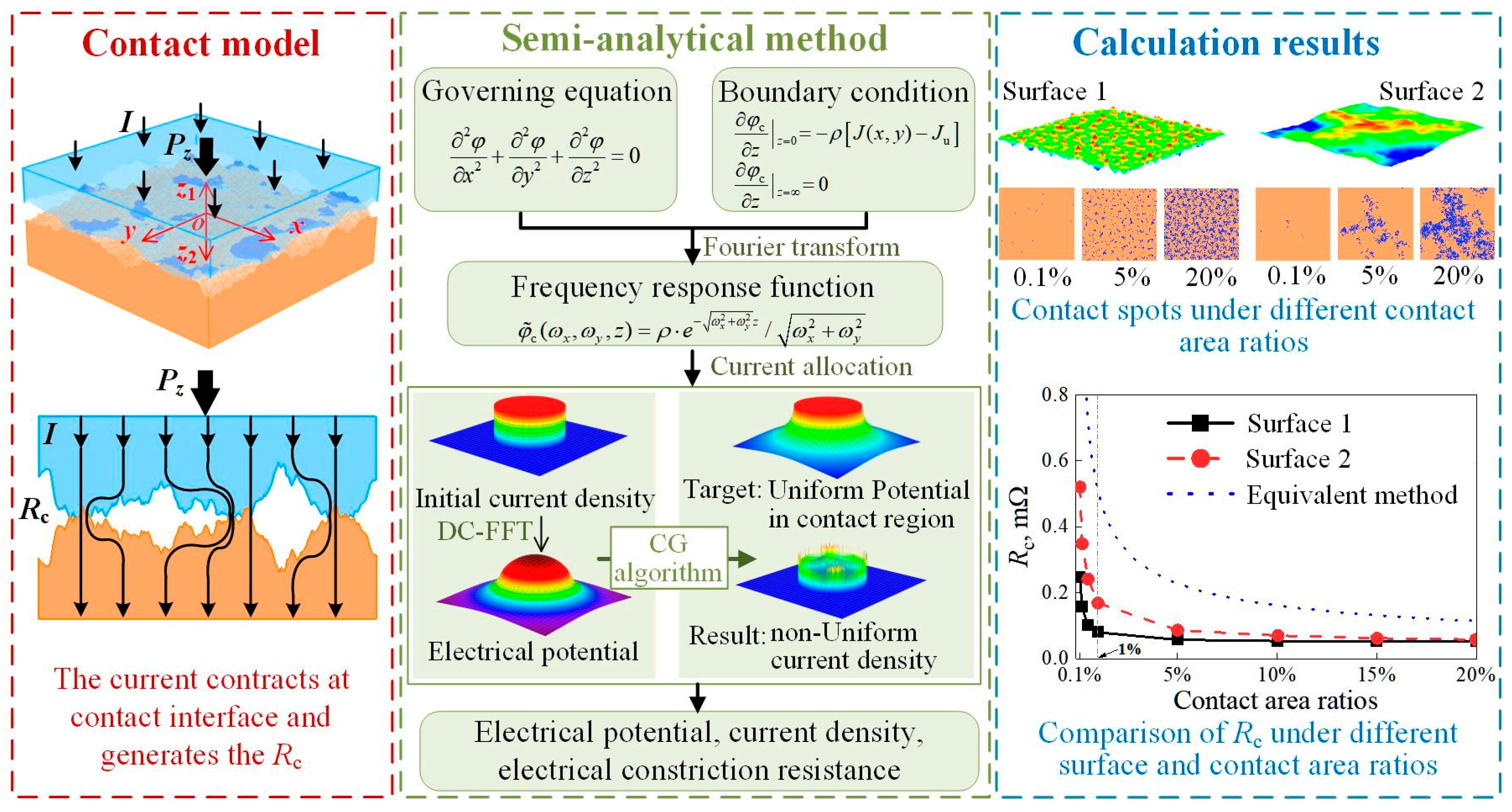
With advances in computational technology, various numerical methods have been applied to solve Rc. Nakamura et al. [43] employed the Monte Carlo method to simulate randomly distributed contact spots, followed by the finite element method (FEM) to obtain Rc. FEM naturally considers the irregular shapes of contact spots and their mutual interactions; however, achieving high accuracy requires extremely fine meshes and substantial computational resources. As a result, FEM is typically applied to relatively simple contact scenarios, such as point or line contact on smooth surfaces [44,45,46,47]. Recently, Sui et al. [48] proposed a semi-analytical model to solve Rc for the contact of rough surfaces, as shown in Figure 4. The general solution (i.e., the frequency response function) for electrical potential φc was obtained by solving a partial differential equation (PDE) in the frequency domain (i.e., the governing equation in Figure 4), where ρ is the material resistivity, and ωx and ωy are coordinate variables in the frequency domain corresponding to the x and y directions. A conjugate gradient (CG) algorithm was then proposed to determine the non-uniform current density at the contact interface, fully considering the interaction among contact spots. The discrete convolution-fast Fourier transform (DC-FFT) was employed to accelerate the calculation, which allows using very precise grids to simulate irregular shapes of contact spots and reduces computation time by at least one order of magnitude compared with FEM.

2.2. Film Resistance Rf

It is generally assumed that current flows uniformly through the oxide film; thus, the film resistance Rf of a single contact spot can be expressed as [33,49,50]:
R f = ρ f l f / A
where ρf and lf are the resistivity and thickness of the oxide film, and A is the area of the contact spot. The electron tunneling theory proposed by Simmons [51], which models electron transport through insulating films, offers another approach for calculating Rf [52,53]:
R f = Δ S exp ( 1.025 Δ S φ L 1 / 2 ) 3.16 × 10 10 φ L 1 / 2 1 A
where ∆S = S2S1, S1 = 6/(0) and S2 = lf − 6/(0) are the limits of barrier at Fermi level, K is the dielectric constant, φL = φ0 − [5.75/(KS)]·ln[S2(lfS1)/S1/(lfS2)], φ0 is the energy height above the Fermi level of conductive surface. Both these methods require prior knowledge of the film’s thickness and contact area. However, during current-carrying friction, especially under high-speed or high-current conditions, the oxide film undergoes dynamic evolution, which significantly influences both Rf and the overall tribological performance [54]. Kondo et al. [55] used FEM to simulate the decrease of Rf with increasing loading due to the fracture of the oxide film. Currently, there remains a lack of simulation methods capable of capturing the growth and evolution of oxide films during current-carrying friction, and the resulting changes in Rf require further investigation.
The phase-field method (PFM) is a numerical technique that has recently gained widespread attention for its ability to address physical problems involving complex interfaces or phase transformation processes. PFM offers several distinct advantages in predicting the evolution of oxide films: it inherently incorporates time-dependent behavior, naturally describes interface evolution without requiring explicit interface tracking, and readily accounts for multi-field coupling effects. Yang et al. [56] developed a 2D phase-field model to simulate the growth of oxide film and investigate its effects on the surface roughness. Recently, Wang et al. [57] applied PFM to investigate the oxidation of alloy surfaces under high-temperature conditions, providing a valuable foundation for modeling surface oxidation in extreme environments. The existing phase-field models are mostly limited to 2D, whereas 3D characteristics of oxide films are essential for accurately determining Rf. Therefore, it is imperative to establish a 3D phase-field model for simulating the evolution of the oxide film and further investigating the dynamic variation of Rf under different conditions.

2.3. Total ECR

Although various methods have been developed to solve Rc and Rf, most are based solely on contact or oxidation conditions of the surfaces and fail to reveal the relationship between ECR and key engineering parameters such as working conditions, material properties, and surface roughness. How to establish this relationship is currently a primary concern in practical applications. Guo et al. [58] experimentally investigated the relationship between surface characteristics and working conditions and then derived an empirical formula of ECR based on experimental data and the GW contact model. With the development of artificial intelligence, data-driven machine learning (ML) offers strong potential for analyzing experimental data and predicting ECR across a wide range of scenarios. For instance, Cai et al. [59] conducted experiments to measure ECR under varying conditions, including load, sliding speed, current, sliding distance, and surface roughness. And then, ECR under different conditions can be obtained with high accuracy by using these experimental data and ML algorithms, as shown in Figure 5.
The above review indicates that practical methods for accurately determining ECR in engineering applications remain limited. The primary challenge lies in capturing the dynamic evolution of ECR and establishing a direct link between ECR and engineering parameters. Although data-driven ML can establish this link, its outcomes depend on the quantity and quality of experimental data. In the future, integrating physical principles into artificial intelligence may be an approach to revealing the relationship between ECR and engineering parameters with both efficiency and universality.

3. Modeling Current-Carrying Friction

ECR, as well as other critical parameters in current-carrying friction, such as temperature rise, contact pressure, and stress, are influenced by multi-field coupled effects. Consequently, multi-field coupled modeling is essential not only for revealing the underlying mechanisms of current-carrying friction but also for predicting equipment performance and preventing its failure.

3.1. Thermal Field

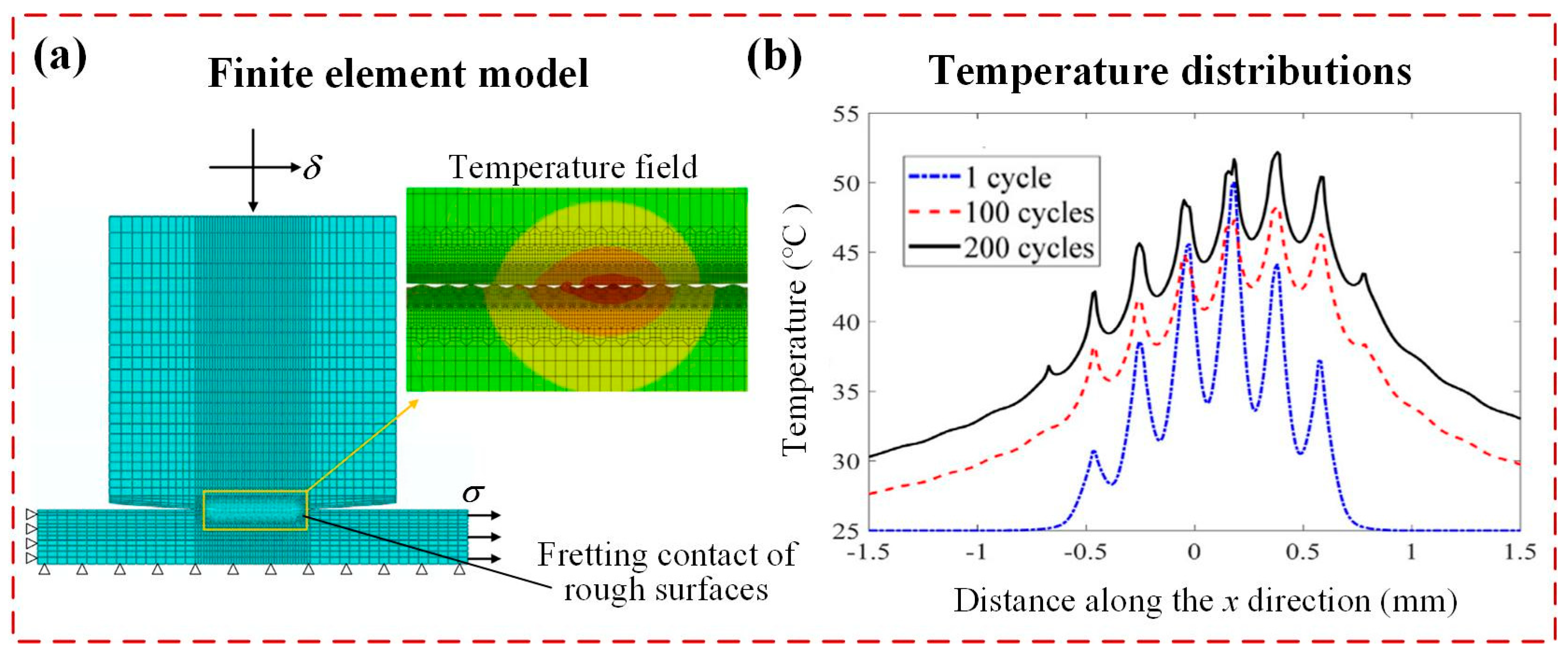
Thermal effects in current-carrying friction, mainly including friction heat and Joule heat, have attracted widespread attention due to their significant effect on the performance of friction pairs. Both the semi-analytical method (SAM) and FEM are effective approaches for simulating the temperature rise and thermal stress induced by friction. For instance, Wang et al. used SAM to model both steady-state [60] and transient [61] thermoelastic contact problems, and then obtained the distribution of frictional temperature rise and thermal displacement. Zhang et al. [13] applied SAM to solve the thermoelastic contact problem, enabling convenient analysis of temperature and stress in multi-layered materials with arbitrary designs. Shen et al. [62] employed FEM to analyze the temperature distribution and evolution during fretting friction, considering the plastic deformation, surface roughness, and wear, as shown in Figure 6.
Regarding Joule heat, Greenwood [63] theoretically derived the temperature rise of a single circular contact spot as early as 1958, establishing a foundational link between the electrical field and thermal field:
U 2 = 8 0 θ m λ ( θ ) ρ ( θ ) d θ
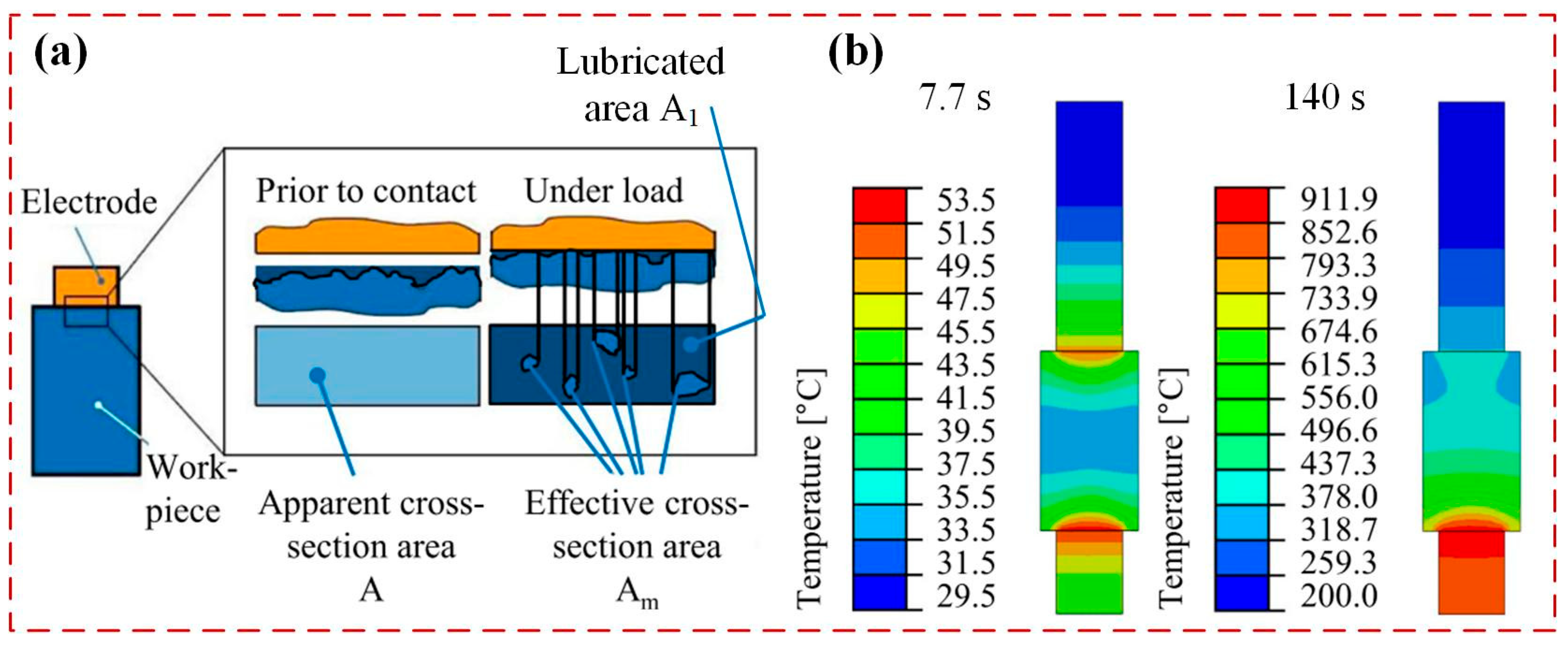
where U and θ are the contact voltage drop and temperature, λ and ρ are the thermal conductivity and electrical resistivity, and θm is the maximum temperature rise. Nituca [64] developed a static thermal analysis model to calculate Joule heat in pantographs, accounting for temperature-dependent resistivity. Plesca [65] further incorporated the combined effects of Joule heat and friction heat generated during pantograph sliding. The FEM is also a feasible method to investigate the thermal effects of Joule heat. Terhorst et al. [66] developed an FE model for electrical contact of rough surfaces and then investigated the effects of Joule heat on temperature rise in electromechanical systems (Figure 7). Guo et al. [67] applied FEM to analyze the influence of rough surface characteristics on temperature rise under different operating conditions.
In addition to friction heat and Joule heat, arc heat generated by electrical sparking also significantly affects current-carrying friction behaviors, particularly under high-power or high-speed conditions. However, existing studies on arc heat remain limited and often neglect the coupling between arc-induced thermal effects and the contact mechanics [68,69,70].

3.2. Thermal-Mechanical-Electrical Coupling

To comprehensively predict current-carrying friction performance, modeling of thermal-mechanical-electric field coupling has become a central focus in recent years. Komvopoulos [71] applied fractal theory to address sliding current-carrying contact of rough surfaces, accounting for elastoplastic contact, friction heat, and ECR but neglecting Joule heat. In addition to analytical approaches, numerical methods such as FEM and the boundary element method (BEM) have been widely used to model the current-carrying contact by solving heat-transfer, elastic mechanics, and potential equilibrium equations. Michopoulos et al. [72] proposed a multi-scale model to solve the current-carrying contact problem, where the macroscopic scale is solved by FEM, while the mesoscopic and microscopic scales are solved by the analytical method. The comparison of ECR histories between the model and experimental values was also conducted, showing that theoretical results are in good agreement with the experimental data, with only slightly higher values in the initial stage. Ke et al. analytically solved the thermo-mechanical-electrical coupled contact problem of a single asperity [50] and further analyzed rough surface contact using the parallel method, where the distribution of contact spots was solved via BEM [73,74], as shown in Figure 8. More recently, Ke et al. [75] developed a new BEM-based model that accounts for interactions between contact spots by directly solving the Laplace equation for electric potential and has higher accuracy than the parallel method.
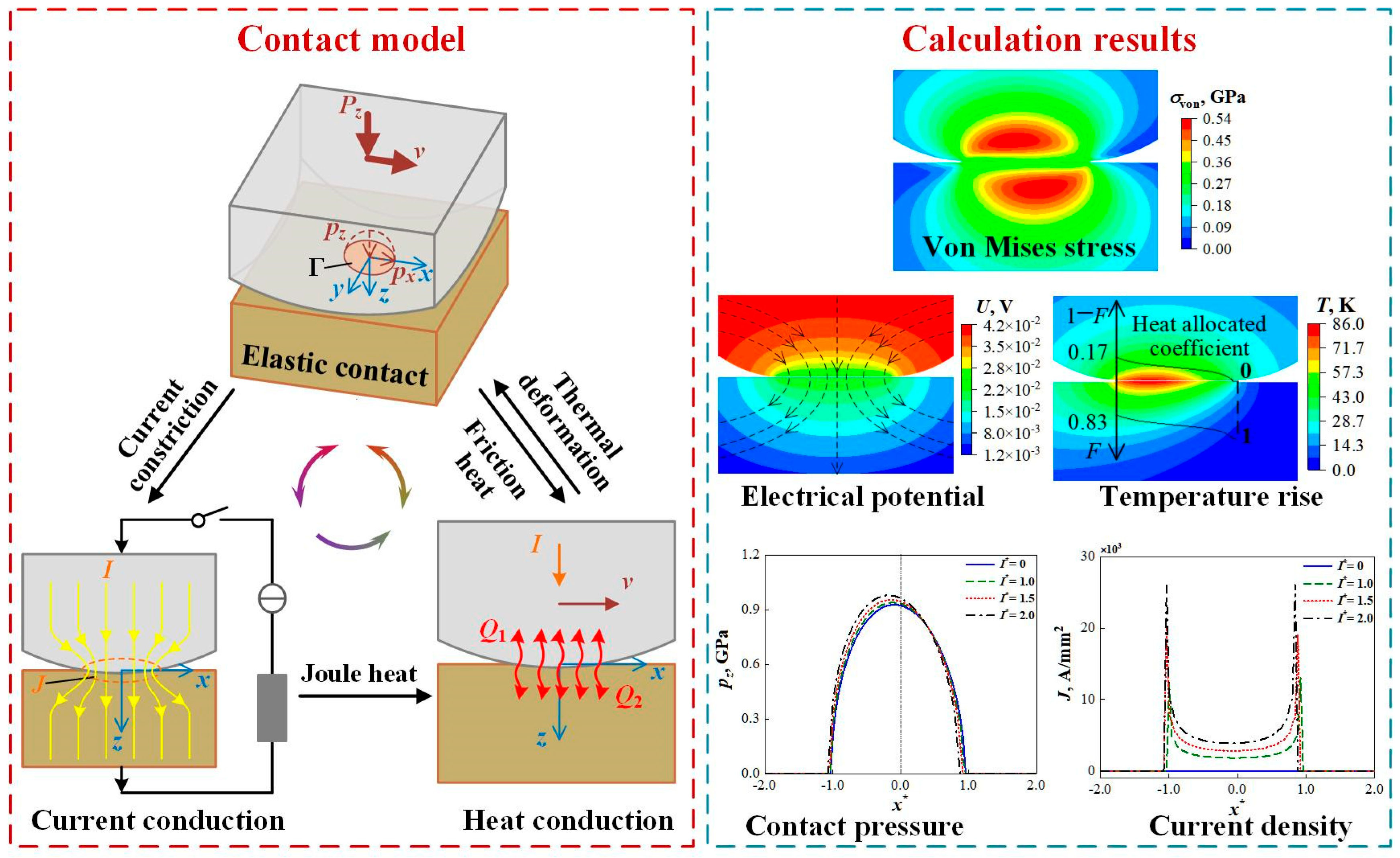
Both models proposed by Michopoulos and Ke mainly focus on static contact conditions and therefore do not involve the friction heat. More recently, Sui et al. [76] developed a semi-analytical model that fully couples the thermal-mechanical-electrical field to solve the 3D sliding current-carrying frictional contact problem, as shown in Figure 9. This model incorporates the combined effects of friction heat and Joule heat, as well as non-uniform allocation of the heat flow towards two contact surfaces—an aspect particularly important when the contact materials are dissimilar. Based on this framework, the current-carrying friction performance under various operating conditions can be efficiently predicted, as illustrated in Figure 9.
Although numerous models have been proposed to analyze current-carrying friction, several challenges remain, particularly for extreme operating conditions such as high-power and high-speed. The existing models often assume constant material properties, neglecting the temperature-dependent variations in elastic modulus and electrical resistivity at elevated temperatures. In addition, the present models are still limited to steady-state analysis, lacking the ability to capture the dynamic evolution of current-carrying friction performance.

3.3. Thermal-Mechanical-Electrical-Magnetic Coupling

In current-carrying friction, the magnetic field generated by varying current can significantly affect the performance of friction pairs. The electromagnetic force, which arises from the interaction between current and magnetic field, directly alters the contact pressure and affects the contact behavior. Additionally, electromagnetic radiation and interference caused by the magnetic field or electrical arc may disrupt signal transmission in current-carrying friction systems. At present, the effects of the magnetic field on current-carrying friction are primarily investigated through experiments. For example, He et al. [22] introduced permanent magnets to simulate a magnetic environment and examine the influence of magnetic field intensity on the friction coefficient. The results indicate that as the magnetic induction intensity increases, the friction coefficient initially decreases slightly and then increases sharply. The turning point occurs at a magnetic induction intensity of 0.1 T, beyond which the friction-increasing effect of the magnetic field (crack initiation) outweighs its friction-reducing effect (oxide film formation). Guo et al. [21] investigated the distribution characteristics and influencing factors of electromagnetic noise in pantograph-catenary systems by experiments, providing a basis for further theoretical research for electromagnetic noise suppression methods.
Zhao et al. [77] developed a theoretical model to investigate the effects of the surrounding magnetic field on the contact performance of high-speed train pantograph-catenary systems whose structure is the same as Figure 1d. The study demonstrates that the traction current in the pantograph generates a significant electromagnetic force, accounting for 30% to 50% of the contact pressure and seriously affecting the dynamic behavior of pantograph-catenary systems, including both tribology performance and power transmission capability. Liu et al. [78] theoretically investigated the velocity skin effect of the current in pantographs and found it to be strongly influenced by the magnetic field, resulting in an uneven distribution and aggregation toward the trailing edge of the skateboard. Therefore, regulating the velocity skin effect via the magnetic field can improve current-carrying performance and mitigate local temperature rise on the skateboard surface. Existing models primarily concern the effects of the magnetic field on the contact state and current distribution, while the theoretical modeling and numerical simulation studies on the coupled effects of thermal-mechanical-electrical-magnetic field remain scarce and underexplored.
The above review indicates that although FEM is a versatile approach to model current-carrying friction, it remains limited in addressing the fully coupled effects of thermal-mechanical-electrical-magnetic field in rough surface contact due to the huge computational burden. By combining SAM with DC-FFT, computational efficiency can be significantly improved, enabling comprehensive consideration of multi-field coupling effects and rough surface contact while maintaining high accuracy. However, SAM still faces limitations in addressing certain problems under extreme conditions, such as considering the temperature-dependent material properties. This problem is actually solving a set of coupled PDEs in which the material properties are functions of temperature. The physical information neural network (PINN) [79] that integrates physical laws into ML algorithms has huge potential to address PDEs and has been used in contact problems under simple cases [80,81,82,83,84]. Therefore, integrating PINN with SAM or FEM to model current-carrying friction under extreme conditions for more comprehensive analysis is a promising direction for future research.

4. Modeling Current-Carrying Wear

Contact inevitably leads to material wear, and current-carrying wear is a primary cause of failure in electrical contact systems. Studies on the wear evolution of current-carrying friction pairs are of great significance for predicting the service life of related equipment. Numerous experimental studies denote that the mechanism of current-carrying wear primarily includes mechanical wear and arc erosion [10,12]. Therefore, theoretical modeling of current-carrying wear must account for both mechanical wear and arc erosion, as well as their coupled interactions.

4.1. Mechanical Wear

The mechanical wear of materials is one of the most fundamental yet critical issues in engineering. In 1953, Archard [85] proposed an adhesive wear model, now known as the “Archard model”. In this model, the radius of a hemispherical wear particle is assumed to be the radius of the contact zone when the asperity undergoes complete plastic deformation, and the wear rate is proportional to the applied load. Therefore, the wear volume can be expressed as follows [86]:
V = K P H s
where V, s, P, and H are the wear volume, sliding distance, applied load, and hardness of worn material, respectively. K is the wear coefficient, an empirical parameter determined by experiments, interpreted by Archard as the probability of wear particle formation. Although the Archard model lacks a deep understanding of the physical laws governing material wear and requires empirical determination of wear coefficients, it has still been widely used in engineering for decades due to its simple form and reliance only on working conditions and surface hardness. In 1958, Rabinowicz [87] discovered that when the contact width exceeds a certain critical size, the accumulated frictional energy surpasses the adhesion energy of the material, leading to the generation of wear particles. This critical size can be expressed as follows:
d c = 30 E W / σ Y 2
where dc, E, W, and σY represent the critical size, elastic modulus, the work of adhesion per unit area, and yield stress, respectively. Rabinowicz’s theory laid the foundation for modeling wear from an energy-based perspective and continues to inspire the development of wear models across diverse engineering applications [88,89,90,91]. The above studies primarily focus on wear induced by mechanical forces, without accounting for the effects of current and heat.
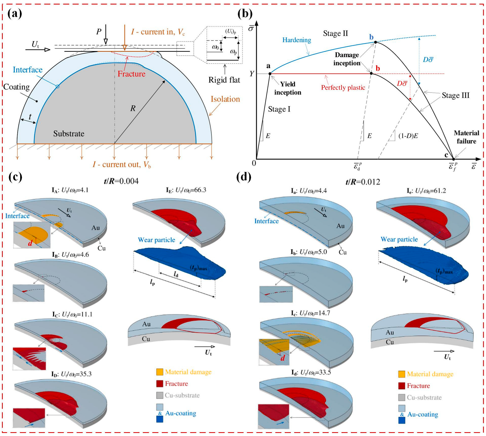
Under current-carrying conditions, the effects of electrical and thermal factors become significant, necessitating the consideration of multi-field coupling. The FEM has proven effective in addressing this complex problem [92,93,94,95,96]. Weißenfels and Wriggers [92] used FEM to develop a constitutive model for thermal-mechanical-electrical coupling based on the dissipation of friction and Joule heat at the contact interface, and simulate the temperature, electrical potential, and wear amount in current-carrying conditions. The results show that when the current is constant, total wear initially decreases and then increases with applied pressure, and the electrical effect dominates under low pressure, whereas the mechanical effect becomes predominant at higher pressure, aligning well with experimental results [14]. Recently, Zhang et al. [96] proposed a wear model of metallic coating systems under current-carrying conditions based on FEM (Figure 10a). The ductile failure is used to model the wear process, and the uniaxial stress–strain behavior of the investigated metal is illustrated in Figure 10b. Using this model, the effects of coating thickness on wear performance were analyzed, and the fracture evolutions with the increase of tangential displacement for different coating thicknesses t/R are shown in Figure 10c,d. As tangential displacement increases, flake-like wear particles gradually form, and the damage occurs on both the surface and interface for thin coating and only on the coating surface for thick coating.
Although FEM has been widely applied to model the mechanical wear under current-carrying conditions, the predicted wear morphology and volume do not yet accurately match experimental tests [93,94,95]. Furthermore, its computational inefficiency remains a major challenge, particularly in simulating long-duration or large-distance wear of rough surfaces. In 2000, Doelling et al. [97] experimentally demonstrated a strong correlation between wear volume and system entropy increase. This finding later evolved into the widely accepted energy dissipation theory, which posits that wear volume is proportional to energy dissipation, itself dependent on applied multi-physical loads [98]. Consequently, modeling wear volume as a function of multi-physical loads using energy dissipation theory is both feasible and promising. Existing models primarily focus on predicting total wear volume; however, a key future direction lies in capturing the evolution of surface morphology by linking energy dissipation to contact pressure, current density, and heat flux density.

4.2. Modeling Arc Erosion

Under high-speed or high-power conditions, frequent arc discharges occur at the contact interface, and arc erosion becomes a critical contributor to current-carrying wear [99]. In a recent study, Xu et al. [100] emphasized that neglecting arc discharge leads to an overestimation of ECR, resulting in a singular current density distribution and impairing the accurate evaluation of current-carrying performance. Existing methods for predicting current-carrying wear involving arc erosion primarily rely on experimental data to construct heuristic models [101,102]. As shown in Figure 11, Bucca et al. [101] conducted current-carrying wear tests to analyze the effects of various factors, and subsequently proposed an approximate formula to predict the wear volume NWR:
N W R = k 1 [ 1 2 ( 1 + I c I 0 ) ] α ( F m F 0 ) β F m H + k 2 R c ( F m ) I c 2 H V ( 1 u ) + k 3 u V a I c V H m ρ
where three terms represent the contributions of friction, Joule heat and arc erosion, respectively; Fm, Ic, V, Rc and Va are the contact force, current, sliding speed, ECR and electrical arc potential; H, Hm, and ρ are the material hardness, latent heat of fusion, and resistivity; other parameters are reference values or unknown coefficients that need to be determined experimentally. These models effectively incorporate the combined effects of mechanical wear and arc erosion and show good agreement with the experimental results in terms of wear volume or wear rate, but they are often complex and require numerous empirically determined coefficients, limiting their general applicability [101,102]. Moreover, although arc-induced wear is included, the models typically overlook the underlying mechanisms of arc initiation and their impact on surface morphology, which is essential for understanding the full behavior of current-carrying wear.
In 2015, Mesyats et al. [103] developed a 2D fluid dynamics model based on the heat conduction and Navier-Stokes equations, simplifying the arc erosion process as the combined effects of arc-induced heat flux and pressure on the electrode. This model effectively simulates the formation of the molten metal pool under arc erosion and the initial splashing of liquid metal. Benilov et al. [104] employed FEM to construct a 2D arc erosion model, successfully capturing the morphological evolution of arc-induced damage. Wang et al. [105] developed an axisymmetric model to simulate the initiation and evolution of arc erosion by solving hydrodynamic and heat-transfer equations in a 2D rectangular coordinate system:
𝜕 ρ 𝜕 t + ( ρ u ) = 0 𝜕 𝜕 t ( ρ u ) + ( ρ u u ) = ρ + τ + ρ g hydrodynamic equations c ρ ( 𝜕 T 𝜕 t + V T ) = ( λ T ) + j 2 σ heat-transfer equation
where ρ, t, u, τ, g, c, T, V, λ, j, and σ are the fluid density, time, fluid velocity vector, viscous stress tensor, gravitational acceleration, specific heat capacity, temperature, heat source speed, thermal conductivity, current density, and electrical conductivity, respectively. And Equation (11) satisfies the following boundary conditions:
λ | S = q q e v 𝜕 T 𝜕 r | r = 0 = 0 , T | r = r m = T 0 T | z = z m = T 0 , T | T | z = z m = T 0
where q, qev, and T0 are the energy flux density, energy flux loss, and initial temperature. Through this model, detailed insights into the geometry and temperature distribution of erosion pits were obtained.
The above review indicates that numerical methods are feasible for simulating local arc erosion characteristics. However, existing models are limited to 2D or axisymmetric form, which cannot accurately capture the 3D erosion morphology of rough surfaces. Moreover, the interaction between mechanical wear and arc erosion significantly influences current-carrying wear, yet its underlying mechanisms remain unclear. Developing comprehensive models that incorporate both mechanical wear and arc erosion, while fully accounting for their coupled effects, remains a critical scientific challenge in the study of current-carrying wear.

5. Conclusions and Perspectives

Current-carrying friction and wear play a pivotal role in the reliability and performance of modern electromechanical systems. Accurate modeling and simulation of these phenomena are essential for elucidating underlying mechanisms, predicting performance degradation, and guiding the design of advanced systems. This review systematically summarizes the theoretical modeling and numerical simulation of current-carrying friction and wear, with an emphasis on methods for solving ECR and predicting contact and wear performance under multi-field coupling effects (Table 1).
The key findings are as follows:
(1)
Theoretical formulas, FEM, and SAM are widely used in solving ECR. Among them, theoretical formulas are typically restricted to idealized scenarios, such as contact spots with regular shapes, resulting in low accuracy; FEM offers high accuracy but consumes a lot of computation time; SAM effectively balances precision and efficiency, making it better suited for more realistic rough surface contacts. Currently, research on the dynamic evolution of ECR during current-carrying friction remains limited. The primary challenge lies in capturing the evolution of the 3D geometry of the oxide film and subsequently determining the time-dependent behavior of film resistance. Modeling the evolution of 3D oxide film morphology via PFM, in combination with electron tunneling theory for film resistance prediction, presents a promising direction.
(2)
FEM, BEM, and SAM have proven effective in addressing multi-field coupling problems in current-carrying friction with high accuracy. FEM offers strong geometric adaptability and modeling flexibility but is limited due to high computational cost. BEM and SAM are more efficient; however, BEM struggles to obtain fundamental solutions under multi-field coupling, and SAM poorly accommodates the actual geometry of contact parts. Furthermore, their adaptability remains limited under complex conditions such as high-power, high-speed, and alternating current. The primary challenges lie in incorporating temperature-dependent material properties and modeling the effects of magnetic fields induced by alternating currents at the contact interface. To address these limitations, future efforts could focus on two aspects: capturing the spatial variability of material properties to account for temperature dependence; coupling magnetic field effects with thermal-mechanical-electrical fields. Additionally, to enhance the applicability of models across diverse operating environments, external factors such as humidity must also be integrated into the modeling framework.
(3)
FEM is widely employed to model current-carrying wear at the microscale, while energy dissipation principles provide an effective means to simulate macro wear amount. Effective methods for simulating long-distance surface wear evolution remain lacking. The main challenges include the absence of models capable of characterizing the 3D morphology of arc erosion and the low computational efficiency of existing approaches in capturing surface evolution. A key future research direction is developing an integrated model that couples the 3D arc erosion with mechanical wear under multi-field conditions. Such a model is essential for accurately identifying arc initiation criteria and predicting current-carrying wear by capturing the synergistic effects of mechanical and electrical degradation. Additionally, incorporating energy dissipation principles into wear models could enable efficient simulation of surface morphology evolution over extended wear durations.
(4)
The advances in artificial intelligence have made the application of ML to current-carrying friction and wear a central focus of future research. For instance, employ PINN to solve complex partial differential equations in multi-field coupling problems, establish quantitative relationships between wear characteristics and engineering parameters for friction pair design, and predict the remaining service life of components based on wear evolution. In the future, the primary challenge will be to integrate physical principles with ML techniques for multi-scale modeling, spanning contact damage analysis at the asperity level to wear evolution simulation at the rough-surface level, enabling real-time prediction of component performance and remaining service life.
In summary, developing efficient and universal industry-oriented tools that bridge the gap between theoretical modeling and real-world applications is the main exploration direction in the future. The application of computer technology to current-carrying friction and wear not only enhances the theoretical understanding of its potential mechanisms but also contributes to the design and optimization of advanced electromechanical systems, ensuring their reliability and efficiency under increasingly demanding operating conditions.

Author Contributions

Y.S.: Writing—original draft preparation, Conceptualization, Formal analysis, Methodology, Funding acquisition; P.X.: Methodology, Formal analysis; G.L.: Methodology, Formal analysis; H.Z. (Hongpeng Zhang): Methodology, Formal analysis; W.W.: Conceptualization, Formal analysis, Funding acquisition; H.Z. (Haibo Zhang): Conceptualization, Formal analysis, Funding acquisition, supervision. All authors have read and agreed to the published version of the manuscript.

Funding

This research was funded by the National Natural Science Foundation of China (Grant No. 52305180 and No. U2141243) and China Postdoctoral Science Foundation (Grant No. 2025M770289).

Conflicts of Interest

The authors declare no conflicts of interest.

References

  1. Holle, M.J.; Misak, H.E.; Malik, R.A.; Alarifi, I.M.; Asmatulu, R. Structural analysis and wear behavior of different graphite-based brushes for aircraft starter generator application. Adv. Compos. Hybrid Mater. 2021, 4, 162–172. [Google Scholar] [CrossRef]
  2. Liu, B. Simulation analysis of alocal temperature field of electric propulsion slip ring. Vibroeng. Procedia 2024, 54, 1–7. [Google Scholar] [CrossRef]
  3. Yang, Y.; Liu, P.; Li, H.; Zhang, H. The Influence of projectile shielding on the internal magnetic field during an electromagnetic launch. J. Vibroeng. 2022, 24, 966–982. [Google Scholar] [CrossRef]
  4. Song, Y.; Wang, Z.; Liu, Z.; Wang, R. A spatial coupling model to study dynamic performance of pantograph-catenary with vehicle-track excitation. Mech. Syst. Signal Process. 2021, 151, 107336. [Google Scholar] [CrossRef]
  5. Zuo, X.; Xie, W.; Zhou, Y. Influence of electric current on the wear topography of electrical contact surfaces. J. Tribol.-Trans. ASME 2022, 144, 071702. [Google Scholar] [CrossRef]
  6. Wen, D.; Zhang, M.; Zhu, R.; Zuo, X.; Zhou, Y. Improving signal transmission quality of wind turbine pitch slip ring with copper matrix composites. J. Tribol.-Trans. ASME 2024, 146, 101402. [Google Scholar] [CrossRef]
  7. Arish, N.; Kamper, M.J.; Wang, R.J. Advancements in electrical marine propulsion technologies: A comprehensive overview. SAIEE Afr. Res. J. 2025, 116, 14–29. [Google Scholar] [CrossRef]
  8. Lin, Q.; Li, B. Numerical simulation of interior ballistic process of railgun based on the multi-field coupled model. Def. Technol. 2016, 12, 101–105. [Google Scholar] [CrossRef]
  9. Zhu, C.; Li, B. Analysis of sliding electric contact characteristics in augmented railgun based on the combination of contact resistance and sliding friction coefficient. Def. Technol. 2020, 16, 747–752. [Google Scholar] [CrossRef]
  10. Li, S.; Yang, X.; Kang, Y.; Li, Z.; Li, H. Progress on current-carry friction and wear: An overview from measurements to mechanism. Coatings 2022, 12, 1345. [Google Scholar] [CrossRef]
  11. Wei, P.; Wang, X.; Jing, G.; Li, F.; Bai, P.; Tian, Y. Research progress on current-carrying friction with high stability and excellent tribological behavior. Lubricants 2024, 12, 349. [Google Scholar] [CrossRef]
  12. Huang, Q.; Song, C.; Liu, Z.; Hou, X.; Pang, X.; Sun, C.; Lu, H.; Wang, S.; Zhang, Y. Research progress on the characteristics of current-carrying tribology in electrical transmission. Space Sol. Power Wirel. Transm. 2024, 1, 37–47. [Google Scholar] [CrossRef]
  13. Zhang, H.; Wang, W.; Zhang, S.; Zhao, Z. Semi-analytical solution of three-dimensional steady state thermoelastic contact problem of multilayered material under friction heating. Int. J. Therm. Sci. 2018, 127, 384–399. [Google Scholar] [CrossRef]
  14. Yasar, I.; Canakci, A.; Arslan, F. The effect of brush spring pressure on the wear behaviour of copper–graphite brushes with electrical current. Tribol. Int. 2007, 40, 1381–1386. [Google Scholar] [CrossRef]
  15. Chen, W.W.; Wang, Q.J.; Kim, W. Transient thermomechanical analysis of sliding electrical contacts of elastoplastic bodies, thermal softening, and melting inception. J. Tribol.-Trans. ASME 2009, 131, 021406. [Google Scholar] [CrossRef]
  16. He, W.; Feng, Y.; Wu, S.; Wang, W. Effect of elastoplastic thermal softening on electrical contact resistance based on the dual-iterative coupling method. IEEE Trans. Dielectr. Electr. Insul. 2023, 30, 11–19. [Google Scholar] [CrossRef]
  17. Ohkawa, F.J. Temperature dependence of electrical resistivity of metals. J. Phys. Soc. Jpn. 1978, 44, 1105–1111. [Google Scholar] [CrossRef]
  18. He, L.; Cai, Z.; Peng, J.; Deng, W.; Li, Y.; Yang, L.; Zhu, M. Effects of oxidation layer and roughness on the fretting wear behavior of copper under electrical contact. Mater. Res. Express 2020, 6, 1265e3. [Google Scholar] [CrossRef]
  19. Chen, G.; Yang, H.; Zhang, W.; Wang, X.; Zhang, S.; Zhou, Z. Experimental study on arc ablation occurring in a contact strip rubbing against a contact wire with electrical current. Tribol. Int. 2013, 61, 88–94. [Google Scholar] [CrossRef]
  20. Mei, G. Tribological performance of rigid overhead lines against pantograph sliders under DC passage. Tribol. Int. 2020, 151, 106538. [Google Scholar] [CrossRef]
  21. Guo, F.; Wang, Z.; Zheng, Z.; Zhang, J.; Wang, H. Electromagnetic noise of pantograph arc under low current conditions. Int. J. Appl. Electromagn. Mech. 2017, 53, 397–408. [Google Scholar] [CrossRef]
  22. He, Z.; Ni, Z.; Wang, H.; Yang, Z.; Wei, W.; Wang, X.; Deng, L.; Wu, G. Effect of magnetic field on the current-carrying friction and wear performance of C/Cu contact pairs. In Proceedings of the International Conference on Electrical Materials and Power Equipment, Chongqing, China, 11–15 April 2021; pp. 1–4. [Google Scholar]
  23. Shin, W.G.; Lee, S.H. An analysis of the main factors on the wear of brushes for automotive small brush-type DC motor. J. Mech. Sci. Technol. 2010, 24, 37–41. [Google Scholar] [CrossRef]
  24. Lin, Y.; Li, J.Z.; Pan, J.; Zhang, C.; Ni, D.R.; Chen, Q.; Song, W.L.; Lu, J.Y.; Li, B.; Liu, L. Current-carrying wear behavior and the interface evolution of the Cu/Al tribological pair. Eng. Fail. Anal. 2023, 153, 107549. [Google Scholar] [CrossRef]
  25. Wang, X.; Song, K.; Duan, J.; Feng, J.; Huang, T.; Xing, J. Current-carrying tribological behavior and wear mechanism of CuW composites with different W content. Tribol. Int. 2024, 200, 110125. [Google Scholar] [CrossRef]
  26. Yi, F.; Zhang, M.; Xu, Y. Effect of the electric current on the friction and wear properties of the CNT–Ag–G composites. Carbon 2005, 43, 2685–2692. [Google Scholar] [CrossRef]
  27. Bouchoucha, A.; Chekroud, S.; Paulmier, D. Influence of the electrical sliding speed on friction and wear processes in an electrical contact copper–stainless steel. Appl. Surf. Sci. 2004, 223, 330–342. [Google Scholar] [CrossRef]
  28. Ma, W.; Lu, J. Effect of sliding speed on surface modification and tribological behavior of copper–graphite composite. Tribol. Lett. 2010, 41, 363–370. [Google Scholar] [CrossRef]
  29. Findik, F.; Uzun, H. Microstructure, hardness and electrical properties of silver-based refractory contact materials. Mater. Des. 2003, 24, 489–492. [Google Scholar] [CrossRef]
  30. Liu, X.; Cai, Z.; Liu, S.; Peng, J.; Zhu, M. Effect of roughness on electrical contact performance of electronic components. Microelectron. Reliab. 2017, 74, 100–109. [Google Scholar] [CrossRef]
  31. Hu, Z.; Chen, Z.; Xia, J. Study on surface film in the wear of electrographite brushes against copper commutators for variable current and humidity. Wear 2008, 264, 11–17. [Google Scholar] [CrossRef]
  32. Ni, Z.; He, Z.; Wang, H.; Gao, G.; Yang, Z.; Wei, W. Effect of oxygen concentration on the current-carrying friction and wear performance of C/Cu contact pairs. In Proceedings of the 16th Annual Conference of China Electrotechnical Society, Singapore, 24–26 September 2021; pp. 443–450. [Google Scholar]
  33. Holm, R. Electric Contacts: Theory and Application, 4th ed.; Springer: New York, NY, USA, 1967. [Google Scholar] [CrossRef]
  34. Timsit, R.S. The potential distribution in a constricted cylinder. J. Phys. D Appl. Phys. 1977, 10, 2011. [Google Scholar] [CrossRef]
  35. Rosenfeld, A.M.; Timsit, R.S. The potential distribution in a constricted cylinder: An exact solution. Q. Appl. Math. 1981, 39, 405–417. [Google Scholar] [CrossRef]
  36. Greenwood, J. Constriction resistance and the real area of contact. Br. J. Appl. Phys. 1966, 17, 1621–1632. [Google Scholar] [CrossRef]
  37. Barber, J.R. Bounds on the electrical resistance between contacting elastic rough bodies. Proc. R. Soc. London Ser. A Math. Phys. Eng. Sci. 2003, 459, 53–66. [Google Scholar] [CrossRef]
  38. Kogut, L.; Komvopoulos, K. Electrical contact resistance theory for conductive rough surfaces. J. Appl. Phys. 2003, 94, 3153–3162. [Google Scholar] [CrossRef]
  39. Li, B.; Hong, J.; Shao, G.; Du, F. An integrated mechanical–electrical predictive model of eectrical contact resistance between two rough surfaces. Tribol. Trans. 2015, 58, 537–548. [Google Scholar] [CrossRef]
  40. Ta, W.; Qiu, S.; Wang, Y.; Yuan, J.; Gao, Y.; Zhou, Y. Volumetric contact theory to electrical contact between random rough surfaces. Tribol. Int. 2021, 160, 107007. [Google Scholar] [CrossRef]
  41. Talukder, S.; Yeo, C.D.; Hong, Y.K.; Choi, M.; Flicek, R.C.; Bishop, J.E. Analytical modeling and simulation of electrical contact resistance for elastic rough electrode surface contact including frictional temperature rise. AIP Adv. 2022, 12, 025204. [Google Scholar] [CrossRef]
  42. Zhang, M.; Zuo, X.; Zhou, Y. Fractal contact resistance model of wind pitch slip ring considering wear and self-excited vibration. Ind. Lubr. Tribol. 2024, 76, 214–230. [Google Scholar] [CrossRef]
  43. Nakamura, M.; Minowa, I. Computer simulation for the conductance of a contact interface. IEEE Trans. Compon. Hybrids Manuf. Technol. 1986, 9, 150–155. [Google Scholar] [CrossRef]
  44. Ren, W.; Chen, Y.; Wang, Z.; Xue, S.; Zhang, X. Electrical contact resistance of coated spherical contacts. IEEE Trans. Electron Devices 2016, 63, 4373–4379. [Google Scholar] [CrossRef]
  45. Korchevnik, O.; Goltsberg, R.; Kligerman, Y.; Etsion, I. Electrical resistance model of a bilayer-coated spherical contact. IEEE Trans. Compon. Packag. Manuf. Technol. 2018, 8, 1614–1620. [Google Scholar] [CrossRef]
  46. Riba, J.R.; Mancini, A.G.; Abomailek, C.; Capelli, F. A 3D-FEM-based model to predict the electrical constriction resistance of compressed contacts. Measurement 2018, 114, 44–50. [Google Scholar] [CrossRef]
  47. Ren, W.; Zhang, C.; Sun, X. Electrical contact resistance of contact bodies with cambered surface. IEEE Access 2020, 8, 93857–93867. [Google Scholar] [CrossRef]
  48. Wang, W.; Sui, Y.; Ge, X.; Zhang, H. An efficient method for solving electrical constriction resistance of rough surfaces. Tribol. Int. 2024, 197, 109808. [Google Scholar] [CrossRef]
  49. Braunovic, M.; Konchits, V.; Myshkin, N. Electrical Contacts: Fundamentals, Applications and Technology; Taylor & Francis Group, LLC.: Boca Raton, FL, USA, 2006; pp. 1–645. [Google Scholar] [CrossRef]
  50. Li, Y.; Shen, F.; Ke, L. Multi-physics electrical contact analysis considering the electrical resistance and Joule heating. Int. J. Solids Struct. 2022, 256, 111975. [Google Scholar] [CrossRef]
  51. Simmons, J.G. Generalized formula for the electric tunnel effect between similar electrodes separated by a thin insulating film. J. Appl. Phys. 1963, 34, 1793–1803. [Google Scholar] [CrossRef]
  52. Kogut, L.; Komvopoulos, K. Electrical contact resistance theory for conductive rough surfaces separated by a thin insulating film. J. Appl. Phys. 2004, 95, 576–585. [Google Scholar] [CrossRef]
  53. Jackson, R.L.; Kogut, L. Electrical contact resistance theory for anisotropic conductive films considering electron tunneling and particle flattening. IEEE Trans. Compon. Packag. Technol. 2007, 30, 59–66. [Google Scholar] [CrossRef]
  54. Ma, T.; Yu, Z.; Song, A.; Zhao, J.; Zhang, H.; Lu, H.; Han, D.; Wang, X.; Wang, W. Intermittent failure mechanism and stabilization of microscale electrical contact. Friction 2022, 11, 538–545. [Google Scholar] [CrossRef]
  55. Kondo, T.; Nakata, H.; Sekikawa, J.; Kubota, Y.; Hayakawa, K.; Nakamura, T. An analysis of relationship between contact resistance and fracture of oxide film for connector contacts using finite element method. In Proceedings of the 2014 IEEE 60th Holm Conference on Electrical Contacts (Holm), New Orleans, LA, USA, 12–15 October 2014; pp. 1–6. [Google Scholar]
  56. Yang, F.; Fang, D.; Liu, B. A theoretical model and phase field simulation on the evolution of interface roughness in the oxidation process. Model. Simul. Mater. Sci. Eng. 2012, 20, 015001. [Google Scholar] [CrossRef]
  57. Wang, R.; Ji, Y.; Cheng, T.; Xue, F.; Chen, L.; Wen, Y. Phase-field modeling of alloy oxidation at high temperatures. Acta Mater. 2023, 248, 118776. [Google Scholar] [CrossRef]
  58. Wang, Z.; Zhou, Q.; Guo, F.; Tang, A.; Wang, X.; Chen, X. Mathematical model of contact resistance in pantograph-catenary system considering rough surface characteristics. IEEE Trans. Transp. Electrif. 2022, 8, 455–465. [Google Scholar] [CrossRef]
  59. Cai, Z.; Li, C.; You, L.; Chen, X.; He, L.; Cao, Z.; Zhang, Z. Prediction of contact resistance of electrical contact wear using different machine learning algorithms. Friction 2024, 12, 1250–1271. [Google Scholar] [CrossRef]
  60. Liu, S.; Wang, Q. A three-dimensional thermomechanical model of contact between non-conforming rough surfaces. J. Tribol.-Trans. ASME 2000, 123, 17–26. [Google Scholar] [CrossRef]
  61. Liu, S.; Rodgers, M.; Wang, Q.; Keer, L.; Cheng, H. Temperature distributions and thermoelastic displacements in moving bodies. Comput. Model. Eng. Sci. 2002, 3, 465–481. [Google Scholar] [CrossRef]
  62. Shen, F.; Zhou, K. Investigation on thermal response in fretting sliding with the consideration of plastic dissipation, surface roughness and wear. Int. J. Mech. Sci. 2018, 148, 94–102. [Google Scholar] [CrossRef]
  63. Greenwood, J.A.; Williamson, J.B.P.; Bowden, F.P. Electrical conduction in solids II. Theory of temperature-dependent conductors. Proc. R. Soc. Lond. Ser. A Math. Phys. Sci. 1958, 246, 13–31. [Google Scholar] [CrossRef]
  64. Nituca, C. Thermal analysis of electrical contacts from pantograph–catenary system for power supply of electric vehicles. Electr. Power Syst. Res. 2013, 96, 211–217. [Google Scholar] [CrossRef]
  65. Plesca, A. Thermal analysis of sliding electrical contacts with mechanical friction in steady state conditions. Int. J. Therm. Sci. 2014, 84, 125–133. [Google Scholar] [CrossRef]
  66. Terhorst, M.; Ozhoga-Maslovskaja, O.; Trauth, D.; Shirobokov, A.; Mattfeld, P.; Solf, M.; Klocke, F. Electro-thermo-mechanical contact model for bulk metal forming under application of electrical resistance heating. Int. J. Adv. Manuf. Technol. 2016, 89, 3601–3618. [Google Scholar] [CrossRef]
  67. Guo, F.; Gu, X.; Li, L.; Wang, Z.; Wang, T.; Jia, S. Effect of surface microparameters on contact temperature of sliding electrical contact. IEEE Trans. Ind. Inform. 2022, 18, 5972–5981. [Google Scholar] [CrossRef]
  68. Hu, J.; Tsai, H.L. Heat and mass transfer in gas metal arc welding. Part I: The arc. Int. J. Heat Mass Transf. 2007, 50, 833–846. [Google Scholar] [CrossRef]
  69. Kharin, S.N. Mathematical models of heat and mass transfer in electrical contacts. In Proceedings of the 2015 IEEE 61st Holm Conference on Electrical Contacts (Holm), San Diego, CA, USA, 11–14 October 2015; pp. 1–21. [Google Scholar]
  70. Zhu, G.-y.; Gao, G.-q.; Wu, G.-n.; Gu, Z.; Wu, J.; Hao, J. Modeling pantograph–catenary arcing. Proc. Inst. Mech. Eng. Part F J. Rail Rapid Transit 2016, 230, 1687–1697. [Google Scholar] [CrossRef]
  71. Komvopoulos, K. A multiscale theoretical analysis of the mechanical, thermal, and electrical characteristics of rough contact interfaces demonstrating fractal behavior. Front. Mech. Eng. 2020, 6, 36. [Google Scholar] [CrossRef]
  72. Michopoulos, J.G.; Young, M.; Iliopoulos, A. A multiphysics theory for the static contact of deformable conductors with fractal rough surfaces. IEEE Trans. Plasma Sci. 2015, 43, 1597–1610. [Google Scholar] [CrossRef]
  73. Li, Y.; Shen, F.; Güler, M.A.; Ke, L. A rough surface electrical contact model considering the interaction between asperities. Tribol. Int. 2023, 190, 109044. [Google Scholar] [CrossRef]
  74. Li, Y.; Shen, F.; Güler, M.A.; Ke, L. Modeling multi-physics electrical contact on rough surfaces considering elastic-plastic deformation. Int. J. Mech. Sci. 2024, 269, 109066. [Google Scholar] [CrossRef]
  75. Li, Y.; Shen, F.; Güler, M.A.; Ke, L. An efficient method for electro-thermo-mechanical coupling effect in electrical contact on rough surfaces. Int. J. Heat Mass Transf. 2024, 226, 125492. [Google Scholar] [CrossRef]
  76. Sui, Y.; Wang, W.; Zhang, H.; Xie, Y. Modeling 3D sliding electrical contact considering fully coupled thermal-mechanical-electrical effects. Tribol. Int. 2023, 184, 108491. [Google Scholar] [CrossRef]
  77. Zhao, Y.; Wu, G.; Gao, G.; Wang, W.; Zhou, L. Study on electromagnetic force of pantograph-catenary system. J. China Railw. Soc. 2014, 36, 28–32. [Google Scholar] [CrossRef]
  78. Liu, X.; Yang, Z.; Xiao, S.; Duan, X.; Gao, G.; Wei, W.; Wu, G.; Rotaru, M.; Sykulski, J.K. Multi-physics analysis and optimisation of high-speed train pantograph-catenary systems allowing for velocity skin effect. High Volt. 2020, 5, 654–661. [Google Scholar] [CrossRef]
  79. Raissi, M.; Perdikaris, P.; Karniadakis, G.E. Physics-informed neural networks: A deep learning framework for solving forward and inverse problems involving nonlinear partial differential equations. J. Comput. Phys. 2019, 378, 686–707. [Google Scholar] [CrossRef]
  80. Sahin, T.; von Danwitz, M.; Popp, A. Solving forward and inverse problems of contact mechanics using physics-informed neural networks. Adv. Model. Simul. Eng. Sci. 2024, 11, 11. [Google Scholar] [CrossRef]
  81. Xia, Y.; Meng, Y. Physics-informed neural network (PINN) for solving frictional contact temperature and inversely evaluating relevant input parameters. Lubricants 2024, 12, 62. [Google Scholar] [CrossRef]
  82. Oh, H.; Jo, G. Physics-informed neural network for the heat equation under imperfect contact conditions and its error analysis. AIMS Math. 2025, 10, 7920–7940. [Google Scholar] [CrossRef]
  83. Zhou, Y.; Song, H. Physics-informed neural network approach to randomly rough surface contact mechanics. Tribol. Lett. 2025, 73, 88. [Google Scholar] [CrossRef]
  84. Bai, J.; Lin, Z.; Wang, Y.; Wen, J.; Liu, Y.; Rabczuk, T.; Gu, Y.; Feng, X. Energy-based physics-informed neural network for frictionless contact problems under large deformation. Comput. Methods Appl. Mech. Eng. 2025, 437, 117787. [Google Scholar] [CrossRef]
  85. Archard, J.F. Contact and rubbing of flat surfaces. J. Appl. Phys. 1953, 24, 981–988. [Google Scholar] [CrossRef]
  86. Archard, J.F.; Hirst, W.; Allibone, T.E. The wear of metals under unlubricated conditions. Proc. R. Soc. Lond. Ser. A Math. Phys. Sci. 1956, 236, 397–410. [Google Scholar] [CrossRef]
  87. Rabinowicz, E. The effect of size on the looseness of wear fragments. Wear 1958, 2, 4–8. [Google Scholar] [CrossRef]
  88. Aghababaei, R.; Warner, D.H.; Molinari, J.-F. Critical length scale controls adhesive wear mechanisms. Nat. Commun. 2016, 7, 11816. [Google Scholar] [CrossRef]
  89. Frérot, L.; Aghababaei, R.; Molinari, J.-F. A mechanistic understanding of the wear coefficient: From single to multiple asperities contact. J. Mech. Phys. Solids 2018, 114, 172–184. [Google Scholar] [CrossRef]
  90. Brink, T.; Frérot, L.; Molinari, J.-F. A parameter-free mechanistic model of the adhesive wear process of rough surfaces in sliding contact. J. Mech. Phys. Solids 2021, 147, 104238. [Google Scholar] [CrossRef]
  91. Cao, H.; Tian, Y.; Meng, Y. A fracture-induced adhesive wear criterion and its application to the simulation of wear process of the point contacts under mixed lubrication condition. Facta Univ. Ser. Mech. Eng. 2021, 19, 23–38. [Google Scholar] [CrossRef]
  92. Weißenfels, C.; Wriggers, P. Numerical modeling of electrical contacts. Comput. Mech. 2009, 46, 301–314. [Google Scholar] [CrossRef]
  93. Jiang, X.; Pan, F.; Shao, G.; Huang, J.; Hong, J.; Zhou, A. Prediction of electrical contact endurance subject to micro-slip wear using friction energy dissipation approach. Friction 2018, 7, 537–550. [Google Scholar] [CrossRef]
  94. Shen, F.; Ke, L. Numerical study of coupled electrical-thermal-mechanical-wear behavior in electrical contacts. Metals 2021, 11, 955. [Google Scholar] [CrossRef]
  95. Yang, X.; Li, X.; Wang, S. Study on simulation of multifield coupled wear in reciprocating electrical contact. Ind. Lubr. Tribol. 2022, 75, 98–109. [Google Scholar] [CrossRef]
  96. Zhang, H.; Wu, X.; Wang, W. Modeling contact of Au-coated sphere with rigid flat: Electrical contact resistance, adhesive wear and friction. Int. J. Mech. Sci. 2023, 246, 108152. [Google Scholar] [CrossRef]
  97. Doelling, K.L.; Ling, F.F.; Bryant, M.D.; Heilman, B.P. An experimental study of the correlation between wear and entropy flow in machinery components. J. Appl. Phys. 2000, 88, 2999–3003. [Google Scholar] [CrossRef]
  98. Lijesh, K.P.; Khonsari, M.M. On the degradation of tribo-components in boundary and mixed lubrication regimes. Tribol. Lett. 2018, 67, 12. [Google Scholar] [CrossRef]
  99. Song, C.; Liu, Z.; Zhang, Y.; Sun, C.; Liu, Z.; Zhang, Y. Generation conditions of rolling current-carrying associated arc on Cu-Cu pairs and the surface damage mechanisms. Eng. Fail. Anal. 2024, 159, 108103. [Google Scholar] [CrossRef]
  100. Xu, Y.; Wu, Y.; Jackson, R.L. Electrical contact with dielectric breakdown of interfacial gap. J. Tribol.-Trans. ASME 2025, 147, 051109. [Google Scholar] [CrossRef]
  101. Bucca, G.; Collina, A. Electromechanical interaction between carbon-based pantograph strip and copper contact wire: A heuristic wear model. Tribol. Int. 2015, 92, 47–56. [Google Scholar] [CrossRef]
  102. Wei, X.K.; Meng, H.F.; He, J.H.; Jia, L.M.; Li, Z.G. Wear analysis and prediction of rigid catenary contact wire and pantograph strip for railway system. Wear 2020, 442–443, 203118. [Google Scholar] [CrossRef]
  103. Mesyats, G.A.; Uimanov, I.V. Hydrodynamics of the molten metal during the crater formation on the cathode surface in a vacuum arc. IEEE Trans. Plasma Sci. 2015, 43, 2241–2246. [Google Scholar] [CrossRef]
  104. Cunha, M.D.; Kaufmann, H.T.C.; Benilov, M.S.; Hartmann, W.; Wenzel, N. Detailed numerical simulation of cathode spots in vacuum arcs—I. IEEE Trans. Plasma Sci. 2017, 45, 2060–2069. [Google Scholar] [CrossRef]
  105. Zhang, X.; Wang, L.; Jia, S.; Shmelev, D.L. Modeling of cathode spot crater formation and development in vacuum arc. J. Phys. D Appl. Phys. 2017, 50, 455203. [Google Scholar] [CrossRef]
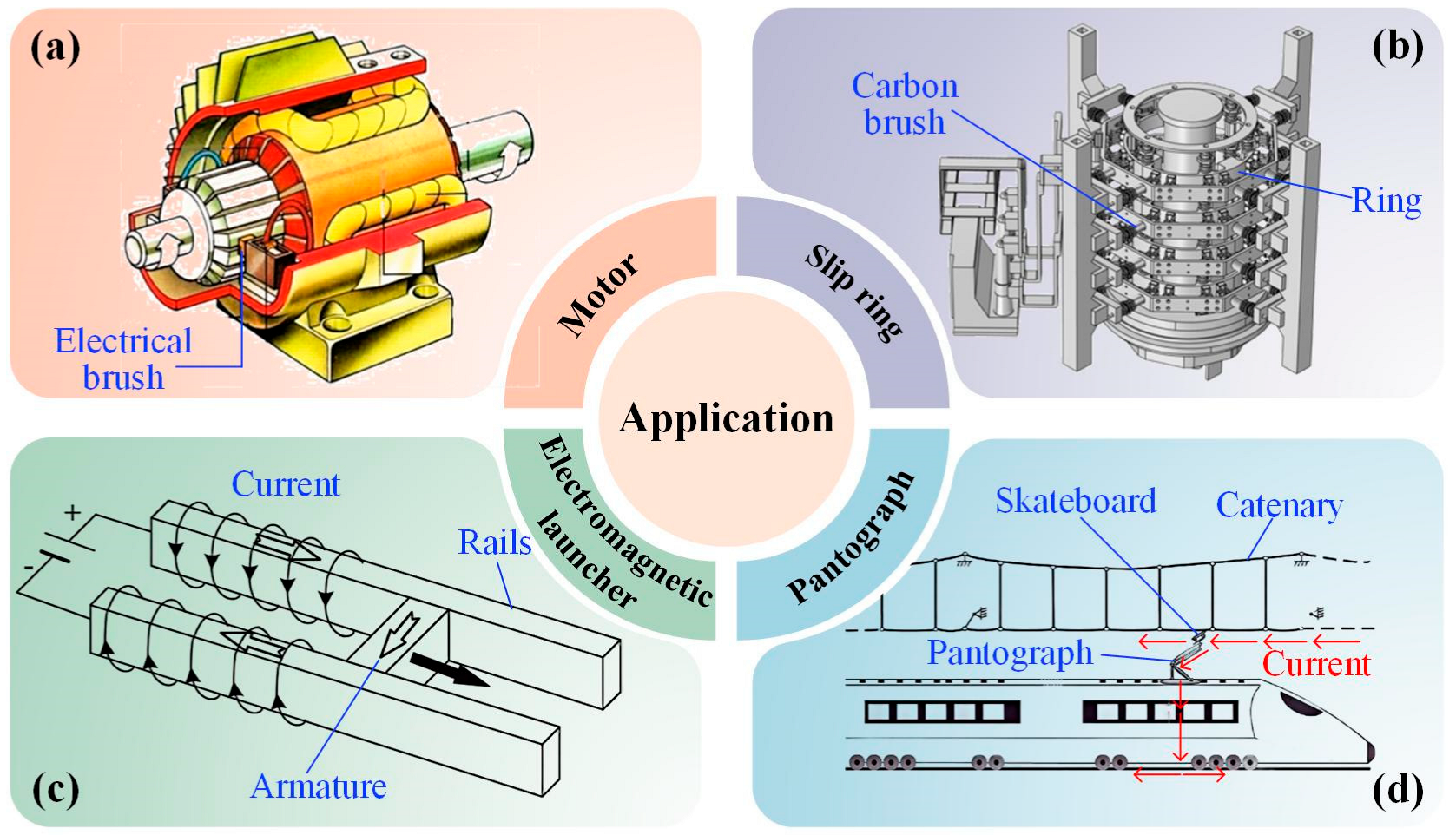
Figure 1. The applications of current-carrying friction pairs in electromechanical systems: (a) motors [1], (b) slip rings [2], (c) electromagnetic launchers [3], (d) pantographs [4]. Reproduced with permission from Refs. [1,2,3,4]; © Springer Nature, 2021; Open access; Open access; © Elsevier, 2021.
Lubricants 13 00370 g001
Figure 2. (a) Mechanisms of current-carrying friction and wear involving thermal-mechanical-electrical-magnetic coupling, (b) different factors affecting current-carrying friction and wear.
Lubricants 13 00370 g002
Figure 3. (a) Schematic of current-carrying friction and the simplified method to obtain Rc: (b) equivalent method and (c) parallel method.
Lubricants 13 00370 g003
Figure 4. The semi-analytical model and calculation results for the Rc of rough surfaces [48]. Reproduced with permission from Ref. [48]; © The authors, 2024.
Lubricants 13 00370 g004
Figure 5. Machine learning flow chart for predicting the ECR [59]. Reproduced with permission from Ref. [59]; Open access.
Lubricants 13 00370 g005
Figure 6. The (a) finite element model and (b) results for the thermoelastic fretting contact problem [62]. Reproduced with permission from Ref. [62]; © Elsevier, 2018.
Lubricants 13 00370 g006
Figure 7. The (a) model and (b) temperature distribution for electrical contact of rough surfaces [66]. Reproduced with permission from Ref. [66]; © Springer Nature, 2016.
Lubricants 13 00370 g007
Figure 8. The current-carrying contact model based on the theoretical derivation and BEM [73]. Reproduced with permission from Ref. [73]; © Elsevier, 2023.
Lubricants 13 00370 g008
Figure 9. Semi-analytical model and calculation results for sliding current-carrying frictional contact problem [76]. Reproduced with permission from Ref. [76]; © The authors, 2023.
Lubricants 13 00370 g009
Figure 10. (a) Finite element model for current-carrying wear of coating system, (b) uniaxial stress–strain behavior of investigated metal material, (c) fracture evolution for coating thickness t/R = 0.004, (d) fracture evolution for coating thickness t/R = 0.012 [96]. Reproduced with permission from Ref. [96]; © The authors, 2023.
Lubricants 13 00370 g010
Figure 11. Heuristic model for current-carrying wear based on experimental data [101]. Reproduced with permission from Ref. [101]; © Elsevier, 2015.
Lubricants 13 00370 g011
Table 1. Summary of methods for solving ECR and predicting contact and wear performance.
MethodsEfficiencyAccuracyCoupling DegreeScale (Spatial, Temporal)
ECRTheoretical formulas+++++Regular spots, static
FEM++++++Simple case, static
SAM+++++++++Rough surfaces, static
ML++++++Rough surfaces, static
FrictionFractal theory+++++Fractal surfaces, steady
FEM++++++Rough surfaces, transient
BEM++++++Rough surfaces, steady
SAM+++++++++Rough surfaces, steady
WearFEM+++Asperity level, short time
Energy dissipation theory+++++++Rough surfaces, long time
The number of the symbol “+” represents the level of how much larger or higher it is.
Disclaimer/Publisher’s Note: The statements, opinions and data contained in all publications are solely those of the individual author(s) and contributor(s) and not of MDPI and/or the editor(s). MDPI and/or the editor(s) disclaim responsibility for any injury to people or property resulting from any ideas, methods, instructions or products referred to in the content.