Review

Review on Tribological and Vibration Aspects in Mechanical Bearings of Electric Vehicles: Effect of Bearing Current, Shaft Voltage, and Electric Discharge Material Spalling Current

1
Department of Mechanical Engineering, Indian Institute of Technology Madras, Chennai 600036, Tamil Nadu, India
2
Department of Engineering Design, Indian Institute of Technology Madras, Chennai 600036, Tamil Nadu, India
3
Mechanical and Industrial Engineering, Louisiana State University, Baton Rouge, LA 70803, USA
*
Authors to whom correspondence should be addressed.
Lubricants 2025, 13(8), 349; https://doi.org/10.3390/lubricants13080349
Submission received: 16 May 2025 / Revised: 28 July 2025 / Accepted: 30 July 2025 / Published: 5 August 2025
(This article belongs to the Special Issue Tribology of Electric Vehicles)

Abstract

Electric motors play a decisive role in electric vehicles by converting electrical energy into mechanical motion across various drivetrain components. However, failures in these motors can interrupt the motor function, with approximately 40% of these failures stemming from bearing issues. Key contributors to bearing degradation include shaft voltage, bearing current, and electric discharge material spalling current, especially in motors powered by inverters or variable frequency drives. This review explores the tribological and vibrational aspects of bearing currents, analyzing their mechanisms and influence on electric motor performance. It addresses the challenges faced by electric vehicles, such as high-speed operation, elevated temperatures, electrical conductivity, and energy efficiency. This study investigates the origins of bearing currents, damage linked to shaft voltage and electric discharge material spalling current, and the effects of lubricant properties on bearing functionality. Moreover, it covers various methods for measuring shaft voltage and bearing current, as well as strategies to alleviate the adverse impacts of bearing currents. This comprehensive analysis aims to shed light on the detrimental effects of bearing currents on the performance and lifespan of electric motors in electric vehicles, emphasizing the importance of tribological considerations for reliable operation and durability. The aim of this study is to address the engineering problem of bearing failure in inverter-fed EV motors by integrating electrical, tribological, and lubrication perspectives. The novelty lies in proposing a conceptual link between lubricant breakdown and damage morphology to guide mitigation strategies. The study tasks include literature review, analysis of bearing current mechanisms and diagnostics, and identification of technological trends. The findings provide insights into lubricant properties and diagnostic approaches that can support industrial solutions.

1. Introduction

Electric vehicles (EVs) have gained significant global attention due to the escalating energy crisis and growing concerns over climate change [1]. Compared to conventional internal combustion (IC) engine vehicles, although EVs present evident limitations, such as large battery requirements, restricted driving range, and challenges associated with recharging infrastructure [2], EVs offer several advantages, including high power density, superior efficiency, rapid acceleration, and reduced carbon emissions, positioning them as a sustainable alternative to traditional vehicles [3]. Consequently, the production of EVs is expected to increase substantially in the coming decades, coinciding with the anticipated decline in manufacturing of fossil fuel-powered vehicles. Notably, EVs powered by renewable energy sources can achieve carbon dioxide emissions up to 4.5 times lower than those of combustion engine vehicles [4,5].
The current market offers five primary EV types: Battery Electric Vehicles (BEVs), Solar Electric Vehicles (SEVs), Plug-in Hybrid Electric Vehicles (PHEVs) or Hybrid Electric Vehicles (HEVs), Fuel Cell Electric Vehicles (FCEVs), and supply line-powered electric vehicles [6]. The efficiency and reliability of EVs are largely determined by the performance of their electric motors, in which bearings play a vital role. The presence of bearing currents and shaft voltages can accelerate bearing wear, induce premature failure, and alter surface properties, including residual compressive stress and hardness [7,8,9,10].
Bearing currents are generally classified as circulating or non-circulating, depending on their origin. Historically, magnetic asymmetries arising from factors such as uneven windings or rotor eccentricities were the primary causes of bearing currents [11,12]. In recent years, the widespread adoption of inverters and variable frequency drives (VFDs) has introduced additional challenges related to shaft voltage and inverter-induced currents [12,13]. These mechanisms collectively contribute to bearing degradation phenomena, including pitting, frosting, fluting, and corrosion, ultimately compromising motor lifespan and reliability [14,15,16]. As a result, mitigating bearing currents is critical for ensuring system reliability and cost-effectiveness in VFD-powered motor designs [17].
High-frequency common-mode voltages (CMVs), generated by pulse width modulation (PWM) inverters, are core to this problem. Unlike traditional sinusoidal power supplies that maintain balanced phase conditions and zero neutral voltage, PWM inverters produce imbalanced conditions due to rapid switching operations, resulting in CMVs at the motor neutral point [18,19,20]. These high-frequency voltages facilitate capacitive coupling between motor windings and frames, creating shaft voltages and circulating currents that preferentially flow through low-impedance paths, such as motor bearings [13,21,22]. When shaft voltages exceed the dielectric breakdown voltage of the lubricant film, high-frequency capacitively coupled bearing currents (commonly referred to as EDM or EDMS currents) arise, leading to severe bearing discharge damage [23,24,25]. Discharge damage includes electric erosion, typically manifested as pitting, frosting, fluting, and white corrosion cracks. Through experimental investigation, Liu et al. [26] established the influence of rotational speed and lubricant viscosity in the lubricating film formation, which in turn resulted in pitting and fluting in EV bearings. Prashant [27] highlighted the variables, including current flow, lubricant film thickness, resistance, bearing impedance, and voltage, that influence bearing performance. Chin et al. [28] studied the sensitivity of shaft voltage to inverter and motor parameters, and Jonjo [29] evaluated the effectiveness of nanoparticles (MWCNT and Al2O3) in greases in mitigating discharge-induced bearing damage. Lee et al. [9] demonstrated that electrical voltage and current increase tribological wear, with lubricant type playing a significant role in moderating this effect.
Although bearing currents in EV motors have been explored in prior studies, these efforts often focused on isolated aspects and lacked a comprehensive perspective integrating electrical, tribological, and lubricant influences. For instance, He et al. [2] provided a detailed review of bearing current-related failures in EVs but gave limited attention to lubricant degradation and its interaction with electrical discharges. Ma et al. [7] emphasized damage morphologies such as frosting, fluting, and white etching cracks (WECs) but offered minimal discussion on the electrical properties of lubricants and mitigation strategies. Busse et al. [11] examined PWM-related bearing currents but did not address tribological or lubricant aspects, while Schneider et al. [16], Tawfiq et al. [18], and Song et al. [30] concentrated primarily on electrical mechanisms and mitigation techniques for industrial motors, with limited focus on lubrication or diagnostics. Notay et al. [31] briefly acknowledged the tribological effects of electrical bearing damage without evaluating lubricant chemistry or its role under discharge conditions.
The present study provides a comprehensive review that integrates electrical, mechanical, and tribological mechanisms relevant to EV applications. It offers an in-depth analysis of bearing currents, EDMS currents, and shaft voltages, with a focus on their implications for motor performance and reliability. Specific emphasis is employed on the role of lubricant properties—such as dielectric strength and electrical conductivity—in influencing current flow and surface degradation. The review categorizes characteristic damage morphologies, including pitting, frosting, fluting, and white etching cracks (WECs), examines degradation mechanisms associated with EDMS currents, and addresses key operational challenges such as high-speed operation, elevated temperatures, and inverter-induced stresses. Furthermore, this review discusses advanced signal processing methods for non-intrusive detection and monitoring—an area that remains underrepresented in the prior literature.
The scope of this review is defined by the study of bearing current phenomena, associated damage mechanisms, lubricant interactions, and mitigation strategies in EV motor bearings. The research objective focuses specifically on EV motor bearings operating under inverter-fed conditions, with attention to electrical, tribological, and lubrication-related factors that contribute to bearing degradation. The details of the research field and research object of the present work are provided in Figure 1a,b, respectively. To achieve these objectives, this review was structured around four key tasks: (i) systematically considering literature on bearing currents, shaft voltages, damage mechanisms, lubricant behavior, and mitigation strategies relevant to electric motors, with an emphasis on EV applications; (ii) critically analyzing and synthesizing current knowledge on bearing current origins, damage morphologies, and lubricant influences; (iii) evaluating and comparing diagnostic approaches, particularly indirect methods such as vibration-based monitoring; and (iv) identifying technological trends and proposing future research directions to support the development of effective engineering solutions. By connecting electrical, tribological, and lubrication perspectives, this work aims to bridge critical knowledge gaps and contribute to the advancement of practical mitigation strategies to enhance the durability and reliability of EV motors.

2. Bearing Current, Shaft Voltage, and Electric Discharge Material Spalling Current Mechanisms

2.1. Bearing Current Causes

Bearing current refers to the flow of electrical current from the motor shaft through the bearing and to the motor frame. This arises due to electrical imbalances, either from internal motor asymmetries or from external sources such as inverters or variable frequency drives (VFDs). Bearing failure remains one of the primary causes of electric motor malfunction [32,33]. Although thermal and mechanical factors—including misalignment, inadequate lubrication, and poor maintenance—are major contributors to bearing failure [34], damage induced by electrically generated bearing currents represents an equally critical concern.
Bearing currents occur in electric motors when the induced voltage on the motor shaft exceeds the dielectric breakdown voltage of the lubricating film within the bearing, typically around 50 V or higher. As outlined earlier, the primary sources of bearing currents are common-mode voltage, electrostatic discharge, and magnetic asymmetries. These factors, in combination with the high switching frequencies of inverters or variable frequency drives (VFDs), generate shaft voltages that ultimately give rise to bearing currents in electric motors [35,36].
This high-frequency current, produced due to the use of inverters, increases the structural asymmetry within the motor. This creates an imbalance in the motor’s magnetic flux, resulting in the generation of additional magnetic fields. Consequently, a non-zero voltage is induced on the motor shaft due to this additional magnetic field [12]. The asymmetry within the motor primarily arises from two factors: first, the challenges in manufacturing electric motors with extremely high precision, due to issues like rotor eccentricities, casting defects, and irregular windings; second, the uneven voltage signal produced by the VFD or inverter [37,38,39].
Another cause of bearing currents is the triboelectrification phenomenon, which leads to electrostatic discharge in motor bearings. Triboelectrification occurs when dissimilar materials come into contact or rub against each other, particularly on the surfaces of dielectric materials. This results in the buildup of electric charges that can persist for a long time [40]. In the construction of electric vehicles (EVs), materials such as composites and polymers with dielectric properties are commonly used to reduce weight. These materials include cooling systems composed of highly thermally conductive insulating polymers, body structural components composed of carbon fiber-reinforced plastic (CFRP), and rubber sealing rings. The triboelectrification phenomenon in such components can cause significant charge separation between surfaces, leading to the accumulation of electrostatic charges [2]. This, in turn, results in shaft voltage, which eventually causes bearing currents and, ultimately, bearing failure.
The third cause of bearing currents is the recent introduction of VFDs and inverters in modern EVs. Specifically, these are Pulse-Width Modulation (PWM) inverters that incorporate fast-switching components like Metal-Oxide-Semiconductor Field-Effect Transistors (MOSFETs) and Insulated Gate Bipolar Transistors (IGBTs). PWM inverters are frequently used in motors to provide variable speed control [41]. Recently, there has been concern over this more complex type of bearing current phenomenon because of the growing interest in incorporating cutting-edge high-switching semiconductor technology into three-phase drive systems. High-frequency common-mode voltage is a result of the inverter’s rapid switching frequency/rate. The voltage between the motor’s neutral point and the stator core, or ground, is known as the CMV [20,22], and the equation for evaluating the CMV in the electric motors is given by Equation (1):
C M V = v A + v B + v C 3
where v A ,   v B , and v C represent the voltage (in volts) of individual phases: A, B, and C, respectively. When the electric motor is powered by a PWM inverter, the inverter transmits sinusoidal wave voltages with variable frequencies and amplitudes. The motor receives these signals through the winding process, controlled by a thyristor in the inverter circuit. When the thyristor of an inverter is switched on or off simultaneously, it is observed that the electric motor, driven by an electrical source, displays balanced sinusoidal waveforms. In such a case, the CMV, as defined by Equation (1), is zero at the motor winding’s neutral point. By doing this, it is ensured that the three-phase neutral and ground have the same voltage. However, if there is a delay in the thyristor’s switching, causing shaft voltage to be induced, a non-zero common mode voltage will occur.
From a control perspective, a higher switching frequency produces a CMV that more closely resembles the sinusoidal waveform, thereby increasing efficiency [42]. However, in the context of shaft voltage, a rapid switching frequency leads to a significant rate of change (dv/dt) in the CMV waveform. This causes the electric motor system to experience high-frequency harmonic distortion, which in turn causes high-frequency shaft voltage to occur with a notable amplitude [43]. This high-frequency shaft voltage can pass through multiple interfaces, including insulated ones, potentially causing detrimental effects.
The rapid change in voltage and current caused by high frequency and fast switching phenomenon in Insulated Gate Bipolar Transistors (IGBTs) can result in a number of major problems, including the following [44]:
  • Electromagnetic interference (EMI) that is both conducted and radiated;
  • Ground currents that flow to earth via stray capacitors are found inside motors;
  • Bearing currents resulting from the motor shaft voltage;
  • Overvoltage at motor terminals;
  • Shorter motor insulating life.
Since power cables and electric motors have parasitic capacitances, PWM inverters produce CMV at their output terminals, resulting in common-mode currents flowing. The motor shaft may experience voltage induction from these high-frequency currents. Significant bearing currents are generated when this voltage surpasses the lubricant film’s dielectric breakdown voltage, which could quickly damage the bearings. These currents also contribute to conducted electromagnetic interference (EMI), which causes malfunctions in nearby electronic equipment.

2.2. Bearing Currents, Common Mode Voltages, and Shaft Voltages

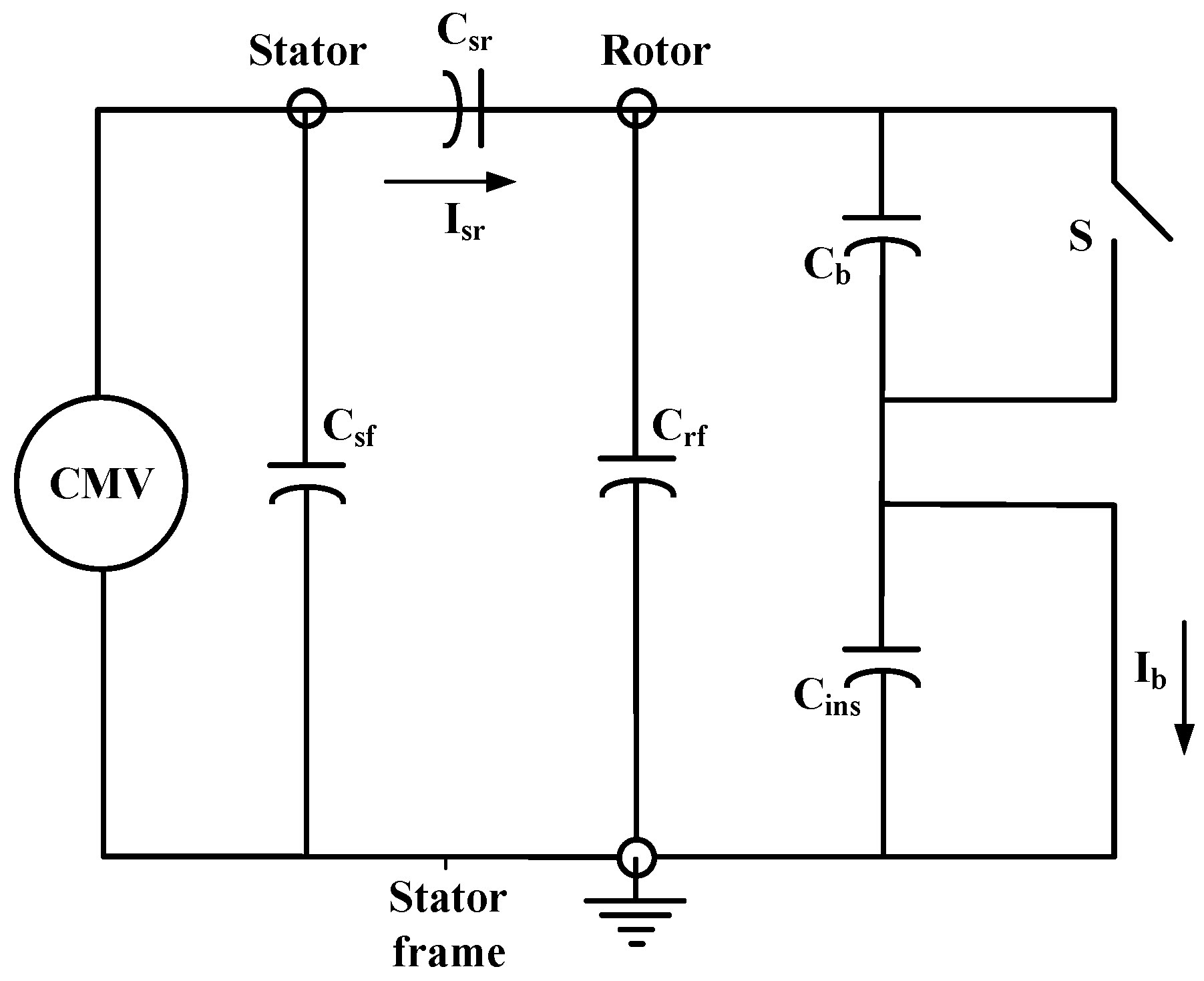
CMV is the voltage between the stator core, or ground, and the motor’s neutral point. The equivalent high-frequency CM induction motor model is shown in Figure 2. Shaft voltage (Vsh), induced across the motor shaft as a result of CMV ( V n g ), is generated by capacitive couplings between the rotor and the frame (Crf) and the stator windings (Crs). Both Vsh and V n g   represent voltages, and therefore the unit will be in volts (V), whereas Crf, C b , and Crs are capacitances, and therefore the unit will be Farads (F). The following equation, Equation (2), describes the relationship between CMV and shaft voltage [44]:
V s h =   C r s C b + C r s + C r f V n g
The bearing voltage ratio (BVR) is defined as the ratio of bearing voltage (Vb) to CMV (Vcm) at motor terminals and is described as in Equation (3):
B V R = V b V c m =   C s r C s r + C r f + 2 C b
The bearing current acts as one of the primary causes of premature motor bearing failure, which is generated due to motor shaft voltage. Therefore, to mitigate these currents, it is crucial to manage both the magnitude of the CMV and d v m / d t (i.e., the rate of change of CMV).
When a switch (S) is closed, the bearing current (in amperes) while experiencing electric discharge is determined using Equation (4):
I b   w i t h   E D M =   I m C s r C s r + C s f
While, when the switch (S) is open, the bearing current without electric discharge ( I b   w i t h o u t   E D M ) is computed using Equation (5):
I b   w i t h o u t   E D M =   I s r C b C b + C r f
where C b represents the bearing capacitance (in Farads), C i n s represents the capacitance of insulation (in Farads), I m represents the total current flowing through the CMV-induced equivalent circuit (in amperes), and I s r represents the current flowing through C s r   branch of the equivalent circuit (in amperes) [44].
Investigations are conducted into how PWM inverters’ common mode voltage affects the bearing currents, and a simple measurement system is suggested in [45]. This arrangement makes it easier to measure the bearing current and motor shaft voltage of an induction motor powered by a two-level inverter. Additionally, multilevel inverters present effective solutions to mitigate common-mode voltage and its associated problems [46,47,48]. The mitigation of shaft voltage and bearing currents through the use of multilevel inverters is presented in [49].

2.3. Flow of Circulating Current

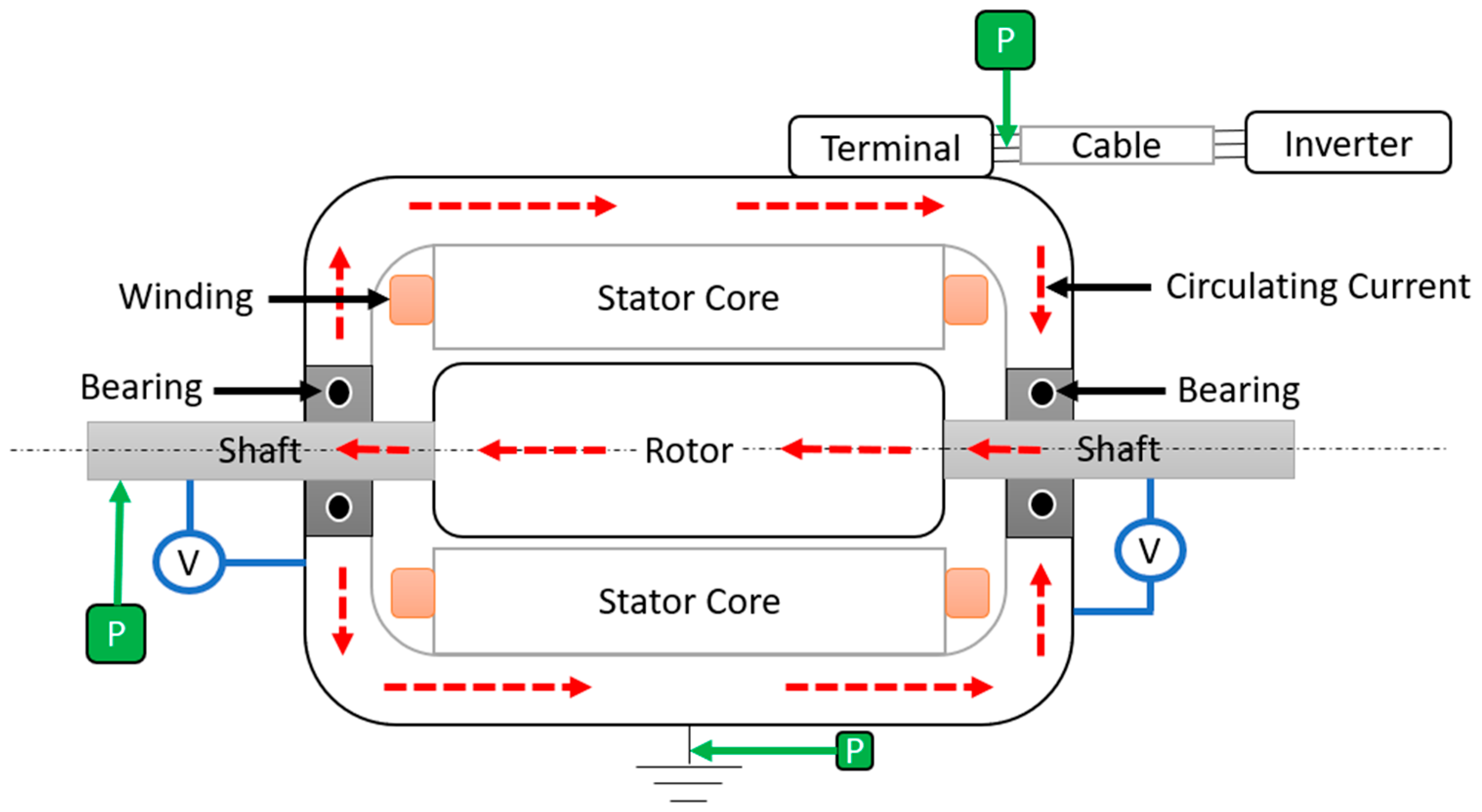
When a non-zero CMV is present, the internal coupling capacitor within the electric motor offers a low impedance ground path for the induced common mode currents [50]. This leakage current creates a surrounding magnetic field inside the motor as it travels from the motor windings to ground via capacitance. This magnetic field then induces both shaft voltage and circulating currents within the motor [51]. Leakage current enters the rotor through capacitive coupling between the winding and the rotor if the resistance of the winding to the ground via the rotor is minimal, and eventually it will find its way to the ground through the motor bearings. The induced shaft voltage will cause circulating currents to flow in one of two ways:
  • The first path involves the current flowing directly from the motor shaft, passing through bearings, then travelling through the motor or load frame, and eventually grounding itself, as shown in Figure 3a;
  • An alternative path for current flow involves the current travelling from one side of the shaft to the other, passing through one bearing, then the motor frame, and back through the opposing bearing, as shown in Figure 3b.
Generally, the bearing current tends to follow a path that reaches the ground via the load end when the electric motor’s frame lacks sufficient grounding or when insulated bearings are used. Muetze and Binder [52] investigated the “zigzag” pattern observed in the stator laminations, which results from the skin effect of high-frequency current.

2.4. Electric Discharge Material Spalling Current and Its Breakdowns

Electrical Discharge Machining (EDMS) currents in electric vehicle motor bearings arise primarily due to the presence of shaft voltages exceeding the dielectric breakdown voltage of the lubricant film separating the rolling elements from the bearing race. In inverter-driven motors, common mode voltages (CMVs) are induced on the shaft through capacitive coupling between the stator windings and the rotor, resulting in an accumulation of electrical charge on the shaft surface. When this shaft voltage surpasses the threshold that the bearing lubricant film can withstand, typically influenced by operational speed, bearing load, and lubrication condition, electrical discharges occur between the rolling elements and raceway, leading to EDMS currents. These high-frequency, low-energy pulses cause localized electrical erosion or pitting on the bearing surfaces, accelerating bearing degradation and adversely affecting the motor’s reliability and lifespan [18,53,54,55].
The mechanism of EDMS current generation is further influenced by the inverter switching characteristics, such as the switching frequency and voltage amplitude, which modulate the common mode voltage waveform. Silicon carbide (SiC) inverter technology, prominent in modern EV propulsion systems due to its high switching capability, increases the severity of both shaft voltage and EDMS currents by elevating the rate of voltage rise at the motor terminals. Studies have shown that pulses generated during inverter switching events induce capacitive currents through parasitic capacitances inherent in the motor structure, initiating the discharge cycle that characterizes EDMS currents. Consequently, these characteristics prompt the need for advanced control and mitigation strategies to minimize EDMS current effects and protect bearing health [56,57].
To address EDMS current generation, several mitigation techniques have been explored. Application of common mode filters and the implementation of active zero-sequence PWM strategies effectively reduce common mode voltage magnitude, thus diminishing the shaft voltage and suppressing EDMS currents. Moreover, electrostatic shielding and shaft grounding brushes present practical solutions for managing charge accumulation and discharge pathways, significantly reducing EDMS current occurrence and associated bearing damage. Proper implementation of these strategies is vital to enhancing the durability and operational safety of EV motor bearings, ensuring the longevity of electric drives in automotive applications [5].
The magnitude of the EDMS current can fluctuate depending on various factors, including the electric motor’s operating conditions, the presence of electrical discharge issues, and the specific motor design. The insulating properties of the lubricating film between the bearing’s electrical components and the conducting parts can also influence the magnitude of the EDMS current. The oscillograph measurements enable the observation of these voltages and their corresponding currents [58]. The performance and longevity of the electric motor are significantly impacted by electrical discharge damage inside the bearings caused by the harmful EDMS currents.
The electric arc produced due to the EDMS current inside the motor bearings causes the lubricants to deteriorate (shown in Figure 4). Figure 4a presents pristine and degraded lubricating gear oil [16]. Figure 4b presents degraded grease of NLGI grade 3, after conducting experiments for 122 h at a shaft speed of 1800 rpm, with a mechanical load of 1471 N and a DC electrical load of 3 A [59]. This happens when the voltage across the bearing is higher than the lubricating coating’s threshold voltage between the rolling elements and the bearing’s raceways. The lubricant’s breakdown field strength and the lubricating film’s thickness determine the lubricating film’s insulating capacity [60]. This indicates that the choice of lubricant can significantly affect the generation of EDMS currents in the bearings. By using conductive lubricants, it has been observed that the occurrence of EDMS currents or breakdowns can be avoided, as these lubricants inhibit the accumulation of voltage across the lubricating oil layer. Furthermore, using lubricants with higher electrical conductivity is expected to promote a predominance of resistive current during rolling bearing operation, which helps prevent the buildup of voltage across the lubricating film [61,62].

2.5. Non-Circulating and Circulating Bearing Currents

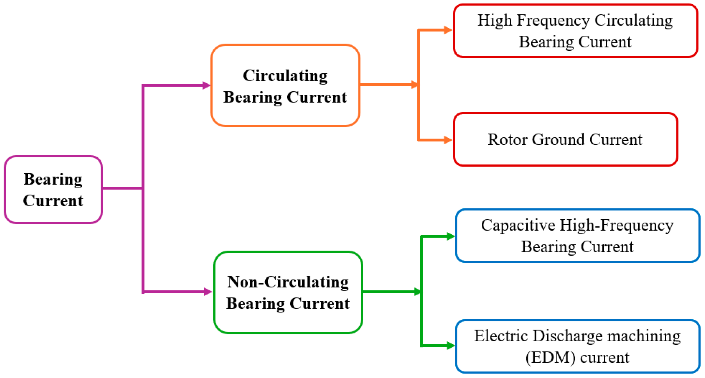
High frequency bearing currents are generally produced due to inductive and capacitive coupling within electric machinery. Parasitic capacitances and inductances are present in nearly all electric drive systems, whether they are driven by sine-wave operations or by inverters. In sine wave operations, these parasitic effects are often neglected. However, when motors are powered by inverters, the situation differs. The motor’s parasitic capacitances and inductances are excited by the high-frequency components of the CMV, which ultimately leads to the generation of bearing currents within the electric motors [63]. Classification of bearing currents based on their generation is provided in Figure 5 [64].
Non-circulating bearing currents travel from the motor’s rotor to its stator via the bearings in one direction [64]. These currents are further classified into capacitive high-frequency bearing currents and EDMS currents.
Capacitive high-frequency bearing currents are low-range currents, typically between 5–200 mA, and generally occur at low motor speeds (less than 100 rpm). At these low speeds and bearing temperatures (typically between 70–90 °C) [63]. Metallic contact may bridge the lubricant coating of the bearings, causing the bearings to lose their insulating properties and behave like ohmic resistors. This results in the production of small capacitive bearing currents. Due to their low magnitude, these currents are generally not harmful to motor components and can be neglected [18]. Additionally, the value of capacitive bearing currents depends on the bearing’s temperature, since the temperature of the bearing lubricant affects its properties, such as viscosity and thickness [65].
As mentioned earlier (Section 2.4), whenever the voltage across the bearings surpasses the threshold voltage of the lubricant’s insulating layer, it produces a destructive current known as EDMS current within the bearing, leading to arcing. The bearing voltage (Vb) under normal shaft speed and with good lubricating films can be calculated using the bearing voltage ratio (Rb) and the common mode voltage (Vm) as follows.
Vb = Rb × Vm
The bearing voltage ratio typically ranges from 3% to 10%. For instance, with a 300 V AC supply in electric vehicle drive-trains, the peak bearing voltage across the bearing will be approximately 30 V. Since the lubricating film thickness in motor bearings ranges from 0.1 to 1.4 µm, it can handle bearing voltages from 1.5 to 21 V, corresponding to a dielectric strength of 15 V/µm. If the bearing voltage exceeds 21 V, depending on the AC supply voltage, an EDMS current may occur [2]. For a 1.5 kW power-rated induction motor, the EDMS current can have a range from 0.2 to 1.4 A [17]. The value of EDMS currents depends on various factors, including lubricating film thickness, lubricant viscosity, speed, load, lubricant distribution (uniform or non-uniform), bearing interface surface roughness, and operational vibrations. Thus, despite a higher CMV value, EDMS current generation is influenced by numerous factors, making the likelihood of EDMS occurrence somewhat random.
The production of circulating bearing currents involves the use of capacitive coupling, inductive coupling, and magnetic induction, making it more complicated than the generation of non-circulating bearing currents [64]. The circulating bearing currents are further classified into two categories: high-frequency circulating bearing currents and rotor ground currents.
High-frequency circulating bearing currents arise from additional high-frequency ground currents (such as common mode currents) at the terminals of a motor, which result from capacitances between the stator winding and frame, raising the dv/dt value [63]. The primary cause of these high-frequency circulating bearing currents is magnetic flux asymmetry and frequency variations based on shaft speed. This frequency typically ranges from 100 kHz to several MHz [18]. Bearing currents are produced when the lubricating oil film breaks down due to bearing voltage, leading to currents circulating within a conductive loop. This current travels from the stator frame to the drive end bearing at one end, then flows via the motor shaft to the non-drive end bearing at the other end, and then returns to the stator frame [2]. This circulating bearing current magnitude is dependent on the size of the motor; for example, for motors with a maximum power rating of 500 kW, the highest amplitude of this current ranges from 0.5 to 20 A. Additionally, circulating bearing currents flow in opposite directions in both end bearings of an electric motor [18,66].
Rotor ground current is another type of circulating bearing current, which usually occurs when the impedance between the rotor and the ground is lower than that between the stator and the ground. This occurs because circulating currents tend to follow the path of least impedance [67]. Some portions of the rotor ground current can flow from the total ground current when the electric motor is grounded through the driving load. This type of current typically has a maximum magnitude ranging from 1 to 35 A. Due to its higher magnitude and the fact that almost all the rotor ground current goes via the motor bearings, this current is considered dangerous. It may result in premature bearing damage and, eventually, cause motor failure [18,63].

3. Morphological Damages to Bearings Due to Bearing Currents

3.1. Electrically Induced Surface Pitting

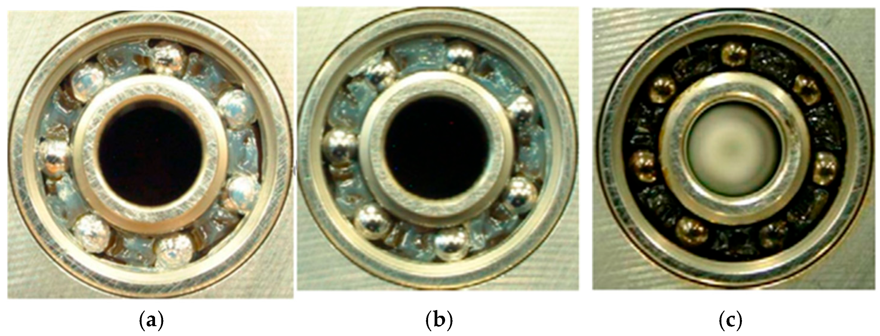
The CMV generally creates an electric field between the raceway and the roller/ball in the case of full film lubrication, and when this shaft voltage exceeds the threshold voltage value of the lubricating film, it causes an intense electric discharge between the raceway and the roller/ball [68]. This creates an electrical arc between the raceway and the roller of the bearings, which produces high temperatures on the bearing surfaces. Usually, the temperature that is generated is greater than the bearing material’s melting point, which melts the surface materials of the roller and raceway of the bearing and causes craters to form [69], which creates pitting defects on the raceways and the rollers/balls. Figure 6a,b shows the pits formed on the inner race and balls surface after performing experiments for 122 h at a shaft speed of 1800 rpm, with a mechanical load of 1471 N and a DC electrical load of 3 A. Figure 6c shows a magnified image of micro-pits near the damaged area. The details of the experiments can be found elsewhere [59]. Due to the intense single discharge pulse and much higher magnitude of current, which exists for a longer time, the size of craters in pitting defects is much larger and are randomly arranged (not in a specific pattern) [2].
Bearing current is considered to be the primary reason for the electrical pitting instead of shaft voltage, and its value required to produce the pitting defect is roughly around 90 milliamperes [68,70]. There is an increase in the wear within the bearing because of the produced pit (large-sized craters) that increases the roughness on the surfaces of the raceways and the roller/ball [71]. An important consideration in assessing the life and operating condition of a bearing is the energy generated by its currents, which can be used to estimate the pit size [7]. The amount of time needed for electrical sparks (arcing) to cause pitting to form on raceway surfaces has been studied by Prashad [27,72] by investigating the accumulation of energy and the dissipation of the lubricants with high resistivity levels. Additionally, the energy required for a material to evaporate is calculated in [73].
It is observed that with an increase in bearing currents, there is an increase in the interface power for the uniform thickness of the lubricating film. This interface power (P) is related to the pitting area (Ap) by the relation provided in Equation (7) [68]:
A p = 0.0059 P 3 0.068 P 2 + 0.46 P
where the pitting area (Ap) is in 103 μm2 and the interface power (P) is in Watts (W). Additionally, the pitting area (Ap) can be related to lubricating film thickness (h), current (I), and voltage (V) by Equation (8) [68]:
A p = 0.081 h 0.116 × V 0.289 × I 1.179
Using Equations (7) and (8), the size of the pitting area can be estimated. Additionally, this equation demonstrates the direct relationship between the bearing currents and the pit’s size.

3.2. Micro-Scale Arc-Induced Surface Texturing (Frosting)

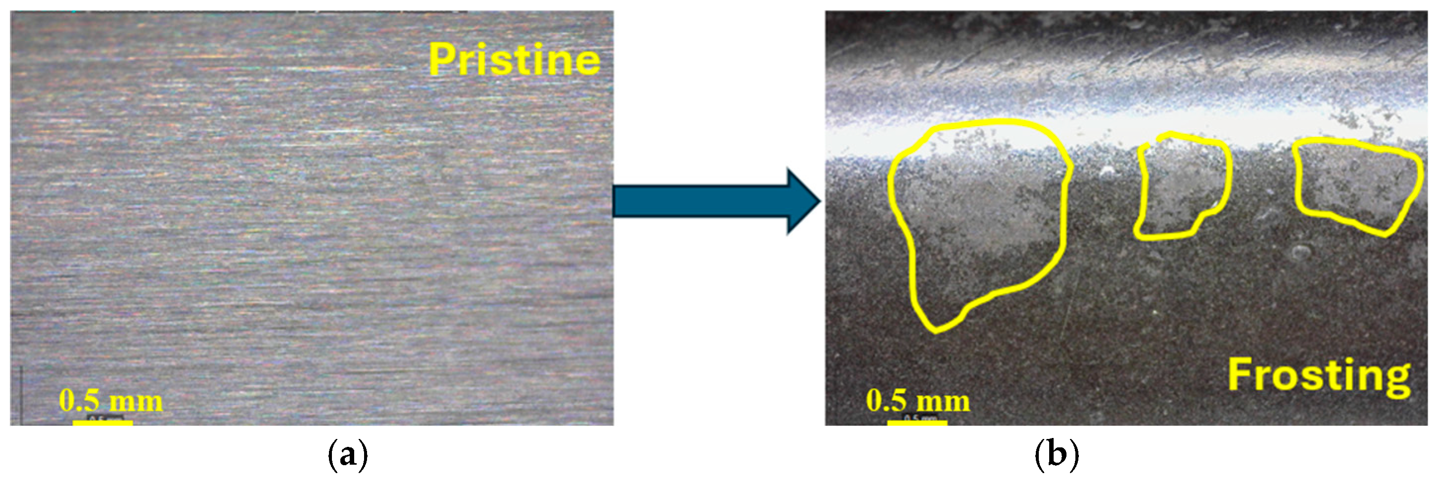
Frosting occurs when the electric discharge is weak but dense [2]. The crater size in this type of surface damage is much smaller than in pitting. It is difficult to see this defect through the naked eye because of its small crater size and satin-like look. The pristine surface and surface with frosting, after conducting experiments for 122 h with a mechanical load of 1471 N, shaft speed of 1800 rpm, and a DC electrical load of 3 A, are shown in Figure 7a and Figure 7b, respectively. When seen using a microscope, the damaged surface due to frosting looks like small and separate craters [74]. These small craters show the occurrences of the melting process because of the breakdown caused by EDMS currents (or electrolysis). It is observed that the frosted area has low hardness (because of the bearing current that results in the melting of surface material) and multiple damaged traces due to bearing currents when investigated through a scanning electron microscope (SEM) [75,76].
The production of the frosting defect on the bearing surfaces may be affected due to the loading on the bearings, since it is observed that under higher loading conditions, there is a light grey colored frosting on the raceway of the bearing along with the traces of intense melting of material because of the flow of bearing currents, while there is an occurrence of corrugated damage on the raceway of the bearing under light loading [73,77]. This may be because of the fact that there could be a thicker lubricating oil film under light radial loadings, which allows it to sustain a high value of shaft voltage across the bearing and eventually produces a higher magnitude of bearing currents, which causes much more damage to the bearings. Along with that, this results in large vibrations on the rollers/balls, which creates metal-to-metal contact between the rollers/balls and the raceway at a particular frequency, eventually leading to the formation of corrugated damage [7].

3.3. Fluting and Spark Tracks

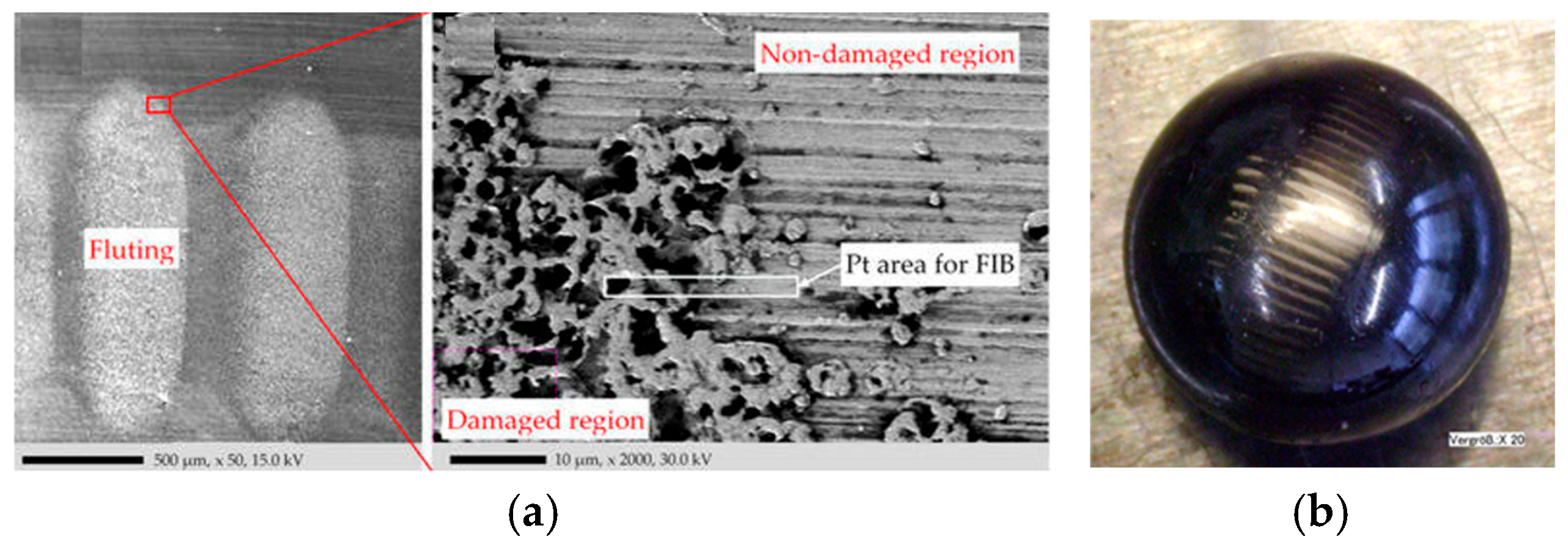
Fluting damage occurs as a result of partial melting of the surfaces of the bearing, generating a unique pattern on the bearing raceways and balls, as shown in Figure 8a,b. This partial melting occurs when the bearing currents flow through the bearing raceway and roller/ball, generating an electric spark (i.e., arcing). The unique pattern in fluting is caused by the vibration (caused by bearing currents) and the dynamic phenomenon of rolling elements, which means that because of the melting, the micro-craters (with a diameter falling within the 1 to 4 micron range) are generated, and when the ball rolls over these micro-craters in the running condition, the unique pattern is created on the raceway of the bearing. A lot of fluting damage can be hazardous and necessitate the replacement of bearings since it can result in early bearing failure, which can ultimately cause an electric motor to fail [78].
Compared to frosting, it is easy to recognize, and it travels transversely to the bearing’s raceway. Fluting is mainly caused either by the continuous flow of electrical currents or by EDMS currents. Additionally, the pattern generated by fluting is only on the quarter (or less than a quarter) of the bearing’s outer raceway [80]. It is observed that when there is a low contact resistance, it leads to electrochemical decomposition or corrosion of lubricating grease and gradually causes fluting damage, while pitting occurs due to high contact resistance.
The starting appearance of the spark tracks looks like scratches that come from foreign particles in the lubricating oil/grease. However, it is revealed when closely investigated that these are irregular and are skewed in the direction of rotation [74]. Even though it seems to be a mechanical scratch, this kind of damage has an electrical nature as well. It can be observed that there are sharp corners on the scratch, and sometimes the tracks have melted in the lower portion. Meanwhile, the round corners result from dirt particles or a tool. The spark track’s depth seems to be uniform over the complete surface. The primary reason for the spark tracks is found to be the debris that is generated from the bearing surface because of electrical discharge [2].

3.4. Subsurface White Etching Crack Formation

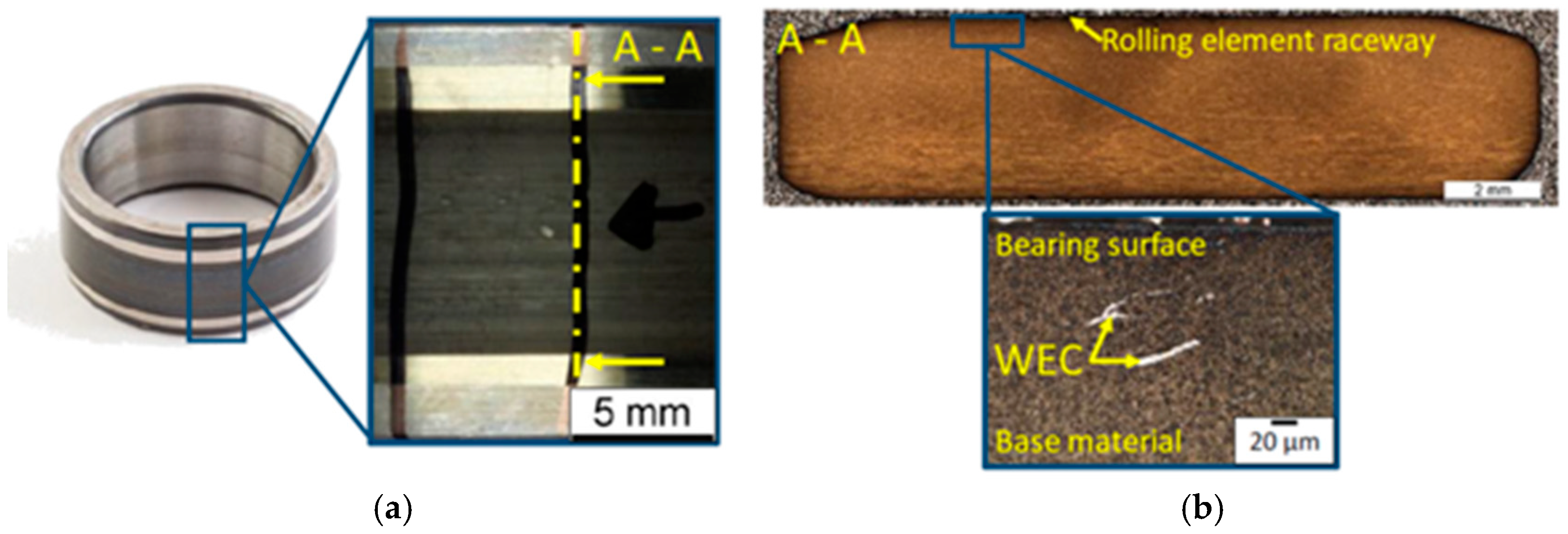
In recent years, the generation of white etching cracks has been observed to be related to the electrical bearing discharge [7]. Hydrogen atoms or hydrogen ions are formed in the lubricating grease/oil due to the generation of higher temperatures as a result of electrical discharge across the bearing of an electric motor. This makes the bearing materials fragile [81]. This results in local stress accumulation, which eventually causes cracks in the material. Additionally, the study suggests that this kind of defect is likely to occur when the bearings are loaded statically rather than dynamically. The bearing currents’ peak magnitude value is a key factor in the development of white etching cracks. The higher value of direct currents or alternating currents may result in the premature failure of the bearings due to the formation of white etching cracks in the oil or grease-lubricated bearings [82] (as shown in Figure 9). It is found that the cracks that are generated in a central inclusion are thereafter extended in different directions [83].

3.5. Dielectric Breakdown and Thermochemical Degradation of Lubricants Lubricant Degradation

Generally, the function of lubricants is to prevent metal-to-metal contact with a lubricating film. However, bearing currents flow within the bearing when the shaft voltage across it (as determined by the CMV) is higher than the threshold voltage of the lubricating film. This current generally flows through a gap between the balls and the raceway of motor bearings and decreases the lubricating film thickness, which creates very high localized heating in the surrounding environment. This thermal process causes the evaporation of lubricating oil components, which eventually ruins the lubricating grease and is considered the primary cause of the grease components’ deterioration [84].
Practically, the lubricating greases are chemically inert in nature, but the bearing currents and the shaft voltages offer the required potential and energy for the chemical reactions to occur, providing acceleration to the degradation process of the lubricants [2]. This bearing current reduces the efficiency, capabilities, and life of the lubricant and increases the friction and vibration within the bearing’s components, which eventually raises the bearing’s temperature, causing overloading and bearing failure [85]. Additionally, it is observed that there is a reduction in the dielectric strength of a lubricant, which has gone through the electric discharge breakdown [7]. Hence, the lubricating grease of the bearings must be such that it should prevent degradation from the bearing currents and the bearing wear [86]. The degradation of the lubricating grease at different voltages after 500 h of operation is shown in Figure 10.
The localized damage such as pitting and fluting on bearing surfaces affects both the vibration signatures and thermal behavior of the bearings. As the EDMS currents flow through the bearing, they generate micro-damage that alters the mechanical integrity and surface roughness of the bearing components, leading to increased vibration levels detectable by condition monitoring equipment [88]. Furthermore, the electrical currents raise localized temperatures in the bearing zone, which can exacerbate lubricant degradation and reduce oil film thickness, thereby intensifying wear and accelerating thermal buildup [89]. Experimental studies have demonstrated that increased bearing voltage correlates with rises in temperature due to the combined effect of electrical discharge heating and frictional losses caused by the evolving surface damage [90]. This thermal rise affects lubricant viscosity and film formation, compounding the bearing’s susceptibility to mechanical degradation and increasing vibration amplitudes. Additionally, the dynamic interaction between bearing current-induced damage and operational parameters such as load and speed modulates both electromagnetic and mechanical responses, thereby influencing measurable vibration frequencies and temperature profiles [90]. Monitoring these parameters simultaneously allows early detection of electrical bearing faults as sudden changes in vibration and temperature trends often accompany spikes in bearing voltage and current. Therefore, integrating electrical measurements of bearing current and voltage into vibration and temperature monitoring frameworks provides a more holistic diagnostic capability and enables more accurate prognostics under the specific operational conditions.

4. Measurement, Diagnostics, and Mitigation

4.1. Vibration and Signal-Based Diagnostics of Bearing Faults

The bearing current, causing EDMS currents within the bearing, damages the rolling components, raceways, and lubricants [91,92]. The signs of this damage caused by the bearing current, such as fluting, pitting, and burned grease, can be detected using tools like stethoscopes, vibration analysis, and grease testing. Vibration monitoring and analysis are well-established non-destructive techniques to diagnose problems in electric motors [93]. They work on the principle that a healthy machine has a specific vibration pattern and any variation from this vibration pattern may reveal potential faults. Typically, a healthy bearing does not vibrate much. However, when worn or damaged, the bearing’s vibration characteristics change and the overall vibration level increases.
When a bearing is defective, a series of impulses is generated as the rolling elements move across the defect on the bearing raceway, defining the vibration response of a defective bearing. The frequency of the generated impulses is termed the Characteristic Defect Frequency (CDF), and it is influenced by various factors such as the geometry of motor bearings, rotational speed, and the place where the defects are present on the bearing surface. Typically, four distinct types of Characteristic Defect Frequencies (CDFs) are commonly observed in ball bearings. These include Fundamental Train Frequency (FTF), Ball Pass Frequency Inner (BPFI), Ball Pass Frequency Outer (BPFO), and Ball Spin Frequency (BSF). Each of these frequencies is associated with specific types of defects in the cage, rolling elements, inner race, and outer race, respectively. The formulas for determining these CDFs for FTF, BSF, BPFI, and BPFO are as provided in Equations (9)–(12), respectively [94].
Fundamental   Train   Frequency :   F T F = f 2 1 d D cos θ
Ball   Spin   Frequency :   B S F = D 2 d f 1 d D cos θ 2
Ball   Pass   Frequency   Inner :   B P F I = Z 2 f 1 + d D cos θ
Ball   Pass   Frequency   Outer :   B P F O = Z 2 f 1 d D cos θ
where f represents the rotational speed of the motor shaft (RPS), Z represents the total number of rolling elements or balls, d represents the diameter (in millimeters) of the rolling elements, D represents the pitch diameter (in millimeters), and θ represents the contact angle (in degrees). A bearing should not produce Characteristic Defect Frequencies (CDFs). The magnitude of these CDFs signifies the severity of the defect. Due to noise, extracting the features from these signals is difficult. Therefore, researchers are actively striving to advance signal-processing methods to effectively utilize the information contained within the signal.
The initial research on signal processing techniques concerning bearings was relatively straightforward, focusing primarily on computing statistical parameters like mean, root mean square value, kurtosis, skewness, etc. The time-domain vibration signal gives limited information about the bearing condition [95]. However, it can be applied to trending, where an increase in the vibration level indicates a deteriorating machine condition. Measurement of overall vibration is an appropriate starting point for fault detection, but it may be unable to indicate precisely where the fault is and whether it is due to wear, unbalance, or misalignment. To find the type of faults and the exact location of the fault, the frequency analysis is used. The time-domain methods do not capture the frequency information embedded within the signal. Therefore, frequency information from defect-modulated signals has been extracted using both frequency-domain and time-frequency domain techniques, including Wigner–Ville distribution, Short-Time Fourier Transform, and Fast Fourier Transform (FFT).
Among these, the FFT is a widely used frequency domain technique for converting time-domain signals into frequency spectra [96]. However, more dominant frequencies from various machine components can hinder the identification of CDFs in the frequency spectrum. The high frequency resonance technique (or envelope analysis) is a more specialized frequency technique that analyses vibration signals at high frequencies to detect early faults in bearings [97]. However, the frequency analysis might not be able to capture the transient or non-stationary events, limiting its effectiveness in capturing intermittent faults or irregular patterns in the vibration signals [96].
Integration of the time domain and frequency domain techniques has become more popular as a result of recognizing the limitations of time-domain and frequency-domain analyses. One prominent technique in the time–frequency domain is the Short Time Fourier Transform, which allows for localizing frequency information within specific time intervals [98]. The advantage of localization frequency information is capturing transient events and dynamic changes in vibration signals. However, despite its merits, the STFT’s main drawback lies in the trade-off between time and frequency resolution. The frequency resolution decreases as the window size changes to capture localized events. Another technique known as wavelet analysis has been created to address the challenge of time-frequency resolution. Wavelet analysis techniques provide a multi-resolution approach, simultaneously capturing both low and high-frequency information [99]. However, the wavelet analysis technique is unsuitable for non-linear signals [100].
Most of the real-life processes generate non-stationary and nonlinear signals [101]. The Hilbert–Huang Transform is a powerful signal processing technique designed to analyze nonlinear and non-stationary signals [102]. Hilbert Spectral Analysis and Empirical Mode Decomposition are the two primary elements of the Hilbert–Huang Transform. The first stage of the Hilbert–Huang Transform, known as the Empirical Mode Decomposition, involves breaking down a signal into its intrinsic mode functions. Using the Hilbert Transform, the instantaneous frequency and amplitude of each intrinsic mode function are calculated in the second step, known as Hilbert Spectral Analysis. The Hilbert Spectral Analysis provides a time-frequency distribution of the signal, enabling the identification of transient features and variations in frequency over time. The Empirical Mode Decomposition may suffer from mode mixing, where intrinsic mode functions can contain multiple frequencies [103]. The Ensemble Empirical Mode Decomposition is a continuation of Empirical Mode Decomposition that addresses mode mixing [104]. It involves adding white noise to an input signal to improve the decomposition.
Currently, there is no standard method or technique available for directly measuring bearing voltage and bearing currents in electric motors [63]. The rise in temperature of the bearing, the increase in vibration, or a change in the position of a thrust or a journal can be an indicator to detect the shaft voltage and bearing current. However, shaft voltages can be approximately measured at the shaft ends relative to the grounded motor frame. These voltages arise from mechanisms such as ground leakage currents, dielectric breakdown within the bearing, or asymmetric stray capacitances. To envision the magnitude of bearing voltage, for a 400 V, 15 kW induction motor driven by a PWM inverter, the voltages can peak at up to 8 V, while shaft end-to-end voltages can reach 2 V with pulse widths around 30 ns [105]. For medium-voltage motors, manufacturers generally recommend a 5 V limit for bearing voltage; however, no specific limit is defined for bearing or shaft voltages in machines operated with inverters [106]. Monitoring both the magnitude and frequency of these voltage spikes is important, as they provide information about damaging discharges that lead to pitting and fluting. A detailed analysis of shaft voltage characteristics offers early warning of electrical discharge damage and valuable insight into bearing degradation mechanisms. Though these are common symptoms associated with bearing currents and voltage, they may not always be reliable indicators of the presence of shaft voltage and bearing currents [74]. Various techniques for measuring shaft voltages have been compared in the literature [107], highlighting the need for improved methods to accurately detect and quantify these phenomena in electric motors.
Bearing temperature can also serve as a critical indicator of bearing health. Generally, bearing temperature remains stable and slightly above ambient levels under normal conditions [108]. Abnormal rises in temperature can signal degradation pathways such as lubricant starvation, contamination, excessive preload, or damage to rolling elements [109]. Rapid temperature spikes may indicate temporary overloads, while steady increases typically suggest progressive wear or damage [110]. The temperature rise in a bearing or a material can be measured by using an infrared camera [111,112,113,114]. For example, localized heat and pressure increases within damaged rolling elements can mirror the thermal and mechanical changes observed during decomposition events involving rapid pressure rises. The rate of temperature increase also provides diagnostic insight: steep rises point to rapid degradation, whereas gradual increases suggest slower wear processes. These thermal attributes provide valuable real-time indicators of bearing integrity and energy dissipation.

4.2. Electrical and Thermal Indicators of Bearing Health

Lubricant condition assessment through oil and grease analysis provides direct evidence of wear, degradation, and contamination, all of which are critical indicators of system health.
Oil Analysis: Increased concentrations of metallic wear particles such as iron, copper, and chromium, along with changes in particle morphology from fine debris to cutting wear or spherical forms, reveal specific wear mechanisms including abrasion, adhesion, or fatigue [115,116]. Significant deviations in viscosity from baseline values indicate lubricant degradation, oxidation, or contamination, compromising film thickness and load-carrying capacity, and accelerating wear [116,117]. The presence of contaminants such as water, dirt, or particulates promotes abrasive and corrosive wear, providing a quantifiable measure of environmental effects on system degradation [118]. Additionally, a rising acid number (AN) or declining base number (BN) reflects lubricant oxidation and additive depletion, both of which reduce the lubricant’s protective properties and increase the risk of wear and corrosion [119].
Grease Analysis: Grease degradation in EVs can be broadly classified into lubricant degradation, microbubble formation, and electrowetting phenomena [120]. Achieving low torque properties is considered critical for the success of greases in EV drivetrains [121]. In these applications, lubricant degradation—driven by combined thermal and electrical stresses—can increase the coefficient of friction, compromising efficiency and reliability [122]. Grease degradation is primarily influenced by oxidation, evaporation, and mechanical breakdown resulting from the energy input imposed during operation [123,124,125]. Chemical analyses of critical drivetrain bearings have revealed clear evidence of additive depletion, oil evaporation, and thickener degradation, consistent with broader findings in tribology. Conspicuously, even in conditions of significant oil loss, bearings have demonstrated the ability to operate at elevated temperatures under relatively light loads. To evaluate grease performance and degradation, various test methods exist, including anti-corrosion testing and advanced techniques such as gamma scattering for assessing grease film thickness, which has shown promising accuracy with measurement deviations below 4.19% under mixed oil conditions in pipelines. Similarly, the assessment of fat, oil, and grease (FOG) degradation requires careful consideration of parameters such as extraction efficiency, given the notable apparent degradation observed in sterile controls (18–50%) [126]. Recently, Lijesh et al. [127,128] introduced a contact angle-based approach as a practical method for characterizing grease degradation. The water contact angle on grease offers valuable insight into the grease’s condition, particularly its water resistance and surface integrity. A higher contact angle indicates a well-preserved grease with strong hydrophobicity, whereas a lower contact angle reflects reduced water repellence and increased susceptibility to degradation and contamination. In EV motor bearings, where grease functions both as a lubricant and as part of the dielectric barrier, mitigating electrical discharges, monitoring contact angle changes provide an effective means of tracking grease degradation. Exposure to electrical discharges, thermal cycling, and mechanical shear progressively alters grease composition through oxidation, additive depletion, and thickener break-down, leading to reduced hydrophobicity and a declining contact angle. By establishing baseline measurements on fresh grease and periodically analyzing in-service samples, these trends can be tracked, offering early warning of degradation. A declining contact angle may signal heightened risk of water ingress, contamination, and accelerated wear conditions linked to pitting, fluting, and elevated vibration levels. Thus, contact angle analysis represents a simple yet powerful tool for monitoring grease condition in EV applications and supporting predictive maintenance strategies.

4.3. Lubricant Condition Monitoring and Grease Degradation Assessment

The IEEE112 mentions that the shunt current method may not be suitable for measuring shaft voltage because it generates a minimal impedance path between the ends of the shaft, which practically does not reflect the actual bearing current. Therefore, it is impractical to detect and recognize the value of bearing currents if there is no installed device for the measurement in the machines [63]. With the Rogowski coil installed around the shaft of a motor, the actual shaft current can be measured along with the circulating currents at high frequency [129]. This method is inappropriate for use in the field and requires a more sophisticated motor preparation. However, ABB uses the Rogowski coil to monitor ground currents linked to the higher value of dv/dt on inverter-fed machines [130].
A straightforward method of measuring the shaft voltage (with high bandwidth) is by using the “AEGIS Shaft Voltage Probe”, which makes use of the shaft brushes (in close proximity to the bearing). The majority of high-frequency bearing current measurement techniques are invasive, requiring appropriate preparation of the motor [107]. Electrical insulation is typically used to keep the motor and frame apart. After that, the insulation is shortened using a low-impedance wire setup and the wire current is measured. This method gives only an estimate of the bearing currents [64]. Since the bearings will depend on the motor size and the applications for which it is being used, the harmful bearing current value is, therefore, difficult to estimate. Hence, the apparent bearing current density (Jb) is described, and its value of less than 0.8 A/mm2 is considered to be safe for bearing life [131].
Nowadays, measurement techniques such as non-intrusive radio frequency are gaining popularity for high-frequency bearing current measurements [132,133]. This method operates under the assumption that the energy is released in the vicinity of the machines during the high-frequency discharge pulse. Using a specific time frame and a defined threshold value, the radio-frequency method counts the number of pulses radiated and received. The pulse count indicates how well the bearings can withstand high-frequency discharge currents and is called the Discharge Activity [132]. The manufacturer, SKF, offers an electric discharge detector pen for counting the number of electrical discharges if the high-frequency discharge voltages are found to be suspected in one or more bearings, which, therefore, can be useful in estimating the severity and degree of the defects in a bearing. Therefore, depending on the purposes and uses of the electric motors, one or more measurement techniques can be employed to keep an eye on the existence of bearing currents and shaft voltages within the motors. Figure 11 displays the various external points necessary for the measurements of the system.

4.4. Mitigation or Solution to the Bearing Currents Problem

Mitigating the electric discharge current effects in electric motors becomes essential to increase the bearing service life, prevent the motor from experiencing bearing currents in different operating conditions, and gain long-term stability [2]. The solution to the problems originating from the current flow in bearings can be classified into two categories [67] after analyzing both the industry and the test bench. The first kind will concentrate on the bearing current path, whereas the second kind will concentrate on the bearing current’s origin, i.e., using an inverter or variable frequency drive (VFD) to power the electric motors [134,135].
The first category uses shaft grounding brushes across one of the motor bearings, insulated bearings, electrostatically shielded rotor shafts, high-frequency bonding straps, ceramic/hybrid ceramic bearings, and coupling insulation for protecting the load. Because of the coated (insulated) layer on the bearing surface, insulated bearings can help in decreasing the circulating bearing currents, while the ceramic/hybrid ceramic bearings can be used to break the path of bearing currents. A more detailed discussion of the first kind is given in [34], where it is noted that, depending on the dominant path in a given application, the mitigation and reduction of the harmful bearing currents will vary.
The second category aims to mitigate or reduce the common-mode voltages, which are considered the primary source for high-frequency bearing currents in electric motors. To mitigate or reduce the CMV, one can use common-mode chokes, sinusoidal filters, shielded cables, inverter output filters (dv/dt filters), and common-mode filters [63]. The research in [37] shows no influence of switching speeds on shaft voltage because of the filtering behavior of the machine impedance. However, with an increase in dv/dt value, there is an increase in the bearing current due to the higher value of common-mode currents. Although there is a decrease in switching losses with an increase in dv/dt value, it also increases the common-mode currents, which lead to stresses in the insulation system.
In [136,137], various methods were discussed for mitigating and reducing the shaft voltage and the bearing current. The literature shows that the use of conductive brushes is the most common way for current reduction. One approach built a minimal-impedance circuit between the stator and the rotor, rapidly discharging the bearing capacitances. This minimal contact resistance is very important since the resistance may increase significantly because of the occurrence of corrosion, or maybe when this brush contacts the lubrication grease/oil. The conductive lubricating grease works similarly within the bearings; however, there is significant concern regarding the grease’s long-term stability [136]. Achieving reduced shaft voltage involves utilizing a conductive brush with low resistance. This holds true for conductive grease/oil as well, as low resistance plays a crucial role in generating high inductive bearing current when employing conductive grease in the bearings of electric motors. This results in the rise of the apparent power of the bearing, which can be seen in a relatively low value of brush resistance as well. The experiment shows that using conductive grease rapidly reduces both shaft voltages and bearing currents. However, the increase in the magnitude of shaft voltages is noticed when an insulated bearing is used in motors due to the decrease in the effective capacitance of the bearing [37].
As discussed above, there are several methods or techniques that, when implemented, will become useful in mitigating or reducing the harmful shaft voltage and bearing current. However, which method will be more appropriate will depend on the uses and applications of the electrical machinery. To provide a stronger and more intuitive comparison of existing mitigation strategies for bearing current-related issues in electric vehicle (EV) motors, Table 1 summarizes commonly used methods. These approaches are broadly categorized into two groups: (i) those that interrupt or break the bearing current path and (ii) those that reduce or eliminate the source of the current, such as inverter-induced common-mode voltage. The table outlines each method’s core functionality, key advantages, and limitations, offering a practical perspective for selecting suitable solutions based on specific operating conditions and system requirements.

5. Influence of Mechanical and Electrical Properties of Lubricants on Bearing Current and Shaft Voltage

The electrical properties of lubricating grease in bearings can have a big impact on reducing and eliminating the current flow through the bearings within the electric motors of EVs. In the case of non-conductive lubrication, the bearing rollers detach from the bearing raceway as the electric motor operates at an elevated speed. The detachment creates a bearing voltage due to a non-zero CMV, leading to a low capacitive bearing current [24]. When the voltage across the motor bearings surpasses the threshold voltage of a non-conductive lubricating oil film, it triggers an electrical discharge within the bearing, leading to excessive heating of the bearing surfaces due to arcing. This significant heating leads to bearing surface melting, which results in different types of surface defects in bearing [11]. Hence, lubricating grease with non-conducting properties directly influences the bearing currents and shaft voltage in electric motors.
The experimental approach shows that lubricating grease with enhanced electrical conductivity reduces fluting damage in bearings, as in the case of conducting grease, the electrical current density in the rolling contact area is reduced as a result of the creation of electrical channels. In contrast, this phenomenon is absent in insulating grease [70]. The magnetic flux density (i.e., the passing of current) is observed on the bearing surfaces in the case of lubricating grease with lower resistance [137]. Because of a conductive lubricant, the current can flow easily from the inner raceway to the rollers and then again to the outer raceway, causing heating action on the rollers and the raceways and making the bearing act like an electrically ohmic resistor. It is seen in [136] that the value of shaft voltage is lower for conductive lubricating grease than non-conductive lubricating grease; however, the quality of both kinds of lubricants is found to be similar. The paper [138] shows that as the lubricating grease deteriorates, the amplitude value of high-frequency dv/dt rises.
The actual state of roller bearings is determined by factors like radial and axial load, rotational speed, temperature, and lubricant properties (determined using the thickness of the lubricating film). Nowadays, the breakdown voltages of lubricating oil films are determined by assessing the minimum lubricating film thickness and the dielectric properties of the lubricating grease. A correlation has been observed between the rise in bearing temperature due to EDMS currents and a subsequent decrease in the lubricant viscosity within the bearing. The decline in viscosity reduces the oil film thickness, consequently lowering the breakdown voltage of the lubricating film [139]. Therefore, achieving a higher breakdown voltage necessitates using an optimal lubricating film thickness. The rotor speed and bearing temperature can affect dielectric strength and lubricating film thickness. It is observed that lubricating grease’s dielectric strength tends to increase with temperature but decreases with rotor speed. Meanwhile, the thickness of the lubricating film grows with higher rotor speed [7]. Chiou et al. [69] found that the insulating effect of the lubricating film decreases with increasing concentration of the MoS2 (a component found in lubricating grease to enhance wear characteristics) and the current amplitude.
From the above discussion, it is important to note that lubricant dielectric strength plays a critical role in delaying film breakdown under high shaft voltages common in EV motors. However, this benefit diminishes as operating temperatures rise, which can lower dielectric thresholds. Similarly, controlled electrical conductivity—achieved through carefully formulated additives such as carbon nanoparticles—could help disperse minor currents, reducing localized erosion. However, this must be balanced to avoid creating unintended conductive pathways. The relationship between lubricant electrical breakdown and characteristic damage morphologies (e.g., frosting and fluting) offers valuable guidance for the design of next-generation greases tailored to EV applications. Such formulations should aim to combine high dielectric strength, thermal stability, and calibrated conductivity to effectively mitigate EDM-induced bearing failures.
Finally, Table 2 provides a comparative summary of key studies, emphasizing their focus, contributions, and limitations related to bearing currents, lubrication, mitigation, and diagnostics in electric vehicle motor applications.

6. Conclusions

This review systematically examined the phenomena of bearing current and shaft voltage in electric vehicle (EV) motors, with a particular emphasis on electric discharge material spalling (EDMS) currents. This study highlighted key damage mechanisms—such as pitting, fluting, and lubricant degradation—and underscored the role of lubricant properties in suppressing current-induced failures.
Given the absence of standardized methods for directly measuring bearing currents, this review evaluated various indirect diagnostic approaches, including vibration analysis, temperature monitoring, and lubricant condition assessment. The importance of the dielectric strength, conductivity, and film stability of lubricants in mitigating current flow was emphasized.
This review also outlined emerging trends such as improved inverter designs, advanced non-intrusive diagnostic tools, and the development of conductive and nanoparticle-enhanced lubricants. These align with the broader aim of developing integrated, real-time monitoring and mitigation strategies. In summary, this study achieved its objective by synthesizing the current understanding of bearing current mechanisms, lubricant interactions, and mitigation methods. It offers actionable insights to guide future research and enhance the reliability of EV drivetrain systems.

Author Contributions

Conceptualization, data curation, writing original draft: R.L., S.K.M., D.R., P.S. and V.E.; writing—review and editing: P.S., V.E. and L.K., visualization, supervision, P.S. and V.E.; Project administration, Funding acquisition, V.E. All authors have read and agreed to the published version of the manuscript.

Funding

This research is supported by Indian Institute Technology, Madras with grant number: RF24250535MERFER009005.

Data Availability Statement

The data presented in this review are derived from previously published literature.

Conflicts of Interest

The authors declare no conflicts of interest.

Abbreviations

ACAlternating Current
BEVBattery Electric Vehicle
BPFIBall Pass Frequency Inner
BPFOBall Pass Frequency Outer
BSFBall Spin Frequency
BVRBearing Voltage Ratio
CDFCharacteristics Defect Frequency
CFRPCarbon Fiber-Reinforced Plastic
CMVCommon Mode Voltage
EDMSElectric Discharge Material Spalling Current
EMIElectromagnetic Interference
EVElectric Vehicle
FCEVFuel Cell Electric Vehicle
FFTFast Fourier Transform
FTFFrequency Train Frequency
HEVHybrid Electric Vehicle
ICInternal Combustion
IGBTInsulated Gate Bipolar Transistor
MOSFETMetal-Oxide-Semiconductor Field-Effect Transistors
PWMPulse Width Modulation
PHEVPlug-In Hybrid Electric Vehicle
RPSRevolution Per Second
SEMScanning Electron Microscope
SEVSolar Electric Vehicle
VFDVariable Frequency Drive
WECWhite Etching Current

References

  1. Chan, C.C. The state of the art of electric, hybrid, and fuel cell vehicles. Proc. IEEE 2007, 95, 704–718. [Google Scholar] [CrossRef]
  2. He, F.; Xie, G.; Luo, J. Electrical bearing failures in electric vehicles. Friction 2020, 8, 4–28. [Google Scholar] [CrossRef]
  3. Guo, L.; Mol, H.; Nijdam, T.; de Vries, L.; Bongaerts, J. Study on the electric discharge behaviour of a single contact in EV motor bearings. Tribol. Int. 2023, 187, 108743. [Google Scholar] [CrossRef]
  4. Ahmed Abdalglil Mustafa, W.; Dassenoy, F.; Sarno, M.; Senatore, A. A review on potentials and challenges of nanolubricants as promising lubricants for electric vehicles. Lubr. Sci. 2022, 34, 1–29. [Google Scholar] [CrossRef]
  5. Pei, T.; Zhang, H.; Hua, W.; Zhang, F. Comprehensive Review of Bearing Currents in Electrical Machines: Mechanisms, Impacts, and Mitigation Techniques. Energies 2025, 18, 517. [Google Scholar] [CrossRef]
  6. Chan, C.C.; Bouscayrol, A.; Chen, K. Electric, hybrid, and fuel-cell vehicles: Architectures and modeling. IEEE Trans. Veh. Technol. 2009, 59, 589–598. [Google Scholar] [CrossRef]
  7. Ma, J.; Xue, Y.; Han, Q.; Li, X.; Yu, C. Motor bearing damage induced by bearing current: A Review. Machines 2022, 10, 1167. [Google Scholar] [CrossRef]
  8. Bleger, A.; Leighton, M.; Morris, N. Automotive e-motor bearing electrical discharge phenomena: An experimental and numerical investigation. Tribol. Int. 2024, 191, 109140. [Google Scholar] [CrossRef]
  9. Lee, P.M.; Sanchez, C.; Frazier, C.; Velasquez, A.; Kostan, T. Tribological evaluation of electric vehicle driveline lubricants in an electrified environment. Front. Mech. Eng. 2023, 9, 1215352. [Google Scholar] [CrossRef]
  10. Song, C.; Ren, Y.; Huang, Q.; Zhang, Y.; Li, Y.; Cheng, J.; Pang, X.; Zhang, Y. Effect of shaft voltage on electric damage of GCr15 bearing material. Tribol. Int. 2024, 200, 110139. [Google Scholar] [CrossRef]
  11. Busse, D.; Erdman, J.; Kerkman, R.J.; Schlegel, D.; Skibinski, G. Bearing currents and their relationship to PWM drives. IEEE Trans. Power Electron. 1997, 12, 243–252. [Google Scholar] [CrossRef]
  12. Alger, P.; Samson, H. Shaft currents in electric machines. Trans. Am. Inst. Electr. Eng. 2009, 43, 235–245. [Google Scholar]
  13. Kalaiselvi, J.; Srinivas, S. Bearing currents and shaft voltage reduction in dual-inverter-fed open-end winding induction motor with reduced CMV PWM methods. IEEE Trans. Ind. Electron. 2014, 62, 144–152. [Google Scholar] [CrossRef]
  14. Busse, D.; Erdman, J.; Kerkman, R.; Schlegal, D.; Skibinski, G. Characteristics of shaft voltage and bearing currents. IEEE Ind. Appl. Mag. 1997, 3, 21–32. [Google Scholar] [CrossRef]
  15. Son, D.W.; Zhang, T.; Lee, G. Study on Electrical Pitting Prevention Device of a Rotating Shaft Using Automatic Control Potential Balancing. Materials 2022, 15, 4510. [Google Scholar] [CrossRef]
  16. Schneider, V.; Behrendt, C.; Höltje, P.; Cornel, D.; Becker-Dombrowsky, F.M.; Puchtler, S.; Gutiérrez Guzmán, F.; Ponick, B.; Jacobs, G.; Kirchner, E. Electrical bearing damage, a problem in the nano-and macro-range. Lubricants 2022, 10, 194. [Google Scholar] [CrossRef]
  17. Oh, H.W.; Willwerth, A.H. New motor design with conductive micro fiber shaft grounding ring prevents bearing failure in PWE inverter driven motors. In Proceedings of the 2007 Electrical Insulation Conference and Electrical Manufacturing Expo, Nashville, Tennessee, 22–24 October 2007; IEEE: Piscataway, NJ, USA, 2007; pp. 240–246. [Google Scholar]
  18. Tawfiq, K.B.; Güleç, M.; Sergeant, P. Bearing current and shaft voltage in electrical machines: A comprehensive research review. Machines 2023, 11, 550. [Google Scholar] [CrossRef]
  19. Prudhom, A.; Antonino-Daviu, J.; Razik, H.; Climente-Alarcon, V. Time-frequency vibration analysis for the detection of motor damages caused by bearing currents. Mech. Syst. Signal Process. 2017, 84, 747–762. [Google Scholar] [CrossRef]
  20. Chen, S.; Lipo, T.A.; Fitzgerald, D. Source of induction motor bearing currents caused by PWM inverters. IEEE Trans. Energy Convers. 2002, 11, 25–32. [Google Scholar] [CrossRef]
  21. Qiu, J.; He, Y.; Xu, L.; Jiao, Q. A Novel SVPWM Technique for Leakage Current Reduction and Neutral-Point Voltage Balance in Transformerless Three-Level Inverters. In Proceedings of the 2020 4th International Conference on HVDC (HVDC), Xi’an, China, 6–9 November 2020; IEEE: Piscataway, NJ, USA, 2020; pp. 560–565. [Google Scholar]
  22. Heino, T. Bearing Currents and Their Mitigation in Frequency Converter-Driven Induction Motors. Bachelor’s Thesis, Electrical Engineering, Vaasa, Finland, 2014. [Google Scholar]
  23. Plazenet, T.; Boileau, T.; Caironi, C.; Nahid-Mobarakeh, B. An overview of shaft voltages and bearing currents in rotating machines. In Proceedings of the 2016 IEEE Industry Applications Society Annual Meeting, Portland, ON, USA, 2–6 October 2016; IEEE: Piscataway, NJ, USA, 2016; pp. 1–8. [Google Scholar]
  24. Wang, F. Motor shaft voltages and bearing currents and their reduction in multilevel medium-voltage PWM voltage-source-inverter drive applications. IEEE Trans. Ind. Appl. 2000, 36, 1336–1341. [Google Scholar] [CrossRef]
  25. Im, J.-H.; Kang, J.-K.; Lee, Y.-K.; Hur, J. Shaft voltage elimination method to reduce bearing faults in dual three-phase motor. IEEE Access 2022, 10, 81042–81053. [Google Scholar] [CrossRef]
  26. Liu, S.; Lv, J.; Yang, Z.; Kuang, L.; Zhao, L.; Liu, C. The discharge characteristics and damages in the EV motor bearings: Influenced by the rotational speeds and lubricating oil viscosities. Wear 2025, 571, 205863. [Google Scholar] [CrossRef]
  27. Prashad, H. Appearance of craters on track surface of rolling element bearings by spark erosion. Tribol. Int. 2001, 34, 39–47. [Google Scholar] [CrossRef]
  28. Chin, J.-W.; Kim, D.-J.; Park, S.; Yu, T.; Jung, H.-C. Sensitivity Analysis on Shaft Voltage according to Variables of Inverter and Motor for Electric Vehicle Powertrain. In Proceedings of the 2023 IEEE Energy Conversion Congress and Exposition (ECCE), Nashville, TN, USA, 29 October 2023; IEEE: Piscataway, NJ, USA, 2023. [Google Scholar]
  29. Jonjo, E.R.; Ali, I.; Megahed, T.F.; Nassef, M.G. Mitigation of Electrical Discharge Damage in Electric Vehicle Bearings: Comparative Study of Multi-Walled Carbon Nanotubes and Alumina Nanoparticles in Lubricating Grease. Vehicles 2025, 7, 19. [Google Scholar] [CrossRef]
  30. Song, Y.; Yan, P.; Zhao, W.; Sha, T.; Dai, Z.; Li, S.; Gu, H.; Wang, X. Finite Element Simulation Method for Fretting Wear Considering Double-Side Wear Behavior. Tribol. Lett. 2025, 73, 57. [Google Scholar] [CrossRef]
  31. Notay, R.S. A Brief Review on the Tribological Effects of Electrically Induced Bearing Damage. J. Tribol. 2025, 147, 1–27. [Google Scholar] [CrossRef]
  32. Thorsen, O.; Dalva, M. Failure identification and analysis for high voltage induction motors in petrochemical industry. In Proceedings of the Conference Record of 1998 IEEE Industry Applications Conference. Thirty-Third IAS Annual Meeting (Cat. No. 98CH36242), St. Louis, MO, USA, 12–15 October 1998; IEEE: Piscataway, NJ, USA, 1998. [Google Scholar]
  33. Thorsen, O.V.; Dalva, M. A survey of faults on induction motors in offshore oil industry, petrochemical industry, gas terminals, and oil refineries. IEEE Trans. Ind. Appl. 2002, 31, 1186–1196. [Google Scholar] [CrossRef]
  34. Schiferl, R.; Melfi, M. Bearing current remediation options. IEEE Ind. Appl. Mag. 2004, 10, 40–50. [Google Scholar] [CrossRef]
  35. Tong, W. Mechanical Design and Manufacturing of Electric Motors; CRC Press: Boca Raton, FL, USA, 2022. [Google Scholar]
  36. Park, J.-K.; Jeong, C.-L.; Bianchi, N.; Hur, J. Frame-to-shaft voltage and end-to-end shaft voltage analysis according to eccentricity in IPMSMs. In Proceedings of the 2018 IEEE Energy Conversion Congress and Exposition (ECCE), Portland, ON, USA, 23–27 September 2018; IEEE: Piscataway, NJ, USA, 2018. [Google Scholar]
  37. Quabeck, S.; Grau, V.; De Doncker, R.W. Modeling and mitigation of bearing currents in electrical traction drives. In Proceedings of the 2020 23rd International Conference on Electrical Machines and Systems (ICEMS), Hamamatsu, Japan, 24–27 November 2020; IEEE: Piscataway, NJ, USA, 2020. [Google Scholar]
  38. Shami, U.T.; Akagi, H. Identification and discussion of the origin of a shaft end-to-end voltage in an inverter-driven motor. IEEE Trans. Power Electron. 2009, 25, 1615–1625. [Google Scholar] [CrossRef]
  39. Eull, M.; Preindl, M. A soft switching inverter minimizing bearing currents in 800V electric vehicle drives. In Proceedings of the 2021 IEEE 13th International Symposium on Diagnostics for Electrical Machines, Power Electronics and Drives (SDEMPED), Dallas, TX, USA, 22–25 August 2021; IEEE: Piscataway, NJ, USA, 2019. [Google Scholar]
  40. Krein, P.T. Electrostatic discharge issues in electric vehicles. IEEE Trans. Ind. Appl. 2002, 32, 1278–1284. [Google Scholar] [CrossRef]
  41. Abu-Rub, H.; Bayhan, S.; Moinoddin, S.; Malinowski, M.; Guzinski, J. Medium-voltage drives: Challenges and existing technology. IEEE Power Electron. Mag. 2016, 3, 29–41. [Google Scholar] [CrossRef]
  42. Zhu, J.; Kim, H.; Chen, H.; Erickson, R.; Maksimović, D. High efficiency SiC traction inverter for electric vehicle applications. In Proceedings of the 2018 IEEE Applied Power Electronics Conference and Exposition (APEC), San Antonio, TX, USA, 26–30 March 2018; IEEE: Piscataway, NJ, USA, 2018. [Google Scholar]
  43. Arora, T.; Renge, M.; Aware, M. Effects of switching frequency and motor speed on common mode voltage, common mode current and shaft voltage in PWM inverter-fed induction motors. In Proceedings of the 2017 12th IEEE Conference on Industrial Electronics and Applications (ICIEA), Siem Reap, Cambodia, 18–20 June 2017; IEEE: Piscataway, NJ, USA, 2017. [Google Scholar]
  44. Ronanki, D.; Perumal, P. A SVPWM for reduction in common mode and bearing currents applied to diode clamped three-level inverter fed induction motor. In Proceedings of the 2016 IEEE International Power Electronics and Motion Control Conference (PEMC), Varna, Bulgaria, 25–28 September 2016; IEEE: Piscataway, NJ, USA, 2017. [Google Scholar]
  45. Kalaiselvi, J.; Srinivas, S. Bearing current profiles in a 3-phase VSI fed induction motor drive using a simplified measurement approach. In Proceedings of the 2012 IEEE International Conference on Power Electronics, Drives and Energy Systems (PEDES), Mangalore, India, 18–21 December 2012; IEEE: Piscataway, NJ, USA, 2012. [Google Scholar]
  46. Loh, P.C.; Holmes, D.G.; Fukuta, Y.; Lipo, T.A. Reduced common-mode modulation strategies for cascaded multilevel inverters. IEEE Trans. Ind. Appl. 2003, 39, 1386–1395. [Google Scholar]
  47. Gupta, A.K.; Khambadkone, A.M. A space vector modulation scheme to reduce common mode voltage for cascaded multilevel inverters. IEEE Trans. Power Electron. 2007, 22, 1672–1681. [Google Scholar] [CrossRef]
  48. Espina, J.; Ortega, C.; De Lillo, L.; Empringham, L.; Balcells, J.; Arias, A. Reduction of output common mode voltage using a novel SVM implementation in matrix converters for improved motor lifetime. IEEE Trans. Ind. Electron. 2014, 61, 5903–5911. [Google Scholar] [CrossRef]
  49. Hussain, H.A.; Toliyat, H.A. Reduction of shaft voltages and bearing currents in five-phase induction motors. In Proceedings of the 2012 IEEE Energy Conversion Congress and Exposition (ECCE), Raleigh, NC, USA, 15–20 September 2012; IEEE: Piscataway, NJ, USA, 2012. [Google Scholar]
  50. Erdman, J.M.; Kerkman, R.J.; Schlegel, D.W.; Skibinski, G.L. Effect of PWM inverters on AC motor bearing currents and shaft voltages. IEEE Trans. Ind. Appl. 2002, 32, 250–259. [Google Scholar] [CrossRef]
  51. Adabi, J.; Zare, F.; Ledwich, G.; Ghosh, A. Leakage current and common mode voltage issues in modern AC drive systems. In Proceedings of the 2007 Australasian Universities Power Engineering Conference, Perth, Australia, 9–12 December 2007; IEEE: Piscataway, NJ, USA, 2007. [Google Scholar]
  52. Muetze, A.; Binder, A. Practical rules for assessment of inverter-induced bearing currents in inverter-fed AC motors up to 500 kW. IEEE Trans. Ind. Electron. 2007, 54, 1614–1622. [Google Scholar] [CrossRef]
  53. Han, P.; Heins, G.; Patterson, D.; Thiele, M.; Ionel, D.M. Evaluation of Bearing Voltage Reduction in Electric Machines by Using Insulated Shaft and Bearings. In Proceedings of the 2020 IEEE Energy Conversion Congress and Exposition (ECCE), Detroit, MI, USA, 11–15 October 2020; pp. 5584–5589. [Google Scholar]
  54. Xiao, Z.; Hu, M.; Chen, S.; Cao, K. Bearing electrical-erosion damage in electrical drive systems: A review. IEEE Trans. Transp. Electrif. 2023, 7, 3428–3442. [Google Scholar] [CrossRef]
  55. Puchtler, S.; Maier, R.; Kuhn, M.; Burkhardt, Y. The Influence of Load and Speed on the Initial Breakdown of Rolling Bearings Exposed to Electrical Currents. Lubricants 2023, 12, 1. [Google Scholar] [CrossRef]
  56. von Jouanne, A.; Collin, R.; Stephens, M.; Phillips, B.; Chen, H.; Li, C.; Agamloh, E.; Yokochi, A. Development of Inverter Duty Motor Bearings for Si and SiC-Based Variable Frequency Drive Applications Including Advanced 4D Finite Element Modeling. In Proceedings of the 2021 IEEE Energy Conversion Congress and Exposition (ECCE), Vancouver, BC, Canada, 10–14 October 2021; IEEE: Piscataway, NJ, USA, 2021. [Google Scholar]
  57. Yang, M.; Cheng, Y.; Du, B.; Li, Y.; Wang, S.; Cui, S. Research on Analysis and Suppression Methods of the Bearing Current for Electric Vehicle Motor Driven by SiC Inverter. Energies 2024, 17, 1109. [Google Scholar] [CrossRef]
  58. Bechev, D.; Capan, R.; Gonda, A.; Sauer, B. Method for the investigation of the EDM breakdown voltage of grease and oil on rolling bearings. Bear World J. 2019, 4, 83–91. [Google Scholar]
  59. Lokhande, R. Development of a Novel Test Rig for Quantifying Motor Bearing Failures due to Electric Discharge Machining Current in EVs. In Department of Mechanical Engineering; Indian Institute of Technology Madras: Chennai, India, 2025; pp. 1–92. [Google Scholar]
  60. Beroual, A.; Khaled, U.; Mbolo Noah, P.S.; Sitorus, H. Comparative study of breakdown voltage of mineral, synthetic and natural oils and based mineral oil mixtures under AC and DC voltages. Energies 2017, 10, 511. [Google Scholar] [CrossRef]
  61. Gonda, A.; Capan, R.; Bechev, D.; Sauer, B. The influence of lubricant conductivity on bearing currents in the case of rolling bearing greases. Lubricants 2019, 7, 108. [Google Scholar] [CrossRef]
  62. Klenk, T.; Colineau, F.; Morgenstern, S. Conductive Simmerrings help prevent electrical discharge machining in modern electrical powertrains. Bear. World J. 2019, 4, 7–13. [Google Scholar]
  63. Plazenet, T.; Boileau, T.; Caironi, C.; Nahid-Mobarakeh, B. A comprehensive study on shaft voltages and bearing currents in rotating machines. IEEE Trans. Ind. Appl. 2018, 54, 3749–3759. [Google Scholar] [CrossRef]
  64. Chen, S.; Lipo, T.A. Circulating type motor bearing current in inverter drives. IEEE Ind. Appl. Mag. 1998, 4, 32–38. [Google Scholar] [CrossRef]
  65. Patro, B.D.K.; Suvin, P.; Dalimba, U.; Kreivaitis, R. Effect of temperature on tribological behavior of L–proline–based green deep eutectic solvents for Ti6Al4V interfaces: A study of novel potential lubricant. Tribol. Int. 2025, 208, 110667. [Google Scholar] [CrossRef]
  66. Asefi, M.; Nazarzadeh, J. Survey on high-frequency models of PWM electric drives for shaft voltage and bearing current analysis. IET Electr. Syst. Transp. 2017, 7, 179–189. [Google Scholar] [CrossRef]
  67. Mütze, A.; Binder, A. Don’t lose your bearings. IEEE Ind. Appl. Mag. 2006, 12, 22–31. [Google Scholar] [CrossRef]
  68. Chiou, Y.-C.; Lee, R.-T.; Lin, C.-M. Formation criterion and mechanism of electrical pitting on the lubricated surface under AC electric field. Wear 1999, 236, 62–72. [Google Scholar] [CrossRef]
  69. Lin, C.-M.; Chiou, Y.-C.; Lee, R.-T. Effect of MoS2 additive on electrical pitting mechanism of lubricated surface for Babbitt alloy/bearing steel pair under ac electric field. Wear 2004, 257, 833–842. [Google Scholar] [CrossRef]
  70. Suzumura, J. Prevention of electrical pitting on rolling bearings by electrically conductive grease. Q. Rep. RTRI 2016, 57, 42–47. [Google Scholar] [CrossRef]
  71. Kaufman, H.; Boyd, J. The conduction of current in bearings. ASLE Trans. 1959, 2, 67–77. [Google Scholar] [CrossRef]
  72. Prashad, H. Theoretical analysis of the effects of instantaneous charge leakage on roller tracks of roller bearings lubricated with high resistivity lubricants under the influence of electric current. J. Tribol. 1990, 112, 37–43. [Google Scholar] [CrossRef]
  73. Tischmacher, H.; Gattermann, S. Bearing currents in converter operation. In Proceedings of the The XIX International Conference on Electrical Machines-ICEM 2010, Rome, Italy, 6–8 September 2010; IEEE: Piscataway, NJ, USA, 2010. [Google Scholar]
  74. Costello, M.J. Shaft voltages and rotating machinery. IEEE Trans. Ind. Appl. 2002, 29, 419–426. [Google Scholar] [CrossRef]
  75. Ost, W.; De Baets, P. Failure analysis of the deep groove ball bearings of an electric motor. Eng. Fail. Anal. 2005, 12, 772–783. [Google Scholar] [CrossRef]
  76. Tischmacher, H.; Gattermann, S.; Kriese, M.; Wittek, E. Bearing wear caused by converter-induced bearing currents. In Proceedings of the IECON 2010-36th Annual Conference on IEEE Industrial Electronics Society, Glendale, AZ, USA, 7–10 November 2010; IEEE: Piscataway, NJ, USA, 2010. [Google Scholar]
  77. Raadnui, S.; Kleesuwan, S. Electrical pitting wear debris analysis of grease-lubricated rolling element bearings. Wear 2011, 271, 1707–1718. [Google Scholar] [CrossRef]
  78. Didenko, T.; Pridemore, W.D. Electrical fluting failure of a Tri-lobe roller bearing. J. Fail. Anal. Prev. 2012, 12, 575–580. [Google Scholar] [CrossRef]
  79. Safdarzadeh, O.; Farahi, A.; Binder, A.; Sezen, H.; Hofmann, J.P. WLI, XPS and SEM/FIB/EDS surface characterization of an electrically fluted bearing raceway. Lubricants 2024, 12, 148. [Google Scholar] [CrossRef]
  80. Liu, W. The prevalent motor bearing premature failures due to the high frequency electric current passage. Eng. Fail. Anal. 2014, 45, 118–127. [Google Scholar] [CrossRef]
  81. Romanenko, A.; Muetze, A.; Ahola, J. Effects of electrostatic discharges on bearing grease dielectric strength and composition. IEEE Trans. Ind. Appl. 2016, 52, 4835–4842. [Google Scholar] [CrossRef]
  82. Loos, J.; Bergmann, I.; Goss, M. Influence of high electrical currents on WEC formation in rolling bearings. Tribol. Trans. 2021, 64, 708–720. [Google Scholar] [CrossRef]
  83. Gould, B.; Greco, A.; Stadler, K.; Vegter, E.; Xiao, X. Using advanced tomography techniques to investigate the development of White Etching Cracks in a prematurely failed field bearing. Tribol. Int. 2017, 116, 362–370. [Google Scholar] [CrossRef]
  84. Romanenko, A.; Ahola, J.; Muetze, A. Influence of electric discharge activity on bearing lubricating grease degradation. In Proceedings of the 2015 IEEE Energy Conversion Congress and Exposition (ECCE), Montreal, QC, Canada, 20–24 September 2015; IEEE: Piscataway, NJ, USA, 2015. [Google Scholar]
  85. Mufazzal, S.; Muzakkir, S.; Khanam, S. On the importance of modeling ball raceway impact force for evaluating the plastic deformation at spall edge of rolling element bearing: Theoretical modeling. J. Vib. Eng. Technol. 2024, 12, 1309–1322. [Google Scholar] [CrossRef]
  86. Malec, D.; Bley, V.; Talbi, F.; Lalam, F. Contribution to the understanding of the relationship between mechanical and dielectric strengths of Alumina. J. Eur. Ceram. Soc. 2010, 30, 3117–3123. [Google Scholar] [CrossRef]
  87. Noguchi, S.; Kakinuma, S.-N.; Kanada, T. Measurement of direct current voltage causing electrical pitting. J. Adv. Mech. Des. Syst. Manuf. 2010, 4, 1084–1094. [Google Scholar] [CrossRef]
  88. Schoen, R.R.; Habetler, T.G.; Kamran, F.; Bartfield, R.G. Motor bearing damage detection using stator current monitoring. In Proceedings of the 1994 IEEE Industry Applications Society Annual Meeting, Denver, CO, USA, 2–5 October 1994; IEEE: Piscataway, NJ, USA, 1994. [Google Scholar]
  89. Huan, J.; Li, S.; Xia, Z.; Wang, Y.; Wang, W.; Shi, G. Experimental Study on Electric Corrosion Damage of Bearing and Solution. Proc. Inst. Mech. Eng. Part C J. Mech. Eng. Sci. 2022, 236, 10349–10358. [Google Scholar] [CrossRef]
  90. Joshi, A. Electrical Characterisations of Bearings. Ph.D. Thesis, Chalmers University of Technology, Göteborg, Sweden, 2019. (In Sweden). [Google Scholar]
  91. Park, J.-K.; Wellawatta, T.R.; Ullah, Z.; Hur, J. New equivalent circuit of the IPM-type BLDC motor for calculation of shaft voltage by considering electric and magnetic fields. IEEE Trans. Ind. Appl. 2016, 52, 3763–3771. [Google Scholar] [CrossRef]
  92. Han, P.; Heins, G.; Patterson, D.; Thiele, M.; Ionel, D.M. Modeling of bearing voltage in electric machines based on electromagnetic FEA and measured bearing capacitance. IEEE Trans. Ind. Appl. 2021, 57, 4765–4775. [Google Scholar] [CrossRef]
  93. Burda, E.A.; Zusman, G.V.; Kudryavtseva, I.S.; Naumenko, A.P. An overview of vibration analysis techniques for the fault diagnostics of rolling bearings in machinery. Shock Vib. 2022, 2022, 6136231. [Google Scholar] [CrossRef]
  94. Singh, S.; Howard, C.Q.; Hansen, C.H. An extensive review of vibration modelling of rolling element bearings with localised and extended defects. J. Sound Vib. 2015, 357, 300–330. [Google Scholar] [CrossRef]
  95. Janjarasjitt, S.; Ocak, H.; Loparo, K. Bearing condition diagnosis and prognosis using applied nonlinear dynamical analysis of machine vibration signal. J. Sound Vib. 2008, 317, 112–126. [Google Scholar] [CrossRef]
  96. Mufazzal, S.; Muzakkir, S.; Khanam, S. A dynamic model for simulating vibration response of ball bearings with extended outer race defects for precise spall size estimation. J. Sound Vib. 2023, 552, 117606. [Google Scholar] [CrossRef]
  97. McFadden, P.; Smith, J. Vibration monitoring of rolling element bearings by the high-frequency resonance technique—A review. Tribol. Int. 1984, 17, 3–10. [Google Scholar] [CrossRef]
  98. Allen, J. Short term spectral analysis, synthesis, and modification by discrete Fourier transform. IEEE Trans. Acoust. Speech Signal Process. 2003, 25, 235–238. [Google Scholar] [CrossRef]
  99. Polikar, R. The wavelet tutorial second edition part i. In Fundamental Concepts & An Overview of The Wavelet Theory; Rowan University: Glassboro, NJ, USA, 1996. [Google Scholar]
  100. Ayenu-Prah, A.; Attoh-Okine, N. Comparative study of Hilbert–Huang transform, Fourier transform and wavelet transform in pavement profile analysis. Veh. Syst. Dyn. 2009, 47, 437–456. [Google Scholar] [CrossRef]
  101. Kan, M.S.; Tan, A.C.; Mathew, J. A review on prognostic techniques for non-stationary and non-linear rotating systems. Mech. Syst. Signal Process. 2015, 62, 1–20. [Google Scholar] [CrossRef]
  102. Huang, N.E.; Shen, Z.; Long, S.R.; Wu, M.C.; Shih, H.H.; Zheng, Q.; Yen, N.-C.; Tung, C.C.; Liu, H.H. The empirical mode decomposition and the Hilbert spectrum for nonlinear and non-stationary time series analysis. Proc. R. Soc. Lond. Ser. A Math. Phys. Eng. Sci. 1998, 454, 903–995. [Google Scholar] [CrossRef]
  103. Lei, Y.; He, Z.; Zi, Y. EEMD method and WNN for fault diagnosis of locomotive roller bearings. Expert Syst. Appl. 2011, 38, 7334–7341. [Google Scholar] [CrossRef]
  104. Wu, Z.; Huang, N.E. Ensemble empirical mode decomposition: A noise-assisted data analysis method. Adv. Adapt. Data Anal. 2009, 1, 1–41. [Google Scholar] [CrossRef]
  105. Shami, U.T.; Akagi, H. Experimental discussions on a shaft end-to-end voltage appearing in an inverter-driven motor. IEEE Trans. Power Electron. 2009, 24, 1532–1540. [Google Scholar] [CrossRef]
  106. Mäki-Ontto, P. Modeling and reduction of shaft voltages in AC motors fed by frequency converters. In Doctoral thesis 2006; Helsinki University of Technology: Helsinki, Finland, 2006; p. 74. [Google Scholar]
  107. Ong, R.; Dymond, J.H.; Findlay, R.D. Comparison of techniques for measurement of shaft currents in rotating machines. IEEE Trans. Energy Convers. 2002, 12, 363–367. [Google Scholar] [CrossRef]
  108. Sun, J.; Zhang, G.; Xia, Z.; Bao, Z.; Yao, J.; Fang, X.; Zhang, Z.; Guan, R. Research on the friction, lubrication and temperature rise characteristics of silicon nitride full ceramic ball bearing at low temperature. Ind. Lubr. Tribol. 2023, 75, 432–447. [Google Scholar] [CrossRef]
  109. Jiang, Z.; Zhang, C.; Ni, W.; Li, S. A study on the temperature rise characteristics of high-speed ball bearings under starvation lubrication. Ind. Lubr. Tribol. 2024, 76, 1214–1224. [Google Scholar] [CrossRef]
  110. Qu, J.; Truhan, J.J. An efficient method for accurately determining wear volumes of sliders with non-flat wear scars and compound curvatures. Wear 2006, 261, 848–855. [Google Scholar] [CrossRef]
  111. Jakubek, B.; Grochalski, K.; Rukat, W.; Sokol, H. Thermovision measurements of rolling bearings. Measurement 2022, 189, 110512. [Google Scholar] [CrossRef]
  112. Hong, D.-P.; Kim, D.-Y.; Lee, J.-W.; Yu, C.-H.; Kim, W.-T.; Choi, M.-Y. A study on the temperature characteristic of the rotation element is the Ball bearing by the lubrication condition using the infrared thermography camera. In Proceedings of the Korean Society for Noise and Vibration Engineering Conference, Seoul, Republic of Korea, 23–26 August 2010; The Korean Society for Noise and Vibration Engineering: Seoul, Republic of Korea, 2010; pp. 262–263. [Google Scholar]
  113. Amooie, M.A.; Lijesh, K.; Mahmoudi, A.; Azizian-Farsani, E.; Khonsari, M.M. On the characteristics of fatigue fracture with rapid frequency change. Entropy 2023, 25, 840. [Google Scholar] [CrossRef] [PubMed]
  114. Naderi, M.; Amiri, M.; Khonsari, M. On the thermodynamic entropy of fatigue fracture. Proc. R. Soc. A Math. Phys. Eng. Sci. 2010, 466, 423–438. [Google Scholar] [CrossRef]
  115. Shah, R.; Sridharan, N.V.; Mahanta, T.K.; Muniyappa, A.; Vaithiyanathan, S.; Ramteke, S.M.; Marian, M. Ensemble deep learning for wear particle image analysis. Lubricants 2023, 11, 461. [Google Scholar] [CrossRef]
  116. Khonsari, M.; Beaman, J. Thermohydrodynamic analysis of laminar incompressible journal bearings. ASLE Trans. 1986, 29, 141–150. [Google Scholar] [CrossRef]
  117. Chybowski, L.; Szczepanek, M.; Sztangierski, R.; Brożek, P. A Quantitative and Qualitative Analysis of the Lubricity of Used Lubricating Oil Diluted with Diesel Oil. Appl. Sci. 2024, 14, 4567. [Google Scholar] [CrossRef]
  118. Zhou, Z.; Zhou, X.; Huang, Q.; Liu, X.; Wang, L.; Xing, S. Impact of oil-water emulsions on lubrication performance of ship stern bearings. Sci. Rep. 2024, 14, 31478. [Google Scholar] [CrossRef]
  119. Rounds, F.G. Effects of base oil viscosity and type on bearing ball fatigue. ASLE Trans. 1962, 5, 172–182. [Google Scholar] [CrossRef]
  120. Shah, R.; Tung, S.; Chen, R.; Miller, R. Grease performance requirements and future perspectives for electric and hybrid vehicle applications. Lubricants 2021, 9, 40. [Google Scholar] [CrossRef]
  121. Andrew, J.M. The future of lubricating greases in the electric vehicle era. Tribol. Lubr. Technol. 2019, 75, 38–44. [Google Scholar]
  122. Chen, Y.; Jha, S.; Raut, A.; Zhang, W.; Liang, H. Performance characteristics of lubricants in electric and hybrid vehicles: A review of current and future needs. Front. Mech. Eng. 2020, 6, 571464. [Google Scholar] [CrossRef]
  123. Lugt, P.M. Modern advancements in lubricating grease technology. Tribol. Int. 2016, 97, 467–477. [Google Scholar] [CrossRef]
  124. Lijesh, K.; Khonsari, M. On the assessment of mechanical degradation of grease using entropy generation rate. Tribol. Lett. 2019, 67, 50. [Google Scholar] [CrossRef]
  125. Rezasoltani, A.; Khonsari, M. An engineering model to estimate consistency reduction of lubricating grease subjected to mechanical degradation under shear. Tribol. Int. 2016, 103, 465–474. [Google Scholar] [CrossRef]
  126. Brooksbank, A.; Latchford, J.; Mudge, S. Degradation and modification of fats, oils and grease by commercial microbial supplements. World J. Microbiol. Biotechnol. 2007, 23, 977–985. [Google Scholar] [CrossRef]
  127. Lijesh, K.; Miller, R.A.; Shah, R.; Shirvani, K.; Khonsari, M.M. The standard for assessing water resistance properties of lubricating grease using contact angle measurements. Lubricants 2023, 11, 440. [Google Scholar] [CrossRef]
  128. Lijesh, K.; Khonsari, M.; Miller, R.A. Assessment of water contamination on grease using the contact angle approach. Tribol. Lett. 2020, 68, 103. [Google Scholar] [CrossRef]
  129. IEEE Std 112-2017 (Revision IEEE Std 112-953, 2004); IEEE Standard Test Procedure for Polyphase Induction Motors and Generators. IEEE: Piscataway, NJ, USA, 2018; pp. 1–115.
  130. Fan, F.; See, K.Y.; Banda, J.K.; Liu, X.; Gupta, A.K. Investigation and mitigation of premature bearing degradation in motor drive system. IEEE Electromagn. Compat. Mag. 2019, 8, 75–81. [Google Scholar] [CrossRef]
  131. Busse, D.F.; Erdman, J.M.; Kerkman, R.J.; Schlegel, D.W.; Skibinski, G.L. The effects of PWM voltage source inverters on the mechanical performance of rolling bearings. IEEE Trans. Ind. Appl. 2002, 33, 567–576. [Google Scholar] [CrossRef]
  132. Muetze, A.; Tamminen, J.; Ahola, J. Influence of motor operating parameters on discharge bearing current activity. IEEE Trans. Ind. Appl. 2011, 47, 1767–1777. [Google Scholar] [CrossRef]
  133. Särkimäki, V. Radio Frequency Measurement Method for Detecting Bearing Currents in Induction Motors. Ph.D. Thesis, Lappeenranta University of Technology, Lappeenranta, Finland, 2009. [Google Scholar]
  134. Bubert, A.; Zhang, J.; De Doncker, R.W. Modeling and measurement of capacitive and inductive bearing current in electrical machines. In Proceedings of the 2017 Brazilian Power Electronics Conference (COBEP), Juiz de Fora, Brazil,, 19–22 November 2017; IEEE: Piscataway, NJ, USA, 2017; pp. 1–6. [Google Scholar]
  135. Muetze, A.; Binder, A. Experimental evaluation of mitigation techniques for bearing currents in inverter-supplied drive-systems-investigations on induction motors up to 500 kW. In Proceedings of the IEEE International Electric Machines and Drives Conference, IEMDC’03, Madison, WI, USA, 1–4 June 2003; IEEE: Piscataway, NJ, USA, 2003. [Google Scholar]
  136. Tischmacher, H.; Gattermann, S. Investigations on bearing currents in converter-fed electrical motors. In Proceedings of the 2012 XXth International Conference on Electrical Machines, Marseille, France, 2–5 September 2012; IEEE: Piscataway, NJ, USA, 2012. [Google Scholar]
  137. Prashad, H. The effects of current leakage on electroadhesion forces in rolling friction and magnetic flux density distribution on the surface of rolling element bearings. J. Tribol. 1988, 110, 448–455. [Google Scholar] [CrossRef]
  138. Zheng, J.; Xiang, D.; Li, H.; Quach, D.-C. An Investigation into the Effect of Bearing Grease Degradation on the High-frequency dv/dt Bearing Current in an Inverter-fed Motor System. In Proceedings of the 2021 6th International Conference on Power and Renewable Energy (ICPRE), Shanghai, China, 17–20 September 2021; IEEE: Piscataway, NJ, USA, 2021. [Google Scholar]
  139. Khan, K.; Gyllensten, F. Experimental investigation of bearing currents in low voltage motors. In Proceedings of the 2018 XIII International Conference on Electrical Machines (ICEM), Alexandroupoli, Greece, 3–6 September 2018; IEEE: Piscataway, NJ, USA, 2018. [Google Scholar]
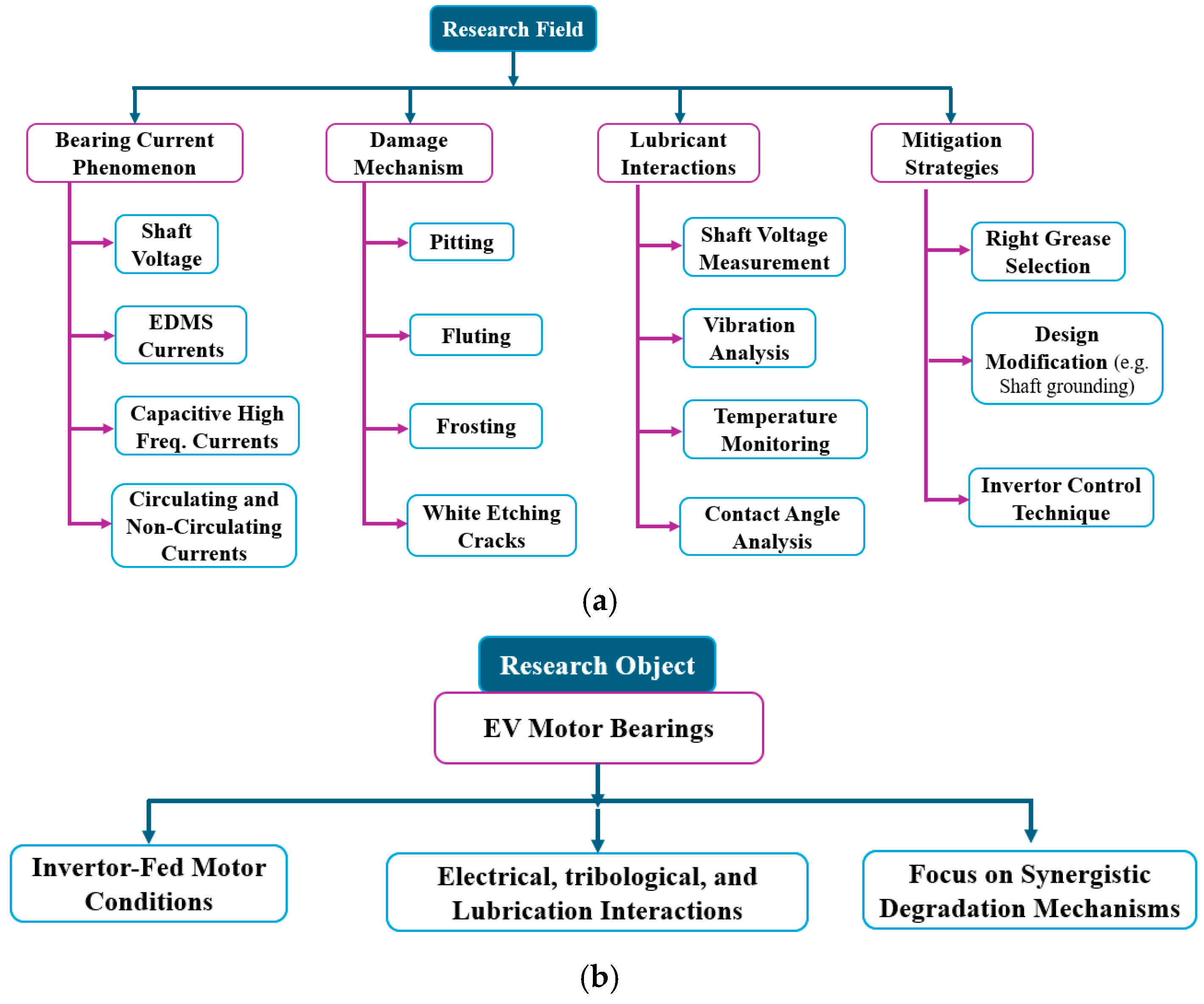
Figure 1. (a) Research field and (b) research object of the present work.
Lubricants 13 00349 g001
Figure 2. Equivalent high-frequency circuit model of an induction motor used for condition monitoring, illustrating capacitive paths and bearing current flow mechanisms.
Lubricants 13 00349 g002
Figure 3. Schematic representation of common bearing current circulation mechanisms in electric motors: (a) grounding through bearings resulting in current discharge to the motor frame, and (b) closed-loop circulating current traversing the stator, rotor, and bearings. These paths highlight potential damage zones critical to motor reliability and insulation integrity [51].
Lubricants 13 00349 g003
Figure 4. (a) Before and after conditions of lubricating gear oil exposed to harmful EDMS current [16] after EDMS and (b) pristine and failed grease after common mode voltage (CMV).
Lubricants 13 00349 g004
Figure 5. Classification of bearing currents based on their generation [64].
Lubricants 13 00349 g005
Figure 6. (a) Pitting on inner ring of bearing, (b) pitting on the bearing ball, and (c) magnified image of micro-pits near damaged area.
Lubricants 13 00349 g006
Figure 7. Frosting damage on the bearing surface: (a) pristine surface and (b) frosted damage.
Lubricants 13 00349 g007
Figure 8. (a) Fluting pattern on inner ring of bearing [79]. (b) Fluting on bearing ball [16].
Lubricants 13 00349 g008
Figure 9. (a) The inner ring of a cylindrical roller bearing. (b) The metallographic analysis post-etching reveals the presence of WECs [16].
Lubricants 13 00349 g009
Figure 10. Bearing lubricating grease changes at different voltages after 500 h of operation [87]. (a) Pristine, (b) at 12 V, and (c) at 13 V.
Lubricants 13 00349 g010
Figure 11. Important external points for system measure [18].
Lubricants 13 00349 g011
Table 1. Comparison of bearing current mitigation methods.
MethodCategoryFunctionalityAdvantagesLimitations
Insulated BearingsBreak Current PathInterrupts current path through high electrical resistanceSimple to implement, widely availableMay not prevent high-frequency discharge
Hybrid Ceramic BearingsBreak Current PathPrevents current flow due to insulating ceramic elementsHighly effective, durable under harsh conditionsHigher cost, complex manufacturing
Shaft Grounding BrushesBreak Current PathProvides a low-impedance path to groundCost-effective, easily retrofittedBrush wear and maintenance needed
Electrostatic ShieldingBreak Current PathBlocks electric fields along shaftMinimizes electrostatic chargingDesign complexity, less commonly applied
Common-Mode ChokeReduce SourceSuppresses high-frequency common-mode currentsReduces EMI, improves reliabilityAdded cost, may require tuning
dv/dt FilterReduce SourceLimits voltage slope (dv/dt) to reduce common-mode voltageProtects insulation systemVoltage drop, space requirement
Shielded CablesReduce SourcePrevents electromagnetic interference and leakage currentsReduces noise and leakage currentsMay not fully filter high-frequency harmonics
Sinusoidal FilterReduce SourceSmooths PWM waveform to reduce electrical noise and CMVImproves motor performance, extends bearing lifeBulkier, expensive for compact systems
Table 2. Comparison of key studies, emphasizing their focusing area, novelty, and limitations.
Ref No.Focus AreaContributionLimitation
[2]EV bearing current failuresComprehensive review of failure modesLimited discussion on lubricant degradation
[3]Discharge behavior in EV bearingsExperimental study on single-contact dischargesSpecific to single contact, not system-level
[4]Nano-lubricants for EVsReview of nano-lubricants potentialLimited focus on bearing currents
[6]Bearing current mechanismsDetailed mechanisms and mitigation techniquesMinimal lubricant-related discussion
[7]Bearing current damageMorphological damage review (frosting, fluting)Limited lubricant property analysis
[8]E-motor bearing dischargesExperimental + numerical approachFocused on electrical effects, less on tribology
[9]Tribology of EV driveline lubesTribological evaluation in electrified setupsLacks electrical discharge focus
[10]Shaft voltage effectsImpact on GCr15 bearing materialMaterial specific, not broad motor systems
[11]PWM drive and bearing currentsEarly study linking PWM to bearing currentsNo lubrication analysis
[16]Micro/nano damage, measurementMicrostructural damage from currentsLimited lubricant comparison
[18]Industrial motor mitigationMitigation techniques for shaft voltageGeneral motors, not EV-focused
[24]Non-conductive lube effect on bearingsDiscusses arcing from film breakdownNot experimental
[26]Speed/lube viscosity & pittingLinks speed, viscosity to pitting, flutingContext specific to EVs
[27]Bearing current variablesHighlights role of film thickness, impedanceTheoretical focus
[28]Shaft voltage sensitivitySensitivity to inverter/motor paramsLacks tribological/lubricant integration
[29]Nanoparticle grease in bearingsShows effectiveness on discharge damageFocused on two nanoparticle types
[30]Electrical pitting preventionPreventative device studyDevice-specific, not generalizable
[31]Tribological effects of damageTribology under electrical damageLacks lubricant chemistry evaluation
[56]Lube conductivity/bearing currentsExperimental lube conductivity resultsNo long-term lube stability analysis
[66]Conductive greasePrevent electrical pitting using greaseFocused on grease, not whole system
Disclaimer/Publisher’s Note: The statements, opinions and data contained in all publications are solely those of the individual author(s) and contributor(s) and not of MDPI and/or the editor(s). MDPI and/or the editor(s) disclaim responsibility for any injury to people or property resulting from any ideas, methods, instructions or products referred to in the content.