Static Characteristic Analysis of Multi-Layer Foil Thrust Bearing: Considering Parameter Effects


Abstract
1. Introduction
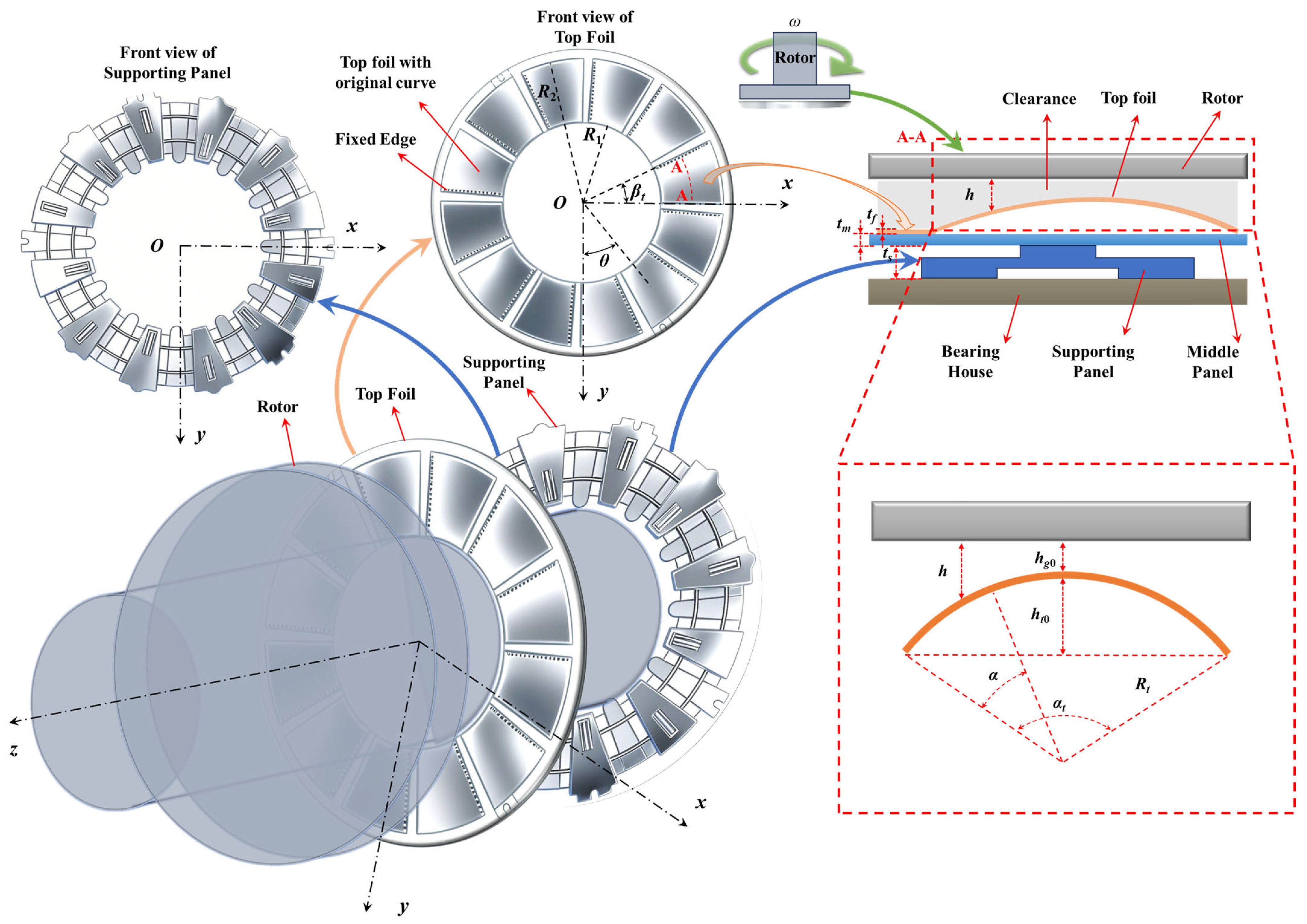
2. Numerical Models
2.1. Reynolds Equation
2.2. Gas Film Thickness Equation
2.3. Gas Film Thickness Equation at Tilted Thrust Disc
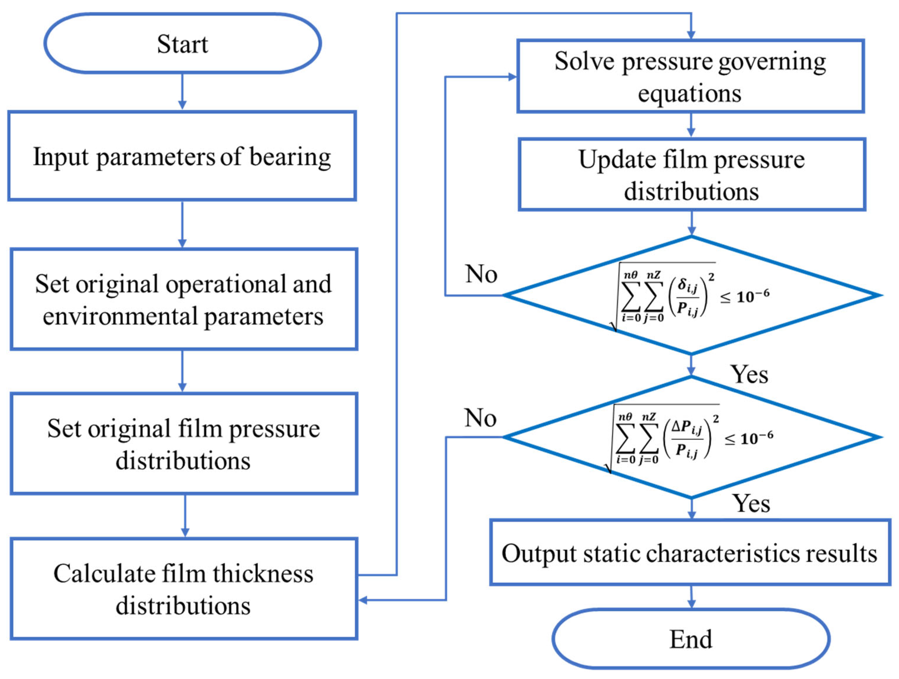
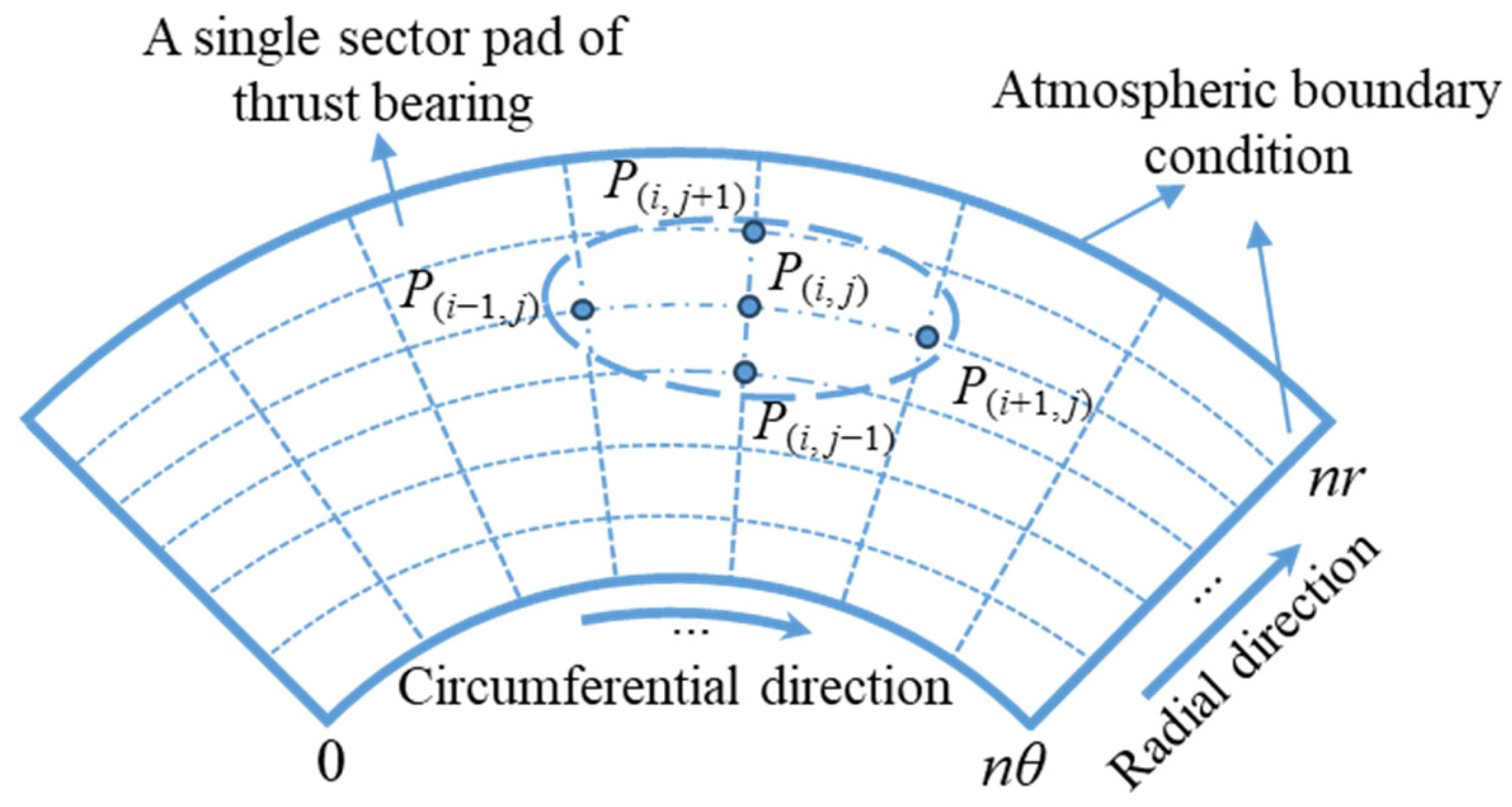
2.4. The Solution Processes of the Static Characteristics
2.5. Calculation Flow Chart of Static Characteristic
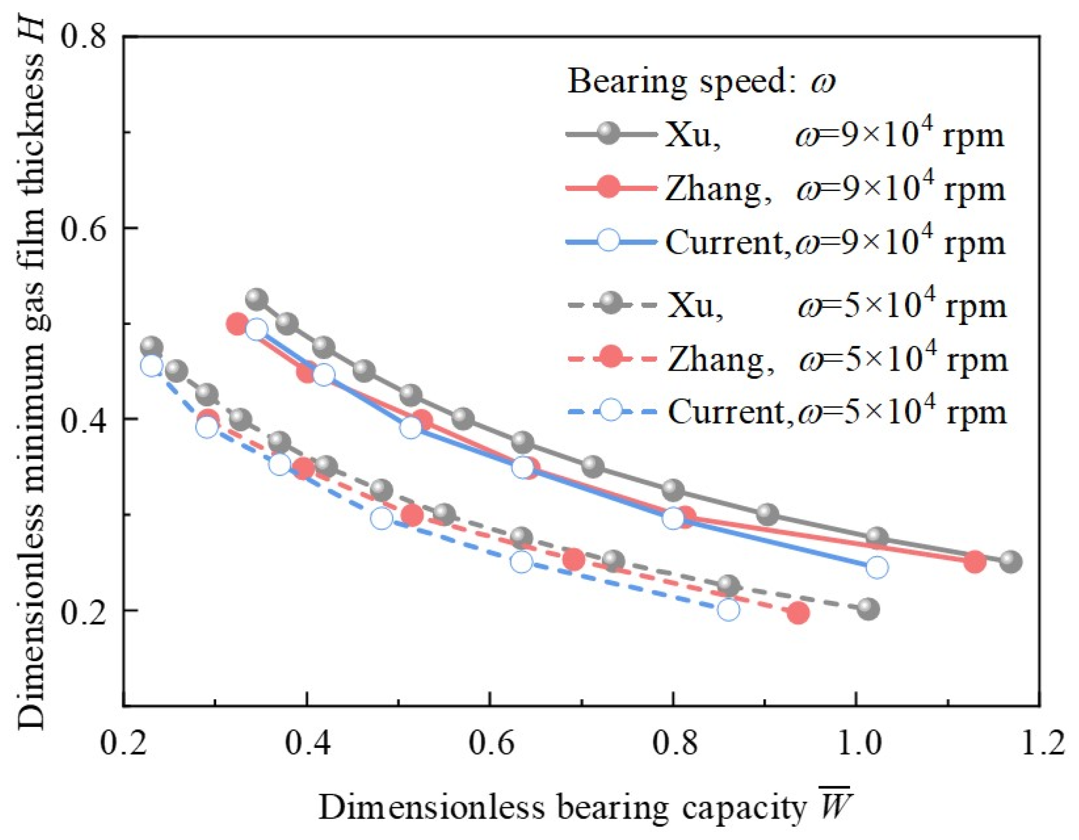
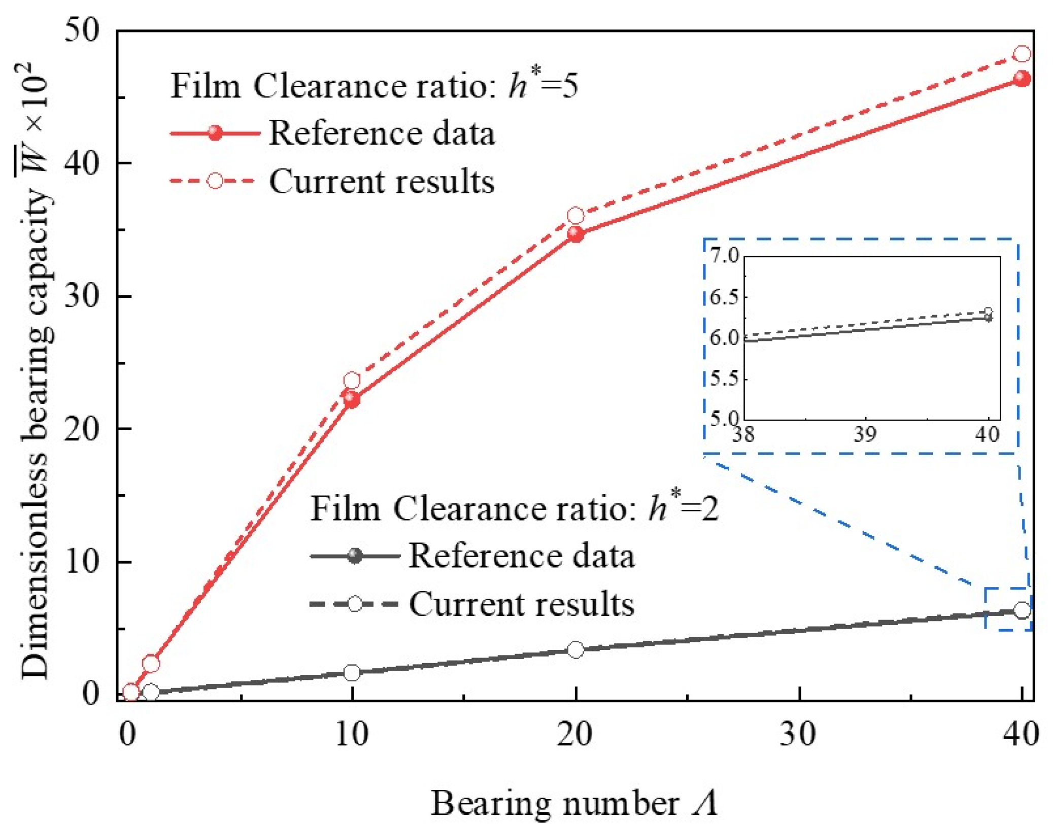
2.6. Validation of Model
3. Results and Discussion
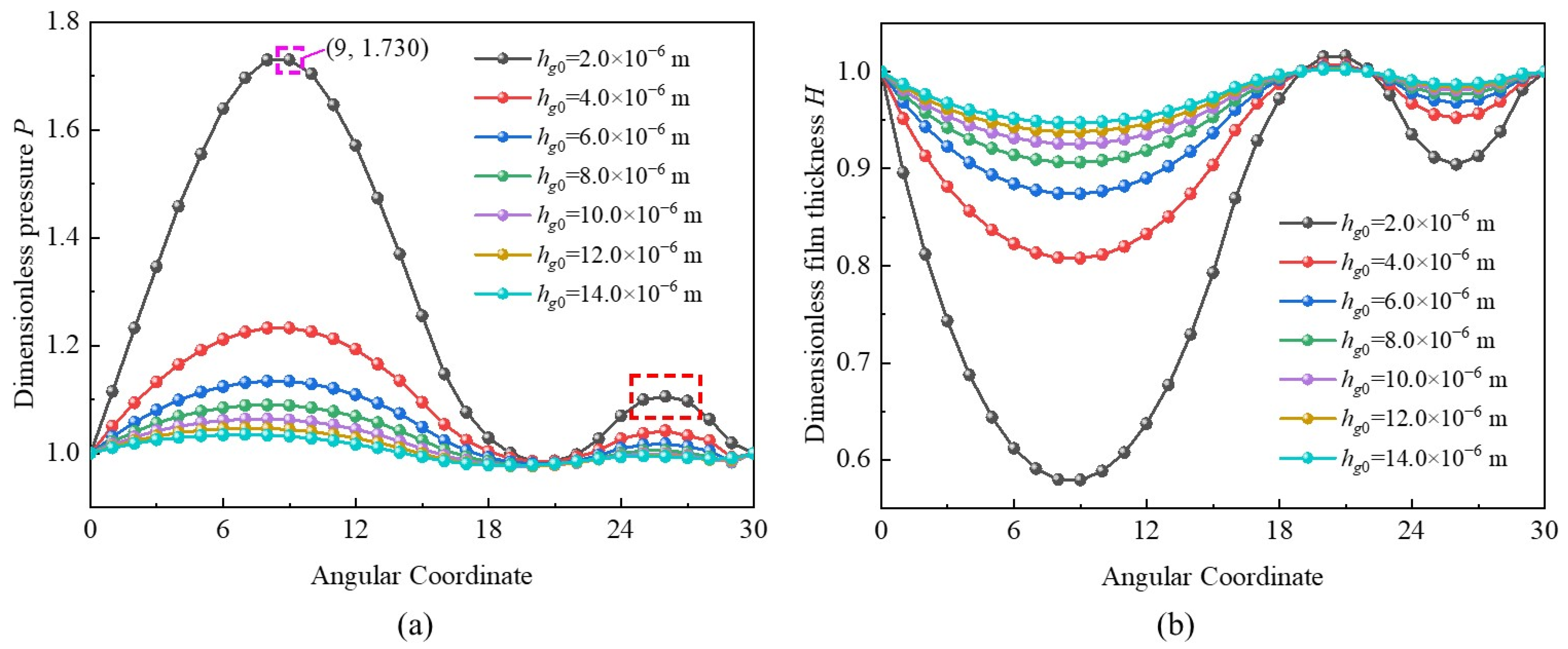
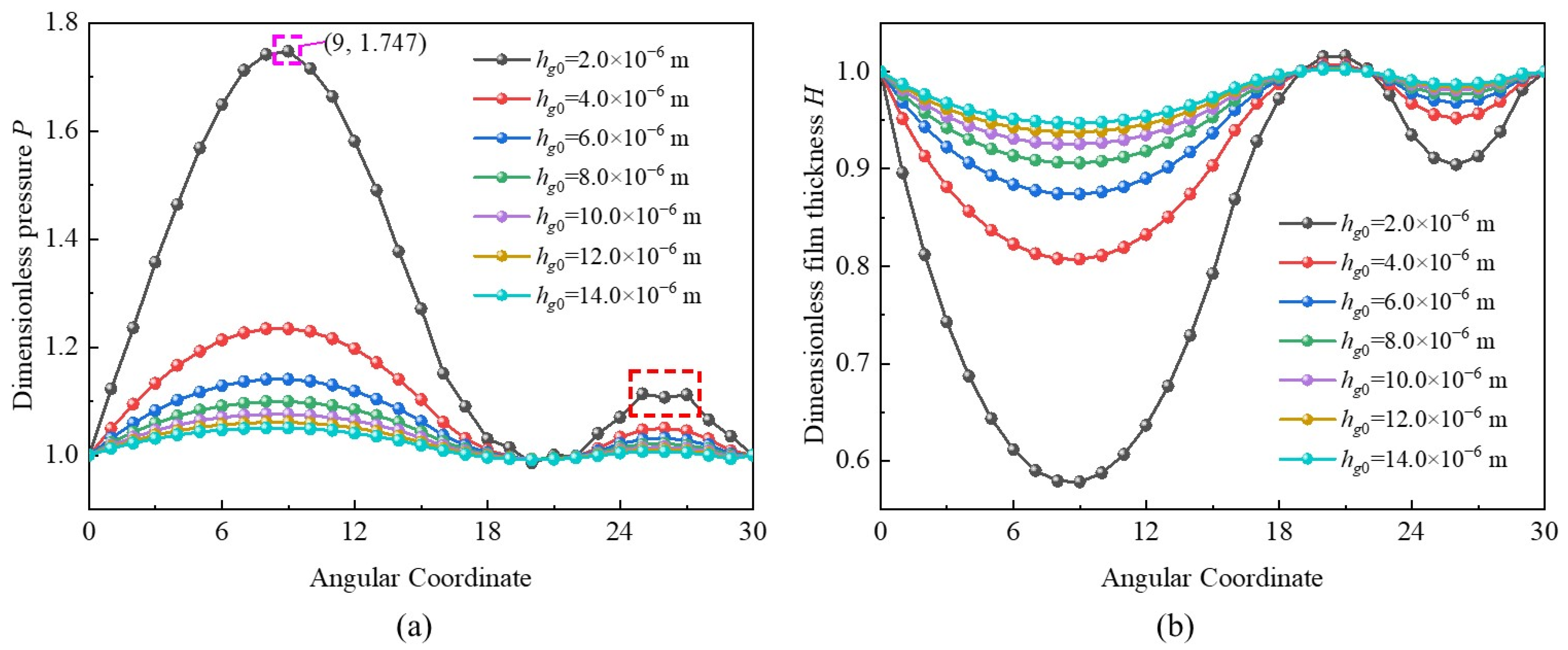
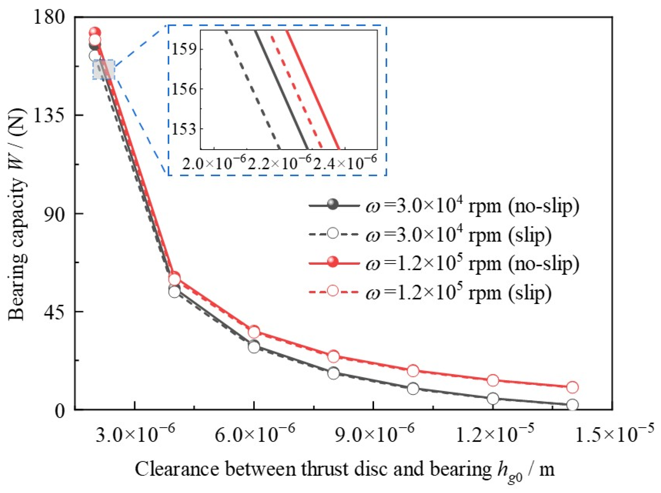
3.1. Effects of Clearance
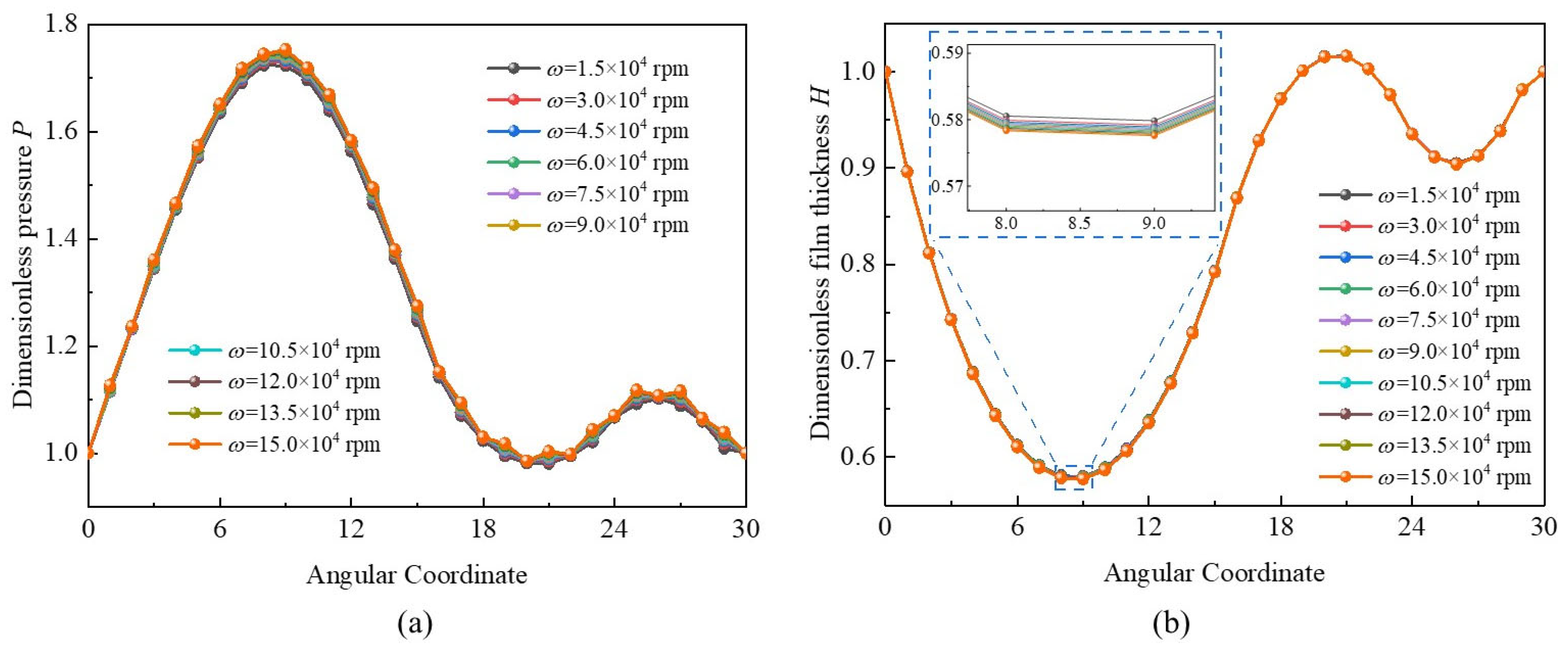
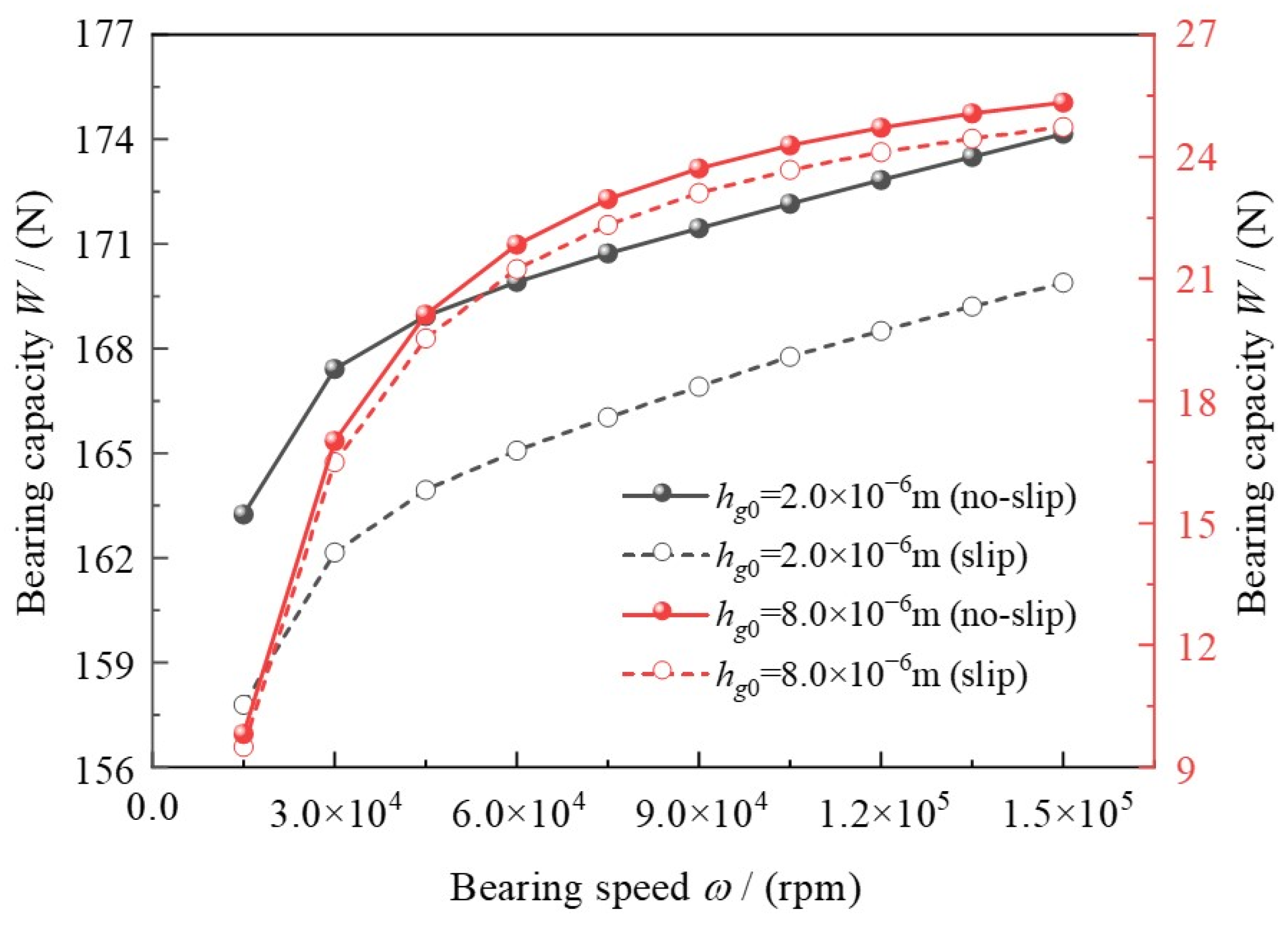
3.2. Effects of Bearing Speed
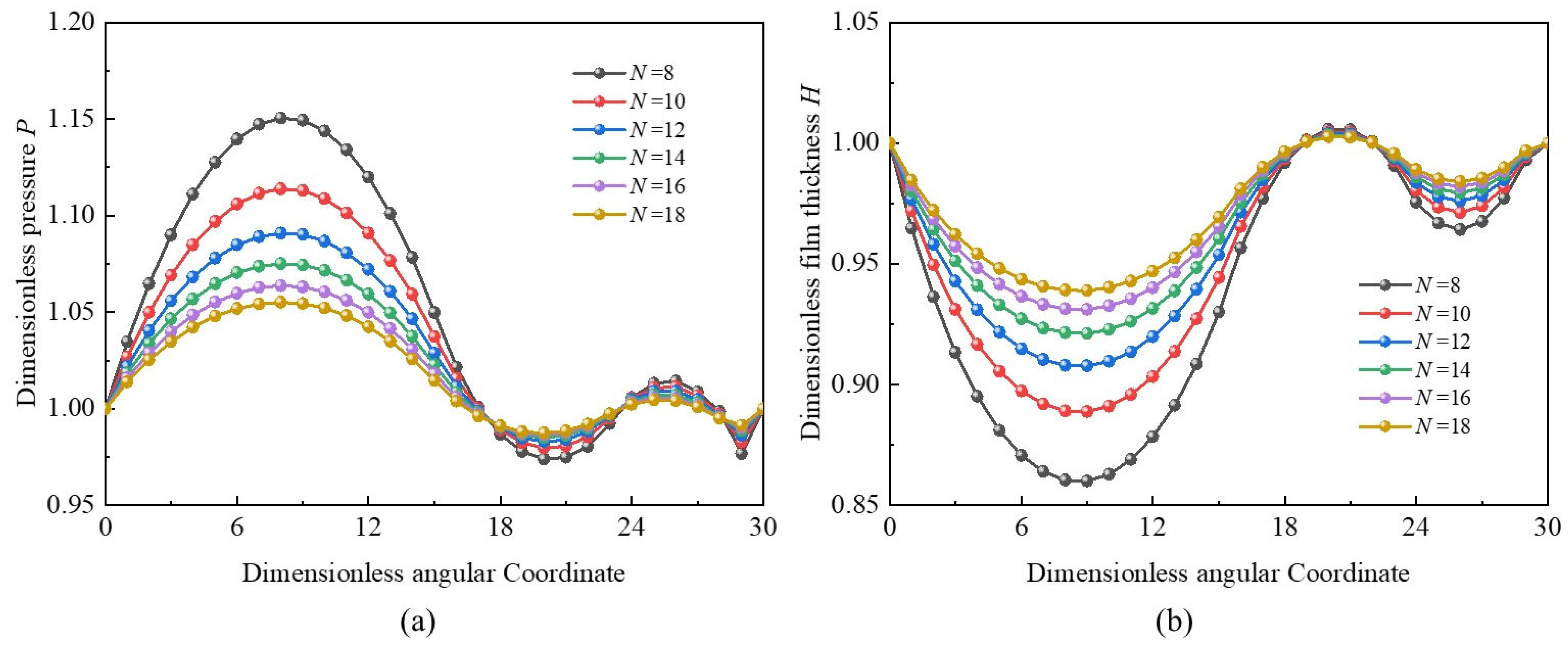
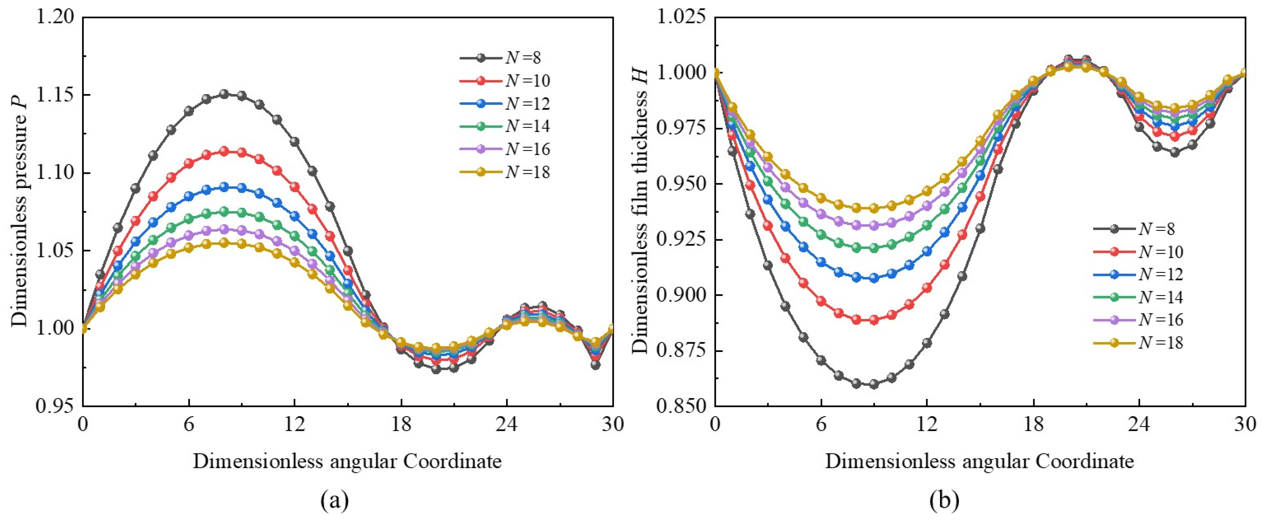
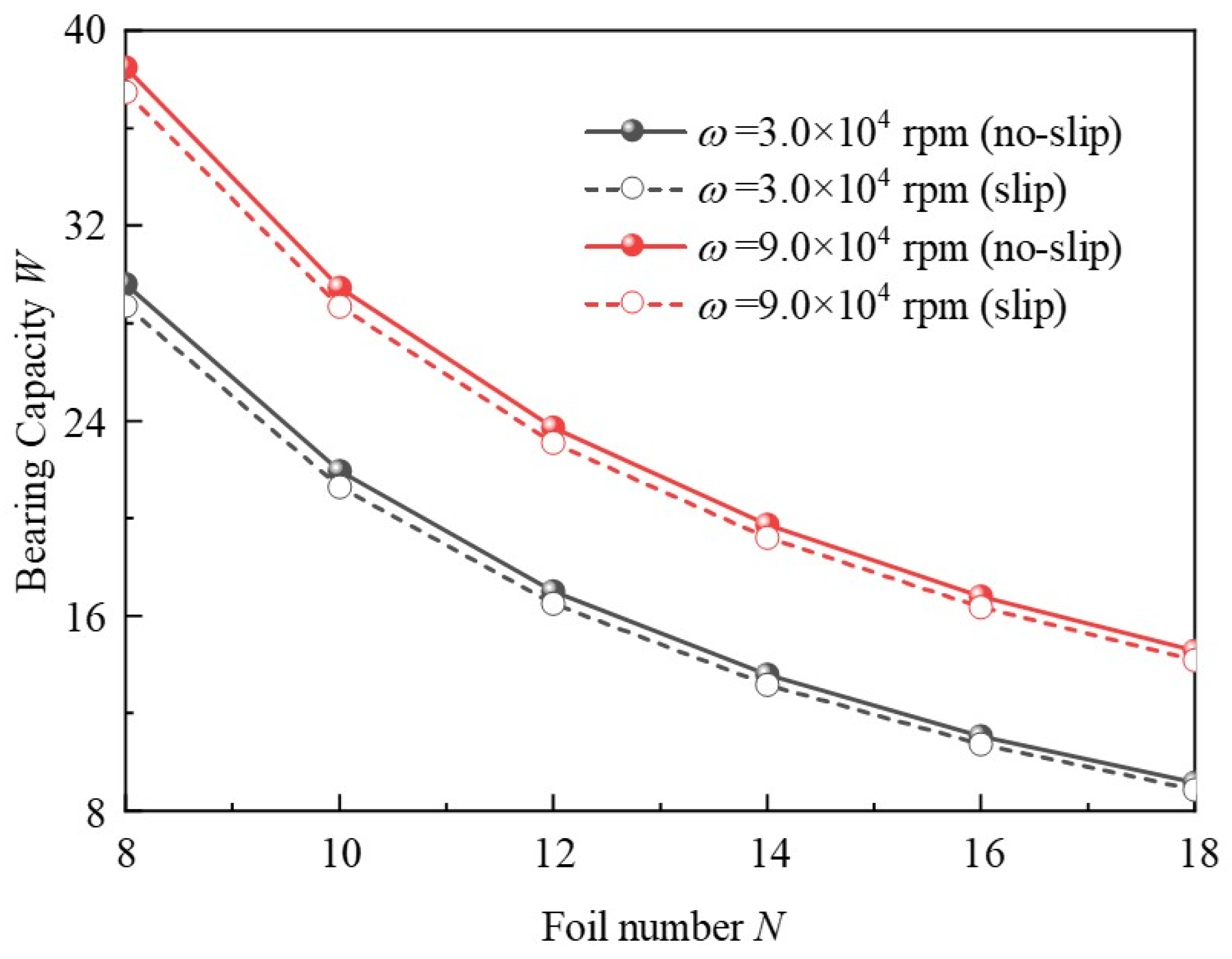
3.3. Effects of Foil Number
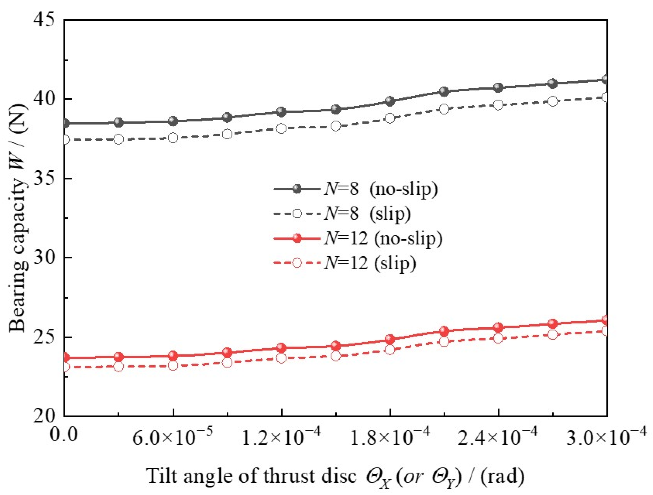
3.4. Effects of Tilt Angle
4. Conclusions
- (1)
- The numerical model reinforces the static characteristics analysis of the MLFTB. The parameter effects can be directly and efficiently acquired by numerical methods with high calculation accuracy.
- (2)
- The results indicate that bearing capacity could be generally decreased by around 3.15% when the slip boundary condition is considered, especially under small clearance and low bearing speed, which should not be neglected.
- (3)
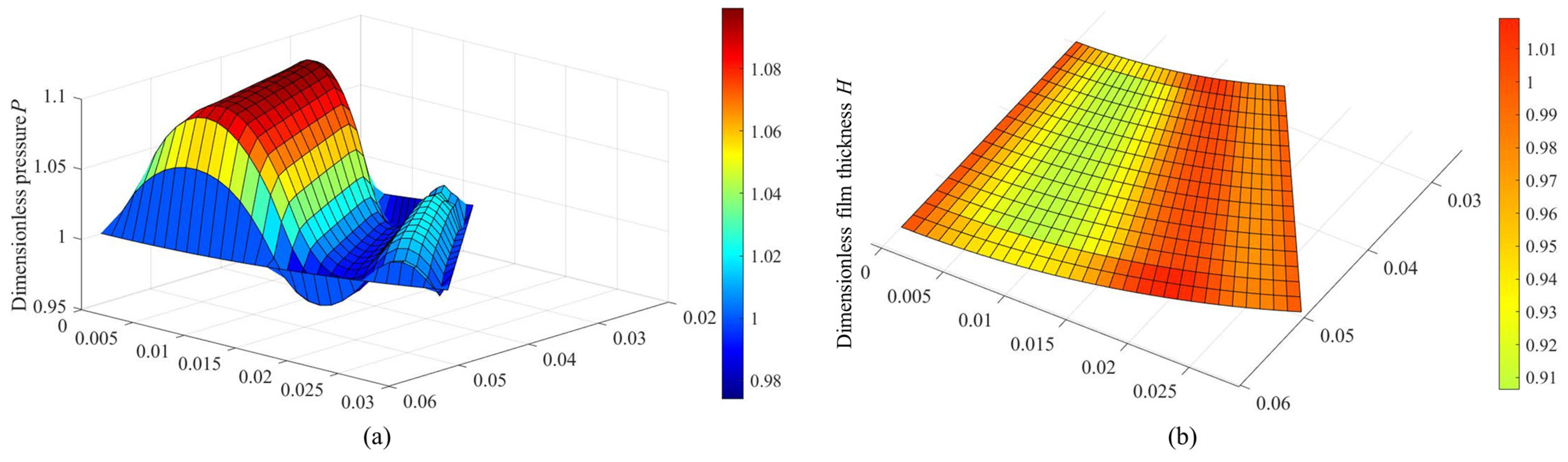
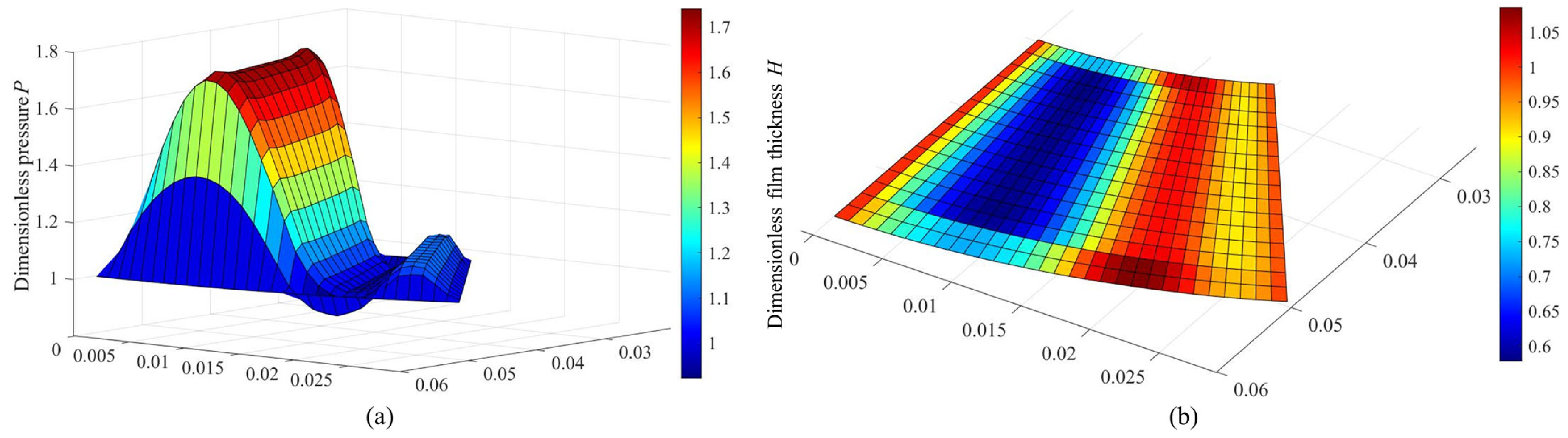
- The so-called “double wedge effect” characteristic of MLFTB with double-peak pressure and double-valley film thickness differs from the traditional foil thrust bearing with top and bump foils. However, it can disappear when hg0 > 12.0 × 10⁻⁶ m.The increase in tilt angle could result in a slight enhancement of bearing capacity, and the large foil number can slightly decrease the slip effect. The MLFTB exhibits good anti-tilting performance.
- (4)
- In summary, these findings concentrate on the influences of parameters on the static characteristics. Moreover, investigating the impact of aerodynamic heat performance may contribute to insights into MLFTB and lead to better properties.
Author Contributions
Funding
Data Availability Statement
Conflicts of Interest
Nomenclature
| Symbols | ts | Height of supporting panel, m | |
| a | Surface coefficient | W | Bearing capacity, N |
| Eb | Foil elastic modulus, Pa | wi | Lateral movement of each node |
| Fall | Gas film pressure vector on the surface of the top foil | Dimensionless bearing capacity | |
| fd | Disturbance frequency, Hz | u | Axial deformation of the foil |
| H | Dimensionless gas film thickness | uf | Radial deformation of the foil |
| H0 | Original film thickness, m | U | Dimensionless foil radial deformation |
| h | Average film thickness, m | Uall | Foil deformation |
| ht0 | Pitch of arch of the top foil at inner and outer radiuses, m | υb | Foil Poisson’s ratio |
| Kn | Knudsen number | ||
| N | Foil number | Greek | |
| O | Center | αt | Flare angle at inner and outer radius of a sector, rad |
| P | Dimensionless pressure | σv | Accommodation coefficient of tangential momentum |
| pa | Circumstance pressure, Pa | μ | Dynamic viscosity, Pa·s−1 |
| R | Bearing radius, m | θ | Circular angle coordinate, rad |
| Rg | Gas constant | θri | Lateral movement wi of each node |
| Ri | Inner (when i = 1) and outer (when i = 2) radiuses, m | Λ | Bearing number |
| Rt | Radius of top foil, m | ω | Bearing speed, rpm |
| T0 | Reference temperature, K | βt | Flare angle of the sector of bearing bush, rad |
| tf | Thickness of top foil, m | ωs | Oscillation frequency, rad·s−1 |
| tm | Thickness of middle panel, m | γ | Vortex frequency |
| Subscripts | |||
| f | Foil | t | Top foil |
| m | Middle panel | s | Supporting panel |
| g | Gas | 0 | Original |
References
- Andres, L.S.; Rodriguez, B. Experiments with a rotor-hybrid gas bearing system under going maneuver loads from its base support. J. Eng. Gas Turb. Power 2020, 142, 111004. [Google Scholar] [CrossRef]
- Jiang, Y.; Zhu, Q.; Xu, B.; Huang, Z.; Gao, D. The Influences of Parameters on the Dynamic Characteristics of a Multi-Foil Aerodynamic Journal Bearing with Bump-Backing Foils: Model Predictions. Lubricants 2024, 12, 386. [Google Scholar] [CrossRef]
- Gao, Q.H.; Sun, W.J.; Zhang, J.Z. A comparative study on inflow schemes of radial throughflow cooling for thermal management of a specific multi-layer gas foil thrust bearing. Int. J. Heat Mass Tran. 2023, 216, 124564. [Google Scholar] [CrossRef]
- Andres, L.S. A Review of Turbine and Compressor Aerodynamic Forces in Turbomachinery. Lubricants 2023, 11, 26. [Google Scholar] [CrossRef]
- Zhang, B.; Qi, S.M.; Feng, S. An experimental investigation of a microturbine simulated rotor supported on multileaf gas foil bearings with backing bump foils. Proc. Inst. Mech. Eng. Part J. J. Eng. Tribol. 2018, 232, 1169–1180. [Google Scholar] [CrossRef]
- Samanta, P.; Murmu, N.C.; Khonsari, M.M. The evolution of foil bearing technology. Tribol. Int. 2019, 135, 305–323. [Google Scholar] [CrossRef]
- Sim, K.; Lee, Y.B.; Kim, T.H. Effects of mechanical preload and bearing clearance on rotordynamic performance of lobed gas foil bearings for oil free turbochargers. Tribol. Trans. 2013, 56, 224–235. [Google Scholar] [CrossRef]
- Hou, Y.; Zhao, Q.; Guo, Y.; Ren, X.; Lai, T.; Chen, S. Application of gas foil bearings in China. Appl. Sci. 2021, 11, 6210. [Google Scholar] [CrossRef]
- Li, Y.Y.; Lei, G.; Sun, Y. Effect of environmental pressure enhanced by a booster on the load capacity of the aerodynamic gas bearing of a turbo expander. Tribol. Int. 2017, 105, 77–84. [Google Scholar] [CrossRef]
- Dellacorte, C. Oil-Free shaft support system rotordynamics: Past, present and future challenges and opportunities. Mech. Syst. Signal Pract. 2012, 29, 67–76. [Google Scholar] [CrossRef]
- Zhao, Q.; Yan, S.H.; Qiang, M.C.; Hou, Y.; Lai, T.W. Thermal analysis and optimization of bionic cooling channels of gas foil thrust bearings. Proc. IME J. J. Eng. Tribol. 2024, 238, 193–210. [Google Scholar] [CrossRef]
- Lehn, A.; Mahner, M.; Schweizer, B. A contribution to the thermal modeling of bump type air foil bearings: Analysis of the thermal resistance of bump foils. J. Tribol. 2017, 139, 061702. [Google Scholar] [CrossRef]
- Kumar, J.; Khamari, D.S.; Behera, S.K.; Sahoo, R.K. Influence of slip-flow phenomenon on thermohydrodynamic behaviour of gas foil thrust bearings. Proc. IME J. J. Eng. Tribol. 2022, 236, 15–30. [Google Scholar] [CrossRef]
- Lai, T.W.; Guo, Y.; Wang, W.; Wang, Y.; Hou, Y. Development and application of integrated aerodynamic protuberant foil journal and thrust bearing in turboexpander. Int. J. Rotating Mach. 2017, 1, 8430943. [Google Scholar] [CrossRef]
- Shi, T.; Huang, H.Y.; Chen, Q.L.; Peng, X.Y.; Feng, J.M. Performance investigation and feasibility study of novel gas foil thrust bearing for hydrogen fuel cell vehicles. Int. J. Energ. Res. 2022, 46, 12642–12659. [Google Scholar] [CrossRef]
- Zhang, C.B.; Ao, H.R.; Jiang, H.Y.; Zhou, N.N. Investigations on start-up performances of novel hybrid metal rubber-bump foil bearings. Tribol. Int. 2021, 154, 106751. [Google Scholar] [CrossRef]
- Zhang, G.H.; Huang, M.; Cheng, G.L.; Li, J.S.; Liu, Y.; He, J.G.; Zheng, Y.Q.; Tang, S.W.; Cui, H.L. Design and optimization of fluid lubricated bearings operated with extreme working performances—A comprehensive review. Int. J. Extrem. Manuf. 2024, 6, 022010. [Google Scholar] [CrossRef]
- Jiang, Y.L.; Xu, B.; Lu, X.; Liu, D. Multiscale simulation of flow in gas-lubricated journal bearings: A comparative study between the Reynolds equation and lattice Boltzmann methods. Eng. Appl. Comp. Fluid 2021, 15, 1792–1810. [Google Scholar] [CrossRef]
- LaTray, N.; Kim, D. Design of novel gas foil thrust bearings and test validation in a high-speed test rig. J. Tribol. 2020, 142, 071803. [Google Scholar] [CrossRef]
- Li, H.; Geng, H.; Qi, L.; Gan, L. Effects of wedge curvature on performances of foil thrust bearing and the profile design in compressor system. Proc. IME J. J. Eng. Tribol. 2021, 235, 1868–1878. [Google Scholar] [CrossRef]
- Hu, H.Y.; Feng, M. Influence of wedge shape on the performance of air foil thrust bearings. Ind. Lubr. Tribol. 2019, 73, 23–32. [Google Scholar] [CrossRef]
- Kim, T.H.; Park, M.; Lee, T.W. Design optimization of gas foil thrust bearings for maximum load capacity. J Tribol. 2017, 139, 031705. [Google Scholar] [CrossRef]
- Xu, F.; Dong, Z.; Chu, J.; Wang, H.; Wang, Y. Experimental analysis of influence of double-layer bump foils on aerodynamic thrust foil bearings performance. Ind. Lubr. Tribol. 2022, 74, 127–133. [Google Scholar] [CrossRef]
- Guo, Y.; Hou, Y.; Zhao, Q.; Ren, X.; Chen, S.; Lai, T. Numerical and experimental studies on the thermal and static characteristics of multi-leaf foil thrust bearing. Proc. IME J. J. Eng. Tribol. 2022, 236, 405–420. [Google Scholar] [CrossRef]
- Gao, Q.H.; Sun, W.J.; Zhang, J.Z.; Li, J.Z.; Zhang, J.Y. Thermo-elasto-hydrodynamic analysis of gas foil bearing considering thermal effects. Int. J. Mech. Sci. 2025, 288, 110008. [Google Scholar] [CrossRef]
- Gao, Q.H.; Sun, W.J.; Zhang, J.Z.; Li, J.Z.; Zhang, J.Y. Thermo-elasto-hydrodynamic analysis of a specific multi-layer gas foil thrust bearing under thermal-fluid–solid coupling. Chin. J. Aeronaut. 2023, 36, 231–246. [Google Scholar] [CrossRef]
- Jiang, Y.; Xu, B.; Zhu, Q.; Huang, Z.; Gao, D. Parameter Effects on the Static Characteristics of the Multi-Foil Aerodynamic Journal Bearing with Bump-Backing Foils. Lubricants 2024, 12, 246. [Google Scholar] [CrossRef]
- Iordanoff, I. Analysis of an aerodynamic compliant foil thrust bearing: Method for a rapid design. J. Tribol.-Trans. ASME 1999, 121, 816–822. [Google Scholar] [CrossRef]
- Hou, A.P.; Lin, P.C.; Wang, R.; Li, J.X.; Hu, B. Performance of air-dynamic lubrication thrust bearing and experiment. J. Aerosp. Power 2018, 33, 1510–1518. [Google Scholar]
- Larsen, J.S.; Santos, I.F.; Osmanski, S.V. Stability of rigid rotors supported by air foil bearings: Comparison of two fundamental approaches. J. Sound Vib. 2016, 381, 179–191. [Google Scholar] [CrossRef]
- Lehn, A.; Mahner, M.; Schweizer, B. Characterization of static air foil thrust bearing performance: An elasto-gasdynamic analysis for aligned, distorted and misaligned operating conditions. Arch. App. Mech. 2018, 88, 705–728. [Google Scholar] [CrossRef]
- Hu, Y.; Ding, P.; Wu, F.; Wang, X.; Liang, B.; Meng, Y. Theoretical and experimental research on static stiffness, performance, and lift-off characteristics of multi-layer gas foil thrust bearings. Friction 2024, 12, 2458–2479. [Google Scholar] [CrossRef]
- Zhang, J.Y.; Meng, G.R.; Chen, B.X.; Lv, Y.W.; Zhang, J.Z.; Luo, X.Y. Loading capacity of multi-layer foil gas thrust bearing. J. Aerosp. Power 2023, 38, 1423–1431. [Google Scholar]
- Xu, K.F.; Zhang, G.H.; Han, J.Z.; Huang, Z.W.; Ji, S.W. Simulation and experimental study on static characteristics of multi-layer thrust foil bearing. J. Aerosp. Power 2024, 39, 20220672. [Google Scholar]
- Kango, S.; Shukla, D.K.; Sharma, N.; Arif, M. Implication of surface texture and slip on hydrodynamic fluid film bearings: A comprehensive survey. Tribol. Online 2020, 15, 265–282. [Google Scholar]
- Bruckner, R.J.; DellaCorte, C.; Prahl, J.M. Analytic Modeling of the Hydrodynamic, Thermal, and Structural Behavior of Foil Thrust Bearings; Report No. TM-213811; NASA: Pasadena, CA, USA, 2005. [Google Scholar]
- Park, D.J.; Kim, C.H.; Jang, G.H.; Lee, Y.B. Theoretical considerations of static and dynamic characteristics of air foil thrust bearing with tilt and slip flow. Tribol Int. 2008, 41, 282–295. [Google Scholar] [CrossRef]
- Jiang, Y.L.; Xu, B.; Xiong, C.; Lu, X.; Yu, H.; Chen, Z. Influence of slip effect on viscous dissipation heat and lubrication characteristics of gas journal bearing: A multiscale analysis. Numer. Heat Transf. Part A-Appl. 2023, 83, 1285–1302. [Google Scholar] [CrossRef]
- Radil, K.; Howard, S.; Dykas, B. The role of radial clearance on the performance of foil air bearings. Tribol. Trans. 2002, 45, 485–490. [Google Scholar] [CrossRef]
- Dykas, B. Factors Influencing the Performance of Foil Gas Thrust Bearings for Oil-Free Turbomachinery Applications. Ph.D. Thesis, Case Western Reserve University, Cleveland, OH, USA, 2006. [Google Scholar]
- Petyt, M. Introduction to Finite Element Vibration Analysis, 2nd ed.; Cambridge University Press: Cambridge, UK, 2010. [Google Scholar]
- Pilkey, W.D. Formulas for Stress, Strain, and Structural Matrices; John Wiley and Sons Incorporation: Hoboken, NJ, USA, 1994; pp. 878–879. [Google Scholar]
- Wang, N.Z.; Chang, C. An application of Newton’s method to the lubrication analysis of air-lubricated bearings. Tribol. Trans. 1999, 42, 419–424. [Google Scholar] [CrossRef]
- Heshmat, H.; Walowit, J.A.; Pinkus, O. Analysis of gas-lubricated foil journal bearings. J. Lubr. Technol.-Trans. ASME 1983, 105, 647–655. [Google Scholar] [CrossRef]
- Nan, G.D. Research on Static and Thermal Charactertics of Bump Foil Gas Thrust Bearing. Master’s Dissertation, Harbin Institute of Technology, Harbin, China, 2020. [Google Scholar]


| Parameter Name | Value |
|---|---|
| Outer radius of top foil (R2) | 57.15 × 10⁻³ m |
| Inner radius of top foil (R1) | 29.75 × 10⁻³ m |
| Thickness of top foil (tf) | 2.0 × 10⁻⁴ m |
| Thickness of middle panel (tm) | 1.1 × 10⁻⁴ m |
| Thickness of supporting panel (ts) | 8.2 × 10⁻⁴ m |
| Foil elastic modulus (Eb) | 2.2 × 10¹¹ Pa |
| Foil number (N) | 8~16 |
| Ambient pressure (pa) | 1.01325 × 10⁵ Pa |
| Foil Poisson’s ratio (υb) | 0.3 |
| Bearing speed (ω) | 3.0 × 10⁴~1.2 × 10⁴ rpm |
| Clearance between thrust disc and bearing (hg0) | 6.0 × 10⁻⁶ m~14.0 × 10⁻⁶ m |
| Dynamic viscosity of gas (μ) | 1.932 × 10⁻⁵ Pa·s |
Disclaimer/Publisher’s Note: The statements, opinions and data contained in all publications are solely those of the individual author(s) and contributor(s) and not of MDPI and/or the editor(s). MDPI and/or the editor(s) disclaim responsibility for any injury to people or property resulting from any ideas, methods, instructions or products referred to in the content. |
© 2025 by the authors. Licensee MDPI, Basel, Switzerland. This article is an open access article distributed under the terms and conditions of the Creative Commons Attribution (CC BY) license (https://creativecommons.org/licenses/by/4.0/).
Share and Cite
Jiang, Y.; Zhu, Q.; Huang, Z.; Gao, D. Static Characteristic Analysis of Multi-Layer Foil Thrust Bearing: Considering Parameter Effects. Lubricants 2025, 13, 285. https://doi.org/10.3390/lubricants13070285
Jiang Y, Zhu Q, Huang Z, Gao D. Static Characteristic Analysis of Multi-Layer Foil Thrust Bearing: Considering Parameter Effects. Lubricants. 2025; 13(7):285. https://doi.org/10.3390/lubricants13070285
Chicago/Turabian StyleJiang, Yulong, Qianjing Zhu, Zhongwen Huang, and Dongyan Gao. 2025. "Static Characteristic Analysis of Multi-Layer Foil Thrust Bearing: Considering Parameter Effects" Lubricants 13, no. 7: 285. https://doi.org/10.3390/lubricants13070285
APA StyleJiang, Y., Zhu, Q., Huang, Z., & Gao, D. (2025). Static Characteristic Analysis of Multi-Layer Foil Thrust Bearing: Considering Parameter Effects. Lubricants, 13(7), 285. https://doi.org/10.3390/lubricants13070285