3.1. Rigid–Flexible Coupling Dynamics Simulation Model
This study focuses on angular contact ball bearings with two-piece inner rings, which are utilized in aero-engine main shafts. The geometric parameters of a bearing are presented in
Table 1. Based on the interaction force model between bearing components described in
Section 2, a user subroutine was written in FORTRAN language to calculate the interaction forces between bearing components. The user subroutine was compiled and a dynamic link library (DLL) file was generated, which was then linked with the ADAMS solver module. Furthermore, secondary development of ADAMS was carried out using the CMD commands in the ADAMS system to develop a parameterized rigid–flexible coupling multi-body dynamics simulation analysis module for bearings in order to simulate and solve the rigid–flexible coupling dynamics model of the angular contact ball bearing with a two-piece inner ring. Different lubricant properties can be specified in the parameterized interface of the dynamics simulation analysis module as needed. Additionally, the dynamic simulation analysis module can be configured as needed to have the outer ring fixed with the inner ring rotating or the inner ring fixed with the outer ring rotating.
The construction and solution process of the rigid–flexible coupling dynamics model is illustrated in
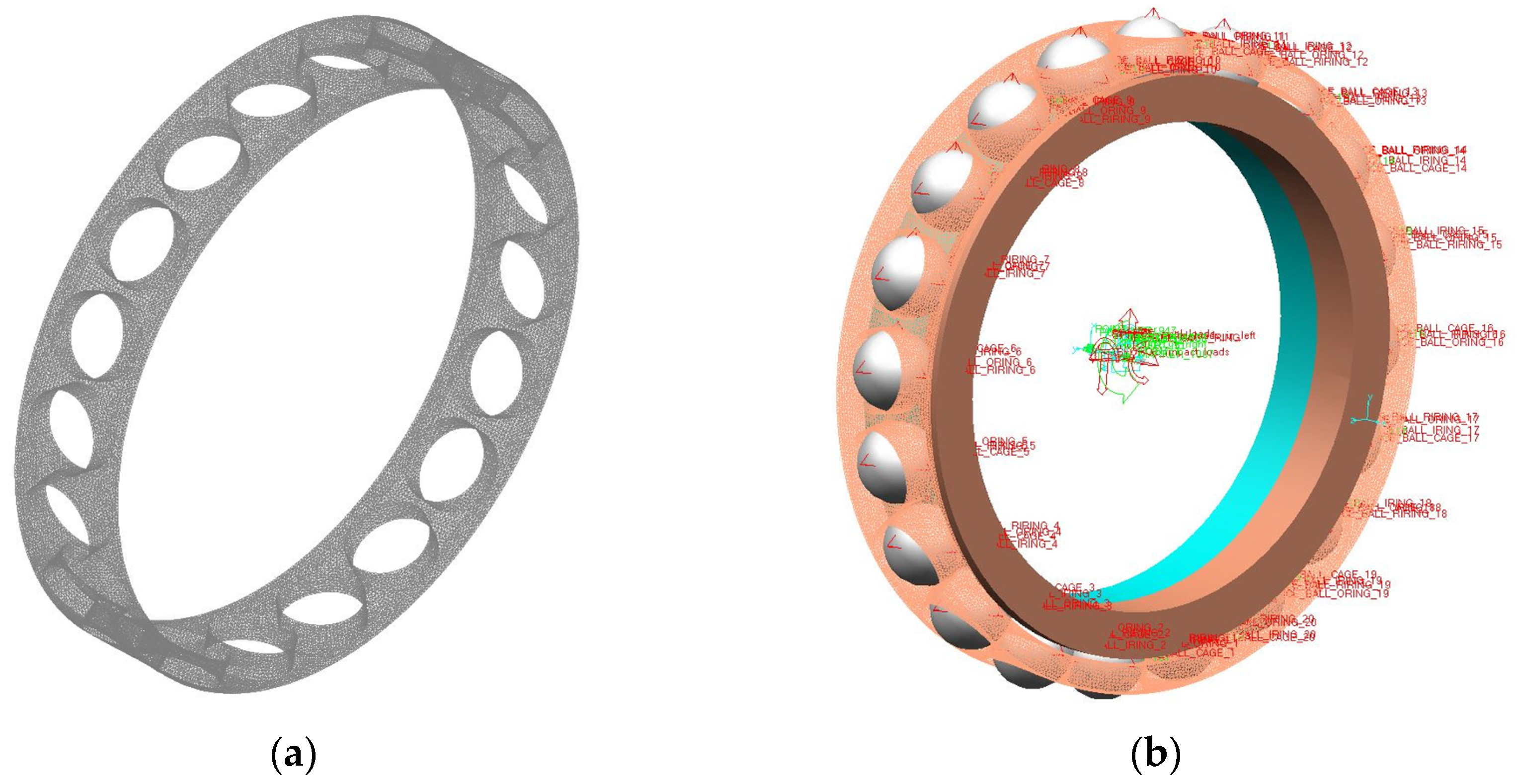
Figure 8. Based on considering the interaction relationships among bearing components, the bearing geometric parameters are input into the dynamic simulation analysis software ADAMS (2019 version). A rigid-body dynamic model is constructed through the developed parameterized rigid–flexible coupling dynamic simulation analysis module. The rigid cage is imported into the finite element analysis software ABAQUS (2024 version) for flexible treatment, and then the generated MNF file of the flexible cage is imported into the dynamic simulation analysis software ADAMS. The MNF, which stands for Modal Neutral File, acts as an interface file between finite element software ABAQUS and the multi-body dynamics software ADAMS and is utilized to export the modal information of the flexible cage—including its nodes, elements, mass matrix, stiffness matrix, and modal shapes—after the flexibility treatment. This process allows for the incorporation of the elastic deformation effects of the cage in multi-body dynamics simulations. In the parametric rigid–flexible coupling dynamics simulation analysis module, the flexible cage replaces the rigid cage in the rigid-body dynamics model, and the connection between the flexible cage and other components is established through dummy bodies. Constraint forces are established among bearing components to construct the rigid–flexible coupling dynamics model. Input simulation parameters such as operating condition parameters including load, impact load and acceleration and deceleration conditions, material parameters of bearing components, and lubricant parameters for simulation analysis. In the solving process, the FORTRAN user subroutine reads the system state values at the beginning of each time step in ADAMS by calling the function subroutine SYSARY, calculates the force terms of the dynamic differential equations, and then passes them to the ADAMS solver through the array RESULT, completing the integration solution of the dynamic differential equations for each time step. In
Figure 9, the left figure depicts the flexible cage, while the right figure depicts the rigid–flexible coupled dynamic simulation model.
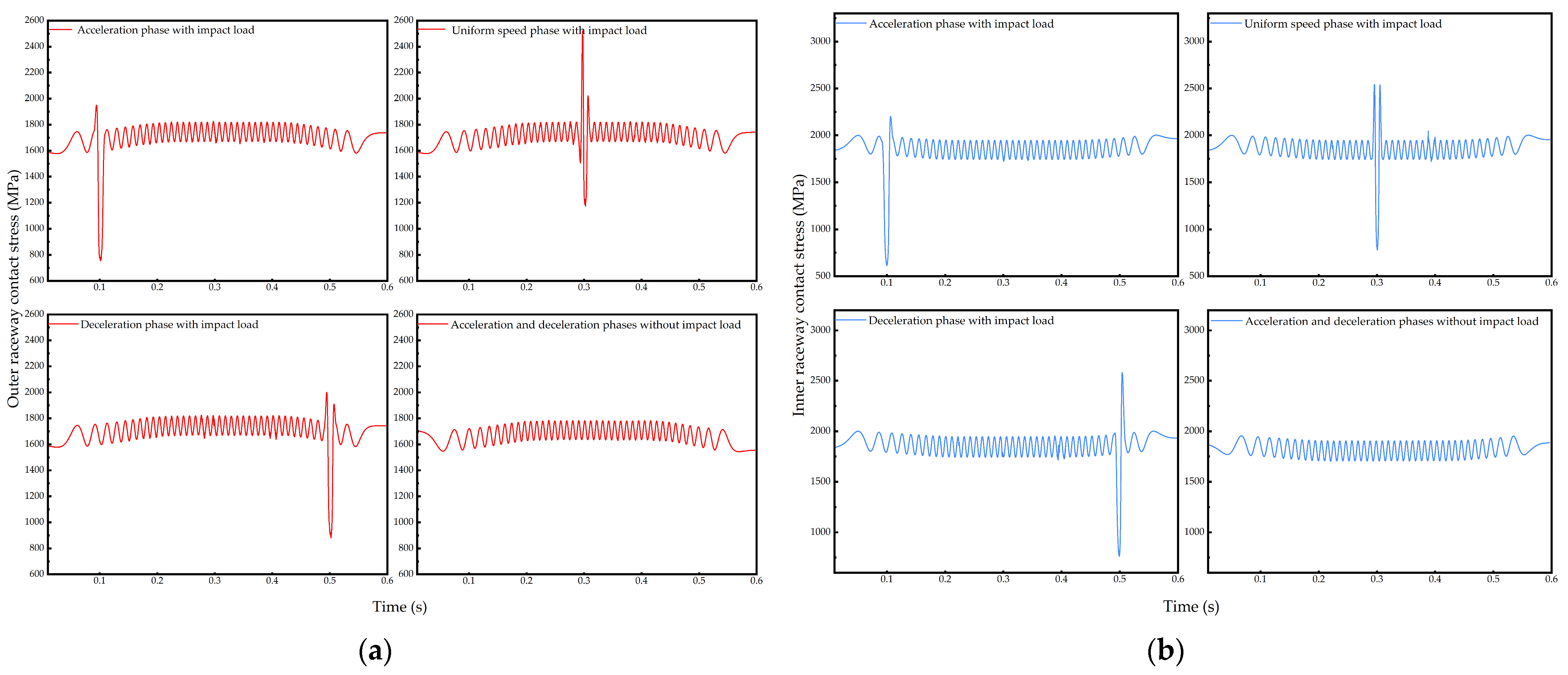
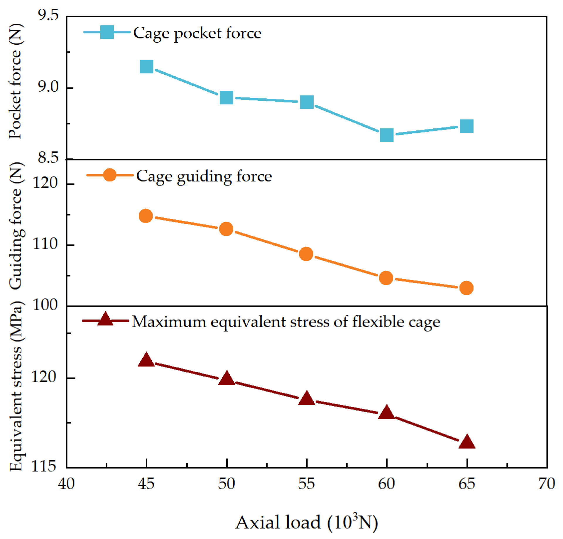
Utilizing the dynamic simulation analysis program, a simulation analysis of the dynamic model was conducted to obtain the interaction and motion states among the various components of a bearing. This includes parameters such as the contact stress between the balls and the inner and outer raceways, the collision force between the balls and the cage, the guiding force between the cage and the ring, the maximum equivalent stress of a flexible cage, and the cage slip rate. Additionally, the lubrication condition of the bearing can be assessed at any moment, including the thickness of the bearing oil film.
3.2. Test Verification
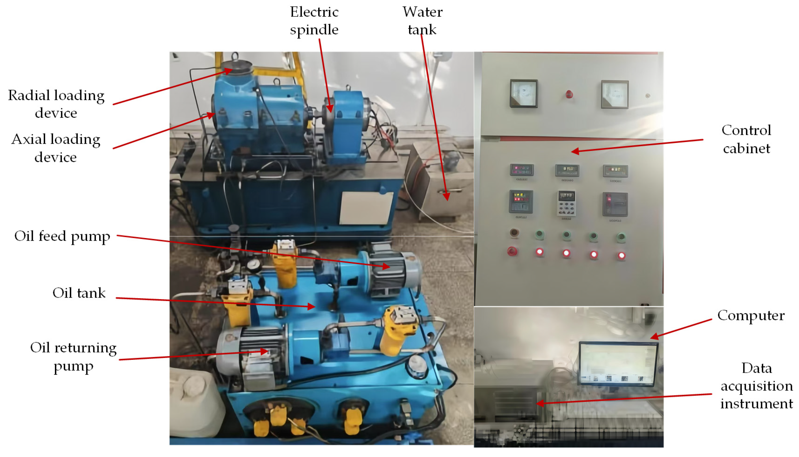
To verify the accuracy of the dynamic simulation model for bearing rigid–flexible coupling established, a cage slip rate test was executed on an angular contact ball bearing with a two-piece inner ring. The bearing test was performed using a dynamic performance test machine designed for an aero-engine main shaft bearing cage. The overall performance indicators of the test device are presented in
Table 2. The main components of the test apparatus are illustrated in
Figure 10, which primarily include an axial loading device, a radial loading device, an oil tank, an oil fuel pump, an oil return pump, an electric spindle, a water tank, a control cabinet, a data acquisition instrument, and a computer.
The test bearing was subjected to both radial and axial test loads via hydraulic loading, with the load magnitude controlled by a proportional pressure-reducing valve. The motor is coupled to the test spindle, ensuring accurate test loading while preventing any additional loads on the motor end. The test machine features both high-temperature and room-temperature lubrication systems. The high-temperature system supplies oil to the test bearing, with a maximum oil supply temperature of 200 °C, while the pressure is regulated by a pressure-reducing valve to meet the test requirements.
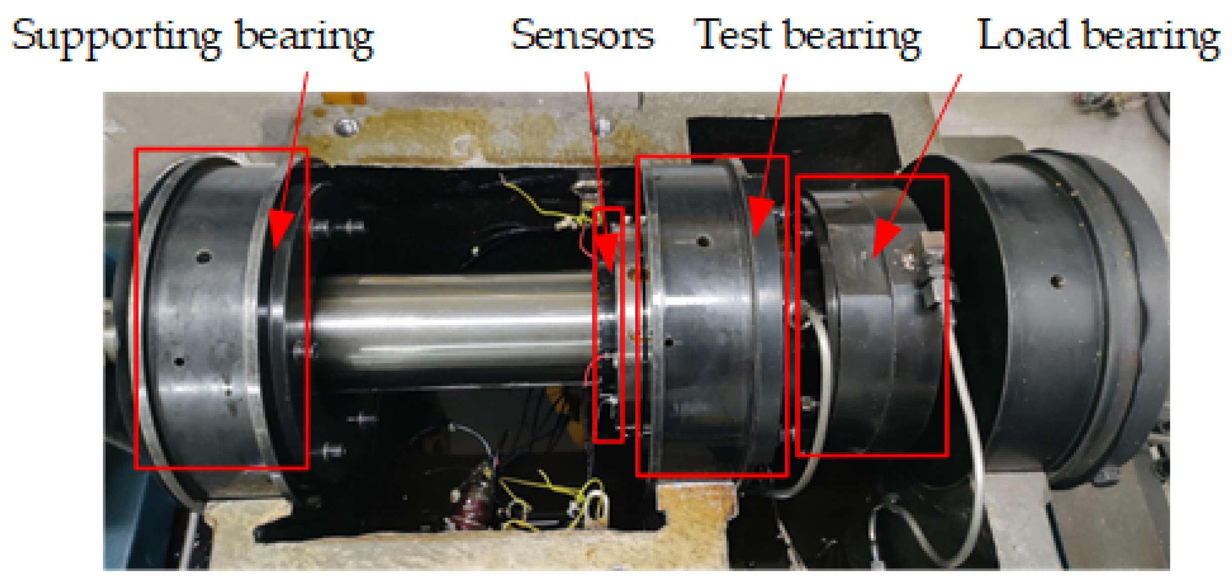
A diagram of the physical installation of the test bearing is illustrated in
Figure 11. A cantilever structure was utilized, with the loading bearing positioned at the cantilever end of the spindle, while the test bearing was situated at the fulcrum of the spindle and the supporting bearing was placed at the left end of the spindle. Both the load bearing and the supporting bearing adopt deep groove ball bearings to ensure the system has sufficient precision and longevity.
The test apparatus mainly consists of the main body of the test apparatus, electrical control device, hydraulic loading device, lubrication device, computer monitoring and data acquisition system, etc.
The main body of the test apparatus is installed on a cast iron base. The electrical control device is mainly composed of a frequency converter and control circuit and is controlled through the electrical control cabinet, which is responsible for providing a power supply to the test apparatus and controlling the speed of the electric spindle to simulate the working conditions of the aero-engine main shaft bearing at different speeds. The hydraulic loading device includes an axial loading device and a radial loading device, mainly loaded by hydraulic pressure.
The lubrication device mainly consists of an oil tank, oil returning pump, and oil feed pump, primarily used for lubricating the test bearing. The oil supply and return pipes of the test bearing in the test apparatus are led out through the side wall on the same side of the base. The test bearing is lubricated via under-race lubrication and features a self-contained oil return chamber. The oil returning pump, driven by the oil return motor, pumps the lubricating oil back to the oil tank. The computer monitoring and data acquisition system primarily consists of a computer and data acquisition instrument, which are mainly used for setting, processing, and recording test parameters. Additionally, it can monitor the test process and automatically shut down in case of anomalies (such as excessive vibration or high temperature of the test apparatus) to ensure the safety of the test apparatus and the test bearing.
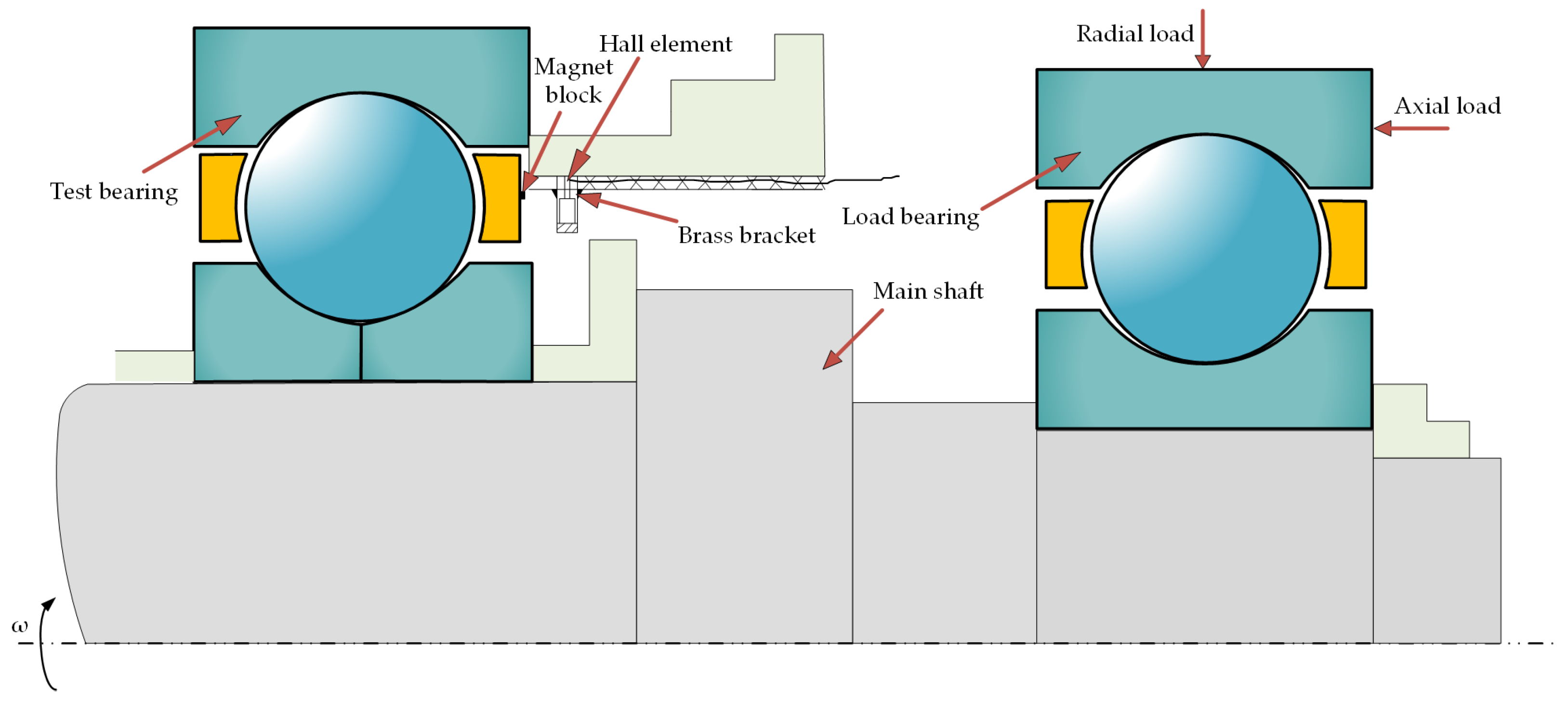
Figure 12 shows the schematic diagram of the test principle. The axial and radial loads are directly applied to the load bearing through the axial and radial loading devices in
Figure 10, and then transmitted to the test bearing. When a radial load is applied to the outer ring of the load bearing, since the loading bearing is mounted at the cantilever end of the spindle and the test bearing is mounted at the fulcrum of the spindle, the radial load on the test bearing can be calculated through force balance analysis based on the mounting positions of the load bearing and the test bearing on the spindle. Both the load bearing and the supporting bearing at the two ends of the spindle are deep groove ball bearings, with the supporting bearing having a larger axial clearance and the outer ring of the load bearing not being fixed. When an axial load is applied to the outer ring of the load bearing, the load bearing transmits the axial load to the spindle, while the supporting bearing is not preloaded. Therefore, the axial load applied to the load bearing entirely acts on the test bearing. The test spindle is connected to the electric spindle in
Figure 10 through a coupling. The rotation of the electric spindle drives the rotation of the test spindle and the test bearing. The cage is embedded with magnets, and the rotational speed of the cage during the test is measured by magneto-sensitive Hall elements.
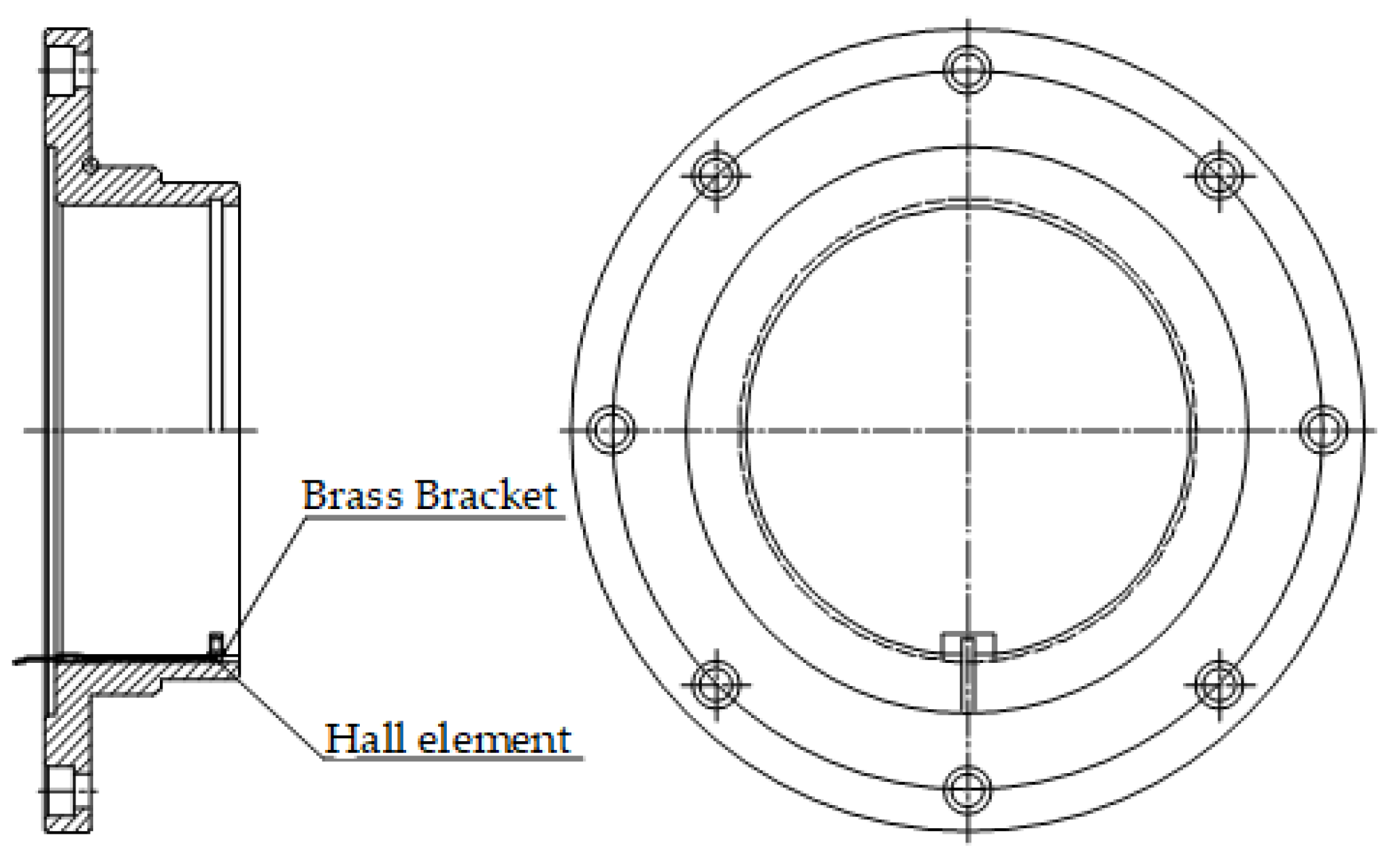
The installation position of the Hall element on the retainer is shown in
Figure 13. The measuring element is located within the brass material bracket on the inner side of the compression end cover, and the collected information is output through three signal transmission lines arranged in adjacent grooves.
Figure 14 illustrates the mounting positions of the magnet blocks. Two magnet blocks were symmetrically positioned on the cage reference surface at intervals of 180°, and they were installed in opposite directions. The sensing device is the Hall element. The working principle is as follows: during testing, the magnet blocks rotate at high speeds with the cage, generating pulse signals as they pass by the sensor. The rotational speed is displayed by a digital instrument that receives pulse signals, and the received signals are connected to the industrial control computer via a serial port, automatically displaying and saving the rotational speed. During the usage process, the cage rotation speed determined by the aforementioned method can be compared and calibrated using a dedicated tachometer stroboscope. Measurement uncertainties include the improper adjustment of the Hall element’s measurement distance during installation and the potential demagnetization of the magnetic block in high-temperature environments, which may affect the accuracy of the measurement results. Under the temperature conditions of this test, the magnetic block can function normally, and the installation position of the Hall element is measured during installation to ensure that the measurement distance of the Hall element is met.
The cage slip rate is calculated using the following formula:
where
is the measured cage speed;
is the theoretically calculated cage speed, with
, where
is inner ring speed;
is the ball diameter;
is the contact angle; and
is the pitch diameter of the bearing.
The cage slip test was conducted based on the parameters of the test bearing, as shown in
Table 3. The lubricating oil utilized in the test was 4106 aviation lubricating oil, and the relevant parameter information of the lubricant is shown in the first table in
Section 4. The working condition parameters of the test group were then measured and are detailed in
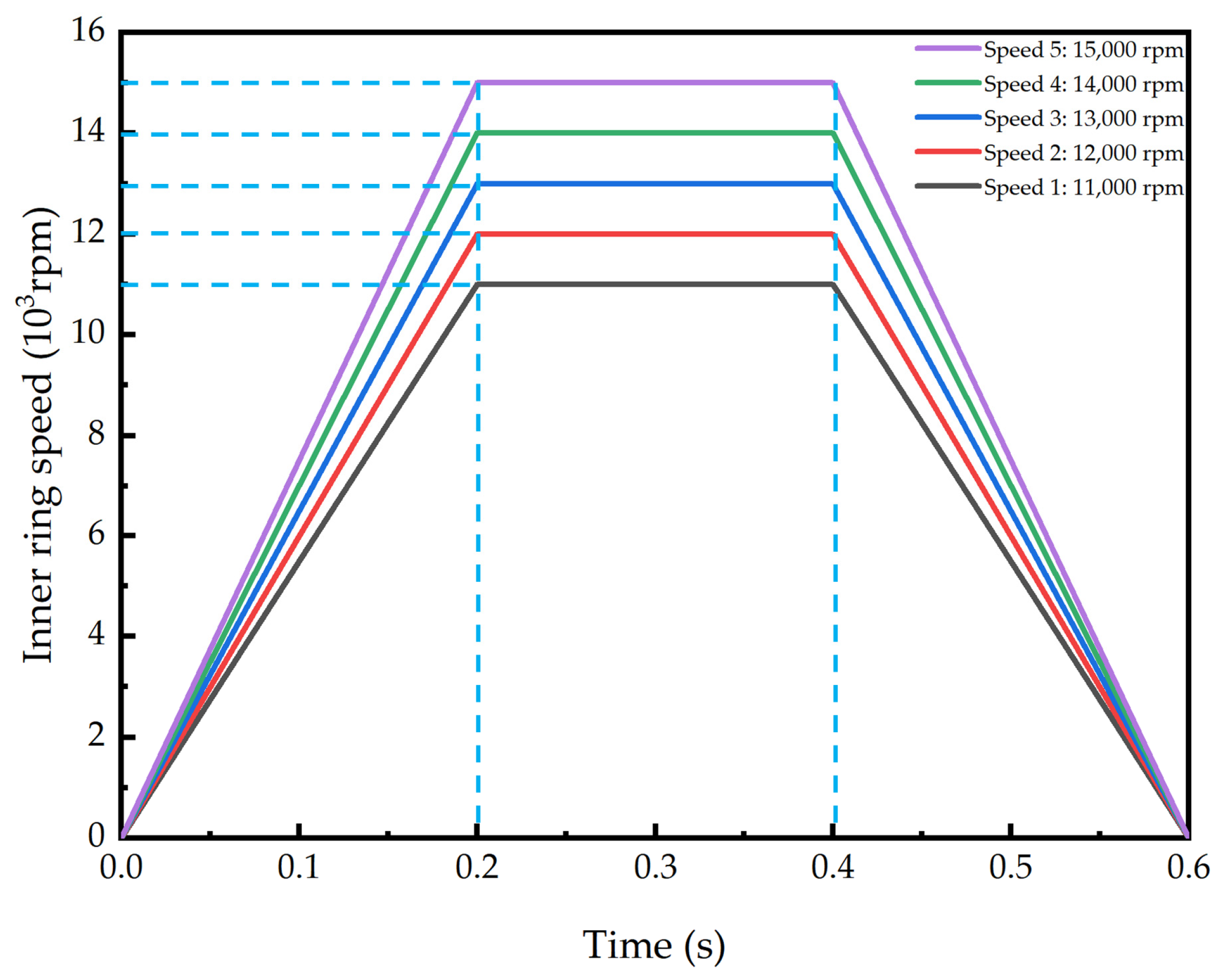
Table 4. The test time was set as follows: considering the limitations of the test apparatus and the safety of the test, after reaching the designated initial speed of 4000 rpm and maintaining stable operation for 120 s, the acceleration and deceleration test was initiated, the durations for both acceleration and deceleration were 10 s. Following this, subsequent acceleration and deceleration tests after ensuring stable operation for 110 s were commenced. The test is conducted in three cycles, and the average of the results from these three cycles is taken as the final result of the test. Considering the small degree of dispersion in the results of the three cycles, the final result of the test is deemed reliable.
Although consistency in each cycle test was meticulously maintained in this study, with the inlet oil temperature of the lubricant precisely controlled during the test process and the bearing accurately loaded via a precise hydraulic load device, there still exist certain uncertainties. Factors such as variations in the ambient temperature of the test environment, the initial phase of the bearing balls, and the distribution state of the internal lubricant within the bearing may have some influence on the test results.
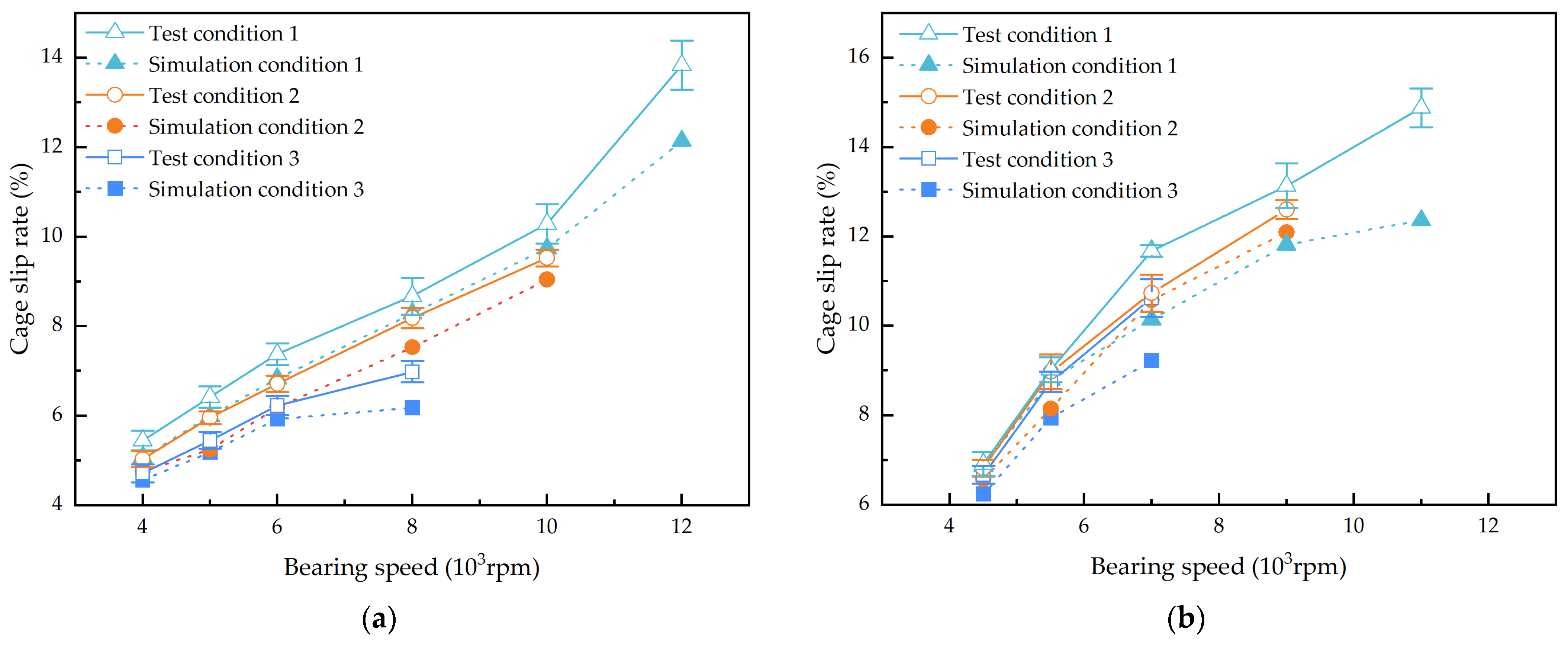
Figure 15 presents the comparison results of the cage slip rate between the test and the simulation. The trends of the simulation and test results are evidently consistent. The cage slip rate gradually increases with the bearing speed, and the overall numerical difference between the two is minimal, thereby verifying the accuracy of the established model. This model can be employed for subsequent analyses of the dynamic characteristics of the bearing. In
Figure 15, the simulated slip rate is slightly lower than the experimental slip rate. The primary sources of error are attributed to two factors: first, the theoretical simulation model employs partial theoretical assumptions and empirical formulas, and cumulative errors are generated during the numerical integration process; second, the measurement of the cage speed is also influenced by factors such as the vibration of the test device, leading to a deviation between the slip rate and the theoretical calculation.
The test data and simulation results of the cage slip rate under three load conditions were further compared, and the error percentages for both steady-state and unsteady-state conditions were calculated separately, as presented in
Table 5 and
Table 6.
As shown in
Table 5 and
Table 6, the maximum error between the simulation results and the test results for the cage slip rate does not exceed 20%, indicating that the simulation results are consistent with the test results within a 20% error margin. Under the test operating conditions, this simulation analysis model can predict the cage slip rate measured in the tests.


