Abstract
In response to the need to optimize the performance of copper–graphite current-carrying friction materials, spark plasma sintering (SPS) technology was used to prepare copper–graphite composite materials with different graphite orientations. A self-made current-carrying friction testing machine was used to study the effect of graphite orientation on the current-carrying friction performance of copper–graphite composites. The results showed that as the graphite orientation increased, the current-carrying friction performance of the copper–graphite composites initially improved and then deteriorated. The performance was optimal when the graphite orientation of the 7.5 wt% graphite–copper composite was 90°, primarily constrained by the wear rate. The main wear mechanism was furrowing, and graphite enrichment occurred on the worn surface, where the graphite content on the wear surface was higher than that in the bulk material. The degree of enrichment varied under different wear mechanisms. The graphite content near the entry region of the friction surface was significantly lower than that near the exit region.
1. Introduction
Copper–carbon composites, commonly used as current-carrying friction materials, are extensively applied in various fields such as switch contacts, motor brushes, and contact line/sliding plate systems [1,2,3]. With the advancement of technology, the service conditions of copper–carbon composites have become increasingly demanding, and the operating environments have grown more complex. For example, with the rapid development of high-speed rail, friction materials such as pantograph sliding plates are required to withstand higher speeds and electrical current loads, with speeds exceeding 300 km/h and maximum current loads exceeding 1000 A [4,5]. Therefore, further investigation of the service performance of copper–carbon composites is urgent [6,7].
The main factors affecting the current-carrying friction performance of copper–carbon composite materials include the phase enhancement, matrix, preparation process, content, morphology, and distribution [8,9,10]. Jing Zhao et al. [11] successfully prepared Cu/graphene composite materials with uniformly distributed graphene in the copper matrix by combining electroless plating and powder metallurgy techniques. The results show that incorporating graphene improves the friction-reduction and wear-resistance properties of the Cu–graphene composites. Linying Zhu et al. [12] prepared copper–graphene composite materials using foam copper with a thickness of 15–30 μm and a porosity of 97%, and studied the effects of foam copper on the mechanical and tribological properties of the copper–graphene composites. The results show that adding foam copper improved the material’s hardness and bending strength, helped reduce abrasive wear, and decreased the friction coefficient and wear rate. Adrien Morvan et al. [13] studied a new powder processing method (PPM) based on a hybrid technique of resonant acoustics (RA). By comparing PPM with commonly used methods in the literature, they found that PPM reduces defects in the graphite–carbon lattice and the oxygen content in the final composite material, thereby improving the mechanical properties of copper–graphene composites. Jaroslav Kovacik et al. [14] prepared copper–graphene composite materials with graphite volume fractions ranging from 0 to 50%. They investigated the effect of graphite content on the friction and wear performance of copper–graphene composites. As the graphite content increased, the friction coefficient initially decreased, stabilized after reaching a critical value, and the wear rate continued to decrease. However, there are few research reports on the influence of phase enhancement orientation on the current-carrying friction performance of copper–carbon composites.
Our research group has previously conducted studies on the sintering process, graphite content, and initial powder particle size optimization for copper–graphite composites used in current-carrying friction [15,16,17]. A reasonable sintering process can significantly improve the current-carrying friction performance of copper–graphite composites. Based on previous research, this study prepares copper–graphite composites with different graphite orientations (the angle between the flake graphite and the friction direction, Figure 1) and investigates the effect of graphite orientation on the current-carrying friction performance of copper–graphite composites.
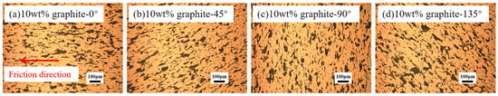
Figure 1.
Metallographic image of the cross-section of the sales sample.
2. Materials and Methods
2.1. Materials
Copper–graphite composites with different graphite contents (5 wt%, 7.5 wt%, and 10 wt%) were prepared using electrolytic pure copper powder with a particle size of 200 mesh and natural graphite powder (Qinghe County Nuotu Welding Material Co., Ltd., Renqiu City, China), employing the spark plasma sintering (SPS) technique. The powder metallurgy process involved the following: first, mixing the copper powder and graphite powder in a roll ball mill according to a predetermined mass ratio (at 70 r/min for 12 h); then, sintering the mixture using the SPS process (with a vacuum of <5 Pa) to prepare the composite material. The heating protocol for the sintering process was as follows: a sintering pressure of 25 MPa, heating rate of 100 °C/min, holding at 400 °C for 1 min, then raising the temperature to 780 °C and holding for 7 min, followed by furnace cooling. The sintered material had dimensions of Φ 28 mm × 15 mm, with the graphite alignment angle at 0°, and a density of 95% ± 2%. The material was then cut into specimens with dimensions of Φ4 mm × 15 mm, with a graphite orientation of 0°, 45°, 90°, and 135°, to be used for pin-on-disk testing (Figure 1). The disk specimen was made of brass (C28000, Luoyang Copper Processing Group Co., Ltd., Luoyang, China), with dimensions of Φ 100 mm × 10 mm.
2.2. Experimental Methods
The current-carrying friction test was conducted on a self-made current-carrying friction wear testing machine (schematic shown in Figure 2). The friction pair was of the pin-on-disk type, with the applied current entering through the specimen holder and flowing through the disk specimen before exiting through the pin specimen. In the experiment, the applied load was 3N, the current was 8A, the linear speed was 2.2 m/s, and the test duration was 15 min. Before the experiment, the pin specimen was polished with 800# sandpaper to ensure full contact between the pin and disk specimens. The experiment was conducted under room temperature and atmospheric conditions.
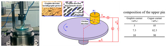
Figure 2.
Experimental schematic diagram.
The real density of the copper–graphite composites was determined using the Archimedes’ drainage method, and the density was then calculated [18]. The conductivity was measured using the Sigma2008B/C (Shanghai Gaozhi Precision Instruments Co., Ltd., Shanghai, China) digital eddy current metal conductivity meter (Shanghai Gaozhi Precision Instrument Co., Ltd., Shanghai, China). Hardness testing was conducted using the HV-1000A Vickers hardness tester (Laizhou Huayin Testing Instruments Co., Ltd., Laizhou, China).
After the current-carrying friction wear test, the wear surface was observed using a JSM-5610LV scanning electron microscope (SEM, Tokyo, Japan), and elemental analysis was performed using energy dispersive spectroscopy (EDS). At the same time, the three-dimensional morphology of the wear surface was observed using the Rtec MFT-5000L 3D profilometer (Rtec, San Jose, CA, USA).
The current-carrying friction wear tests use the average friction coefficient and mass wear rate to measure the friction wear performance of the composite materials, while the current-carrying efficiency and current-carrying stability are used to measure the current-carrying performance of the composite materials.
The calculation formula for current carrying efficiency is as follows:
where η is the current-carrying efficiency (%); is the average operating current (A); and is the rated current (A).
The calculation formula for current carrying stability is as follows:
where is the instantaneous current value, is the average operating current (A); and δ is the current-carrying stability parameter, dimensionless.
3. Results
3.1. The Effect of Graphite Orientation on the Physical Properties of Copper–Graphite Composites
Figure 3a shows the hardness variation curve of copper–graphite composites at different graphite orientations. As seen in the figure, the hardness of the material first increases and then decreases as the graphite orientation increases. As the graphite content increases, the hardness of the material gradually decreases. When the graphite angle is 90°, the hardness of all the materials is at its highest. The author believes that this is because the area proportion of graphite on the surface affects the hardness, and the area proportion of graphite on the material’s surface is minimal when the graphite orientation is 90°.
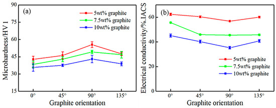
Figure 3.
Hardness and Electrical Conductivity of Copper–Graphite Composites with Different Graphite Orientations: (a) Hardness; (b) Electrical Conductivity.
Figure 3b shows the electrical conductivity variation curve of copper–graphite composites at different graphite orientations. The figure shows that as the graphite orientation increases, the electrical conductivity of the material first decreases and then increases. As the graphite content increases, the electrical conductivity of the material gradually decreases. When the graphite orientation is 90°, the electrical conductivity of all the materials is at its lowest (since the eddy current method was used for testing in this experiment, when the graphite orientation is 90°, the flake graphite in the vertical direction is the greatest obstruction to the testing eddy current, resulting in a lower electrical conductivity).
3.2. The Effect of Graphite Orientation on the Current-Carrying Friction and Wear Properties of Copper–Graphite Composites
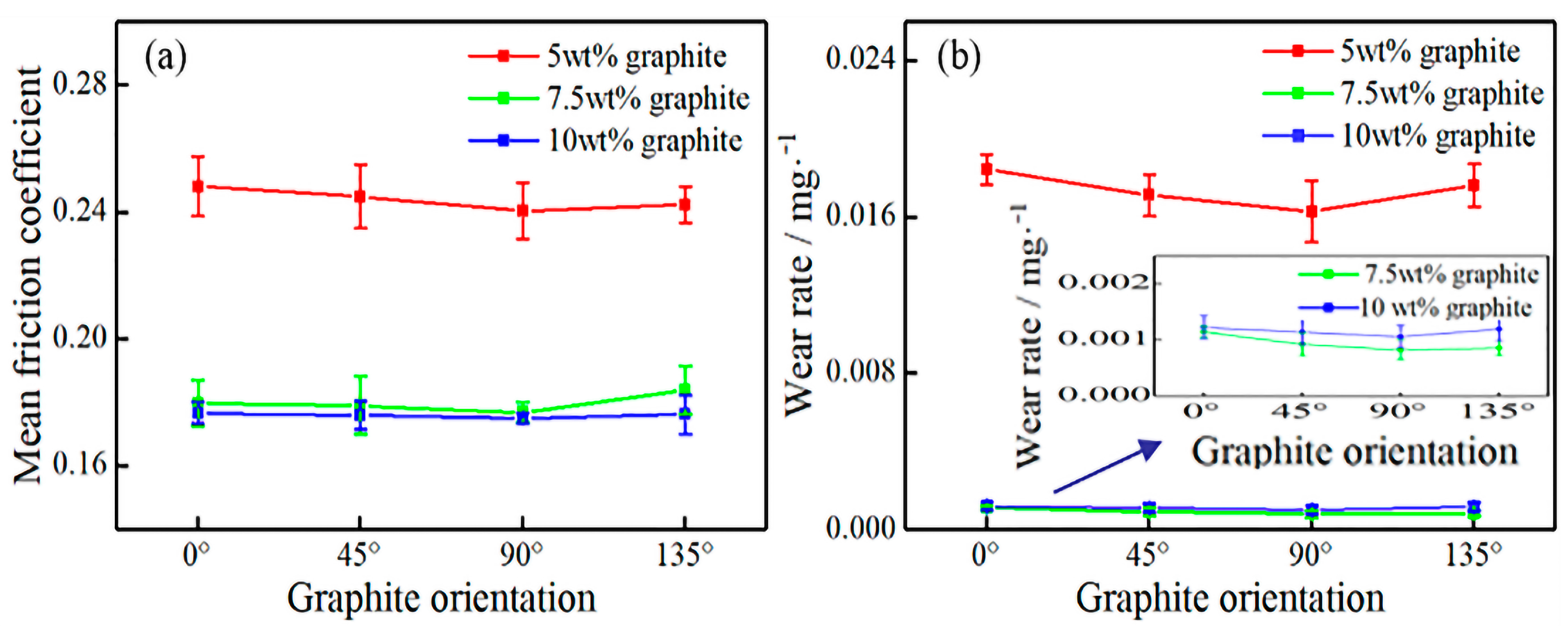
Figure 4a shows the average friction coefficient curve of copper–graphite composites during current-carrying friction at different graphite orientations. As seen in the figure, with the increase in graphite orientation, the average friction coefficient first decreases and then increases. When the graphite orientation is 90°, the average friction coefficient of the material is at its lowest, reduced by 8% to 15% compared to that at 0°. As the graphite content increases, the average friction coefficient gradually decreases.
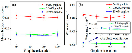
Figure 4.
Friction and wear performance of copper–graphite composites with different graphite orientations during current-carrying friction: (a) average friction coefficient; and (b) wear rate.
Figure 4b shows the wear rate curve of copper–graphite composites during current-carrying friction at different graphite orientations. The figure indicates that as the graphite orientation increases, the wear rate first decreases and then increases. When the graphite orientation is 90°, the wear rate of the material is at its lowest, reduced by 11% to 20% compared to that at 0°. As the graphite content increases, the wear rate first decreases and then increases.
In copper–graphite composites, graphite forms a continuous, conductive, lubricating film on the friction surface, which helps the friction pair operate smoothly. However, when the graphite content is low, the lubricating effect of graphite weakens, leading to an increase in the friction coefficient and wear rate. This phenomenon was also confirmed by the research of Jaroslav Kovacik [14] and others.
3.3. The Effect of Graphite Orientation on the Current-Carrying Performance of Copper–Graphite Composites
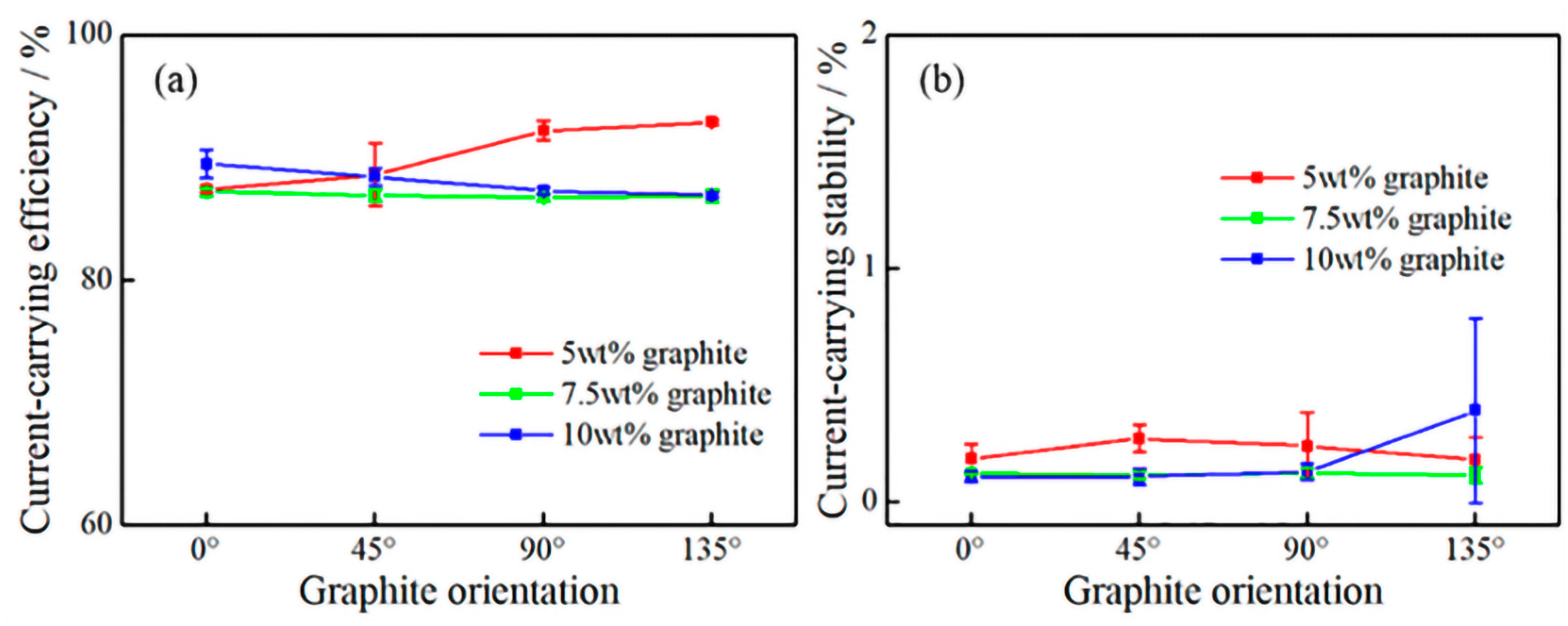
Figure 5 presents the current-carrying efficiency and stability curves of copper–graphite composites with different graphite orientations during the current-carrying friction process. It can be observed from the figure that as the graphite orientation and content increase, the current-carrying efficiency of the material varies within the range of 86.8–92.9%, and the current-carrying stability varies between 0.15–0.39%. This result indicates that the current-carrying efficiency and current-carrying stability of the friction pair perform excellently; therefore, it can be concluded that under these experimental conditions, the variations in graphite orientation and graphite content have minimal impact on the current-carrying performance of the material. The difficulty of graphite detaching from the bulk material and transferring to the friction surface to form a graphite film is greatest when the graphite angle is 135°. When the graphite content is higher, it is easier to form a continuous–conductive–lubricating graphite film on the wear surface. The combined effects of these two factors lead to significant differences in current-carrying stability under the same experimental conditions.
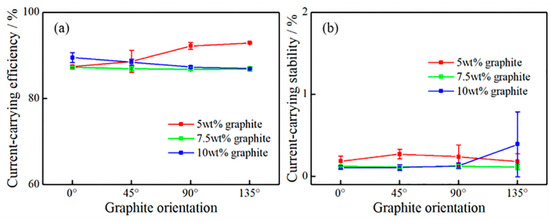
Figure 5.
Current-carrying performance of composites with different graphite orientations during current-carrying friction: (a) current-carrying efficiency; and (b) current-carrying stability.
In terms of performance, the copper–graphite composite materials used in the experiments exhibit good current-carrying properties, while wear performance becomes the primary factor limiting the performance (life) of the friction pairs.
3.4. The Effect of Graphite Orientation on the Current-Carrying Friction and Wear Behavior of Copper–Graphite Composites
Figure 6 shows the macro photos of the worn surfaces of the pin samples. From the figure, it can be seen that the worn surfaces of all pin samples consist of mechanical wear regions and severe arc erosion regions (marked by red dashed lines in the figure). The mechanical wear region constitutes the majority of the total wear area, while the arc erosion region occupies a smaller portion and is mainly distributed near the exit and edges of the worn surface. As the graphite orientation increases, the area of the arc erosion region first decreases and then increases [19,20,21]. Meanwhile, as the graphite content increases, the area of the arc erosion region in the material gradually decreases. Therefore, it can be concluded that changes in graphite orientation have a certain impact on the electrical damage to the material.
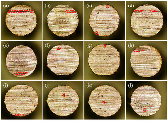
Figure 6.
Macro photos of the wear surfaces of the pin samples: (a) 0° (5 wt% graphite); (b) 45° (5 wt% graphite); (c) 90° (5 wt% graphite); (d) 135° (5 wt% graphite); (e) 0° (7.5 wt% graphite); (f) 45° (7.5 wt% graphite); (g) 90° (7.5 wt% graphite); (h) 135° (7.5 wt% graphite); (i) 0° (10 wt% graphite); (j) 45° (10 wt% graphite); (k) 135° (10 wt% graphite); and (l) 135° (10 wt% graphite).
3.5. Three-Dimensional Morphology of the Wear Surfaces of Composites with Different Graphite Orientations
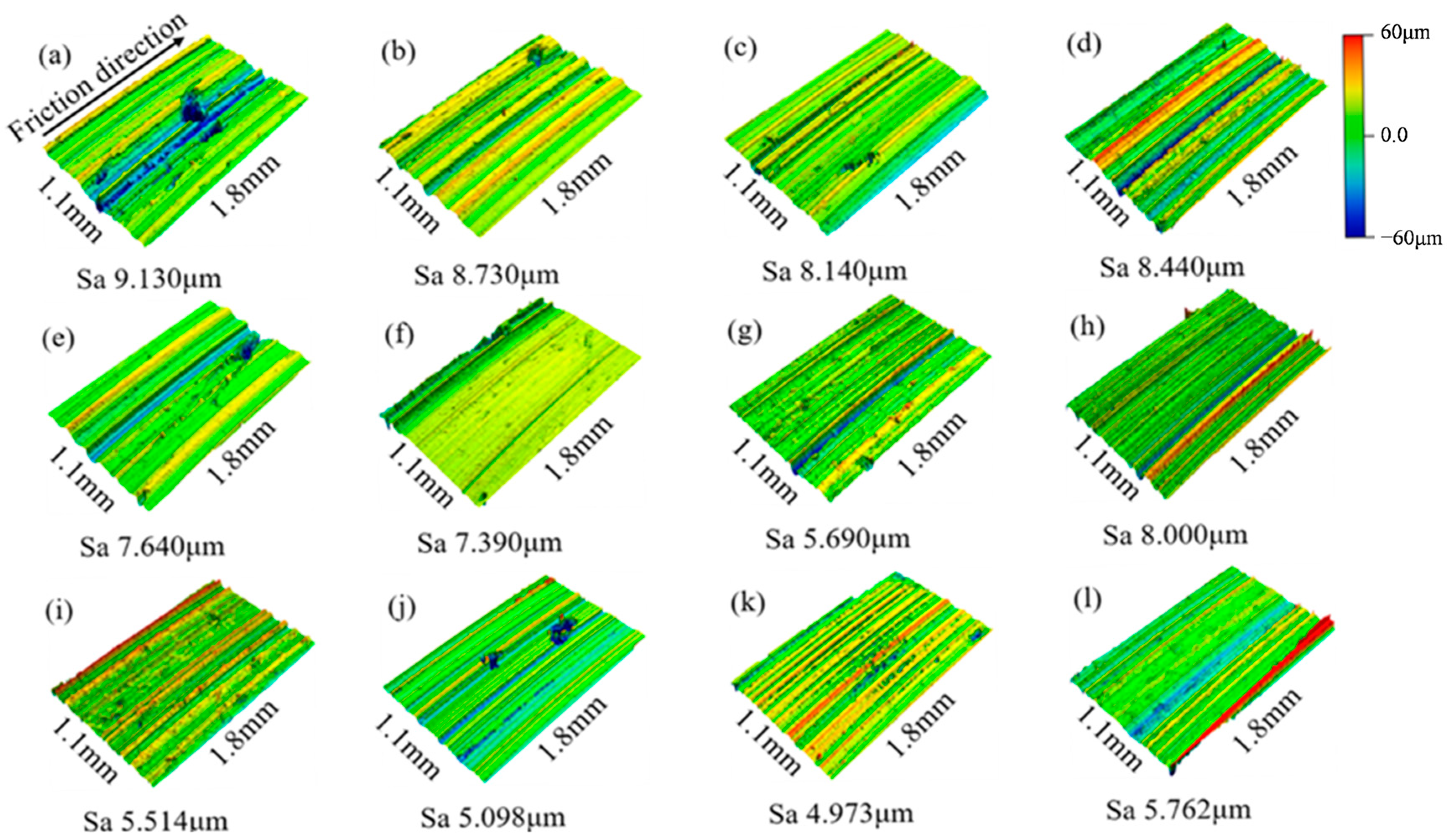
Figure 7 shows the three-dimensional morphology and roughness of the worn surface of the pin samples. From the figure, it can be seen that all the worn surfaces are primarily characterized by furrows. As the graphite orientation increases, the surface roughness of the wear decreases first and then increases, reaching its minimum when the graphite orientation is 90°. With the increase in graphite content, the surface roughness of the wear gradually decreases.

Figure 7.
Three-dimensional morphology of the wear surfaces of the pin samples: (a) 0° (5 wt% graphite); (b) 45° (5 wt% graphite); (c) 90° (5 wt% graphite); (d) 135° (5 wt% graphite); (e) 0° (7.5 wt% graphite); (f) 45° (7.5 wt% graphite); (g) 90° (7.5 wt% graphite); (h) 135° (7.5 wt% graphite); (i) 0° (10 wt% graphite); (j) 45° (10 wt% graphite); (k) 135° (10 wt% graphite); and (l) 135° (10 wt% graphite).
3.6. Analysis of the Wear Surface Behavior of Composites with Different Graphite Orientations
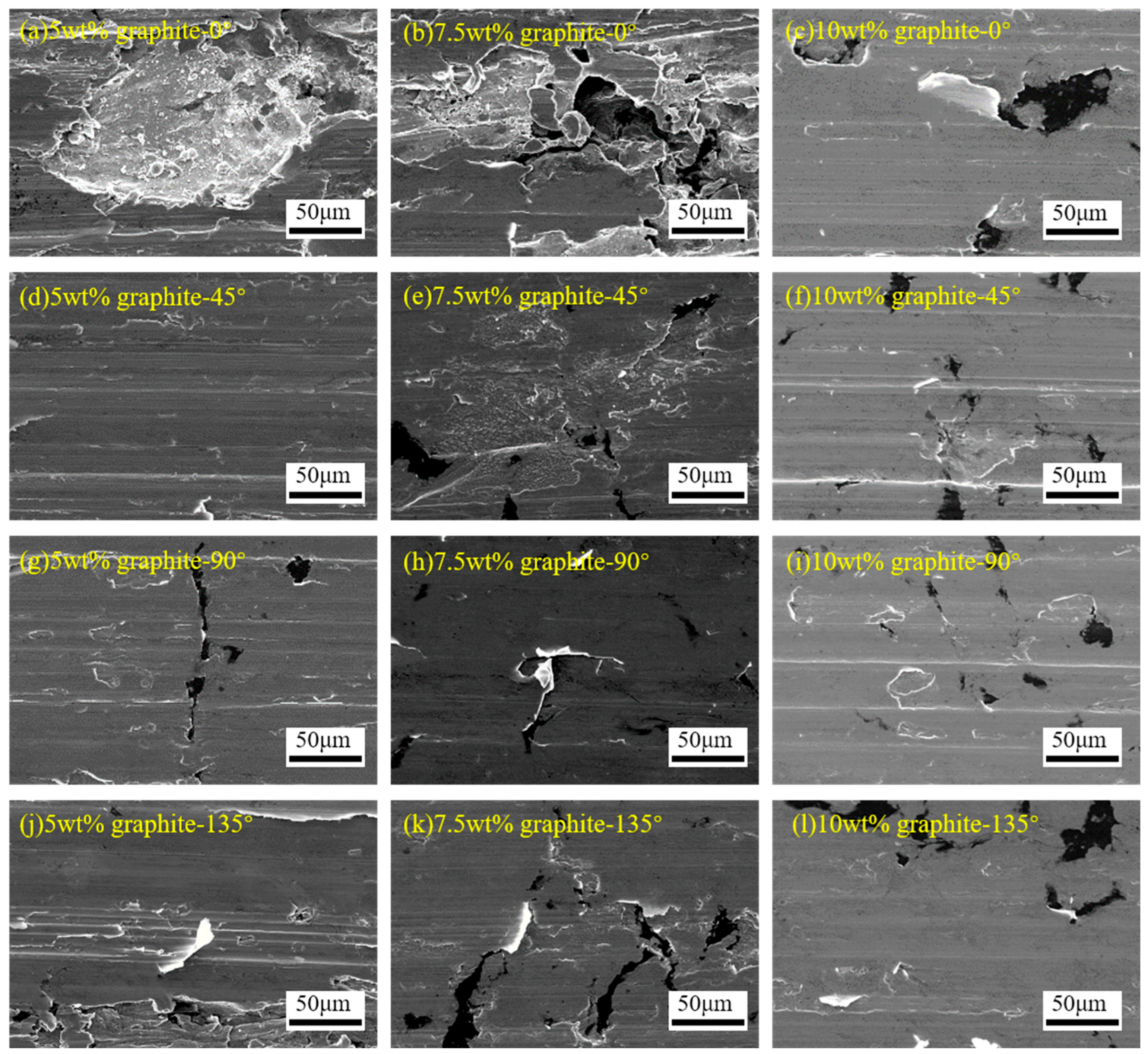
Figure 8 shows SEM images of the worn surfaces of materials with different graphite contents and angles. The worn surface is primarily characterized by furrows, along with adhesive tearing, exfoliation pits, and arc erosion features. Further analysis shows that there are two sizes of exfoliation pits [22,23,24]. One type is deep exfoliation pits (as shown in Figure 8a, with a diameter of about 150 μm, where arc erosion occurs within the pit), which form due to poor interfacial bonding of the material and are primarily found on wear surfaces with a graphite orientation of 0°. The other type is shallow exfoliation pits (as shown in Figure 8c, with a diameter of about 30 μm); the author believes the formation mechanism is as follows: during the furrow process, the metal material undergoes plastic deformation and then fractures, the fractured part cannot bond with the matrix due to the presence of graphite, leading to its detachment and the formation of the exfoliation pit. Additionally, as the graphite content increases, both the depth and diameter of individual delamination pits on the wear surface decrease. Deep delamination pits were observed on the wear surfaces of composites with 5 wt% and 7.5 wt% graphite content and an orientation angle of 0°, while only shallow delamination pits were observed on other materials. As the graphite orientation increases, the wear surface gradually becomes smoother, with the total area of shallow delamination pits first decreasing and then increasing, reaching its minimum at a 90° orientation.
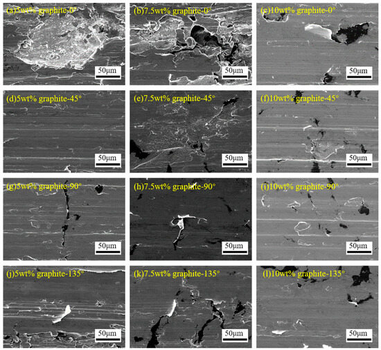
Figure 8.
SEM images of the wear surfaces of materials with different graphite contents and orientations.
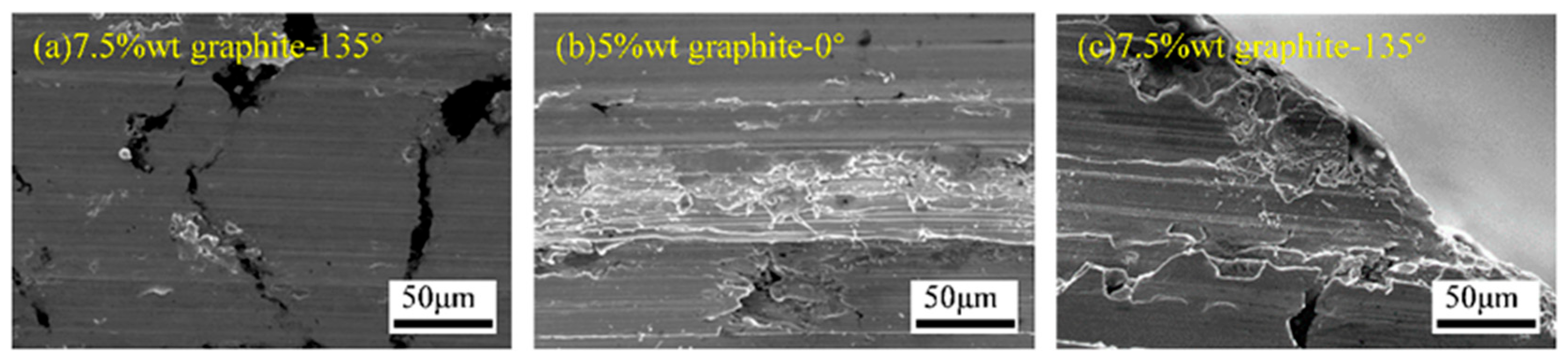
Figure 9a shows the arc erosion marks under the test condition of 7.5 wt%-135°. It can be seen that individual spherical particles are scattered on the friction surface, generally believed to be metal balls formed by splashing [25]. Figure 9b shows the arc erosion marks under the test condition of 5 wt%-0°. From the figure, it can be seen that arc erosion occurs at the edge of the rolled plastic deformation, forming a molten pool and producing strip and spherical splashes. Figure 9c shows the arc erosion marks under the test condition of 7.5 wt%-135° [26]. It can be observed that a large area of arc erosion marks appears at the exit of the friction surface and even on the side. In summary, although the arc erosion area on the wear surface is small, traces of arc melting and splashing can still be observed, distributed on the wear surface and the side of the specimen at the exit.
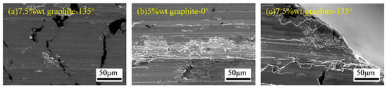
Figure 9.
Arc erosion traces: (a) spherical particles; (b) and (c) molten splashes.
3.7. Graphite on the Wear Surface
Based on the previous research of the research group, it was found that there is an uneven damage phenomenon during the current-carrying friction process. Significant differences are observed between the exit and entry regions along the direction of friction. Therefore, the statistical analysis of the graphite content was performed separately for the two regions, A and B, which exhibit significant differences on the wear surface. Figure 10 shows the graphite content in the A and B selected areas on the wear surface under current-carrying friction conditions with four graphite orientations for three materials. It can be seen from the figure that the graphite content in all the selected areas is greater than 22 wt%, far exceeding the graphite content from 5 wt% to 10 wt% in the bulk material. On the same specimen, the graphite content in area A is between 4.8 wt% and 8.2 wt% higher than in area B, and in the experiments, the graphite content in all A selections is significantly higher than in area B. As the graphite content increases, the graphite content in both areas A and B increases, but the increment is between 0.9 wt% and 4.1 wt%. The effect of graphite orientation on surface graphite content is unclear.
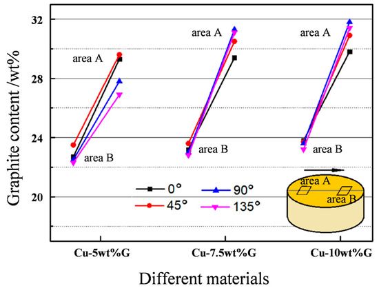
Figure 10.
Graphite content at different positions on the worn surface (EDS, ±0.4).
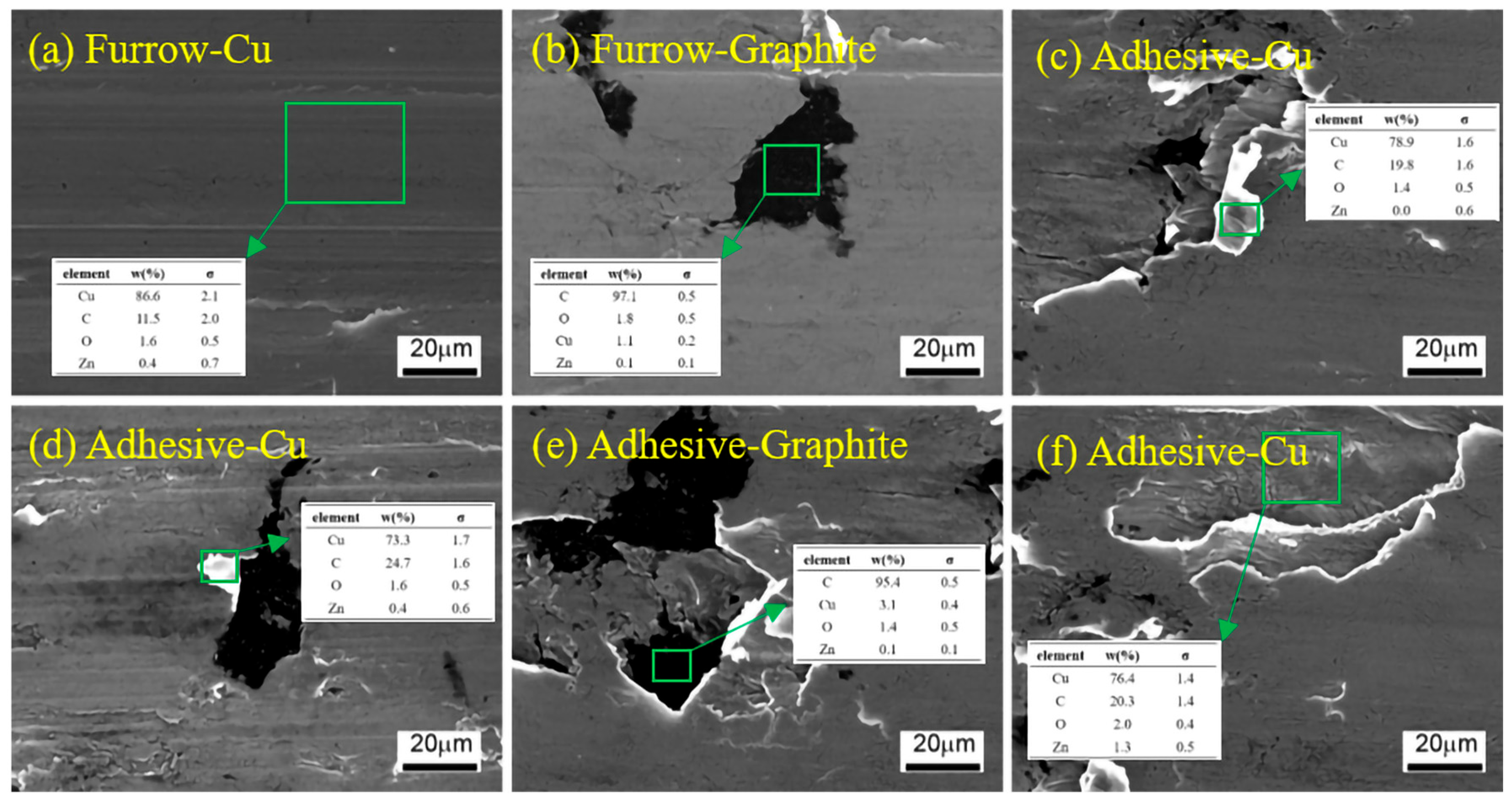
Figure 11 shows the graphite content on typical mechanical wear surfaces [22,27,28]. Figure 11a,b show the elemental content in the metal and graphite regions under the furrow morphology, with further statistical analysis indicating that the graphite content in the graphite region under the furrow morphology is in the range of 95.6 wt%~97.1 wt%, while the graphite content in the copper region under the furrow morphology is in the range of 10.4 wt%~17.1 wt% across three experimental materials and four graphite orientations. Figure 11c,d show the graphite content on the folded surface after adhesive tearing, with further statistical analysis indicating a graphite content between 19.8 wt% and 24.7 wt%. Figure 11e,f show the graphite content in the exposed area after adhesive tearing, where the graphite content in the graphite region is similar to that in the graphite region under the furrow morphology, and the graphite content in the copper region is between 17.8 wt% and 21.4 wt%. The results of the surface graphite content show no obvious relationship with the graphite content and graphite orientation in the bulk material.

Figure 11.
Graphite content on typical mechanical wear surfaces.
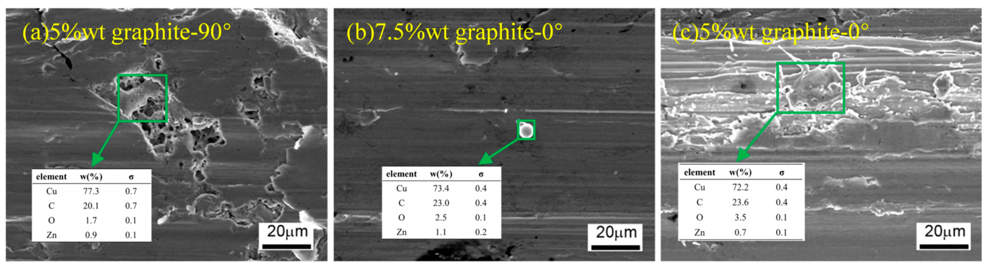
Figure 12 shows the graphite content in three typical arc erosion morphologies [2,27,28]. Figure 12a shows the graphite content in the melting, with a graphite content of 20.1 wt%, far exceeding the 5 wt% graphite content in the bulk material matrix. Figure 12b shows the graphite content in the splashing particles, with a graphite content of 23.0 wt%, far exceeding the 7.5 wt% graphite content in the bulk material matrix. Figure 12c shows the graphite content in the splashing area, with a graphite content of 23.6 wt%, far exceeding the 5 wt% graphite content in the bulk material matrix.
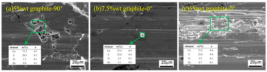
Figure 12.
Graphite content in three typical arc erosion morphologies.
4. Discussion
The damage mechanisms of copper–graphite composites used in current-carrying friction generally include adhesive tearing, furrow, particle impact, melting, and splashing. When the friction run is in good condition, with excellent current-carrying and frictional wear performance, the primary mechanical damage observed on the wear surface is furrow, while the form of arc erosion includes melting and splashing, with mechanical damage being the predominant type [29,30].
Graphite content and graphite orientation influence whether a continuous–conductive–lubricating graphite film can form on the friction surface, and these factors determine the current-carrying friction wear performance. It is widely believed that when graphite forms a continuous, conductive, lubricating film on the friction surface, it helps the friction pair operate smoothly, thereby optimizing the material’s service performance [31,32].
The wear surface is primarily composed of a mechanical wear region and an arc erosion region, with the mechanical wear region dominating. The wear mechanism in this region is primarily characterized by furrowing. As the graphite content increases, the total area of the mechanical wear region slightly increases, and the surface roughness of the wear decreases gradually. However, as the graphite angle increases, the total area of the mechanical wear region first increases and then decreases, ultimately resulting in a smaller total area. The wear surface roughness first decreases and then increases. In the mechanical wear region, graphite acts as a lubricant, preventing adhesive tearing by distributing on the friction surface, thereby ensuring the smooth operation of the friction pair and suppressing arc formation. In the arc erosion region, the high temperature causes graphite to oxidize directly into gas, protecting the copper from oxidation and preventing the formation of non-conductive solid oxides. Additionally, graphite has some electrical conductivity, which prevents severe deterioration of surface conductivity. However, the further behavior of graphite on the friction surface remains unclear.
The graphite content on the surface and interface is significantly higher than that in the bulk material. This is because graphite has a layered structure with weak interlayer bonding. During the uniform mixing process, the graphite undergoes fragmentation and interlayer relative sliding. Additionally, because graphite and copper are completely non-wettable, graphite rarely enters the copper particles during mixing and sintering, instead distributing between metal particles in the form of adsorption and mechanical interlocking. During the current-carrying friction process, graphite particles undergo further fragmentation and interlayer sliding, with most of the graphite distributing on the wear surface, except for a small amount that oxidizes into gas or escapes from the friction surface. Therefore, graphite enrichment occurs on the wear surface.
Graphite enrichment mainly occurs in the copper regions of the wear surface. This is because the wear surface consists of graphite and copper regions and methods like adsorption and mechanical interlocking cannot further increase the graphite content in the graphite-dominant regions. The enrichment behavior in the copper regions is related to the specific location on the wear surface (i.e., the differences in selected areas shown in Figure 10) and is associated with different wear surface behaviors (Figure 11 and Figure 12). When the copper and graphite surfaces are exposed due to adhesive tearing and further adsorb graphite from the friction surface, the graphite content becomes relatively high (Figure 11c,d,f). This high content has a limit, as shown in Figure 11d, where even when completely torn from the graphite bulk, the content is only less than 25 wt%, whereas the graphite content in the graphite region is between 95.6 wt% and 97.1 wt%. In the furrow region, the furrow action causes plastic deformation of the copper material, creating new surfaces, which reduces the surface graphite content (Figure 11a).
Graphite enrichment also occurs in the arc erosion region. After the copper material melts and splashes, the complete non-wettability between graphite and copper results in graphite adhering to the metal surface through adsorption and mechanical interlocking, forming a graphite film and increasing the surface graphite content (Figure 12).
The amount of graphite on the macroscopic surface is also limited by the proportion of various typical surfaces to the total surface area.
The graphite content and graphite orientation in the bulk material affect the graphite content on the wear surface (Figure 10). Graphite in the bulk material serves as the source of graphite on the wear surface, thus directly influencing the graphite content on the wear surface. The graphite orientation affects the detachment of graphite from the bulk material and its transfer to the friction surface, as well as the interlayer sliding of graphite. It can be assumed that as the graphite orientation increases, the difficulty of individual graphite particles moving to the friction surface continuously increases. Therefore, it also affects the graphite content generated on the worn surface.
In summary, graphite on the friction surface serves as a lubricant, and its content is influenced by several factors, including the graphite content in the bulk material, graphite orientation, different forms of mechanical wear and their respective proportions, and arc erosion. There is a certain correlation between the graphite content on the worn surface and the current-carrying frictional performance, but it is not fully consistent. It is observed that the materials with graphite content of 7.5 wt% and 10 wt% in the bulk material both exhibit good performance, and the graphite content on the worn surface is also relatively high. However, it cannot be inferred from the surface graphite content that the best performance is achieved when the bulk graphite content is 7.5 wt% and the graphite orientation is 90°.
The current-carrying frictional wear performance of the bulk material is primarily influenced by surface behavior, as well as the strength and thermal conductivity of the matrix. Electrical conductivity is mainly affected by the size and quantity of conductive contact spots and the friction evolution process, i.e., the contact state during the current-carrying friction process and the smoothness of the tribo-pair running. It is also influenced by the properties of the matrix material (such as thermal conductivity and electrical conductivity). As the graphite orientation in the matrix increases, the hardness of the matrix material first increases and then decreases, while its electrical conductivity first strengthens and then weakens.
Current-carrying efficiency reflects the dynamic electrical conductivity of the tribological pair, which is primarily determined by the conductivity of the base material and the dynamic process of the tribological pair’s operation. Current-carrying stability reflects the fluctuation of current during the operation of the tribological pair, which is mainly determined by the dynamic process of the tribological pair’s operation. In this study, the conductivity of the material is influenced by the graphite content and the orientation of the graphite. The dynamic process of the tribological pair’s operation refers to the dynamic change process of the contact conductive spots (α spots) on the friction surface, from formation to development and ultimately to failure. In this study, the operation of the tribological pair mainly depends on three factors: 1. the smoothness of the tribological pair’s operation; 2. the graphite content on the friction surface; and 3. the presence of the electric arc. Therefore, the dynamic process of the tribological pair’s operation exhibits both regularity and randomness. For instance, with an increase in graphite content, the operation of the tribological pair becomes smoother [14]; however, the occurrence of the electric arc introduces randomness into the friction process [28]. Under different experimental conditions, the current-carrying friction dynamic process is influenced by various regular and random factors.
From the perspectives of current-carrying efficiency and stability, the current-carrying performance of the copper–graphite composite material used in the experiment is relatively good and can meet practical engineering demands. Wear performance has become the main factor limiting the tribological pair’s performance (lifespan). Under the influence of multiple factors, as the graphite orientation increases, the current-carrying frictional performance of the copper–graphite composite material first improves and then declines, with the optimal performance occurring when the bulk material contains 7.5 wt% graphite and the graphite orientation is 90°.
5. Conclusions
(1) As the graphite content and orientation increase, the average friction coefficient and wear rate first decrease and then increase, with optimal performance observed at a graphite content of 7.5 wt% and a graphite orientation of 90°. Under the experimental conditions, the current-carrying efficiency (86.8–92.9%) and stability (0.15–0.39%) of the friction pairs exhibit excellent performance. Therefore, in terms of performance, the copper–graphite composite materials used in the experiments have good current-carrying properties, with wear resistance being the primary factor limiting the performance (life) of the friction pairs.
(2) The wear surface primarily consists of the mechanical wear region and the arc erosion region. The wear form in the mechanical wear region is mainly furrowing. As the graphite content increases, the mechanical wear region slightly increases, and the surface roughness of the wear decreases gradually. As the graphite angle increases, the mechanical wear region first increases and then decreases, with a smaller total area, while the wear surface roughness first decreases and then increases.
(3) The wear surface exhibits a graphite enrichment, which serves as a lubricant. The amount of graphite is influenced by multiple factors, including the graphite content in the bulk material, graphite orientation, the different forms of mechanical wear and their respective proportions, and arc erosion. The graphite content on various typical wear surfaces is higher than that in the bulk material. The graphite content in the region near the inlet of the friction surface is significantly lower than that near the outlet. As the total graphite content in the bulk material increases, the graphite content on the wear surface shows an increasing trend. The increase in graphite orientation affects the graphite content on the wear surface.
Author Contributions
Conceptualization, Z.Y.; Methodology, Z.Y.; Validation, W.L. and Y.S.; Formal analysis, W.L. and Y.S.; Investigation, W.L. and X.Z.; Resources, Y.Z.; Writing—original draft, Z.Y. and W.L.; Writing—review & editing, Z.Y.; Visualization, Y.S. and X.Z.; Supervision, Y.Z.; Funding acquisition, Y.Z. All authors have read and agreed to the published version of the manuscript.
Funding
This work was supported by the National Natural Science Foundation of China (U1804252) and the Key Scientific Research Project of Henan Province (22A430021).
Data Availability Statement
The data presented in this study are available on request from the corresponding author.
Conflicts of Interest
The authors declare no conflicts of interest.
References
- Guo, F.Y.; Gu, X.; Wang, Z.Y.; Wang, Y.; Wang, X. Simulation on Current Density Distribution of Current-Carrying Friction Pair Used in Pantograph-Catenary System. IEEE Access 2020, 8, 25770–25776. [Google Scholar] [CrossRef]
- Li, S.B.; Yang, X.; Kang, Y.Q.; Li, Z.Y.; Li, H.W. Progress on current-carry friction and wear: An overview from measurements to mechanism. Coatings 2022, 12, 1345. [Google Scholar] [CrossRef]
- Hung, P.V.; Bao, L.D.; Duong, N.T. Effect of Humid Tropical Climate and Electrical Current on the Electrical Sliding Wear Behavior of Graphite Brush in Motor. J. Tribol. 2023, 145, 031704. [Google Scholar] [CrossRef]
- JB/T 12252-2015; Brush for Wind Driven Generator. Machinery Industry Standards of the People’s Republic of China: Beijing, China, 2015. (In Chinese)
- Wu, G.N.; Dong, K.L.; Xu, Z.L.; Xiao, S.; Wei, W.F.; Chen, H.; Li, J.; Huang, Z.L.; Li, J.W.; Gao, G.Q.; et al. Pantograph–catenary electrical contact system of high-speed railways: Recent progress, challenges, and outlooks. Railw. Eng. Sci. 2022, 30, 437–467. [Google Scholar] [CrossRef]
- He, Z.J.; Ni, Z.R.; Wang, H.; Yang, Z.; Wei, W.; Wang, X.; Deng, L.; Wu, G. Effect of Magnetic Field on the Current-carrying Friction and Wear Performance of C/Cu Contact Pairs. In Proceedings of the 2021 International Conference on Electrical Materials and Power Equipment (ICEMPE), Chongqing, China, 11–15 April 2021. [Google Scholar] [CrossRef]
- Fu, Y.; Qin, H.; Xu, X.; Zhang, X.; Guo, Z. What are the Progresses and Challenges, from the Electrical Properties of Current-Carrying Friction System to Tribological Performance, for a Stable Current-Carrying Interface? J. Bio-Tribo-Corros. 2022, 8, 4. [Google Scholar] [CrossRef]
- Rajkumar, K.; Kundu, K.; Aravindan, S.; Kulkarni, M. Accelerated wear testing for evaluating the life characteristics of copper–graphite tribological composite. Mater. Des. 2011, 32, 3029–3035. [Google Scholar] [CrossRef]
- Yan, Y.F.; Kou, S.Q.; Yang, H.Y.; Shao, Y.; Qiu, F.; Shu, S.L. Synergistic optimization of mechanical and tribological properties of TiC modified copper-graphite composites by direct current in-situ sintering. Ceram. Int. 2023, 49, 27069–27078. [Google Scholar] [CrossRef]
- Su, Y.M.; Jiang, F.; Xiao, Z.Y.; Wu, F.; Long, M. Microstructure and tribological properties of copper/graphite composites with Ti3AlC2 addition prepared by rapid hot press sintering. Tribol. Int. 2024, 194, 109537. [Google Scholar] [CrossRef]
- Zhao, J.; Peng, Y.T.; Zhou, Q.G.; Zou, K. The current-carrying tribological properties of Cu/Graphene composites. J. Tribol. 2021, 143, 102101. [Google Scholar] [CrossRef]
- Zhu, L.Y.; Yi, M.; Wang, L.M.; Chen, S. Effects of foam copper on the mechanical properties and tribological properties of graphite/copper composites. Tribol. Int. 2020, 148, 106164. [Google Scholar] [CrossRef]
- Morvan, A.; Grosseau-Poussard, J.; Caillault, N.; Delange, F.; Roure, S.; Lepretre, P.; Silvain, J.-F. Powder processing methodology for fabrication of Copper/Graphite composite materials with enhanced thermal properties. Compos. Part A Appl. Sci. Manuf. 2019, 124, 105474. [Google Scholar] [CrossRef]
- Kováčik, J.; Emmer, Š.; Bielek, J.; Keleši, L.U. Effect of composition on friction coefficient of Cu–graphite composites. Wear 2008, 265, 417–421. [Google Scholar] [CrossRef]
- Ge, Y.X.; Yang, Z.H.; Sun, L.M.; Zhang, Y.Z.; Zhang, J.W. Effect of sintering temperature on properties of copper-graphite composite materials. Trans. Mater. Heat Treat. 2019, 40, 8–14. [Google Scholar]
- Yang, Z.H.; Ge, Y.X.; Zhang, X.; Shangguan, B.; Zhang, Y.; Wang, Y. Effect of Particle Size on Current-Carrying Friction and Wear Properties of Copper-Graphite Composites by Spark Plasma Sintering. Materials 2019, 12, 2825. [Google Scholar] [CrossRef]
- Yang, Z.H.; Ge, Y.X.; Zhang, X.; Shangguan, B.; Zhang, Y.; Zhang, J. Effect of carbon content on friction and wear properties of copper matrix composites at high speed current-carrying. Materials 2019, 12, 2881. [Google Scholar] [CrossRef]
- Lu, J.; Ma, C.; Zhang, L.; He, Z.; Guo, B.; Wei, J.; Zeng, D.; Li, W.; Liu, Y. Effect of normal load on damage mechanism of gradient copper-graphite composites under electric current. Wear 2025, 562, 205653. [Google Scholar] [CrossRef]
- Zhou, Y.K.; Du, M.D.; Zuo, X. Influence of Electric Current on the Temperature Rise and Wear Mechanism of Copper–Graphite Current-Carrying Friction Pair. J. Tribol. 2022, 144, 101701. [Google Scholar] [CrossRef]
- Liu, X.L.; Cai, Z.; Liu, S.T.; Wu, S.B.; Zhu, M.H. Influence of wear test parameters on the electrical contact performance of brass alloy/copper contactors under fretting wear. J. Mater. Eng. Perform. 2019, 28, 817–827. [Google Scholar] [CrossRef]
- Grandin, M.; Wiklund, U. Wear phenomena and tribofilm formation of copper/copper-graphite sliding electrical contact materials. Wear 2018, 398, 227–235. [Google Scholar] [CrossRef]
- Wen, S.Z.; Huang, P. Principles of Tribology, 2nd ed.; Tsinghua University Press: Beijing, China, 2017. [Google Scholar]
- Hao, W.; Xia, Y.; Yi, Z. Current carrying tribological properties of multi arc ion plated titanium nitride doped silver coating. Mater. Res. Express 2024, 11, 056401. [Google Scholar] [CrossRef]
- Rong, M.Z.; Ma, Q.; Wu, Y.; Xu, T.; Murphy, A.B. The influence of electrode erosion on the air arc in a low-voltage circuit breaker. J. Appl. Phys. 2009, 106, 023308. [Google Scholar] [CrossRef]
- Zhao, L.J.; Li, Z.B.; Shi, K.Y.; He, J.; Li, H. Electrical properties of nanocrystalline CuCr25 contact material. IEEE Trans. Compon. Packag. Manuf. Technol. 2012, 3, 625–632. [Google Scholar] [CrossRef]
- Liu, X.L.; Hu, M.J.; Li, Z.H.; Zhou, C.; Xiao, Q.; Yang, W.; Chen, D. Effect of copper contents on the current-carrying wear properties of carbon brush under different temperatures conditions. J. Mater. Res. Technol. 2021, 15, 3110–3121. [Google Scholar] [CrossRef]
- Sun, K.; Diao, D. Current density effect on current-carrying friction of amorphous carbon film. Carbon 2020, 157, 113–119. [Google Scholar] [CrossRef]
- Yang, Z.; Song, Y.; Jiao, J.; Li, W.; Shangguan, B.; Zhang, Y. Optimization of current-carrying friction and wear properties of copper-carbon composite materials based on damage. Tribol. Int. 2024, 191, 109074. [Google Scholar] [CrossRef]
- Jung, K.H.; Nam, S.; Kang, S.S.; Ku, B.-C.; Bang, Y.H.; Hwang, J.Y. Tribological properties of carbon fiber-reinforced aluminum composites processed by spark plasma sintering. Carbon Lett. 2017, 21, 103–106. [Google Scholar] [CrossRef]
- Zhao, H.T.; Feng, Y.; Zhou, Z.J.; Qian, G.; Zhang, J.; Huang, X.; Zhang, X. Effect of electrical current density, apparent contact pressure, and sliding velocity on the electrical sliding wear behavior of Cu–Ti3AlC2 composites. Wear 2020, 444, 203156. [Google Scholar] [CrossRef]
- Ren, W.B.; Wang, T.Y.; Zhang, X.; Zhao, M.; Wei, J. Research on the rolling and sliding behavior of making contact and associated welding mechanism for low-current switching devices. IEEE Trans. Compon. Packag. Manuf. Technol. 2018, 9, 18–27. [Google Scholar] [CrossRef]
- Li, S.; Jia, C.; Guo, X.; Song, K.; Wang, X.; Guo, H.; Su, J. Enhancement mechanism of carbon fiber on the current-carrying tribological properties of Cf-Al2O3/Cu composites. Wear 2023, 530, 205033. [Google Scholar] [CrossRef]


Disclaimer/Publisher’s Note: The statements, opinions and data contained in all publications are solely those of the individual author(s) and contributor(s) and not of MDPI and/or the editor(s). MDPI and/or the editor(s) disclaim responsibility for any injury to people or property resulting from any ideas, methods, instructions or products referred to in the content. |
© 2025 by the authors. Licensee MDPI, Basel, Switzerland. This article is an open access article distributed under the terms and conditions of the Creative Commons Attribution (CC BY) license (https://creativecommons.org/licenses/by/4.0/).