Abstract
Vanes are critical components of a rotary-vane compressor. If the vanes do not achieve sufficient contact with the inner wall of the cylinder, the compression chambers do not form completely. However, excessive contact between the vane and the cylinder wall can produce wear on both, also decreasing the lifespan of the compressor. We applied the Poisson equation and the Reynolds equation to calculate the gas force and fluid-reaction force acting on the vane. We solved the equations for the motion of the rigid vane in six degrees of freedom to determine the dynamic motion of the vane. We operated the rotary-vane compressor for 800 h under the same simulation conditions and measured the wear patterns of the vane, the bottom thrust bearing, and the cylinder wall. Finally, we validated the proposed method by confirming that the simulated contact force matches well with the measured wear patterns on the vane and the inner wall of the cylinder. The proposed method overcomes the limitations of the previous three-degrees-of-freedom analyses of the vane and will contribute to developing a robust and efficient rotary-vane compressor.
1. Introduction
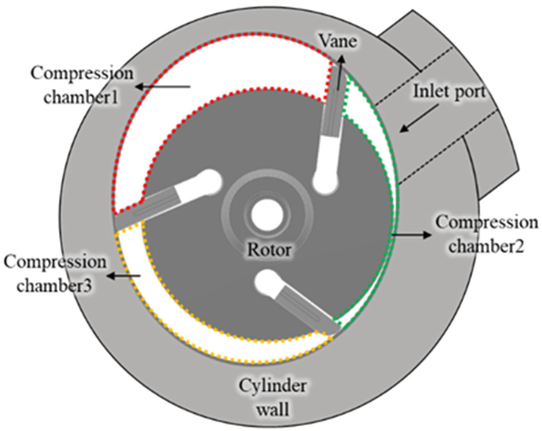
A rotary-vane compressor in Figure 1 is a mechanical device that compresses a refrigerant gas by maintaining contact between the cylinder wall and the vanes that move radially in a reciprocating motion [1]. When the rotor is stationary, the vanes are located in slots inside the rotor. As the rotor rotates, the vanes slide along the slots toward the cylinder wall due to centrifugal forces and come into contact with the inner wall of the cylinder, forming compression chambers enclosed by a vane-rotor-vane-wall configuration. Refrigerant gas is sucked through the inlet port to the compression chamber and compressed due to the change in the volume of the chamber as the rotor rotates, and the compressed gas is discharged through an outlet port. However, if the centrifugal force and the back-pressure pocket force acting on the vane are insufficient, the vane does not contact the inner wall of the cylinder, and the compression chamber is not sealed, allowing refrigerant to leak. This phenomenon is called the “jumping phenomenon” in a rotary-vane compressor and it not only reduces the efficiency of the compressor but also leads to vibration and noise from the unstable motion of the vane. Excessive contact between the vane and the inner wall of the cylinder causes critical wear on both the vane and the cylindrical wall and reduces the lifespan of the compressor.
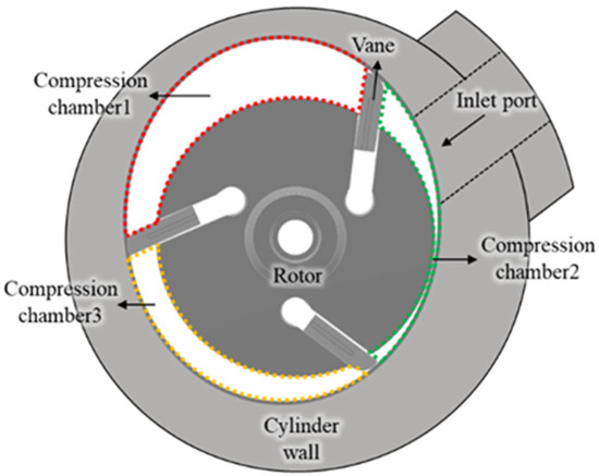
Figure 1.
Cross-section of a rotary vane compressor.
The dynamic motion and frictional loss of vanes in a rotary-vane compressor have been subjected to multiple investigations. Yoshimura and Wang [2,3] studied the effects of surface roughness on the lubrication characteristics of the vane rotating with thin clearance or in contact with the cylinder wall. Teh and Ooi [4,5] and Shakya and Ooi [6] developed a method to calculate frictional loss and leakage of the compressors and experimentally validated their method. Hawaj and Dai [7,8] proposed an analytical model for a rotary-vane compressor with inter-cell leakage due to variations in pressure and temperature. Choo and Ooi [9,10] calculated and compared the efficiency of a rotary-vane compressor with one vane and another with three vanes. Tan and Ooi [11,12] developed a method to analyze the lubrication of journal bearings inside a compressor and the frictional loss due to a valve. Liu et al. [13] conducted a lubrication analysis considering elasto-hydrodynamic lubrication (EHL) of the journal-thrust bearing system to investigate the shaft behavior in a rotary compressor and the effects of shaft deformation and high-pressure environments on wear and lubrication performance. Sarip and Li [14,15] developed a method to calculate frictional loss at the side and tip of a vane using the frictional coefficient and the contact force, but they did not consider fluid lubrication. Li et al. [16] studied the effect of groove design in a rolling piston compressor on lubrication condition, friction loss, and wear between the vane and slot, and proposed an optimized design. Fang et al., Geng et al., and Wen et al. [17,18,19] analyzed the linear and rotational motion of the vane considering EHL and conducted research to enhance lubrication and wear performance. Hu and Bianchi [20,21,22,23] calculated the frictional loss at the side and tip of the vane considering fluid lubrication, obtained the frictional coefficients from experiments, and applied them differently at the tip and side of the vane. They also developed equations of the motion of the vane in three degrees of freedom. Zhou et al. [24] described a method of analyzing the three-degrees-of-freedom behavior of the vane and validated it using measured wear patterns on the side of the vane. However, most prior studies did not simultaneously analyze all lubricated surfaces of the vane or consider the dynamic motion of the vane in six degrees of freedom and used a one-dimensional Reynolds equation for lubrication analysis.
In this paper, we describe a new approach to investigating the dynamic motion of a vane in six degrees of freedom and its effect on wear in a rotary-vane compressor considering fluid lubrication. We applied the Poisson equation to a compression chamber with adiabatic conditions to calculate the gas pressure and the gas force acting on the vane. Considering the tilting of the vane and the change of clearance between the vane and the slot and between the vane and the inner wall of the cylinder, we modified a Reynolds equation and used the finite element method to calculate pressure and shear stress in the lubrication area as well as the fluid-reaction force and friction force acting on the vane. We also derived and solved equations for the motion of the vane with six degrees of freedom for gas, centrifugal, inertial, Coriolis, contact, and fluid-reaction forces. We solved these equations using the finite difference method to determine the dynamic motion of the vane and the contact forces between the vane and the inner wall of the cylinder and between the vane and the slot of the rotor. Finally, we validated the proposed method by comparing the simulated dynamic motion of the vane and contact force with the measured wear patterns on the vane and the inner wall of the cylinder.
2. Method of Analysis
2.1. A Rotary-Vane Compressor
The rotary-vane compressor used in this study had three vanes in contact with the cylinder wall, forming three compression chambers. Figure 2 shows the intermediate pocket, discharge pocket, and discharge port of the rotary-vane compressor. Two intermediate pockets and discharge pockets were located symmetrically at the top and bottom of the rotor. They were connected to the rear of the vanes and recirculated some of the compressed gas from the compression chamber to the rear of the vane, which pushed the vane toward the cylinder wall. The pressure in the intermediate pocket was approximated as the average of the inlet and discharge pressures, while the pressure in the discharge pocket was equated to the discharge pressure. The refrigerant gas was sucked through the inlet port, compressed through counterclockwise rotation of the rotor, and discharged as a high-pressure gas through the discharge port.
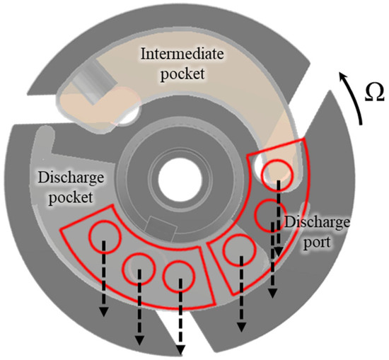
Figure 2.
Intermediate and discharge pockets of the rotary vane compressor.
Table 1 lists the typical operating conditions of the rotary-vane compressor for home appliances, which uses R134a gas as a refrigerant. We assumed that the pressures in the intermediate and discharge pockets were constant, and that the pressure changes between these pockets changed linearly with respect to the rotating angle. We also assumed a maximum clearance of 18 μm between the vane and the inner wall of the cylinder and a maximum clearance of 9 μm between the vane and rotor slot.

Table 1.
Operating conditions.
2.2. Gas Pressure of the Compression Chamber
The gas pressure of the compression chamber can be calculated using Equation (1) with the assumption of no gas leakage and an adiabatic process [25]:
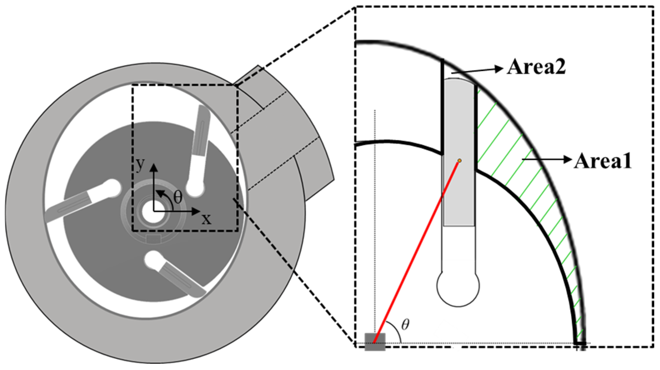
where Pc and Pi are the pressures in the compression chamber and the intake gas pressure, respectively. The variables ρc, ρi, Vc, Vi, and k are the gas density in the compression chamber, inlet gas density, chamber volume, inlet chamber volume before the compression process, and specific heat ratio of the gas, respectively. Figure 3 shows how we calculated the chamber volume. Area1 is the cross-sectional area corresponding to the main compression chamber, and Area2 is the cross-sectional area between the vane tip and the cylinder wall. The cylinder wall is composed of four quarters of four different ellipses and the vane tip has the shape of a circular arc. We included Area2 as well as Area1 to accurately calculate the chamber volume at each rotating angle of the rotor, as shown in Figure 3.
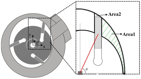
Figure 3.
Calculation of the chamber volume considering the vane tip.
2.3. Pressure and Shear Stress Due to Fluid Lubrication
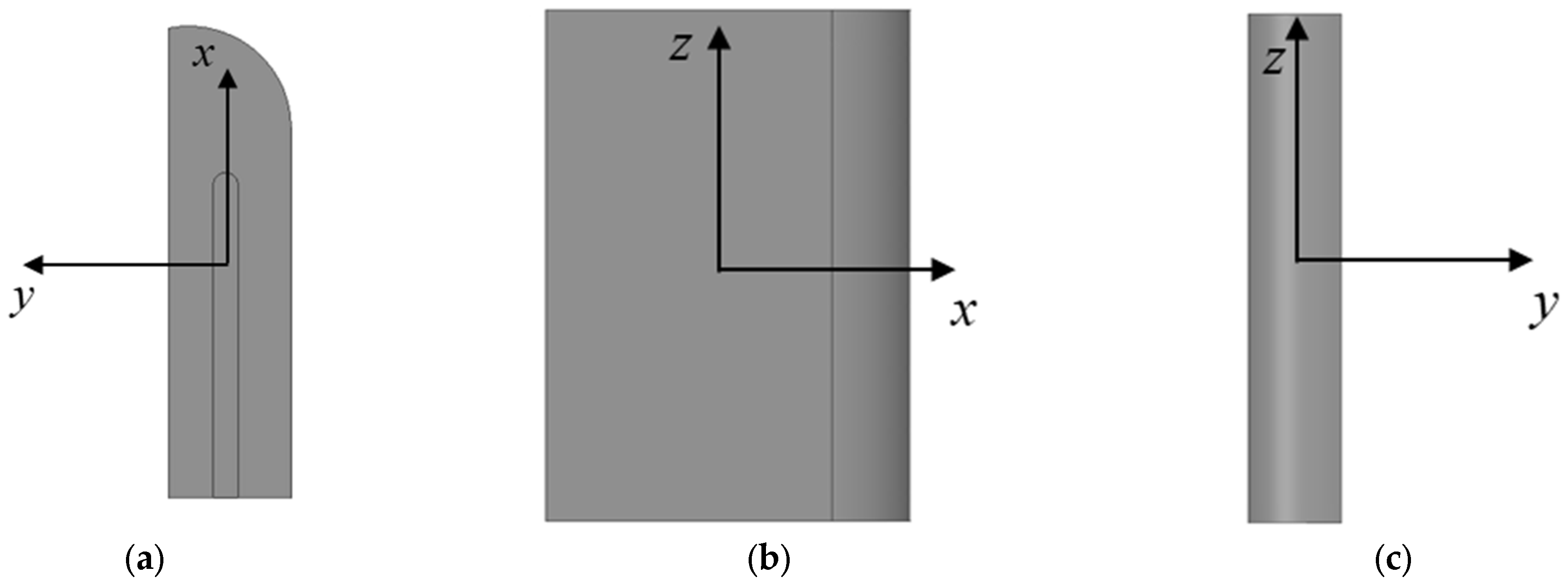
The rotary-vane compressor had a lubricating-fluid supply system to minimize mechanical friction. Assuming sufficient lubricating fluid, five lubricated surfaces were considered: top, bottom, and left- and right-side surfaces between the vane and the rotor slot and the front surface between the vane and the cylinder wall. We used the Reynolds equation for each surface to calculate the pressure and the shear stress, including the rotation of the rotor and the protruding motion of the vane. Figure 4 depicts the flow direction of the lubricating fluid on the top, side, and front surfaces of the vane. On the top and bottom surfaces, the lubricating fluid flows due to the rotating speed of the rotor and the protruding speed of the vane. The corresponding Reynolds equation can be expressed as Equation (2) [26]. On the side surfaces, the lubricating fluid flows along the protruding and axial directions of the vane, and the corresponding Reynolds equation can be written as Equation (3). On the front surface, it flows along the direction of the rotation of the rotor and the axial direction, and the corresponding Reynolds equation for the laminar flow can be written as Equation (4).
where h, p, μ, Ṽx, Ṽy, Ṽz, and t are the clearance, pressure, viscosity of the lubricating fluid, average protruding velocity of the vane, average velocity of the rotating direction, average velocity along the z-axis direction, and time, respectively. The finite element equations of the Reynolds equation are derived as follows:
where A, N, and Pe are the element area, shape function matrix, and local nodal pressure vector of the element, respectively. The finite element equations derived from the five lubricated surfaces can be combined into a global matrix equation to ensure continuity of pressure and flow along the connecting lines of the five surfaces:
where [K], {P}, and {F} are the global stiffness matrix, global nodal pressure vector, and global nodal force vector, respectively. The pressure of the compression chamber, intermediate pocket, discharge pocket, discharge port, and inlet port are applied to the corresponding area of the finite element model of the vane as boundary conditions, and the boundary condition changes as the rotor rotates because the protruding length of the vane and the gas pressure change with the rotating angle of the rotor. Figure 5 depicts the external boundary conditions of the vane at the rotating angle where the discharge port does not overlap. At the rotating angle where the discharge port overlaps, discharge pressure was added to the top and bottom surfaces of the vane as another boundary condition. After the pressure was calculated from Equation (8), the fluid-reaction force was calculated using Equation (9), and the shear force was calculated using Equation (10).

Figure 4.
(a) Top, (b) side, and (c) front views of the vane.
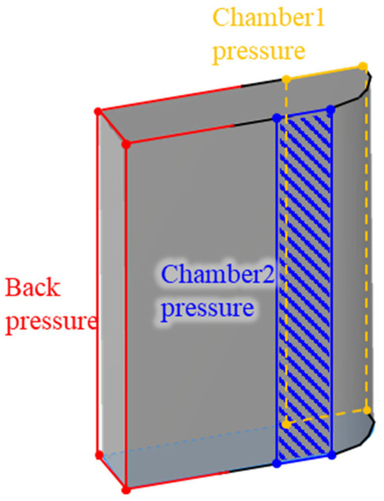
Figure 5.
Boundaries of the vane.
2.4. Motion of the Vane in Six Degrees of Freedom
Figure 6 shows a free-body diagram of the vane with the forces applied in each direction. The x, y, and z directions correspond to the protruding direction of the vane toward the cylinder wall, the motion of the vane toward the side surface of the slot, and the up-and-down axial motion of the vane. The vane exhibited a tilting motion with respect to the θx, θy, and θz directions due to the unbalanced external forces. In Figure 6b, Fb, FCor, and Fcen are the back-pressure pocket force, Coriolis force, and centrifugal force, respectively. Pside1, Pside2, and Pfront,x are the respective x-components of the fluid pressures on the left side, right side, and front surface of the vane. τside1,x, τside2,x, and τfront,x are the x-components of the shear forces on the left side, right side, and front surface of the vane, respectively. Similar notations are used in Figure 6c,d.
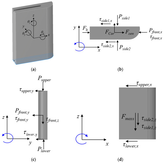
Figure 6.
(a) Free-body diagram of the vane and external forces on the (b) top, (c) front, and (d) side.
As shown in Equations (11)–(16), we derived the equations of the motion of the rigid vane with respect to six degrees of freedom by considering the forces and moments acting on the vane with respect to its mass center. They are the Euler equations which linearize the nonlinear terms of the angular velocity by small angle approximation [27]:
where Fmass, Ffluid, Fshear, Fcontact, Mfluid, Mshear, and Mcontact are the weight force, fluid-reaction force, shear, and contact forces, and their respective moments. Additionally, , , , Ixx, Iyy, Izz, , , , , , , and Ω are accelerations, mass moments of inertia, angular velocities, angular accelerations, and rotor speed, respectively. In Equation (11), Fshear,x and Ffluid,x are the x-components of the shear force and fluid-reaction force, respectively. The expression for Fshear,x can be written as
where τfront,x, τside1,x, τside2,x, τupper,x, and τlower,x are the x-directional shear force acting on the front, side1, side2, upper, and lower surfaces of the vane, respectively. Equations (11) and (12) were derived using the same method. In Equation (13), Mfluid,θx and Mshear,θx are the moments due to the fluid-reaction force and shear force acting along the θx direction, respectively. The expression for Mshear,θx is
where τfront,y, τupper,y, τlower,y, τside1,z, τside2,z, zF, lt and lh are the y-directional shear force acting on the front, upper, and lower surfaces of the vane; the z-directional shear force acting on the side1 and side2 surfaces of the vane; the z-directional distance of each node from the mass center; and the thickness and height of the vane, respectively. Equations (15) and (16) were derived using the same method. The centrifugal force can be written as
where lout is the distance from the center of the rotor to the mass center of the vane. The Coriolis force can be determined from the protruding velocity of the vane and the rotating speed:
where u is the protruding velocity of the vane.
We used the central difference method to solve the equations of motion numerically. When the vane contacted the inner wall of the cylinder, we applied the contact force and moment in Equations (21) and (22) to analyze the dynamic motion of the vane accurately. To determine the contact clearance, we used a method proposed by Priest et al. [28]. We measured the surface roughness of the vane, cylinder wall, and rotor slot, assuming that the vane contacted the cylinder wall or the rotor slot when the clearance reached 4 μm. If the clearance between the vane and the cylinder wall exceeded 20 μm after the vane moved along the negative x-direction, we assumed that no fluid lubrication existed between the vane and the cylinder wall, and that a jumping phenomenon occurred.
2.5. Numerical Algorithm
Figure 7 shows a diagram of the numerical algorithm used to investigate the dynamic motion of the vane. First, we set initial parameters and conditions and calculated the chamber volume and pressure using Equation (1). The operating conditions were then used to calculate the centrifugal, Coriolis, gas, and back-pocket forces. Next, we applied the bisection method to solve the difference equations of the motion of the vane in six degrees of freedom. We set the time step of the equations of motion about 5 × 10⁻⁶ s. For example, when calculating the axial (z-direction) displacement of the vane, the maximum and minimum possible clearances at the center of the lower surface of the vane were calculated and denoted as hmax and hmin, respectively. We calculated the fluid pressure in the lubricating film by solving the Reynolds equation using Equation (8). The fluid-reaction force can be calculated by multiplying the fluid pressure with the lubrication area. To solve the difference equation of the motion in Equation (13), we calculated the numerical error, Ferror,z, which is defined as the left side of Equation (13) minus the right side ( The numerical errors corresponding to hmax and hmin were Fmax and Fmin, respectively. At this stage, we assumed that the vane did not make contact and did not include the contact force. If Fmax and Fmin had opposite signs, the solution of the axial displacement was between hmax and hmin, and the intermediate clearance hmid was calculated. The corresponding error Fmid was evaluated, and hmin and hmax were reset based on a comparison of signs between Fmin and Fmid. This iteration continued until Ferror,z converged at less than 1 × 10⁻⁶ N. If Fmax and Fmin had the same sign, convergent clearance had not occurred, requiring contact force for convergence of the equation of the motion. The contact surface (upper or lower) was determined by the sign of these values. When contact occurred, the axial (z-direction) velocity was set to zero, and the contact force at the next step was calculated using Equation (21). The same numerical procedure was applied to Equations (11) and (12) to calculate the x- and y-direction motions of the vane, and Equations (14)–(16) were used to calculate the tilting angles (θx, θy, θz), respectively. A convergent solution to the equation of the motion of the vane was calculated through this numerical process. All simulations in this study were performed by a personal computer with Intel Core i7-8700 CPU (3.2 GHz), 64 GB RAM, NVIDIA GTX 1050 Ti GPU, and Windows 10 operating system, and it took approximately 5 h to analyze the dynamic and lubrication behavior of the vane for one revolution of the rotor.
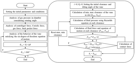
Figure 7.
Numerical algorithm of dynamic behavior of the vane.
3. Simulation Results
3.1. Simulated Pressure of the Compression Chamber
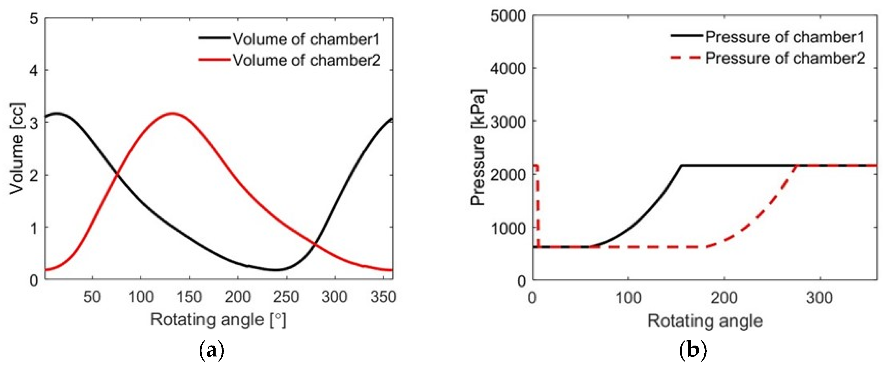
We calculated the volume and gas pressure of the compression chamber at each rotating angle using the method detailed in Section 2.2 and Equation (1). The left and right compression chambers were designated chamber1 and chamber2, respectively, as shown in Figure 1. Figure 8 depicts the simulated volume and gas pressure in chamber1 and chamber2 as the vane rotated through 360°. As shown in Figure 8a, the maximum and minimum volumes of chamber1 occurred at 15° and 245°, respectively. In Figure 8b, the simulated pressure of chamber1 shows that compression began at approximately 60° and discharge at 150°. The inlet pressure remained constant until the rotor rotated by 60° because the refrigerant flowed into the compression chamber through the inlet port.
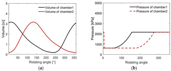
Figure 8.
(a) Simulated volume and (b) pressure in the chambers.
3.2. Simulated Pressure of the Fluid Lubricant
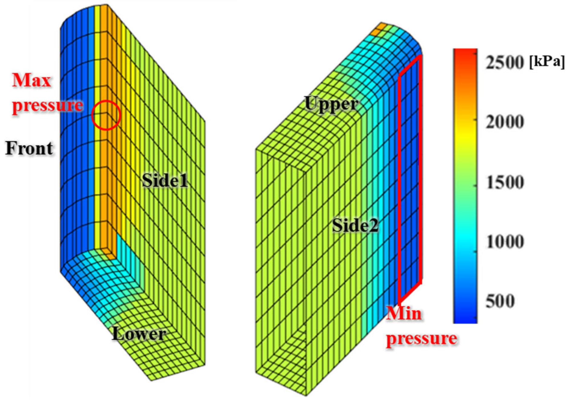
The finite element model of the lubricating fluid on the vane surface was constructed with 22 nodes in the x-direction and 10 nodes in both the y- and z-directions. The average grid size of the finite element model is approximately 1.5 × 10⁻⁷ m2. We analyzed the fluid pressure of the vane using the gas pressure around the vane and back pressure as boundary conditions, as shown in Section 2.3 and Figure 5. Figure 9 displays the pressure distribution of the vane at a rotating angle of 150°. At this position, the pressures of chamber1 and chamber2 were calculated to be 2118.1 kPa and 626.6 kPa, respectively, and the back pressure corresponded with the intermediate pocket pressure of 1687 kPa. The maximum pressure on the vane was 2200 kPa on the front surface, where the clearance was minimal due to the shape of the vane tip and cylinder wall. The calculated pressure distributions on the upper and lower surfaces of the vane were identical. The minimum pressure acting on the vane was 626.6 kPa at the boundary adjacent to chamber2.

Figure 9.
Pressure distribution of the vane.
3.3. Simulated Motion of the Vane in Six Degrees of Freedom and Contact Force
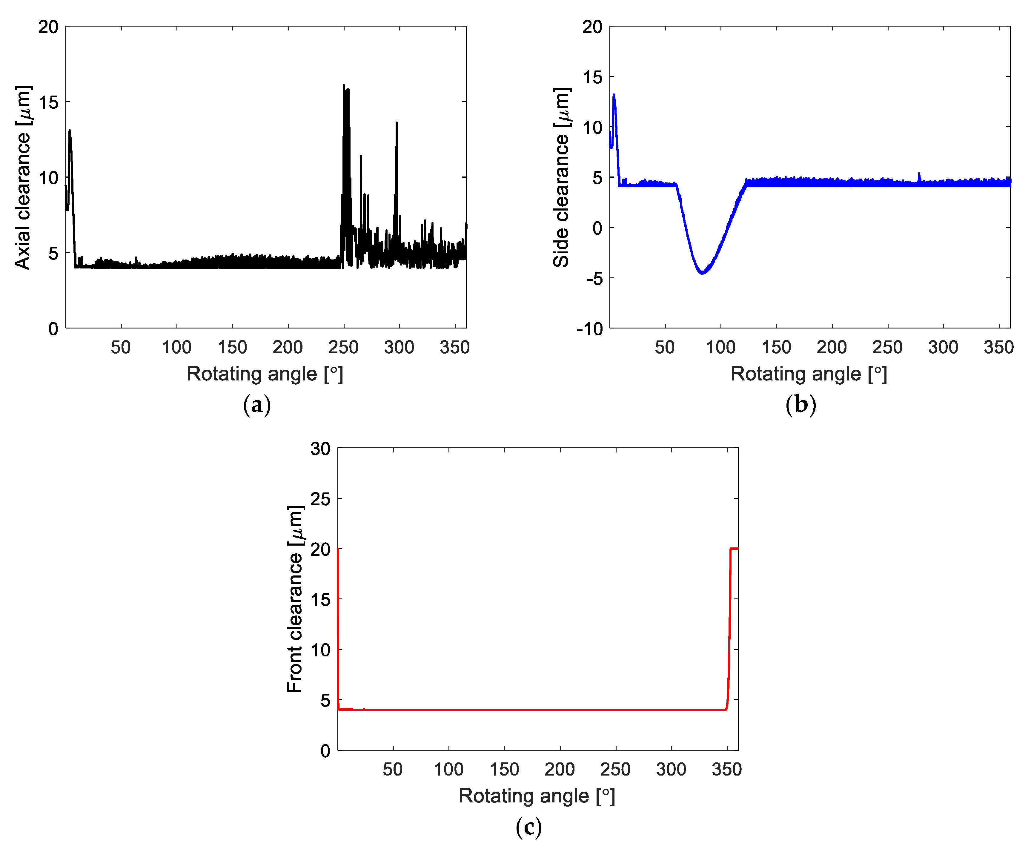
We then analyzed the dynamic motion of the vane. Figure 10 depicts the variations in axial clearance of the center of the bottom surface, the side clearance of the center of the right-side surface, and the front clearance of the center of the front surface of the vane, respectively. Figure 10a shows the simulated axial clearance and the unstable motion during the transient period due to the rapid pressure change in compression chamber2 in Figure 8b, which quickly stabilized to the equilibrium position, primarily due to its weight. After rotating 247°, the axial clearance fluctuated due to the pressure changes as the vane passed through the discharge port at the position shown in Figure 2. The axial clearance then gradually stabilized. Figure 10b shows the simulated side clearance with unstable motion during the transient period and the rapid stabilization. After rotating 50°, the side clearance became negative, indicating that the mass center of the vane protruded out of the slot and tilted along the negative θz direction, reaching a minimum value of approximately −5 μm. The vane then moved back to the slot, with a minimum side clearance of 4 μm. In the simulated front clearance shown in Figure 10c, the front surface of the vane contacted the cylinder wall rapidly and formed stable compression chambers. The front clearance increased rapidly at a rotation angle of 350° because the gas pressure in the compression chamber exceeded the back-pocket pressure.

Figure 10.
(a) Variations of axial clearance, (b) side clearance, and (c) front clearance of the vane.
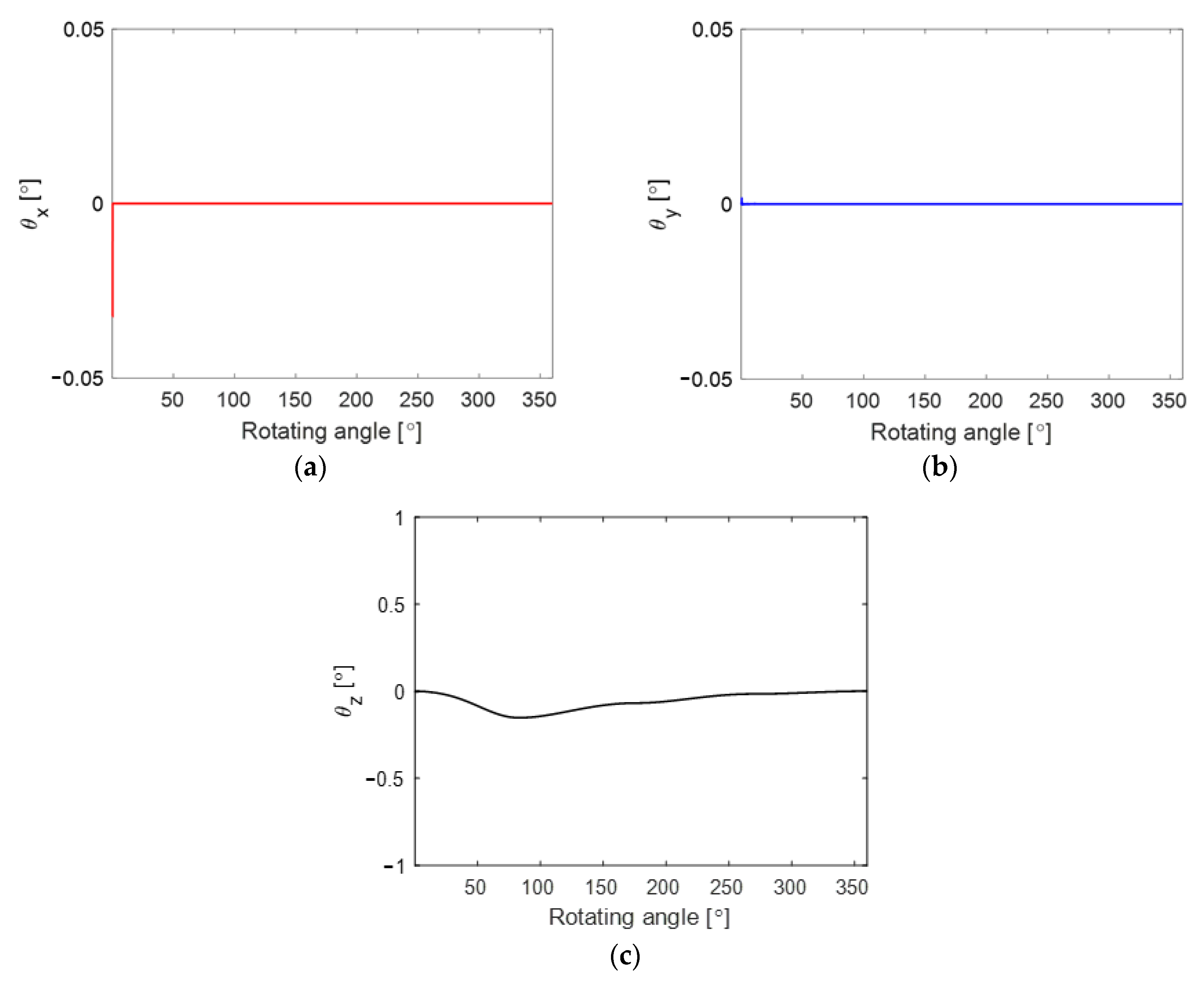
Figure 11 shows the simulated tilting angles θx, θy, and θz of the vane according to the rotating angle of the rotor. Figure 11a,b show the simulated θx and θy, which exhibited almost no tilting motion along the x- and y-directions except for the initial rotating angles. Figure 11c shows the simulated θz decreasing to approximately −0.2° as the rotating angle increased. The rotating angle at which θz reached its minimum value corresponded to the rotating angle where the vane maximally protruded from the slot and the vane contacted the right side of the rotor slot.
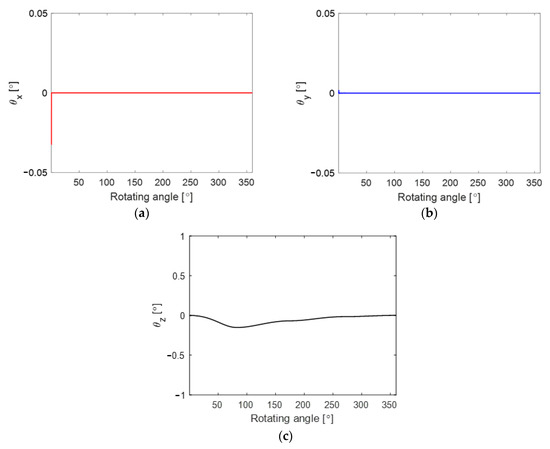
Figure 11.
Variations of (a) θx, (b) θy, and (c) θz of the vane.
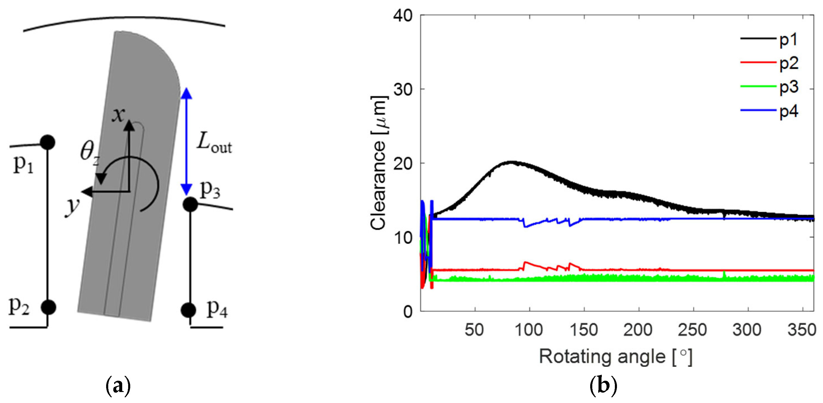
Figure 12a shows an illustration of a top view of the vane and the four corners on the left and right sides of the rotor slot. Figure 11b shows the simulated clearance at points p1, p2, p3, and p4 according to the rotating angle of the rotor. As shown in Figure 11a–c, the vane tilted along the negative θz direction for most rotating angles. Figure 11b indicates that p2 and p3 were the contact locations between the vane and the slot. The vane contacted p2 only during the transient period and p3 for most rotating angles. The clearance of p1 increased to 20 μm because the vane protruded with the negative tilting angle of θz until the rotor rotated 100° and then decreased up to 14 μm.
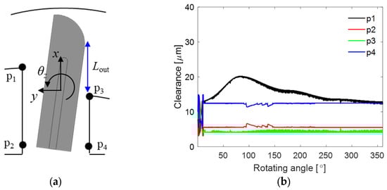
Figure 12.
(a) Top view of the vane and (b) simulated clearance at each point.
Figure 13 shows the simulated contact force of the bottom, side, and front surfaces of the vane. Figure 13a shows that the contact force on the bottom surface of the vane is relatively large at regions 1 and 2. The large contact force in region 1 is due to the initial position and velocity of the vane, causing contact at the bottom surface. In region 2, unstable motion occurred as the top surface of the vane passed through the discharge port, resulting in a large contact force. Figure 13b shows the simulated side-contact forces at corners p2 and p3 in Figure 12b. No contact occurred at corners p1 and p4. During the transient period, the vane made contact at corner p2 twice, and for most of the rotating angles, the vane was in contact with corner p3. Figure 13c shows the simulated contact force between the front surface of the vane and the cylinder wall according to rotating angle in three regions. Region 1 is the transient phase during which the contact force rapidly increased and then decreased because the vane contacted the cylinder wall rapidly at high speed. In region 2, the contact force increased gradually, the vane maximally protruded, and a large contact force originated from the strong centrifugal force. In region 3, the contact force was relatively large, at approximately 200°, and this region corresponds to the transition period of the back pressure from the intermediate pocket to the discharge pocket at the rear surface of the vane, resulting in increased pushing force. As the pressure in the discharge pocket decreased, the contact force gradually converged to zero.
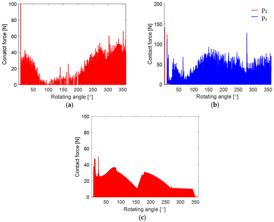
Figure 13.
Simulated contact force at (a) the bottom, (b) side, and (c) front of the vane.
4. Experimental Validation
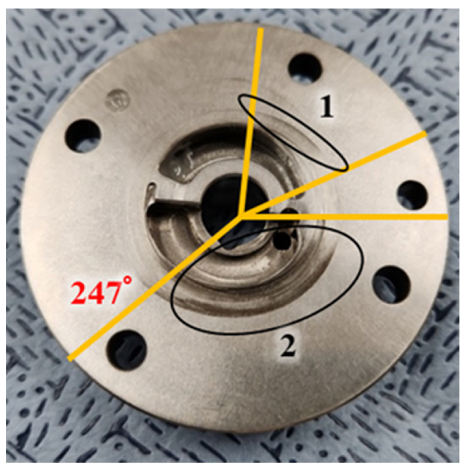
To validate the proposed numerical method, we operated the rotary-vane compressor for 800 h under the same simulation conditions. During the operation, the temperature and pressure of the inlet gas and the discharge gas were kept constant. The wear patterns of the vane, the bottom thrust bearing, and the cylinder wall were measured, and they were compared with the simulated contact force with the assumption that the wear occurs due to the friction force proportional to the contact force. Figure 14 shows the wear pattern of the bottom thrust bearing, which faces the bottom surface of the vane. The wear pattern is visible in regions 1 and 2. The simulated contact force on the bottom surface of the vane in Figure 13a was compared with the measured wear patterns in Figure 14. The simulated unstable axial clearance in Figure 10a, which began at 247°, where the vane passed the discharge port, matched a distinct wear pattern at the same rotating angle. The simulated large contact force on the bottom surface of the vane in Figure 13a in regions 1 and 2 matched that in the regions with wear patterns, as observed in Figure 14.

Figure 14.
Lower bearing wear pattern.
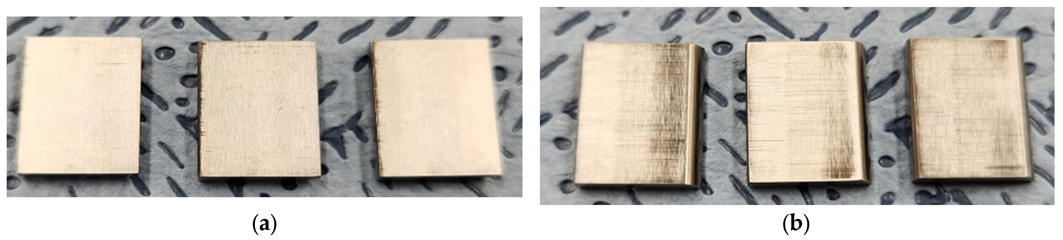
Figure 15 depicts the wear patterns on the left and right sides of the vane. The compressor operated with three vanes rotating simultaneously, and the wear patterns on all three vanes are similar. On the left side of the vane, the wear pattern was visible only at the rear tip of the vane, matching the contact of corner p2 in Figure 12b. The distinct wear patterns on the right side matched the simulated contact of corner p3 at most rotating angles in Figure 12b and the simulated contact force of the side of the vane at corner p3 in Figure 13b. This indicates significant contact on the right side, and the wear patterns were affected by the protruding length of the vane.
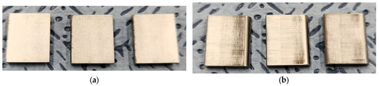
Figure 15.
(a) Left-side and (b) right-side wear patterns of the vane.
Figure 16 shows the wear patterns on the inner wall of the cylinder as measured using a Prisomo three-dimensional optical-surface-measuring machine (Zeiss). The maximum wear amount was approximately 2 μm. The three vanes scraped the inner wall of the cylinder as they rotated counterclockwise, and significant wear was measured as the vane passed through 0°, 90°, and 250°. This closely matched the simulated contact force between the front surface of the vane and the inner wall of the cylinder in Figure 13c, which shows large contact forces near 0°, 90°, and 250°. This confirmed that the measured wear pattern followed the simulated contact force. However, a slight difference was evident between the rotating angle of the maximum contact force and that of the maximum wear location. This may have arisen from the assumption that the pressure of the back-pressure pocket is constant in simulations, even though the pressure of the back-pressure pocket slightly changes due to the pressure variation of the discharge port or the volume change of the slot at the rear part of the vane as the vane moves along the slot.
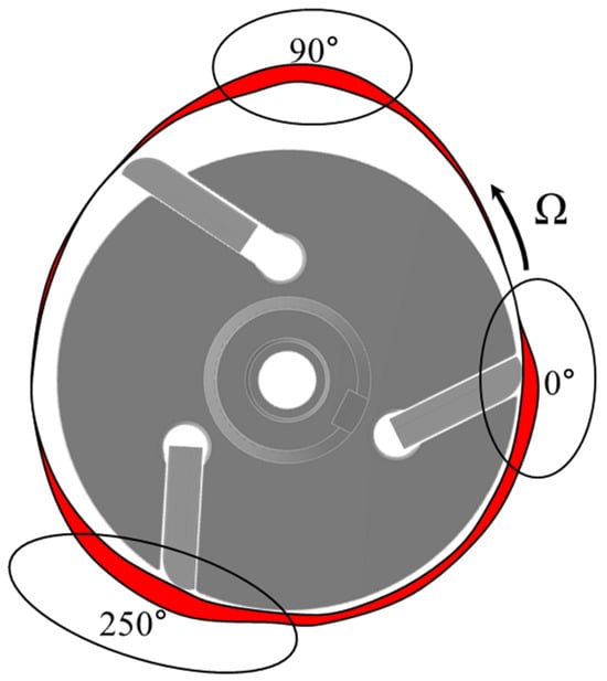
Figure 16.
Wear pattern of the inner wall of the cylinder.
5. Conclusions
This paper investigated the dynamic motion of a vane in six degrees of freedom and its effect on wear in a rotary-vane compressor considering fluid lubrication. We solved the Poisson equation assuming adiabatic conditions when calculating the gas pressure in the compression chamber and the gas force acting on the vane. We solved the Reynolds equation in the lubrication area between the vane and the cylinder and between the vane and the slot using the finite element method to calculate pressure and shear stress in the lubrication area and the fluid-reaction and friction forces acting on the vane. We also derived and solved equations for the motion of the vane in six degrees of freedom considering gas, centrifugal, inertial, Coriolis, contact, and fluid-reaction forces. We solved these equations using the finite difference method to determine the dynamic motion of the vane. Finally, we validated the proposed method by comparing the simulated dynamic motion of the vane and contact force with the measured wear patterns on the vane and the inner wall of the cylinder. We did not calculate the wear directly but we calculated the contact force with the assumption that the wear occurs due to the friction force proportional to the contact force. Direct calculation of the wear between vane and cylinder will be one of the future research topics. The proposed method should contribute to future investigations of the design and operating conditions of rotary-vane compressors and should help with the development of a robust and efficient rotary-vane compressor with less vibration and noise.
Author Contributions
Conceptualization, G.J.; methodology, G.H.; software, G.H. and Y.P.; validation, G.H.; formal analysis, G.H. and Y.P.; investigation, G.H.; resources, G.H.; data curation, G.H.; writing—original draft preparation, G.H.; writing—review and editing, G.J.; visualization, G.H and Y.P.; supervision, G.J.; project administration, G.J.; funding acquisition, G.J. All authors have read and agreed to the published version of the manuscript.
Funding
This work was partially supported by a Korea Energy Technology Evaluation and Planning (KETEP) grant funded by the Ministry of Trade, Industry, and Energy (MOTIE) (RS-2022-KP002839, Development of silicon carbide composite material technology with improved surface lubricity, 2025).
Data Availability Statement
Data are contained within the article.
Conflicts of Interest
The authors declare no conflicts of interest.
Nomenclature
| pocket force | |
| centrifugal force | |
| contact force | |
| Coriolis force | |
| numerical error in z-direction | |
| weight force | |
| numerical error at maximum clearance | |
| numerical error at intermediate clearance | |
| numerical error at minimum clearance | |
| heat capacity ratio | |
| height of vane | |
| distance from rotor center to vane center | |
| thickness of vane | |
| contact torque | |
| gas pressure in the chamber | |
| discharge and intermediate pocket pressure | |
| inlet and discharge gas pressure | |
| pressure acting on the side1, side2, front, upper, and lower surface | |
| gas density in the chamber | |
| inlet gas density | |
| inlet gas temperature | |
| shear force acting on the side1, side2, front, upper, and lower surface | |
| volume of the chamber | |
| inlet gas volume | |
| distance from mass center | |
| Greek symbols | |
| rotating speed of rotor | |
References
- Aw, K.; Ooi, K. A review on sliding vane and rolling pistion compressors. Machines 2021, 9, 125. [Google Scholar] [CrossRef]
- Yoshimura, T.; Ono, K.; Inagaki, K.; Kotsuka, H.; Korenaga, A. Analysis of lubricating characteristics of rotary compressors for domestic refrigerators. Trans. ASME 1999, 121, 510–516. [Google Scholar] [CrossRef]
- Wang, F.; Sun, Z.; Fiebig, W.; Xu, B.; Stelson, K. Lubrication and fluid film study on the vane tip in a vane pump hydraulic transmission considering a fluid and structure interaction. J. Tribol. 2021, 143, 121803. [Google Scholar] [CrossRef]
- Teh, Y.; Ooi, K. Theoretical study of a novel refrigeration compressor—Part I: Design of the revolving vane (RV) compressor and its frictional losses. Int. J. Refrig. 2009, 32, 1092–1102. [Google Scholar] [CrossRef]
- Teh, Y.; Ooi, K. Experimental study of the revolving vane (RV) compressor. Appl. Therm. Eng. 2009, 29, 3235–3245. [Google Scholar] [CrossRef]
- Shakya, P.; Ooi, K. Introduction to coupled vane compressor: Mathematical modelling with validation. Int. J. Refrig. 2020, 117, 23–32. [Google Scholar] [CrossRef]
- Hawaj, O. Theoretical modeling of sliding vane compressor with leakage. Int. J. Refrig. 2009, 32, 1555–1562. [Google Scholar] [CrossRef]
- Dai, Y.; Zhu, H.; Bianchi, G.; Rane, S.; Ye, F. Numerical investigation on flow characteristics and working performance in oil-injected sliding vane rotary compressors. Int. J. Refrig. 2025, 171, 202–216. [Google Scholar] [CrossRef]
- Choo, W.; Ooi, K. Analysis of the novel multi-vane Revolving Vane compressor—Theoretical modelling and experimental investigations. Int. J. Refrig. 2021, 131, 592–603. [Google Scholar] [CrossRef]
- Choo, W.; Ooi, K. Analysis of the novel multi-vane revolving vane compressor investigation of vane chattering phenomenon through instantaneous working chamber pressure measurements. Int. J. Refrig. 2022, 134, 207–218. [Google Scholar] [CrossRef]
- Tan, K.; Ooi, K. Journal bearings design for a novel revolving vane compressor. Int. J. Refrig. 2011, 34, 94–104. [Google Scholar] [CrossRef]
- Tan, K.; Ooi, K. A novel revolving vane compressor with a fixed-vane. Int. J. Refrig. 2011, 34, 1980–1988. [Google Scholar] [CrossRef]
- Liu, R.; Jing, L.; Meng, X.; Lyu, B. Mixed elastohydrodynamic analysis of a coupled journal-thrust bearing system in a rotary compressor under high ambient pressure. Tribol. Int. 2021, 159, 106943. [Google Scholar] [CrossRef]
- Sarip, A.; Musa, M. Friction analysis on vane of an existing and of a novel multi vane rotary compressor. Appl. Mech. Mater. 2013, 284–287, 763–767. [Google Scholar] [CrossRef]
- Li, L.; Zhao, Y.; Guo, B.; Shu, P.; Shen, J.; He, S. Wrap of cylinder and its effect on main features of rotary vane compressor for automobile air conditioning system. Int. J. Refrig. 2003, 26, 566–574. [Google Scholar] [CrossRef]
- Li, R.; Jing, L.; Meng, X.; Lui, Z.; Zhang, R. Numerical analysis of vane–slot friction pair in a rolling piston compressor considering deformation and groove design. Tribol. Int. 2021, 162, 107124. [Google Scholar] [CrossRef]
- Fang, C.; Meng, X.; Xie, Y. A Piston tribodynamic model with deterministic consideration of skirt surface grooves. Tribol. Int. 2017, 110, 232–251. [Google Scholar] [CrossRef]
- Geng, K.; Geng, A.; Wang, X.; Zheng, X.; Wei, W.; Zhao, T.; Lei, Y.; He, Y. Frictional characteristics of the vane–chute pair in a rolling piston compressor based on the second-order motion. Tribol. Int. 2019, 133, 111–125. [Google Scholar] [CrossRef]
- Wen, C.; Liu, Z.; Wen, X.; Gao, K.; Guan, J.; Bai, P.; Meng, Y.; Tian, Y. Dynamic modeling and characteristics analysis of sliding vane in a high-speed rotary compressor considering groove distribution and multi-body coupling. Tribol. Int. 2024, 194, 109505. [Google Scholar] [CrossRef]
- Hu, X.; Qu, Z.; Yang, X.; Sun, J. Theoretical study on frictional losses of a novel automotive swing vane compressor. Int. J. Refrig. 2013, 36, 758–767. [Google Scholar] [CrossRef]
- Bianchi, G.; Cipollone, R. Friction power modeling and measurements in sliding vane rotary compressor. Appl. Therm. Eng. 2015, 84, 276–285. [Google Scholar] [CrossRef]
- Bianchi, G.; Cipollone, R. Theoretical modeling and experimental investigations for the improvement of the mechanical efficiency in sliding vane rotary compressor. Appl. Energy 2015, 142, 95–107. [Google Scholar] [CrossRef]
- Yang, X.; Dong, C.; Qu, Z. Design and dynamic analysis of a novel double-swing vane compressor for electric vehicle air conditioning systems. Int. J. Refrig. 2017, 76, 52–62. [Google Scholar] [CrossRef]
- Zhou, H.; Qu, Z.; Yang, H.; Yu, B. Dynamic model and numerical simulation for synchronal rotary compressor. J. Fluids Eng. 2009, 131, 041102. [Google Scholar] [CrossRef]
- Nederstigt, P.; Pecnik, R. Generalised isentropic relations in thermodynamics. Energies 2023, 16, 2281. [Google Scholar] [CrossRef]
- Hamrock, B. Fundamentals of Fluid Film Lubrication, 2nd ed.; McGraw-Hill: New York, NY, USA, 1994. [Google Scholar]
- Beer, F.; Johnston, E., Jr.; Cornwell, P. Vector Mechanics for Engineers Dynamics, 9th ed.; McGraw-Hill: New York, NY, USA, 2008. [Google Scholar]
- Priest, M.; Dowson, D.; Taylor, C. Predictive wear modelling of lubricated piston rings in a diesel engine. Wear 1999, 231, 89–101. [Google Scholar] [CrossRef]


Disclaimer/Publisher’s Note: The statements, opinions and data contained in all publications are solely those of the individual author(s) and contributor(s) and not of MDPI and/or the editor(s). MDPI and/or the editor(s) disclaim responsibility for any injury to people or property resulting from any ideas, methods, instructions or products referred to in the content. |
© 2025 by the authors. Licensee MDPI, Basel, Switzerland. This article is an open access article distributed under the terms and conditions of the Creative Commons Attribution (CC BY) license (https://creativecommons.org/licenses/by/4.0/).