Abstract
Gears play an important role in modern machinery and are indispensable transmission components, particularly at high speeds, where lubrication is essential for the reliability and efficiency of the gear unit. In order to study the oil coverage law and heat dissipation mechanism of high-speed rotating meshing gears by injection angle, this paper adopts the moving particle semi-implicit method to establish a high-speed rotating gear lubrication model, study the intrinsic effect of different jet angles on gear lubrication, and build a gear lubrication bench for experimental verification. Numerical simulation found that with an increase in spray angle, the gear surface coverage and heat transfer coefficient of the high-speed rotating transmission gears initially increase and then decrease. They reflect the same lubrication law characteristics. When the injection angle was 90°, the surface coverage and heat transfer coefficient values were at their greatest, resulting in the best spray lubricating effect. According to the experimental results, under the conditions of 0.5 MPa injection pressure and high-speed rotation of the transmission gear with vertical injection, the lubricant covers the largest surface area of the gear and the least power loss. Simultaneously, in our previous study, we experimentally obtained the optimal parameter conditions on the basis of which we derived. The effect of nozzle diameter on jet lubrication was investigated in a previous study, and in this article, the effect of nozzle angle and distance on gear lubrication is investigated; the optimal conditions for high-speed lubrication of gears are the incident distance of 3.5 cm, incident angle of 90°, incident diameter of 1.5 mm, and gear speed of 2000 r/min, and the lubrication effect reaches the best ideal state; reduction in oil loss due to oil injection lubrication and power loss due to different parameters of the lubrication system. Lubrication design provides a theoretical foundation for the transmission system.
1. Introduction
Lubrication is a key mechanism to reduce the wear of mechanical systems and delay component failures. It greatly affects the operation efficiency, accuracy, and life of the equipment, especially in the field of mechanical transmission, such as aerospace, shipbuilding, metallurgy, chemical industry, transportation machinery, agricultural machinery, and engineering machinery. Large devices are used in helicopters, wind power generation equipment, large machine tools, marine reducers, and other national economic construction and defense equipment. Small devices are used in cars, household appliances, watches, and other daily necessities [1,2,3]. As people pay more and more attention to the sustainable development of the economy and society, the importance of lubrication technology has become increasingly prominent. Globally, people pay more attention to the research and application of advanced lubrication technology. In particular, gear lubrication can not only reduce friction and wear, but also reduce noise, improve working conditions, and prolong gear life. Lubrication is an important means for preventing and delaying the wear of parts and other forms of failure. Lubrication technology plays a key role in the operation and maintenance of mechanical transmission devices, affecting the performance, accuracy, and life of the equipment [4,5]. Therefore, it is very important to study the optimal injection lubrication method of gears to ensure the efficient and energy-saving operation of the transmission system, which is also the focus of the industry [6,7,8,9,10]. Several scholars have studied the lubrication of transmission gears. Li and Yang’s research on high-speed wide-tooth cylindrical gears reveals the influence of gas pressure field on lubricating oil injection, and emphasizes the benefits of symmetrically distributed injection holes for efficient lubrication and cooling [11]. Seetharaman et al. proposed a model based on simplified fluid dynamics to predict the wind resistance power loss of operating gear pairs under injection lubrication. The research results quantify the influence of key system parameters and the individual contribution of each component to the total wind resistance power loss [12]. Massini Daniele et al. designed a new test bench to study the power loss caused by the rotation of a single spur gear in a free oil environment, and to study the flow field around the rotating gear. In this experiment, the Reynolds-averaged Navier-Stokes (RANS) simulation under the background of replicating the traditional eddy viscosity model was performed to achieve good consistency of all rotation speeds [13]. Based on the experimental results and computational fluid dynamics model, Nicolas Woetzel et al. studied the power loss caused by the rotation of helical gears in pure air. Sylvain Pallas and colleagues used CFD to simulate the wind-induced power loss in a spur gear, emphasizing the importance of appropriate boundary conditions for accurate prediction of flow patterns and power loss [14]. Fernandes et al. created a finite element simulation of the temperature of polymer gears to calculate the flash temperature rise during gear meshing and the temperature field of the gear body. This model can be used to calculate the temperature field of gears under oil injection lubrication, splash lubrication, or dry friction conditions [15]. Andersson compared the two different lubrication methods of jet lubrication and oil immersion lubrication through experimental tests. The experimental results showed that the heat dissipation of the tooth surface was better and the mechanical transmission efficiency was higher during the rotation process by using jet lubrication compared with oil immersion lubrication [16]. Chen Guang and Zhou Yuancong‘s simulation of high-speed gear lubrication emphasized the importance of injection angle and flow rate to improve lubrication conditions [17]. Dai used the CFD method to study the flow characteristics of the new nozzle to predict the influence of nozzle shape and size on the pressure and velocity distribution [18]. Concli et al. established a CFD model of the transmission lubrication gear, and solved the heat transfer coefficient of the tooth surface flow based on the finite element method. The heat transfer between the tooth surface and the lubricating oil was analyzed [19]. Gan proposed a numerical method that combined a mixed elastohydrodynamic lubrication model with a finite element method based on thermal analysis [20]. Subhransu Kumar Panda and Pradeep Kumar Mishra evaluated the stress components in spur gears, emphasizing the influence of pressure angle and keyway type on gear stress [21].
This study advances previous research by examining the impact of various factors, with a particular focus on different perspectives in sensitive parameters, on the lubrication of high-speed gears. It specifically compares the effects of different injection angles (60°, 75°, 90°, 105°) on gear surface coverage and tooth surface heat transfer capacity. Additionally, a test bench is constructed to investigate and validate the lubrication theory, thereby elucidating the lubrication dynamics associated with different injection angles on gears. The findings of this research facilitate the rational design of injection angles, offering a theoretical foundation for reducing lubricating oil consumption and providing theoretical support for the design of subsequent lubrication parameters.
2. Lubrication Theory of High-Speed Gears
Traditional numerical simulations often employ finite element analysis (FEA), which, although versatile, faces limitations in handling complex fluid dynamics and multiphase flows. These challenges stem from grid quality issues and computational intensity. In contrast, the Moving Particle Semi-Implicit (MPS) method, developed by Koshizuka of the University of Tokyo, offers distinct advantages for such problems. The MPS method, based on the Lagrangian approach, eliminates the need for grid generation, enhancing computational efficiency and providing a novel pathway for solving intricate incompressible fluid flow problems [22].
The MPS method conceptualizes incompressible fluids as dynamic particle systems, where each particle encapsulates fundamental physical properties, such as velocity and pressure, which evolve with particle movement. Employing the Lagrangian framework, MPS leverages inter-particle flow information and discretized fluid equations to predict subsequent particle states. Iterative computations yield comprehensive flow field characteristics, enhancing the method’s efficacy in fluid dynamics analysis.
2.1. Moving Particle Semi-Implicit Method
MPS is based on Lagrange, and the mass conservation equation and energy conservation equation under Lagrange fluid are given.
Equation of mass conservation:
Momentum conservation equation:
In the formula, is the fluid velocity vector; is the fluid density; p is pressure; is the fluid dynamic viscosity coefficient; and is the external force vector acting on the unit mass of the fluid. The left end of the equation is expressed in Lagrangian time differential form, and the convection term is included in it.
In MPS, the particles interact with the surrounding particles through the kernel function. Here we give the kernel function established by Shakibaeinia et al. [23].
In the formula, is the distance between particles; is the radius of action of particles. It can be seen from Formula (3) that when , there is no interaction between particles; particles only interact with particles within the range of their radius of action , so the kernel function has compact support characteristics. Therefore, in order to ensure the uniformity and isotropy of the distribution in the placement of adjacent particles, the appropriate value of the effective radius is 2 to 4 times the length of the initial particle distance.
According to the kernel function, the particle number density model, the gradient vector model and the Laplace model can be obtained as follows [24]:
In the formula: is the space dimension of the problem; is the particle number density constant; is the scalar value of particle physical parameters; and is the correction factor. The particle action radius of the above models does not require consistency.
2.2. Theoretical Analysis of Heat Dissipation
In transmission systems, heat dissipation primarily occurs through conduction, convection, and radiation. For moving components such as gears, heat transfer predominantly impacts adjacent parts, including bearings and shaft supports. This process can be modeled as one-dimensional heat conduction, with thermal radiation effects considered negligible due to minimal temperature fluctuations. Consequently, this study focuses on the convective heat transfer between lubricating oil and the gear surface, while disregarding secondary factors.
The intricate interaction between lubricating oil and gear teeth during operation hinders the derivation of a standardized convective heat transfer coefficient (HTC) equation, making precise calculations of convective heat transfer values challenging [25]. Current empirical equations include lubricant properties, Prandtl, and Reynolds numbers, commonly expressing HTC as follows:
In the formula [24], is the thermal conductivity of lubricating oil, and the unit is W/(m·K); is the diameter of the gear indexing circle, and the unit is m; is a Prandtl number; and is the Reynolds number. The calculation formula for the Prandtl number is as follows:
In the formula, is the density of lubricating oil, and the unit is ; is the kinematic viscosity in ; is the specific heat capacity, and the unit is ; is the thermal conductivity of lubricating oil, and the unit is W/(m·K).
The calculation formula of the Reynolds number is as follows:
In the formula, is the rotation speed of the end face, and the unit is rad/s; is the radius of any point on the end surface, unit m; and is the kinematic viscosity in .
3. The Establishment and Simulation Analysis of Gear Lubrication Model
3.1. Construction of Gear Lubrication Model
The present study focuses on a pair of transmission gears, with 45 steel being the material of interest. The specific parameter table of the gear is shown in Table 1.

Table 1.
The gear model parameters table.
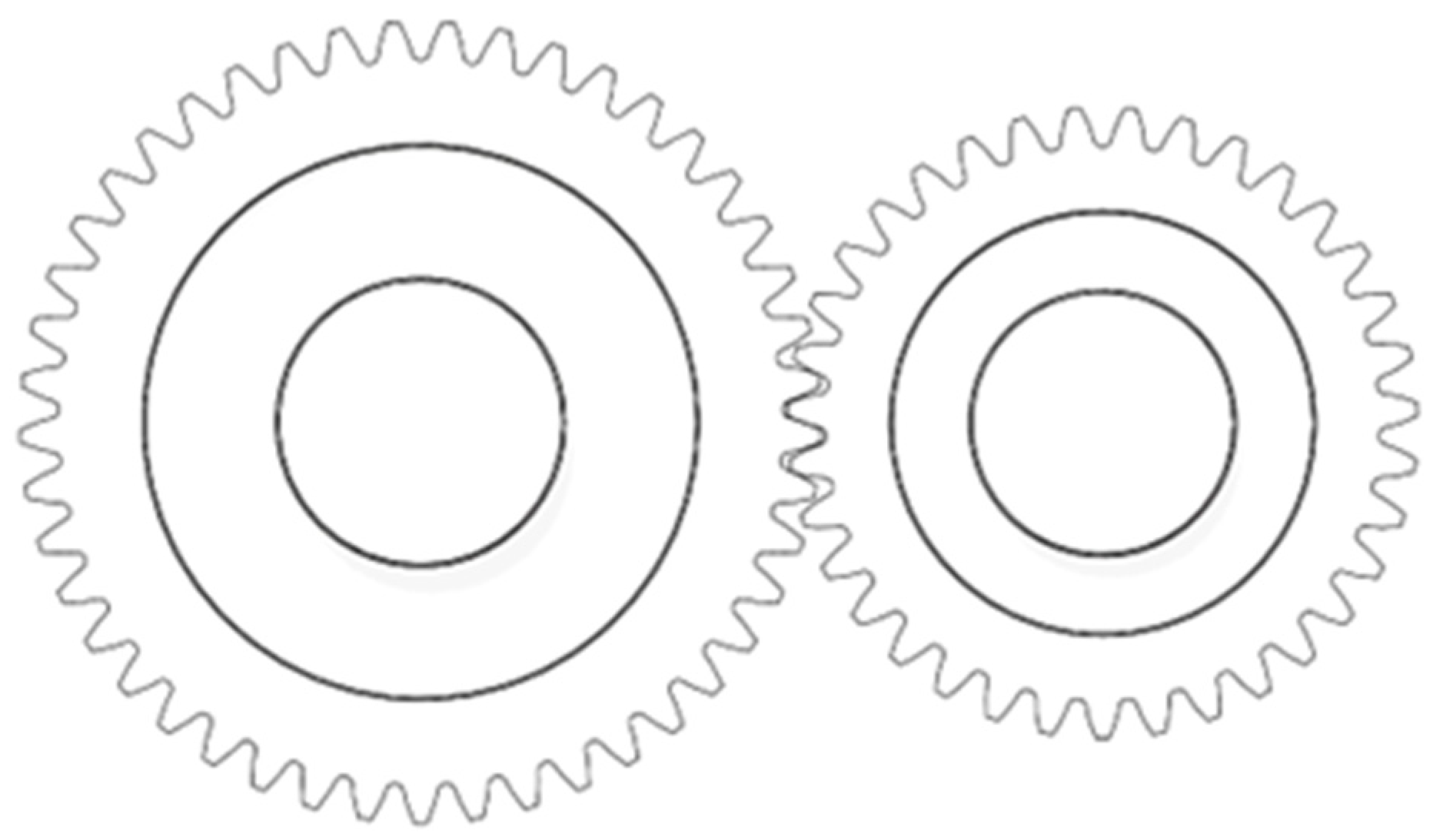
According to the parameters of Table 1, and the parameters of the large gear module 1.5, number of teeth 42, indexing circle diameter 125 mm, pinion module 1.5, number of teeth 35, indexing circle diameter 105 mm, tooth width 15 mm, using SolidWorks (2022) to build models, the cylindrical gear model is constructed, and the three-dimensional modeling of the gear is carried out by SolidWorks. The model is shown in Figure 1.
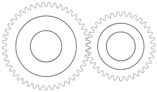
Figure 1.
Schematic diagram of the 3D model of the transmission gear.
The impact of numerical simulation parameters on the simulation outcome is significant. This study uses the software Shondy (2.5) for simulations of gear simulation in the solid region, where material properties are defined under physical properties, with wall surfaces set to exhibit no-slip behavior. The gear model is transformed from a stationary to a rotating part, with speed and thermal boundary conditions applied. The study investigates the influence of injection angles (60°, 75°, 90°, 105°) [25] on gear lubrication at an injection pressure of 0.5 MPa. The small gear acts as the driver, rotating at 5000 RPM, while the large gear is the driven wheel, rotating at 4166.66 RPM. The lubricant is 10w-40 grade oil with a kinematic viscosity of 0.0000208, specific heat capacity of 4431 J/kg·k, thermal conductivity of 0.173 W/mK, and expansion coefficient of 0.0007709/k. The simulation analysis for spray lubrication is conducted at an oil temperature of 40 °C.
3.2. Analysis of the Influence of Injection Angle on Oil Jet Lubrication
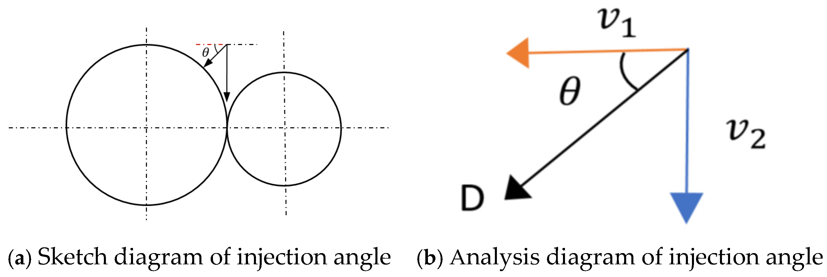
The jet angle is defined as the angle between the left side of the horizontal line and the injection angle, as shown in Figure 2a.

Figure 2.
The schematic analysis diagram of the spraying angle.
Figure 2b indicates that lubricant sprayed at a specific angle onto the gear surface decomposes into tangential and normal velocities, affecting tooth surface pressure and gear transmission efficiency. At the injection point (D), with an angle of θ and a velocity of v, the lubricant’s tangential and normal velocities vary, impacting lubrication effectiveness. Consequently, it is essential to investigate the influence of injection angles on lubrication.
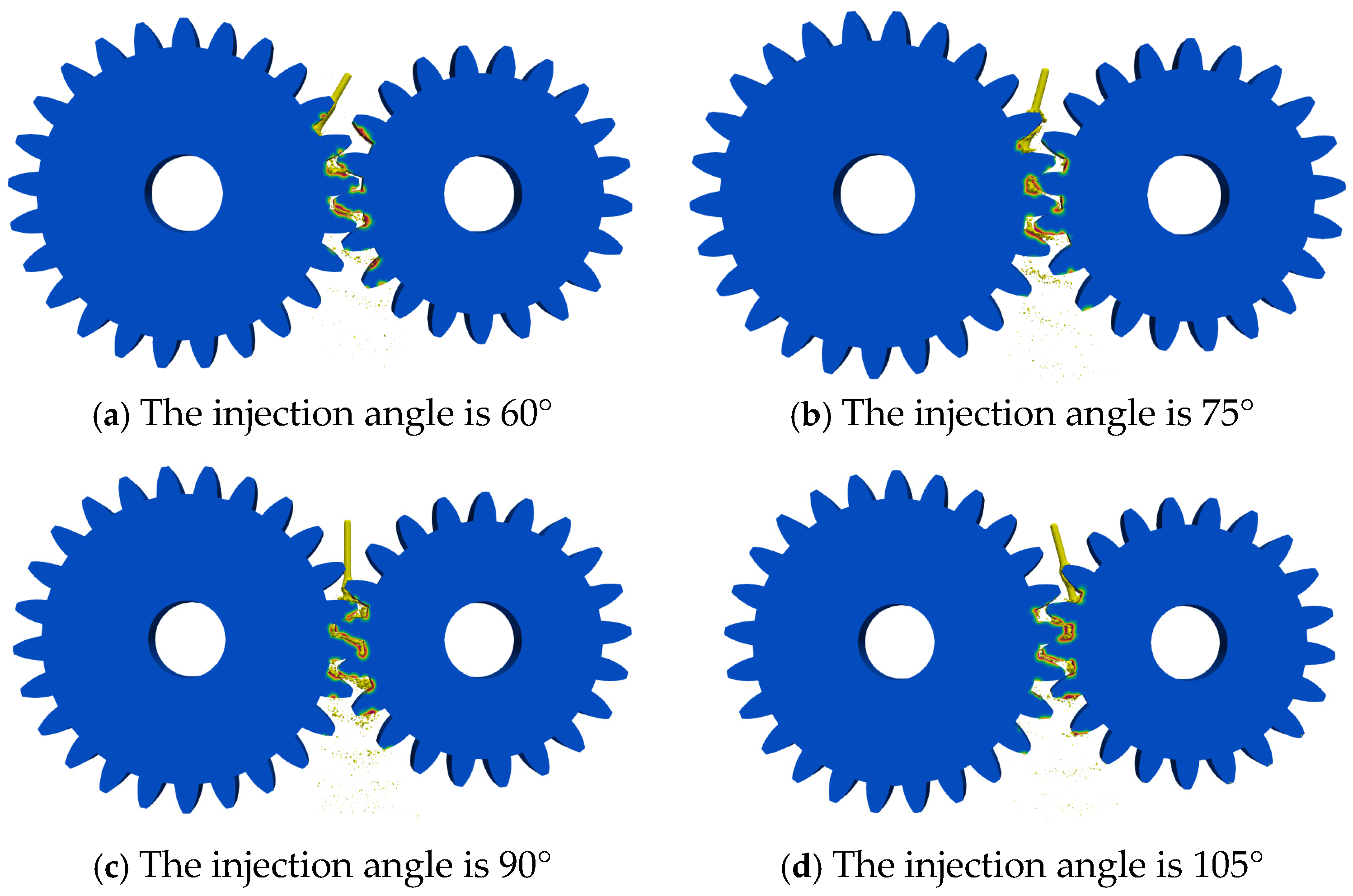
As shown in Figure 3, in order to ensure efficient lubrication, a reasonable oil injection angle should be selected for numerical simulation. The injection angles were selected as 60°, 75°, 90°, and 105° for gear lubrication research and analysis.

Figure 3.
Diagram of gear lubrication with different injection angles.
4. Numerical Analysis of Gear Lubrication at Different Injection Angles
4.1. Numerical Analysis of Large Gear Coverage Under Different Incident Angles
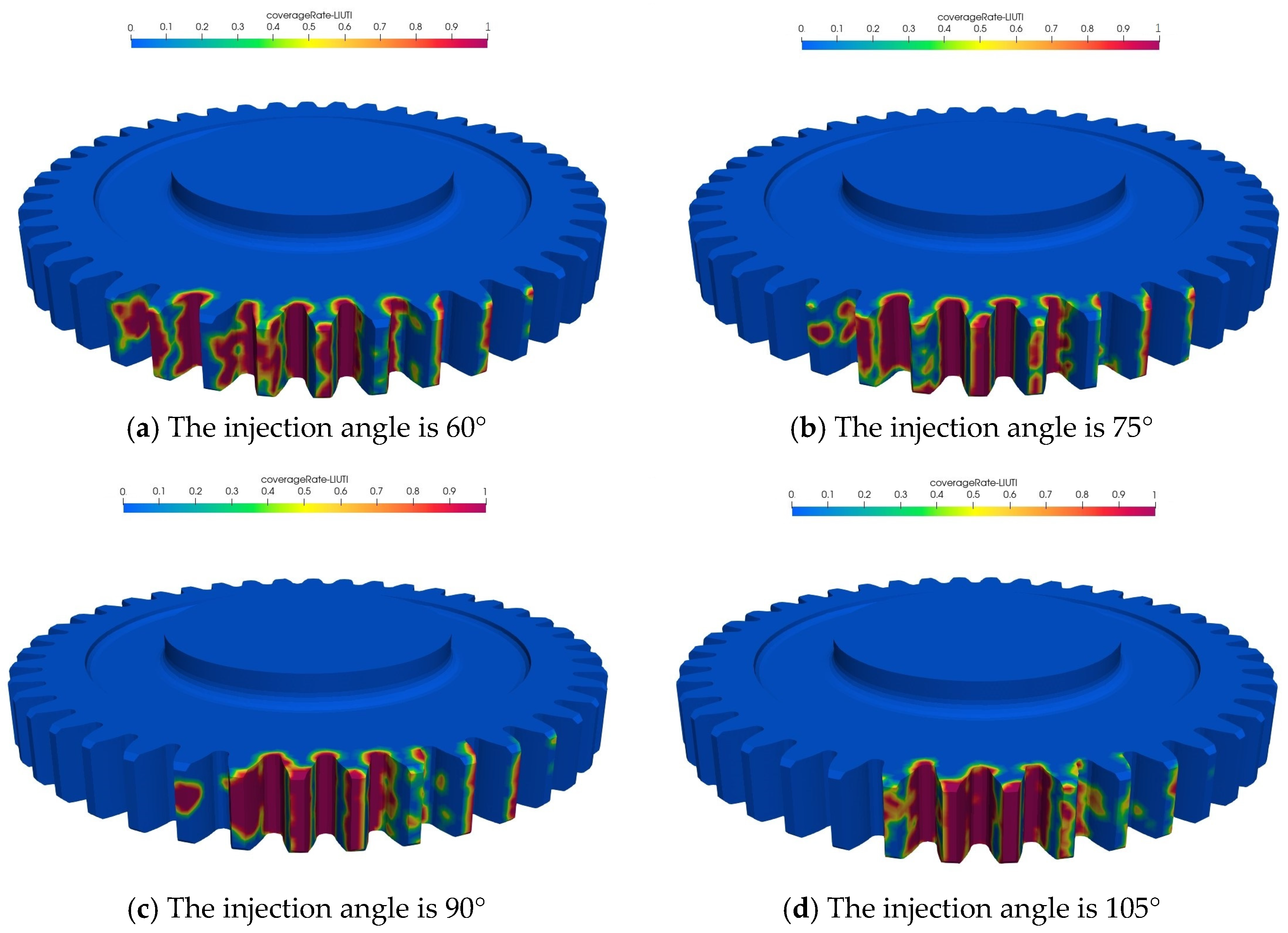
The coverage rate can accurately reflect the ability of oil to cover the surface of the transmission gear, thus reflecting the efficiency and state of gear lubrication on the side. The oil distribution data on the surface of the large gear are extracted, and the coverage distribution cloud diagram of the large gear is obtained as shown in Figure 4.

Figure 4.
Distribution of large gear coverage under different injection angles.
Figure 4 reveals that the large gear’s surface coverage, as indicated by the cloud map, initially increases and then decreases with a rising injection angle. At 60°, coverage is minimal and fragmented. Progressively, at 75°, continuity improves significantly, peaking at 90° with maximum, most uniform coverage, and darkest cloud map color, indicating optimal lubrication. Beyond 90°, at 105°, coverage and continuity diminish. Extracted data yield the large gear coverage curve in Figure 5.

Figure 5.
The large gear coverage curves at different injection angles.
As demonstrated in Figure 5, the lubricant coverage rate on the gear tooth surface initially increases with the injection angle, reaching a peak before decreasing. It is noteworthy that as the angle approaches 90°, coverage significantly improves, with vertical injection yielding the highest rate. This trend underscores the superior coverage achieved with vertical lubricant application. However, at 105°, direct gear interaction diminishes, reducing coverage. Consequently, to ensure optimal oil distribution and direct gear contact, lubrication system design should incorporate vertical injection or multi-nozzle direct injection methods.
4.2. HTC Analysis of Heat Dissipation of Large Gear Tooth Surface at Different Injection Angles
HTC (convective heat transfer coefficient) is the main heat transfer mode between the transmission gear and the lubricating oil. Therefore, the analysis of HTC can more intuitively express the influence of injection angles on gear lubrication. The oil distribution data on the surface of the large gear are extracted, and the HTC distribution cloud map of the large gear is obtained as shown in Figure 6.
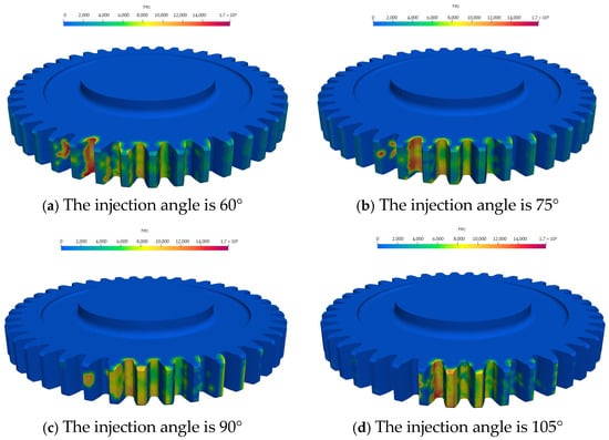
Figure 6.
Distribution of large gear dissipation HTC under different injection angles.
Figure 6 shows that the area encompassed by the HTC cloud image on the gear surface initially expands and then contracts with the rising injection angle. This pattern is consistent with the gear coverage rate discussed gear coverage rate. At 60°, direct lubricant spraying yields a deeper cloud image within the meshing zone. Increments in the angle further enhance the coverage area, keeping a uniform coloration. However, at 105°, the indirect lubricant action results in a reduced and lighter cloud image area. The extracted data yields the HTC curve for the large gear, depicted in Figure 7.
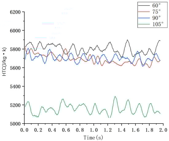
Figure 7.
The large gear heat dissipation HTC curves at different injection angles.
Figure 7 illustrates that HTC values exhibit a slight decline with increasing injection angles. Notably, at 105°, HTC on the tooth surface significantly decreases, attributed to the lack of direct contact with lubricating oil, which instead acts indirectly on the large gear through gear meshing. The curve reveals that when lubricating oil is directly sprayed onto the tooth surface, HTC remains relatively stable. Hence, for optimal gear lubrication and heat dissipation design, it is imperative that lubricating oil directly interacts with the tooth surface to maximize the heat dissipation effect.
4.3. Numerical Analysis of Pinion Coverage Under Different Injection Angles
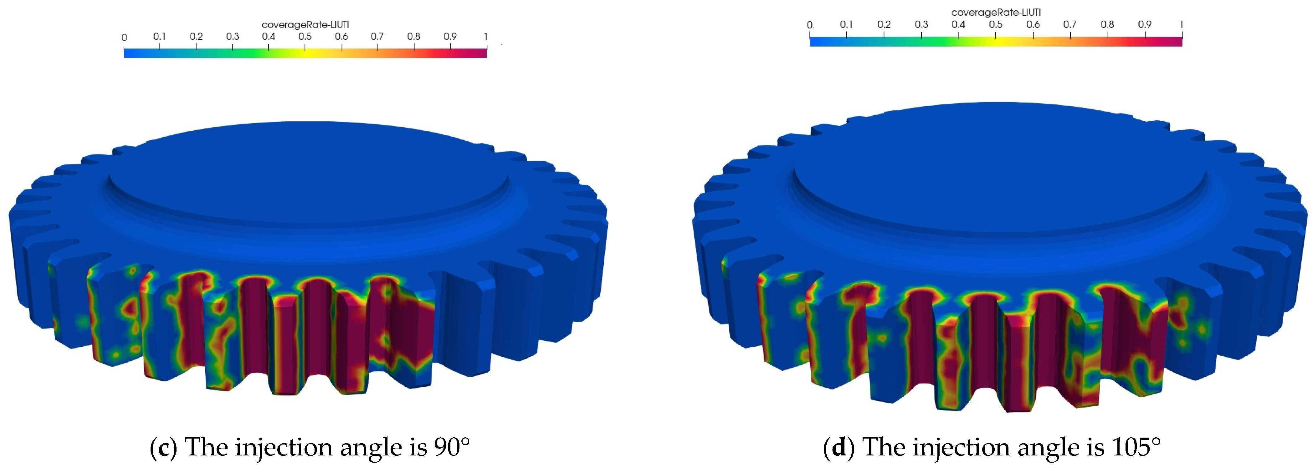
The coverage rate precisely indicates the oil’s capacity to cover the gear surface, thereby reflecting the efficiency and condition of gear lubrication. Extracting oil distribution data from the gear surface yields the coverage distribution cloud map depicted in Figure 8.
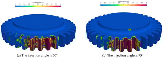
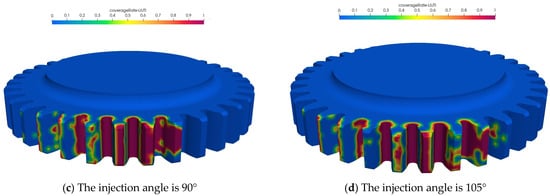
Figure 8.
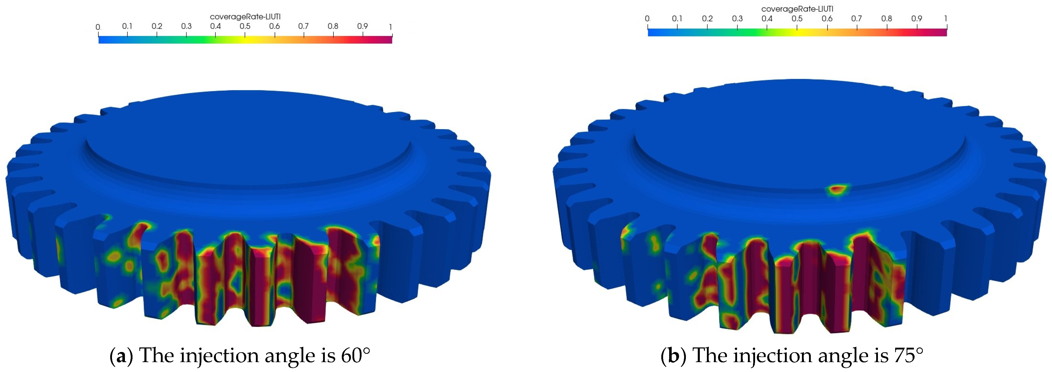
Distribution of small gear coverage under different injection angles.
Figure 8 illustrates that with increasing injection angle, the lubricant coverage area on the large gear surface initially expands, reaching a maximum at 90°, where coverage is most uniform and intensive, indicating optimal lubrication effectiveness. Below 90°, particularly at 60°, coverage is reduced and fragmented due to indirect lubricant application. At 75°, coverage remains relatively stable. Beyond 90°, at 105°, coverage diminishes, but still surpasses that of the sub−90° angles, highlighting the significant difference between direct and indirect lubricant application. The gear coverage curve, depicted in Figure 9, further exemplifies these trends.
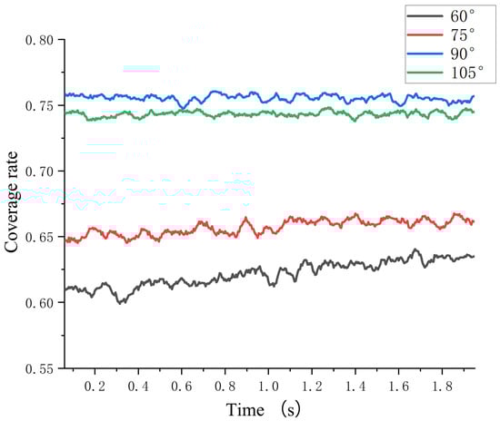
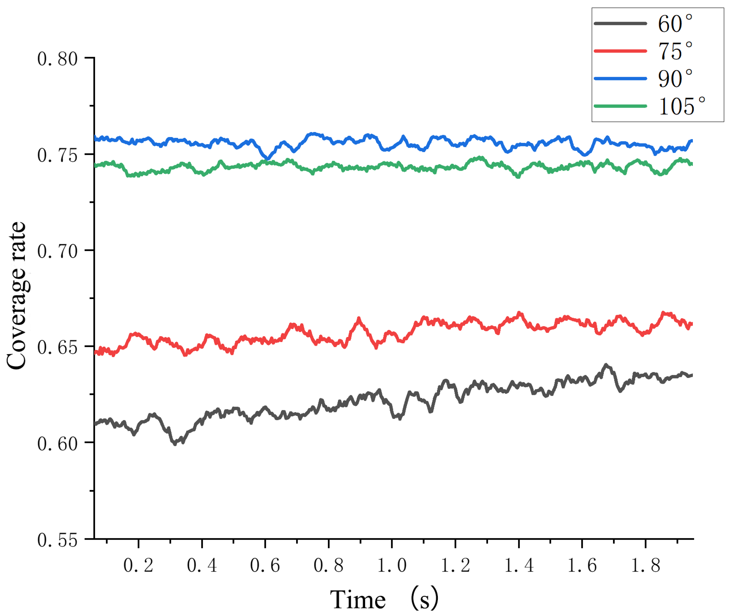
Figure 9.
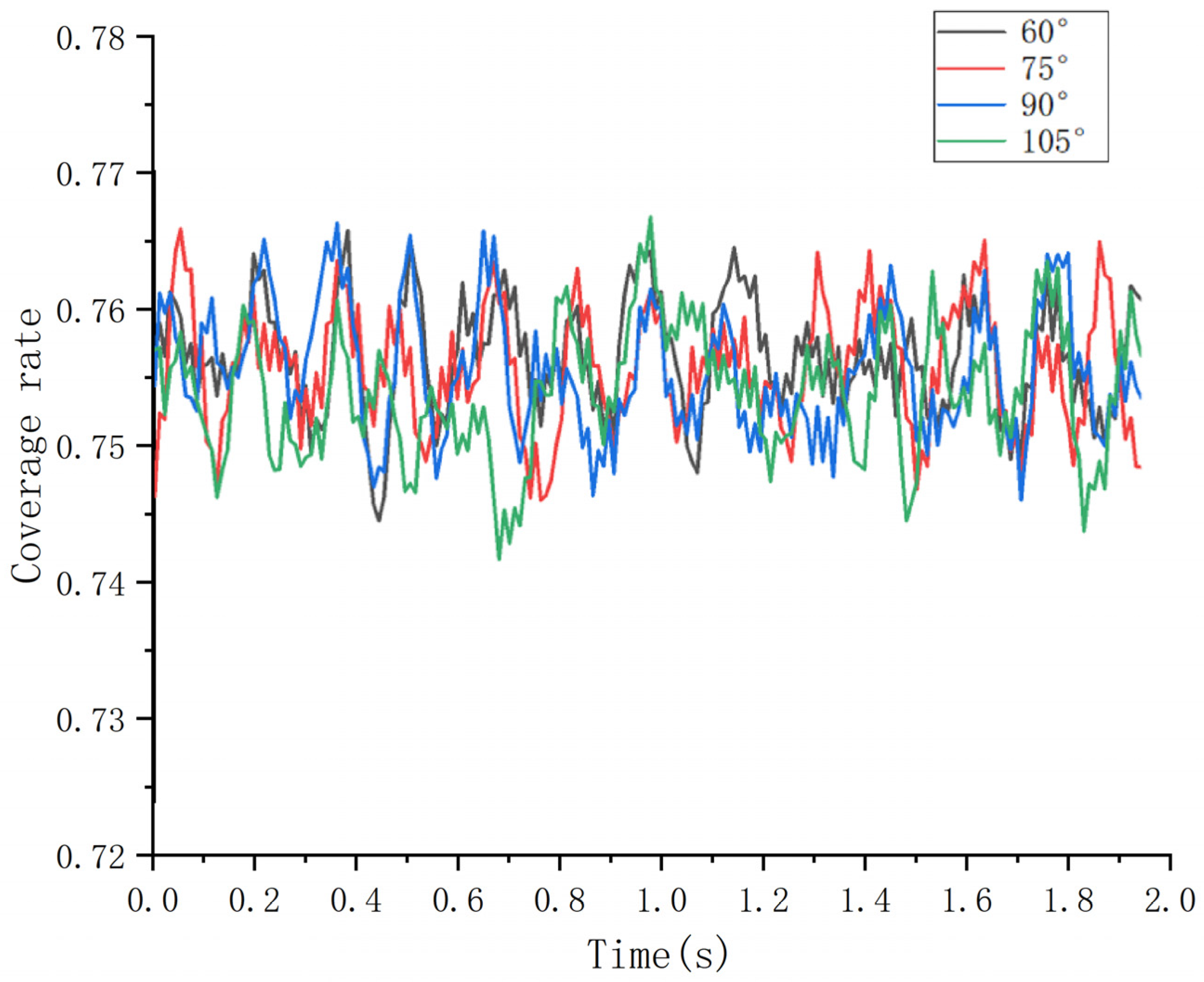
The small gear coverage curves at different injection angles.
Figure 9 demonstrates that lubricant coverage on the gear tooth surface initially rises with the injection angle, reaching a peak before declining. Notably, at 90°, vertical injection achieves the highest coverage, significantly outperforming other angles. This is attributed to the direct interaction of the lubricant with the gear teeth. Below 75°, reduced coverage occurs due to indirect lubricant application. As the angle exceeds 105°, coverage diminishes, indicating the importance of precise angle selection in lubrication system design to ensure maximum oil distribution and direct gear contact. Vertical or multi-nozzle direct injection is recommended for optimal performance.
4.4. HTC Analysis of Heat Dissipation of Pinion Tooth Surface Under Different Injection Angles
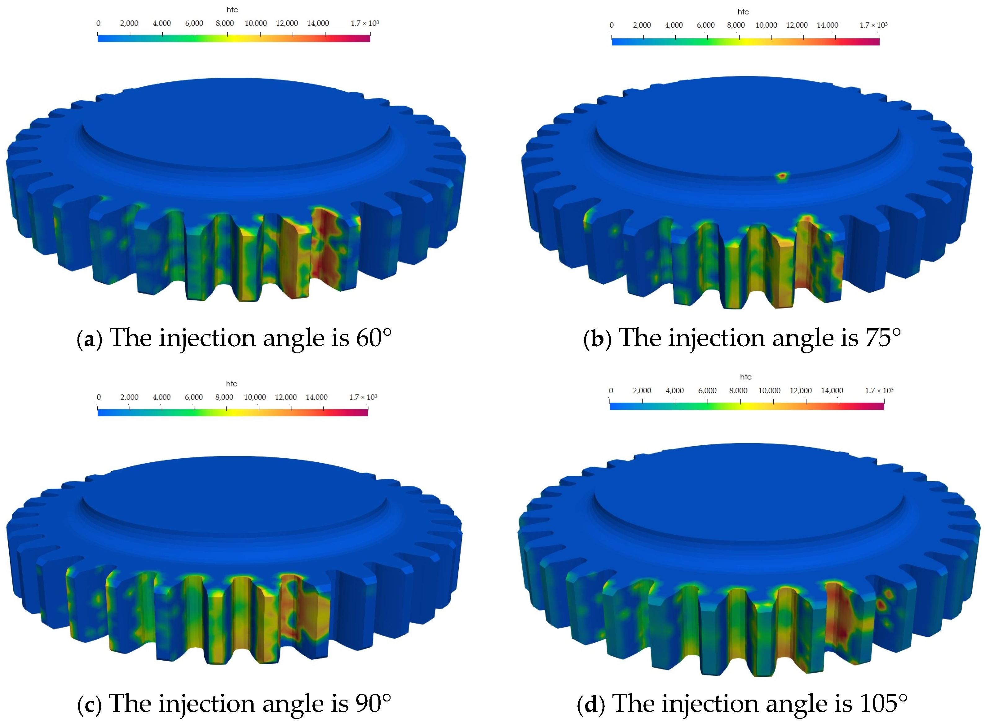
HTC (convective heat transfer coefficient) is the main heat transfer mode between the transmission gear and lubricating oil. Therefore, the analysis of HTC can more intuitively express the influence of injection angles on gear lubrication. The oil distribution data on the surface of the pinion are extracted to obtain the HTC distribution cloud map shown in Figure 10.

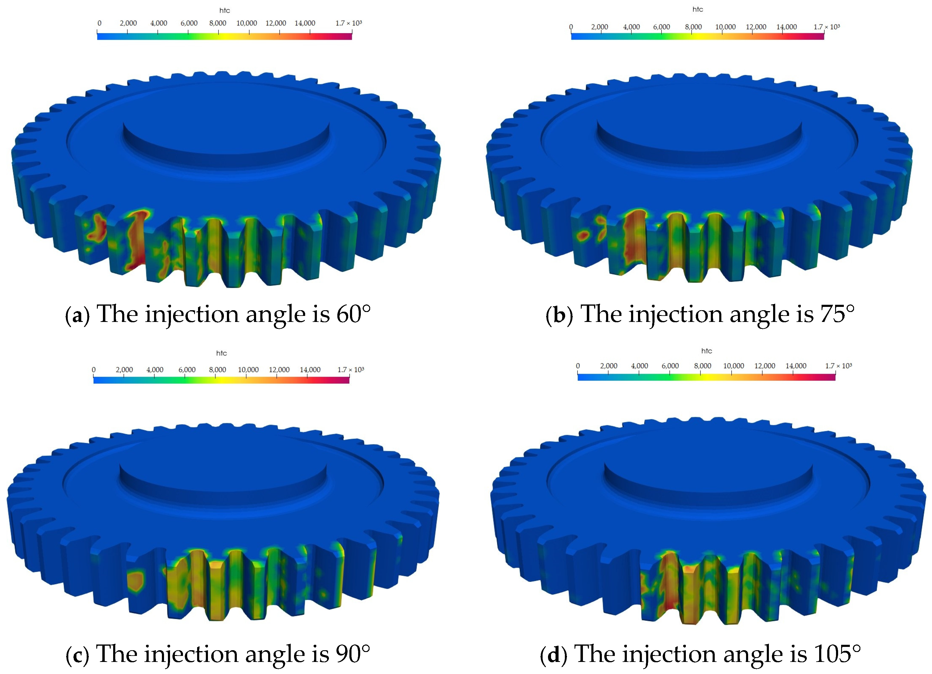
Figure 10.
Distribution of small gear dissipation HTC under different injection angles.
It can be seen from Figure 10 that as the injection angle increases, the area covered by the HTC cloud image on the gear surface increases first and then decreases, which is similar to the conclusion of the gear coverage rate analyzed above. When the injection angles are 60° and 75°, because the lubricating oil is not directly sprayed on the gear surface, the cloud image in the meshing area is shallow. With the increase in the spray angle, the coverage area of the cloud image increases, and the color becomes darker as a whole. When the injection angle is increased to 105°, the color and coverage area of HTC are smaller than that of vertical injection, the coverage area of the cloud map is reduced, and the color is generally unchanged, indicating that in the lubrication process, the lubrication and heat dissipation effect of the lubricating oil directly acting on the tooth surface is more superior. With vertical injection, the oil’s comprehensive heat dissipation effect is best. The data are extracted to obtain the HTC curve of the pinion shown in Figure 11.

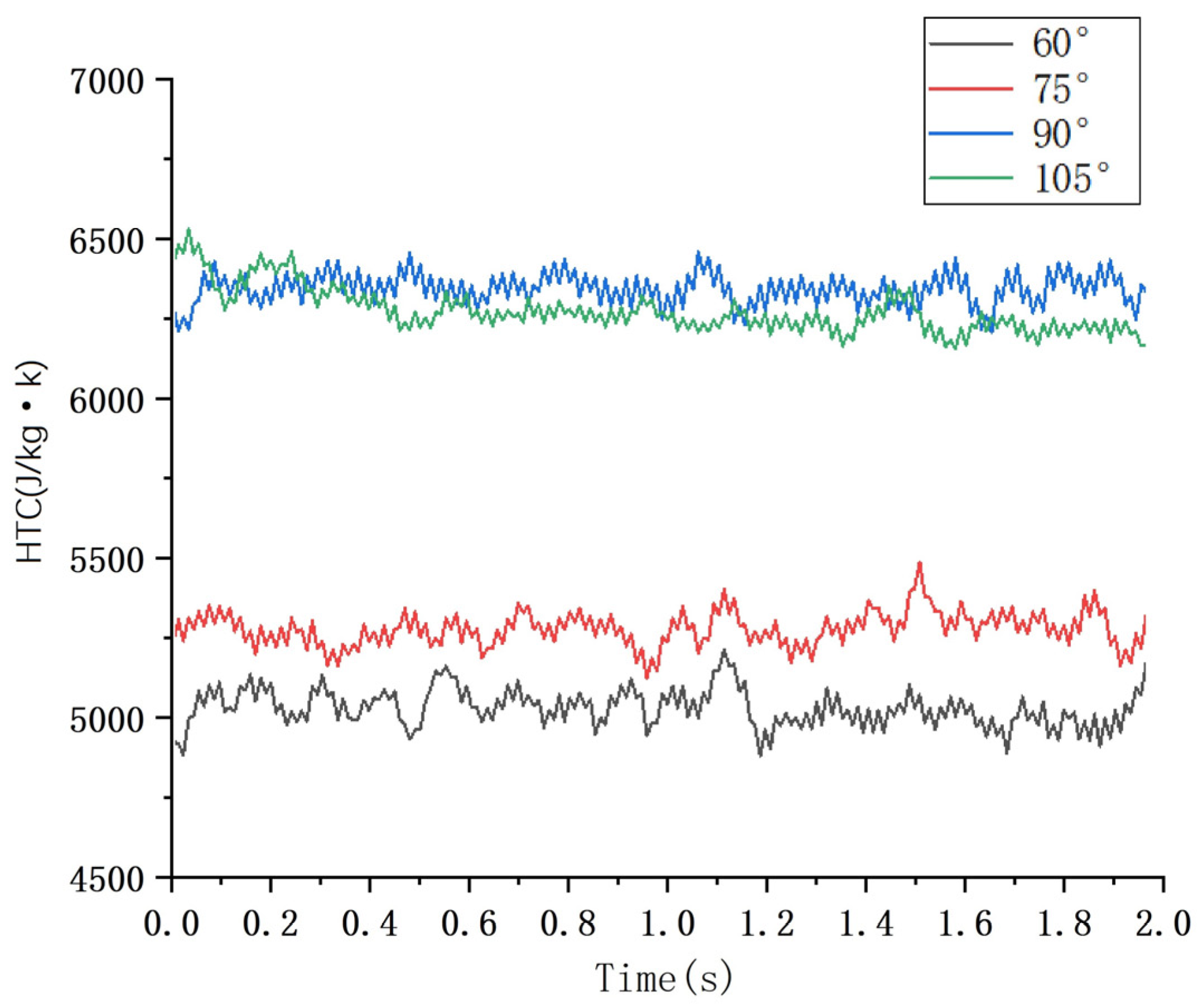
Figure 11.
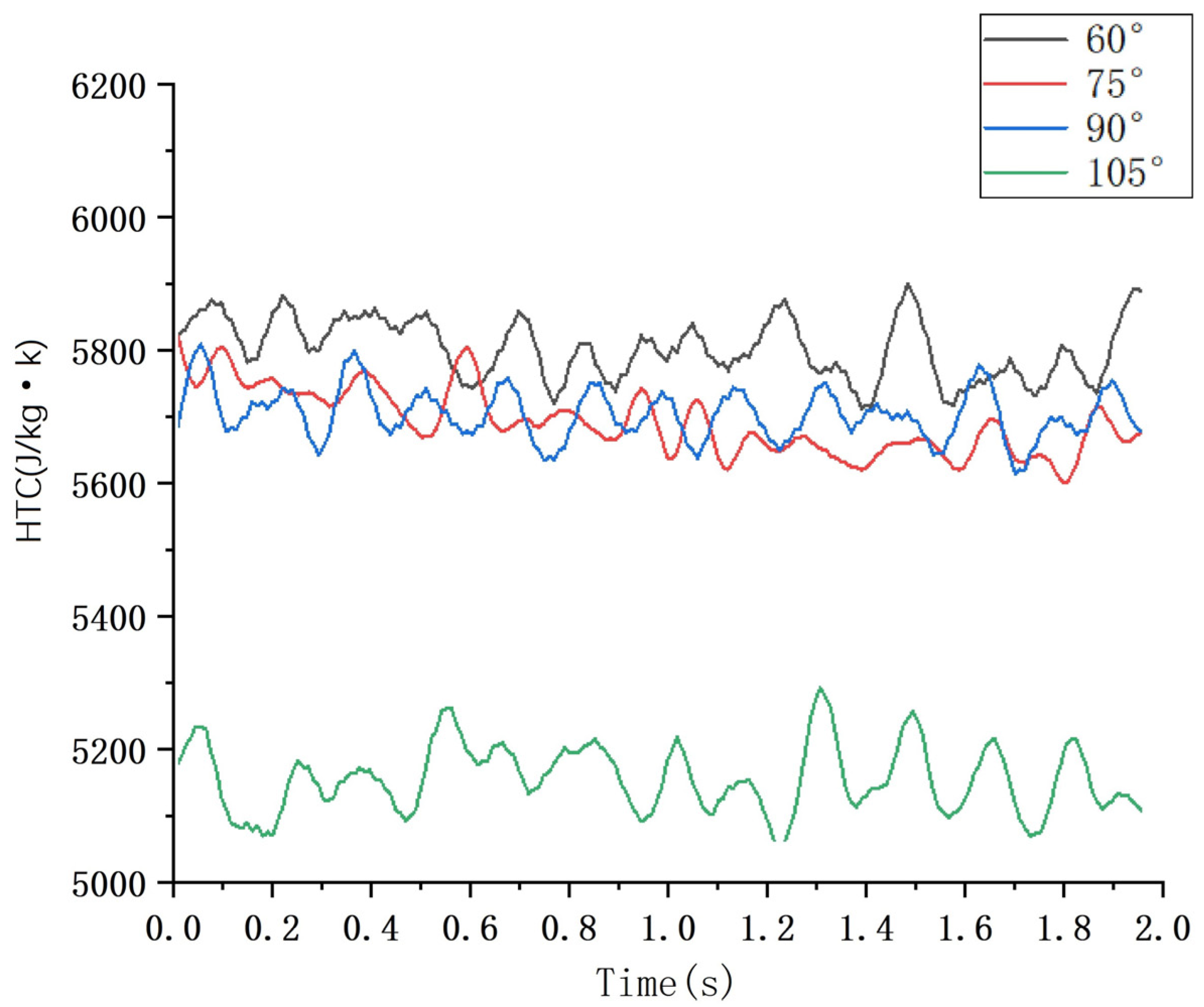
The small gear heat dissipation HTC curves at different injection angles.
From Figure 11, it can be seen that with the increase in the injection angle, the value of HTC increases slightly. When the injection angle is 90°, the value of HTC reaches the maximum. Maximum value varies up and down 6400. When the injection angle continues to increase, the value of HTC decreases slightly. When the injection angle is less than 90°, varying up and down at 6200, the lubricating oil acts indirectly on the pinion, so the HTC of the tooth surface decreases greatly. It can be seen from the curve that the lubricating oil must interact directly with the tooth surface to ensure that the heat dissipation effect of the lubrication reaches the maximum. Therefore, considering the lubrication and heat dissipation effect of the two gears, when the injection angle is 90°, the lubrication and heat dissipation are obviously better than other injection angles.
5. Lubrication Test Analysis of Gear
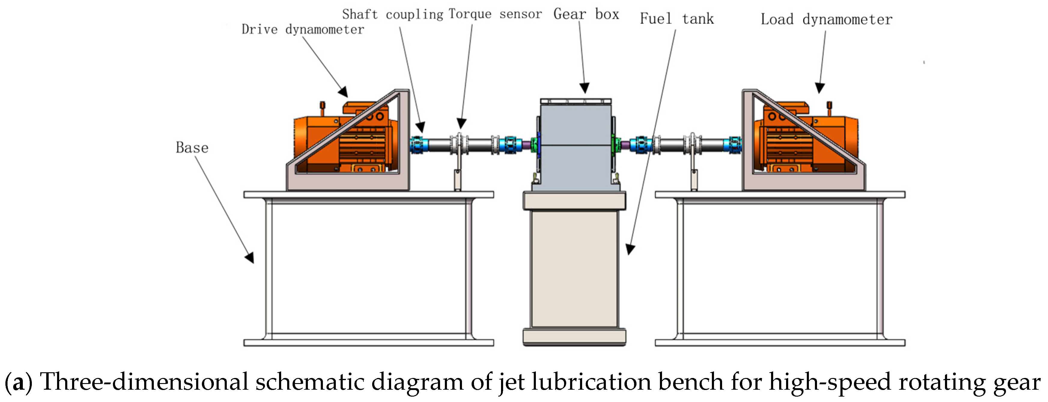
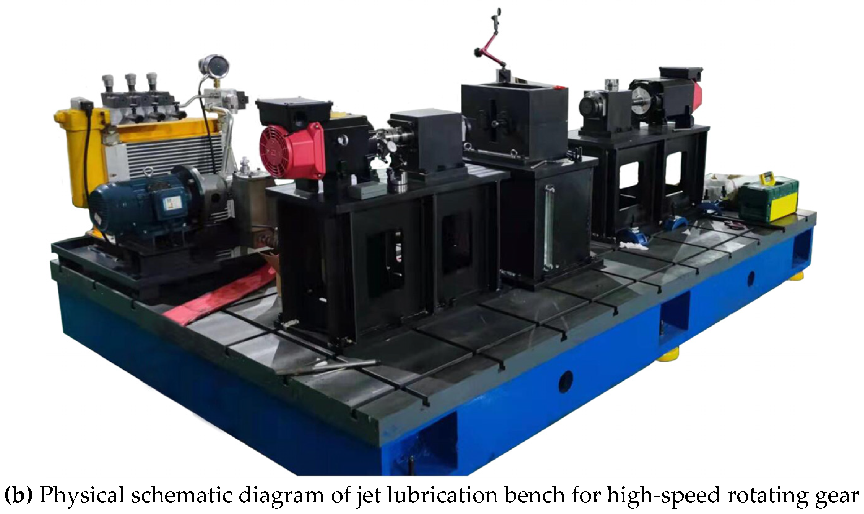
While the simulation captures the objective trends of injection angle effects on gear lubrication, discrepancies between the simulation and practical results are inevitable. In order to validate the accuracy and effectiveness of the jet lubrication model, this study establishes a gear lubrication test platform, as shown in Figure 12. This platform, designed for precise control and ease of assembly, comprises a gearbox, motor, injection system, test system, and sensors to investigate the impact of jet angles on gear lubrication.
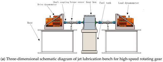

Figure 12.
Schematic diagram of high-speed rotary gear injection lubrication bench.
5.1. Establishment of High-Speed Rotating Lubrication Test System
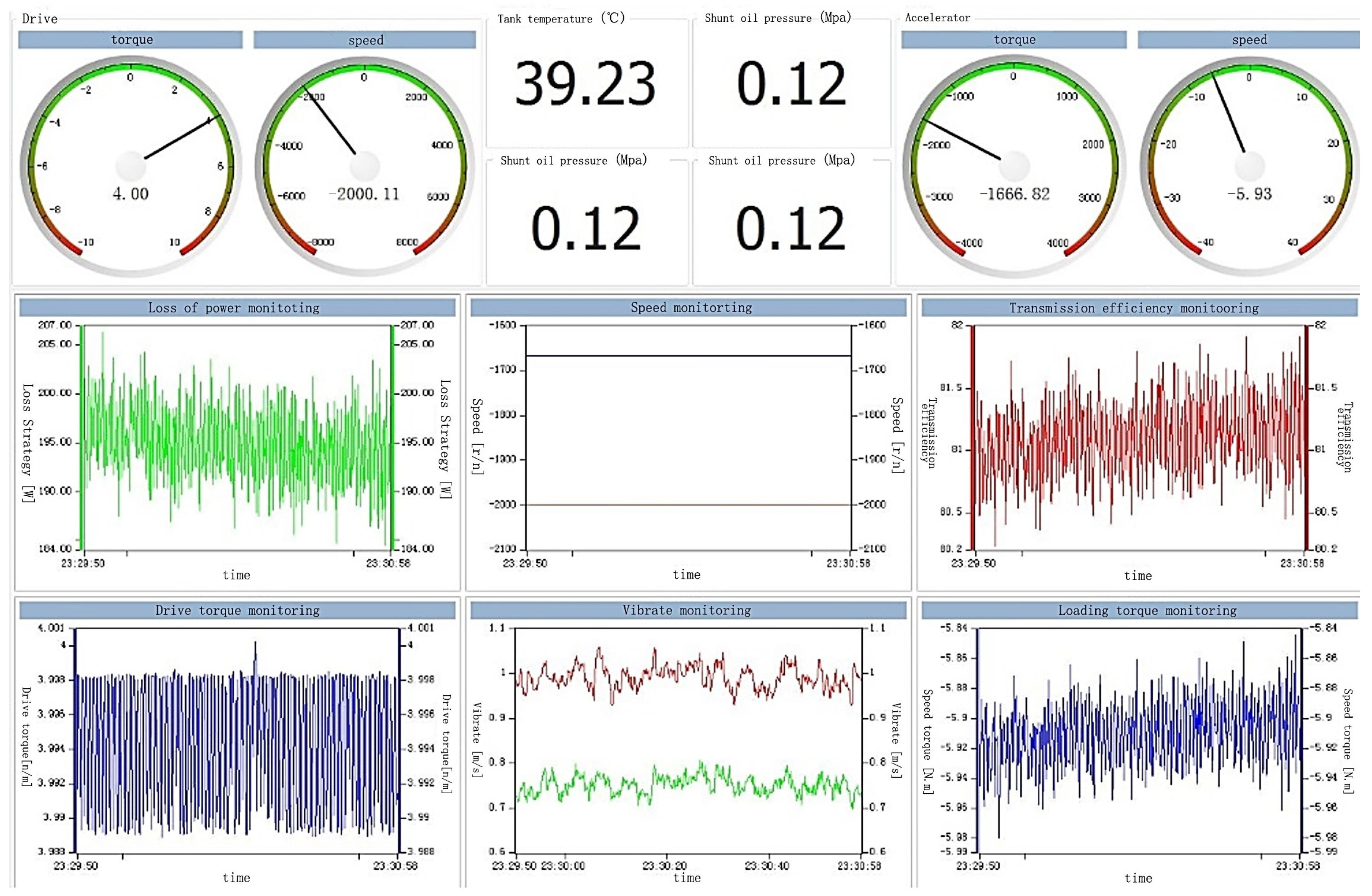
A data acquisition system tailored for the test was developed. The high-speed rotary gear injection lubrication software (1.1) test system incorporates a drive and loading system, utilizing a reliable frequency converter, PLC, and high-precision torque sensor. Capable of controlling speeds up to 8000 r/min, the system features functions for monitoring power loss, speed, transmission efficiency, drive torque, vibration, and load torque. The system software interface is depicted in Figure 13.
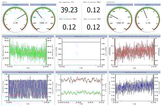
Figure 13.
The high-speed rotating gear injection lubrication test system software interface.
The software test system facilitates real-time observation of the test process, thereby enabling control of the drive motor speed, activation of the pressure control system, and setting of the loading torque. In addition, it enables the detection of system vibrations and the acquisition of transmission efficiency and vibration data, thereby ensuring bench stability and the reliability of test data.
5.2. High-Speed Rotation Lubrication Test
The high-speed rotation lubrication test explores the internal influence of the injection angle on gear lubrication. The specific test steps are as follows:
- First of all, the bench debugging, installed in the special production of the top cover to meet the injection angle requirements.
- Then, open the test bench through the system software to adjust the speed and torque; the hydraulic station system is opened, and the system works smoothly. The data under this working condition are recorded as the system torque when there is oil injection lubrication, and the average value of each group of data is recorded five times.
- Subsequently, the hydraulic system is shut down. At this point, the gear is in an idle state. To eliminate the power losses resulting from components such as the gearbox bearings and gear meshing during the test, when the gear was operating within the previous hydraulic system, its surface had been enveloped by an oil film. As a result, the system remains in a stable state. The system torque data under the magnetic condition are recorded as the system torque without oil injection lubrication, and the average value of each set of data is recorded three times.
- Finally, using the data of the injection state measured in (2) minus the data of the injection state measured in (3), the data without the injection state are measured, and the result is the torque (power loss) of the high-speed rotating gear caused by injection lubrication.
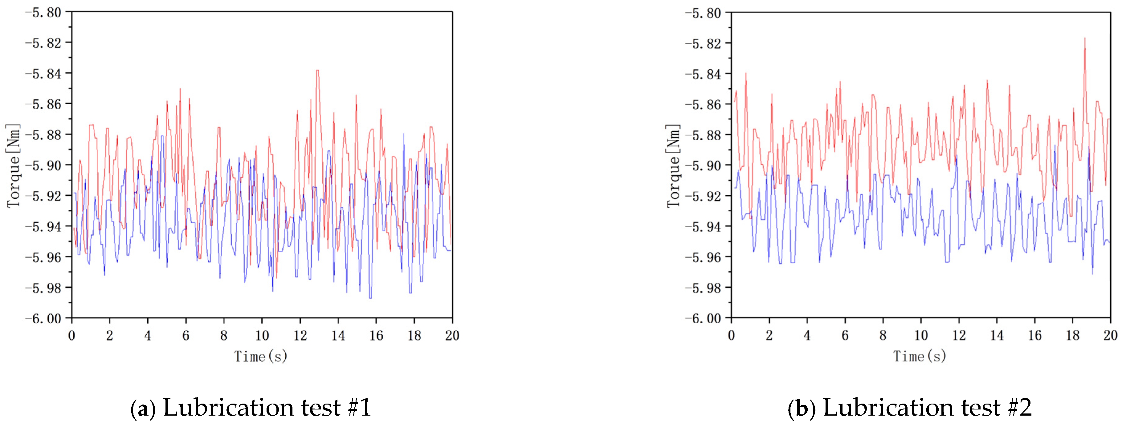
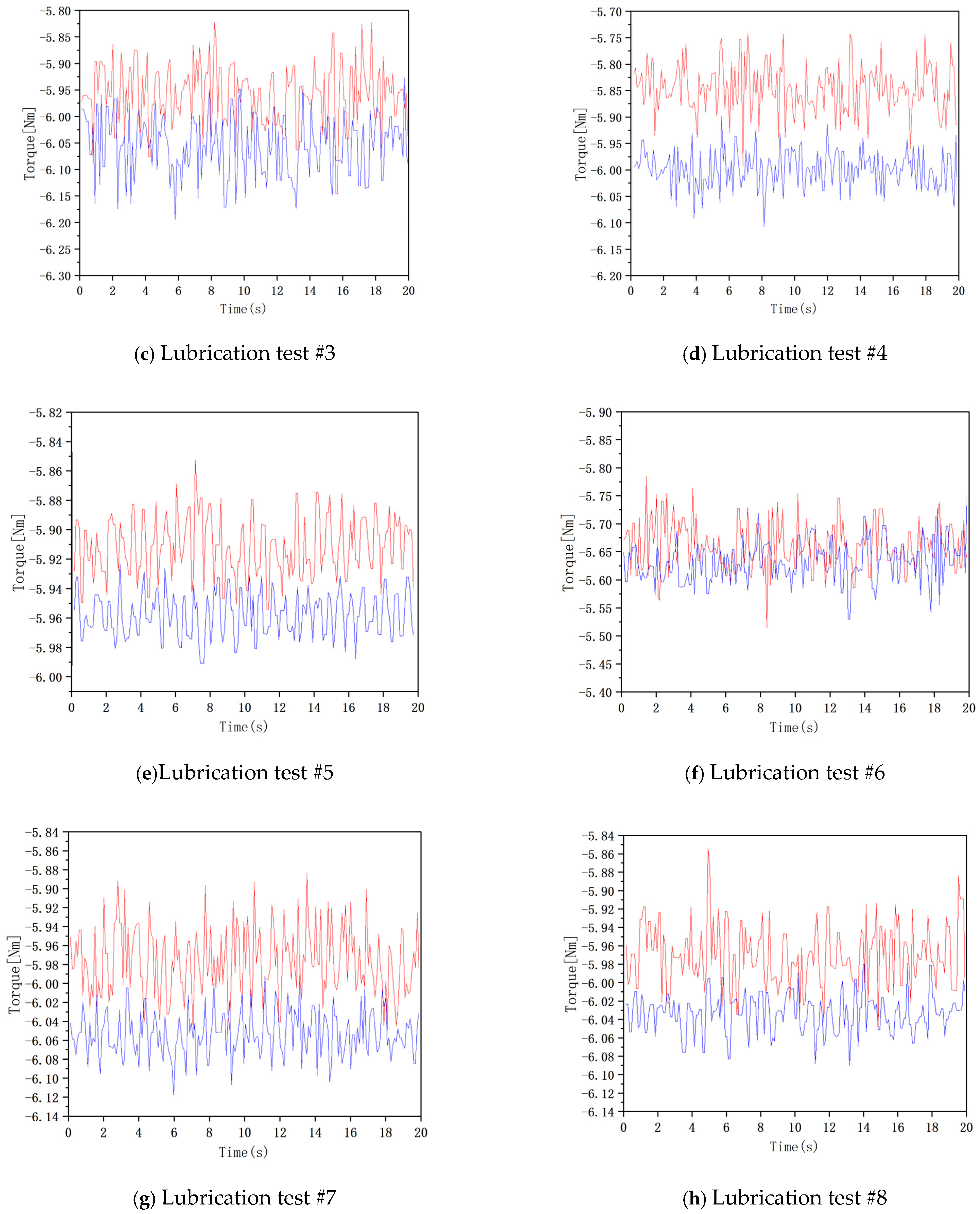
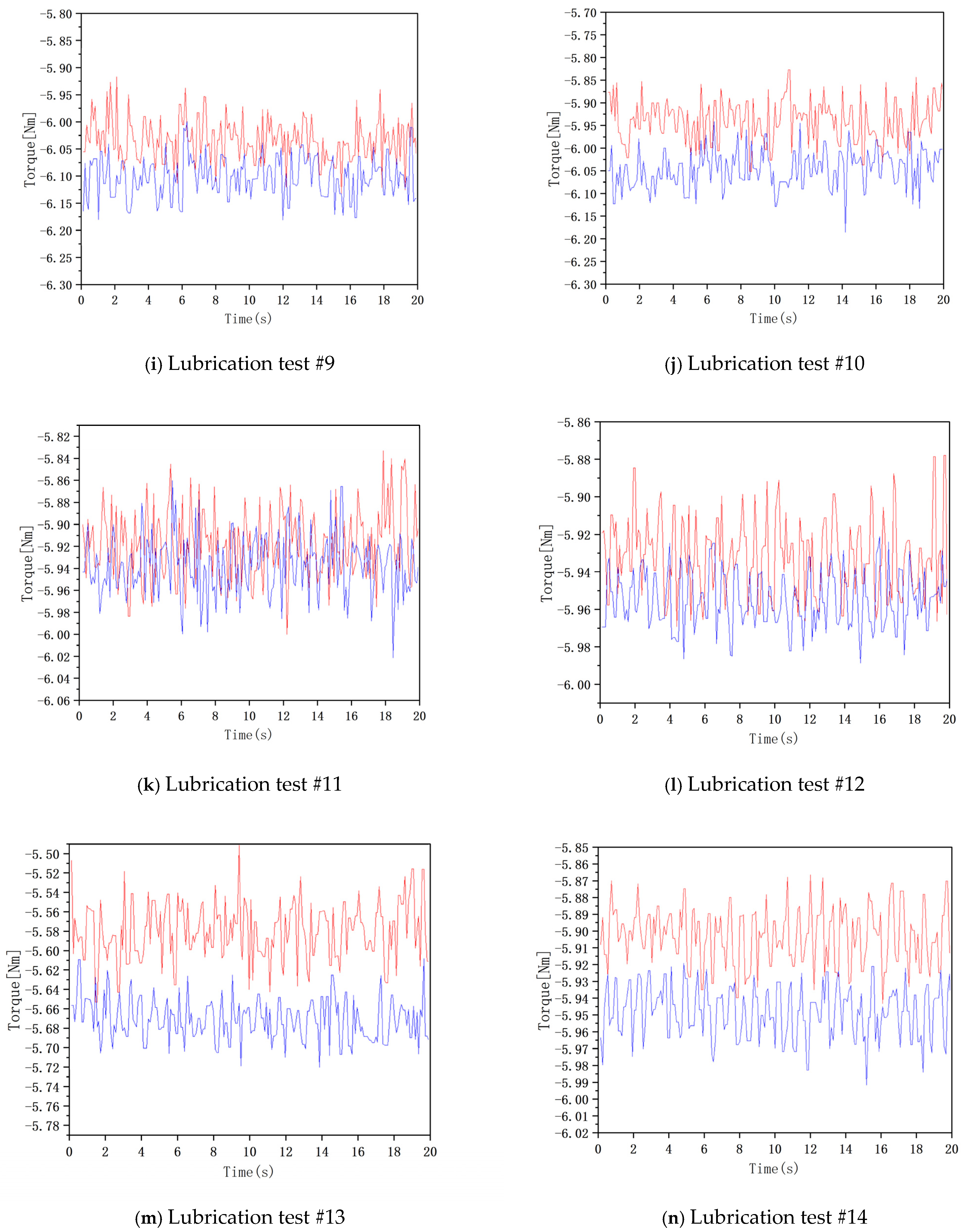
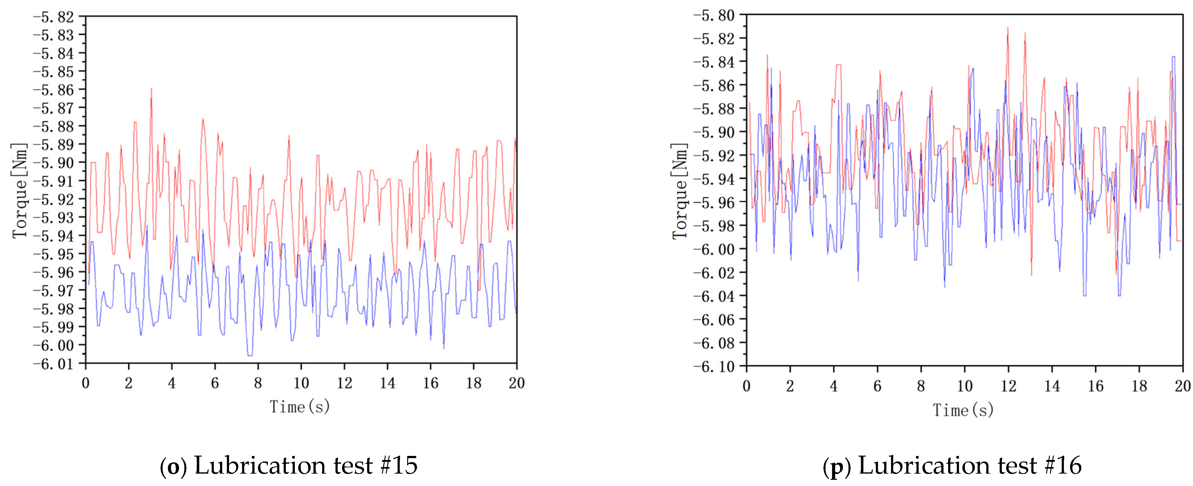
By recording and data sampling for 20 s, the original data of the following 16 groups are obtained as follows.
In order to obtain the influence law of lubricating oil utilization rate of high-speed rotating gear, the data shown in Figure 14 are sorted out, which the red line shows the torque data at the input and the blue line shows the torque data at the output and the orthogonal test statistical. And the orthogonal test statistical table of injection lubrication torque shown in Table 2 is obtained.

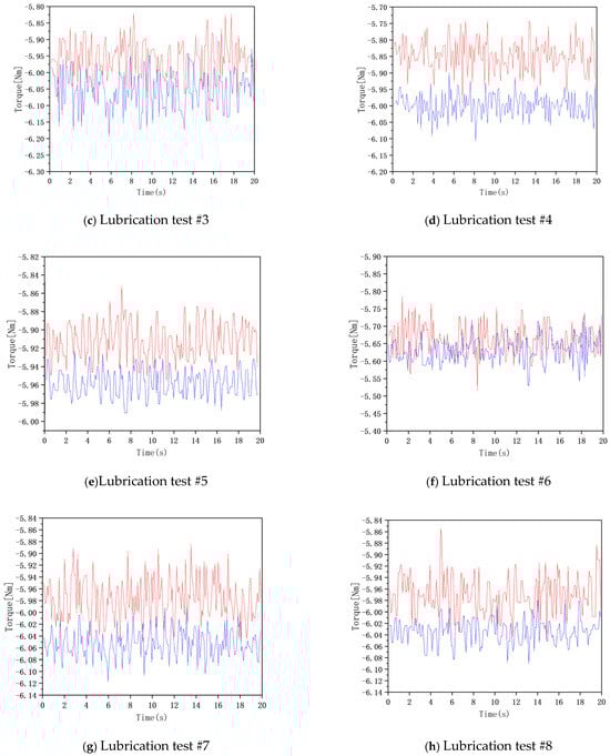
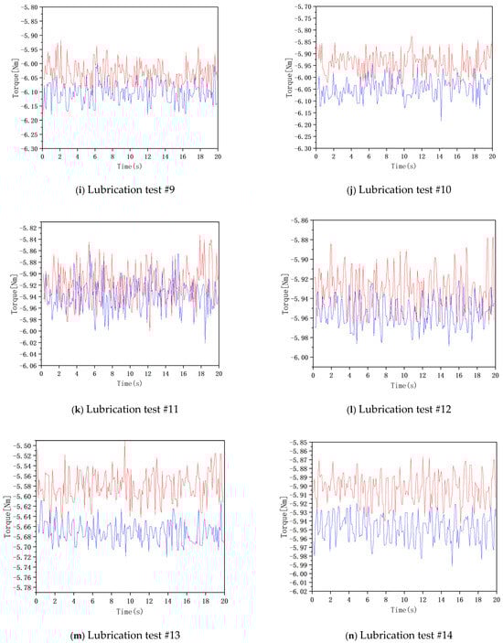
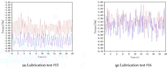
Figure 14.
The high-speed rotary lubrication test raw data graph.
Table 2.
The gear injection lubrication torque statistics table.
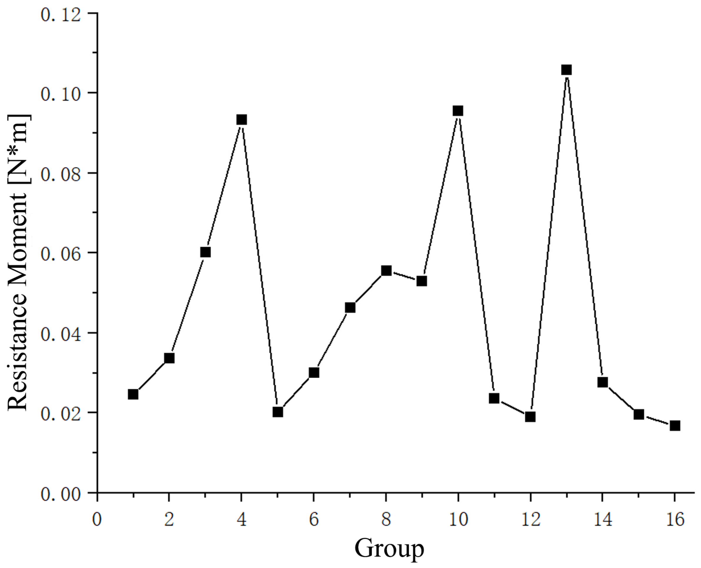
According to the statistical table of gear spray lubrication torque in Table 2, the torque value is extracted to further draw the change curve of gear spray lubrication torque in Figure 15, which is convenient to observe the change in gear torque under different conditions.
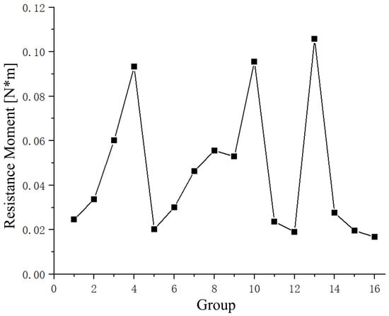
Figure 15.
The high-speed rotating gear jet lubrication torque variation graphs.
5.3. High-Speed Rotation Lubrication Test Data Analysis
The gear lubrication torque statistics in Table 2 demonstrate that the injection angle significantly affects lubrication performance. To further investigate this correlation and identify the optimal parameter combination, Table 3 presents an orthogonal range analysis table through inductive calculations based on the designed orthogonal experiment.
Table 3.
The gear injection lubrication orthogonal polar analysis table.
From the orthogonal range analysis table of gear injection lubrication in Table 3, the significant characteristics and influence relationship of each factor can be seen. Among them, is the average value of the test data at the same level in the corresponding column, and the larger indicates the greater torque at this level. Taking the injection angle as an example, the injection angle is 60°, 75°, 90°, 105°, for example, the corresponding is 0.05088, 0.04672, 0.03738, 0.04612, that is, . Because the torque generated during the injection lubrication process is as small as possible, the following judgment can be made. When the injection j angle is 90°, a smaller power loss can be obtained. Similarly, the optimal parameters of the high-speed lubricating gear are the incident distance of 3.5 cm, the incident diameter of 1.5 mm, and the gear speed of 2000 r/min.
In the analysis, delta represents the range of factors affecting the test results, with larger values indicating primary influence and smaller values suggesting secondary influence. The delta values for incident distance, injection angle, incident diameter, and rotational speed are 0.01483, 0.01350, 0.06210, and 0.02533, respectively. This reveals that the incident diameter exerts the greatest impact on jet lubrication loss, while the injection angle has the least. Consequently, the parameters’ influence decreases in the order of incident diameter, rotational speed, incident distance, and injection angle.
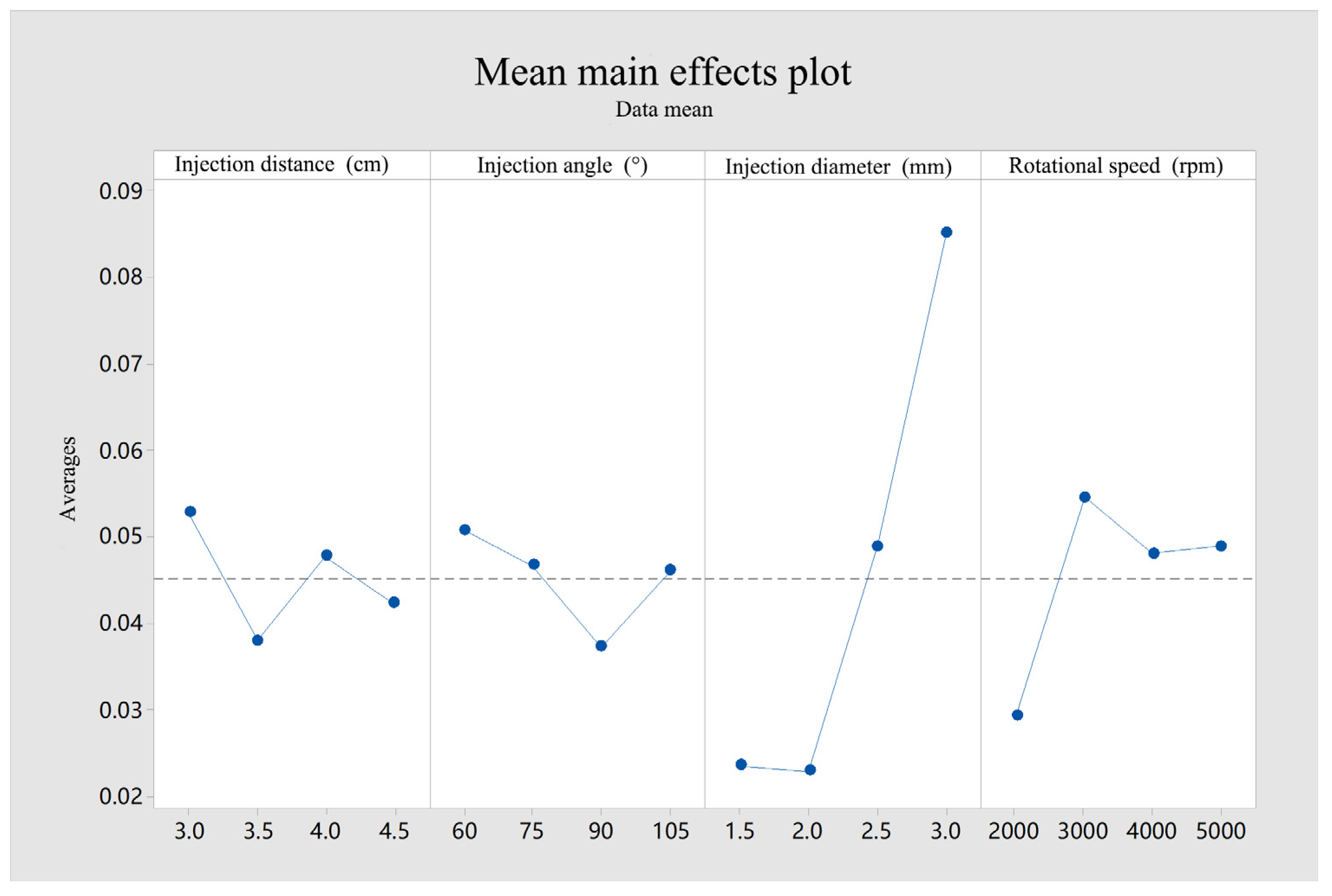
Table 3 analysis elucidates the inter-parameter influencing factors. Additionally, the variance table facilitates the construction of a mean main effect diagram, which visually represents the variation patterns of each factor.
Figure 16 illustrates that varying action parameters exert distinct influences on the test index. The steepness of the broken lines represents the factor’s impact, with greater slopes indicating more significant influence. Lower mean values correspond to reduced torque and power loss due to jet lubrication. Notably, as the injection angle increases, the mean line initially decreases, then rises, with the slope mirroring this trend, suggesting a marked effect of injection angle on lubrication efficiency.

Figure 16.
Mean main effects plot.
As the injection angle increases from 60° to 90°, there is a notable decrease in torque, signifying improved gear lubrication. Beyond 90°, however, torque sharply increases, indicating a surge in power loss, aligning with simulation outcomes. At 90°, optimal oil coverage, heat dissipation, and gear stability are achieved, minimizing power loss. Hence, 90° is identified as the optimal injection angle for lubrication.
Analysis indicates that lubrication is most effective at an injection angle of 90°. To delve deeper into the relationship between injection angle and torque, a regression analysis was conducted. The established regression equation, where y represents torque (N∙m), is the injection distance (cm), is the injection angle (°), is the incident diameter (mm), and is gear speed (rpm), is as follows.
After the above analysis, the optimal injection angle of high-speed rotating gear lubricating oil utilization is 90°.
6. Conclusions
Gear is very important in the transmission system, and jet lubrication is very important to stabilize power transmission and prevent excessive wear. In this study, the semi-implicit method of moving particles was used to study the lubrication characteristics of gear lubrication at different injection angles, and the oil coverage and heat dissipation were evaluated. The research results provide the optimal parameter combination for high-speed gear lubrication and obtain the optimal injection angle. Through simulation and experiment, the consumption of lubricating oil can be reduced and the transmission efficiency can be improved, which provides a reference for the actual production design. The specific contents are as follows:
- As the injection angle increases, the surface coverage of both the large and small rotating gears and the HTC initially show an increasing and then a decreasing trend, and both show the same lubrication law characteristics.
- When the high-speed rotating gear is in non-vertical incidence, because the lubricating oil is directly injected into one of the gears, it will inevitably cause the pressure of the tooth surface in direct contact with the lubricating oil to rise, resulting in power loss. As the injection angle gradually approaches vertical incidence, the oil acts on both transmission gears at the same time, and the oil coverage and HTC on the gear surface reach their maximum.
- Through the gear lubrication test verification, the influence of the injection angle on the lubrication has obvious rules. With the increase in the injection angle, the torque of the gear decreases first and then increases regularly. When the vertical injection, that is, the injection angle is 90°, the torque is the smallest, the loss is the smallest, and the gear’s comprehensive lubrication effect is the best.
- Through the gear lubrication test, it is found that the jet diameter has the greatest influence on gear lubrication, and the injection angle has the least influence on gear lubrication. The law of influence of each parameter is that the incident diameter, rotational speed, incident distance, and jet angle decrease in order.
- Through this experimental research, in comparison with previous studies, the optimal spray conditions can be determined. Under a spray pressure of 0.5 MPa for high-speed gear lubrication, the best parameters are an injection distance of 3.5 cm, a spray angle of 90°, an injection diameter of 1.5 mm, and a gear speed of 2000 r/min. At this time, the loss of the high-speed rotating gears is minimized, and the lubrication effect is the best. This not only enhances the efficiency of lubricant use, avoiding waste caused by excessive lubricant application, but also optimizes the spray—lubrication program, providing guidance for the design of gear-transmission systems.
Author Contributions
Conceptualization and methodology, T.Z.; writing—original draft preparation, Q.Y.; software, W.H.; formal analysis, C.W.; validation, Z.Z.; writing—review and editing, J.L. All authors have read and agreed to the published version of the manuscript.
Funding
The authors would like to thank Science and technology development plan project of Jilin province No.20220201056GX.
Data Availability Statement
Data are contained within this article.
Conflicts of Interest
The authors declare that they have no affiliations with or involvement in any organization or entity with any financial interest in the subject matter or materials discussed in this manuscript.
References
- Zhou, C.; Jiang, X.; Su, J.; Liu, Y.; Hou, S. Injection lubrication for high-speed helical gears using the overset mesh method and experimental verification. Tribol. Int. 2022, 173, 107642. [Google Scholar] [CrossRef]
- Wang, Y.; Zhang, Y.; Huang, C. Influence of injection angle on oil splash of herringbone gear. J. Phys. Conf. Ser. 2021, 1906, 012059. [Google Scholar] [CrossRef]
- Mo, S.; Zou, Z.; Feng, Z.; Dang, H.; Gao, H.; Cao, X. Research on lubrication characteristics of asymmetric helical gear based on CFD method. Lubr. Sci. 2024, 32, 309–320. [Google Scholar] [CrossRef]
- Qiao, Z.; Zhou, C.; Su, J.; Jiang, X. A novel dynamic heat-flow coupled model under spray lubrication for high-speed gears: CFD simulation and experimental validation. Simul. Modell. Pract. Theory 2024, 131, 102867. [Google Scholar] [CrossRef]
- Zhang, Z.; Li, J.; Zou, T.; Hou, W.; An, Y.; Liu, J. Effect of bionic texture on the lubrication efficiency and mechanical efficiency for rotating gears. Surf. Topogr. Metrol. Prop. 2024, 12, 035004. [Google Scholar] [CrossRef]
- Luan, X.-X. Research on Hybrid Lubrication of Spur Gears Based on Finite Element Method. Master’s Thesis, Chongqing University, Chongqing, China, 2022. [Google Scholar] [CrossRef]
- Gu, J.X.; Albarbar, A.; Sun, X.; Ahmaida, A.M.; Gu, F.; Ball, A.D. Monitoring and diagnosing the natural deterioration of multi-stage helical gearboxes based on modulation signal bispectrum analysis of vibrations. Int. J. Hydromechatron. 2021, 4, 309–330. [Google Scholar] [CrossRef]
- Zhu, X.; Dai, Y.; Ma, F.; Ouyang, B. Mathematical modeling and numerical simulation for determining an optimized oil jet layout for spiral bevel gear lubrication. Proc. Inst. Mech. Eng. Part J J. Eng. Tribol. 2021, 235, 611–628. [Google Scholar] [CrossRef]
- Kewat, P. Performance Testing of Gear Lubricants and Methods of Improving Gear Surfaces and Gear Lubricants—A Review. Adv. Sci. 2018, 10, 268–272. [Google Scholar] [CrossRef]
- Li, K.; Chen, G.; Liu, D. Study of the influence of lubrication parameters on gear lubrication properties and efficiency. Ind. Lubr. Tribol. 2016, 68, 647–657. [Google Scholar] [CrossRef]
- Li, X.; Yang, A.; Hu, Y.; He, S. Simulation study of lubrication injection parameters for wide-tooth cylindrical gears. Mech. Transm. 2022, 46, 23–30. [Google Scholar]
- Seetharaman, S.; Kahraman, A. A windage power loss model for spur gear pairs. Tribol. Trans. 2010, 53, 473–484. [Google Scholar] [CrossRef]
- Massini, D.; Fondelli, T.; Andreini, A.; Facchini, B.; Tarchi, L.; Leonardi, F. Experimental and Numerical Investigation on Windage Power Losses in High Speed Gears. J. Eng. Gas Turbines Power 2018, 140, 082508. [Google Scholar] [CrossRef]
- Voeltzel, N.; Marchesse, Y.; Changenet, C.; Ville, F.; Velex, P. On the influence of helix angle and face width on gear windage losses. Proc. Inst. Mech. Eng. Part C J. Mech. Eng. Sci. 2016, 230, 1101–1112. [Google Scholar] [CrossRef]
- Fernandes, C.M.; Rocha, D.M.; Martins, R.C.; Magalhães, L.; Seabra, J.H. Finite element method model to predict bulk and flash temperatures on polymer gears. Tribol. Int. 2018, 120, 255–268. [Google Scholar] [CrossRef]
- Andersson, M.; Sosa, M.; Olofsson, U. Efficiency and temperature of spur gears using spray lubrication compared to dip lubrication. Proc. Inst. Mech. Eng. Part J J. Eng. Tribol. 2017, 231, 1390–1396. [Google Scholar] [CrossRef]
- Chen, G.; Zhou, Y.; Qian, X.; Wu, W.; Zhao, Y.; Hu, Y. Simulation study on the oil spray lubrication of high speed gears. Lubr. Seal. 2019, 44, 125–132. [Google Scholar]
- Dai, Y.; Wu, W.; Zhou, H.B.; Zhang, J.; Ma, F.Y. Numerical Simulation and Optimization of Oil Jet Lubrication for Rotorcraft Meshing Gears. Int. J. Simul. Model. 2018, 17, 318–326. [Google Scholar] [CrossRef]
- Concli, F.; Gorla, C.; Della Torre, A.; Montenegro, G. Churning power losses of ordinary gears: A new approach based on the internal fluid dynamics simulations. Lubr. Sci. 2015, 27, 313–326. [Google Scholar] [CrossRef]
- Gan, L.; Xiao, K.; Wang, J.; Pu, W.; Cao, W. A numerical method to investigate the temperature behavior of spiral bevel gears under mixed lubrication condition. Appl. Therm. Eng. 2019, 147, 866–875. [Google Scholar] [CrossRef]
- Panda, S.K.; Mishra, P.K.; Patra, B.; Panda, S.K. Static and dynamic analysis of spur gear. Int. J. Hydromechatron. 2020, 3, 268–280. [Google Scholar] [CrossRef]
- Koshizuka, S.; Oka, Y. Moving-particle semi-implicit method for fragmentation of incompressible fluid. Nucl. Sci. Eng. 1996, 123, 421–434. [Google Scholar] [CrossRef]
- Shakibaeinia, A.; Jin, Y.C. A weakly compressible MPS method for modeling of open-boundary free-surface flow. Int. J. Numer. Methods Fluids 2010, 63, 1208–1232. [Google Scholar] [CrossRef]
- Townsend, D.P.; Akin, L.S. Analytical and experimental spur gear tooth temperature as affected by operating variables. J. Mech. Des. 1981, 103, 219–226. [Google Scholar] [CrossRef]
- Zou, T.; Yan, Q.; Sui, T.; Zhao, Z.; Li, J.; An, Y. Key Parameters and Experimental Study of High-Speed Rotating Meshing Gear Injection Lubrication Based on Moving Particle Semi-Implicit Method. Lubricants 2023, 11, 366. [Google Scholar] [CrossRef]
Disclaimer/Publisher’s Note: The statements, opinions and data contained in all publications are solely those of the individual author(s) and contributor(s) and not of MDPI and/or the editor(s). MDPI and/or the editor(s) disclaim responsibility for any injury to people or property resulting from any ideas, methods, instructions or products referred to in the content. |
© 2025 by the authors. Licensee MDPI, Basel, Switzerland. This article is an open access article distributed under the terms and conditions of the Creative Commons Attribution (CC BY) license (https://creativecommons.org/licenses/by/4.0/).