Article

Research on Impact Resistance of Double-Decker Ball Bearing Based on Bionic Loofah Structure

1
School of Mechatronical Engineering, Changchun University of Science and Technology, Changchun 130022, China
2
School of Mechatronic Engineering and Automation, Foshan University, Foshan 528225, China
3
Precision Machining and Special Machining Innovation Team, Guangdong Education Department, Foshan 528225, China
4
Faw Tooling Die Manufacturing Co., Ltd., Changchun 130013, China
*
Author to whom correspondence should be addressed.
Lubricants 2025, 13(5), 205; https://doi.org/10.3390/lubricants13050205
Submission received: 20 March 2025 / Revised: 3 May 2025 / Accepted: 5 May 2025 / Published: 6 May 2025

Abstract

:
Compared to single-decker ball bearings, double-decker ball bearings offer advantages such as higher speed limits, greater load capacity, and better impact performance. However, the inclusion of an additional bearing and adapter ring structure increases its overall mass, limiting its applications. This study addresses the challenges of achieving lightweight design and impact resistance in double-decker ball bearings. Using bionic principles, this study analyzes the internal spatial structure and fiber distribution of loofah to guide the bionic design of the adapter ring in the double-decker ball bearing. A new bearing structure inspired by loofah characteristics is proposed, and a finite element model for its mechanical analysis is developed. The structural response of both the new and traditional double-decker ball bearings is analyzed under varying speeds and impact excitation conditions. The results indicate that the mass of the new adapter ring is reduced by 25.26%, with smaller stress variation and more uniform stress distribution in the bionic design. The overall performance of the new double-decker ball bearing outperforms the traditional design in terms of deformation, equivalent stress, equivalent strain, and contact stress. The proposed bionic loofah-inspired double-decker ball bearing meets both lightweight and impact resistance requirements. The findings provide a theoretical foundation for applying double-decker ball bearings in high-impact and lightweight applications.

1. Introduction

Rolling bearings are crucial components of rotating machinery [1], serving to support the rotating body, reduce friction, and transmit torque. In terms of traditional single-decker bearings, Chen [2] established a time-varying stiffness model of four-point contact ball bearings without clearance and analyzed the stiffness variation law of the case bearing in one rolling period. Li [3] proposed an unsupervised multi-adversarial transfer learning fault diagnosis algorithm based on bearing dynamics simulation data. As science and technology advance, the operating conditions for bearings are increasingly characterized by high speed, high temperature, and large stresses. Therefore, there is an urgent need to innovate bearing structural technology, considering factors such as material and design to understand the stress distribution and variations under various operating conditions, ensuring stable performance.
To further increase the bearing’s limiting speed, Anderson [4] proposed a design of a double-decker ball bearing. Dr. H. Prashad [5,6,7,8,9] introduced the concept and principles of a double-decker high-precision rolling bearing, presenting comparative tests between conventional single-decker and double-decker ball bearings. The study results indicated that double-decker ball bearings outperform conventional single-decker bearings in temperature rise, damping, fatigue, limiting speed, and other factors. Double-decker ball bearings exhibit smaller deflection and indentation, higher stiffness, better performance, and longer service life compared to traditional single-decker bearings of the same bore diameter. Dr. H. Prashad also investigated the deformation of double-decker ball bearings under radial or axial forces and introduced the concept of equivalent stiffness, integrating it with the traditional stiffness analysis method for single-decker bearings. Zhu et al. [10,11,12,13] examined the relationship between inner and outer pitch diameters and their effect on the distribution of rotational speed between the inner and middle rings, as well as the influence of various factors on the contact angle and bearing stiffness based on their proposed dynamics theory. They proposed a new “I” type double-decker ball bearing, featuring two angular contact ball bearings mounted side by side in the inner bearing. This new bearing, analyzed for mechanical properties, is more suitable for high-speed, heavy-load applications and is used as a protection bearing in magnetic levitation bearing systems. This study also analyzed the dynamic response of rotor drop in the new double-decker ball bearing, verifying its superior performance in rotor amplitude, contact stress, and temperature rise. Jin [14] analyzed the thermal structures of single-decker and double-decker protection bearings, validating the effectiveness of double-decker ball bearings in reducing temperature rise through theoretical and experimental methods. Hu et al. [15,16] proposed a new finite initial value optimization method for solving the quasi-static ball bearing model, extending it to double-decker ball bearings. They then introduced a method to calculate the speed transfer characteristics of double-decker ball bearings, developed a corresponding speed transfer analysis model, and addressed the limitation of considering speed transfer ratio as a single factor in previous research.
In recent years, the development and application of Tailored Forming technology have brought significant advancements to bearing design, aiming to enhance the overall performance and functionality of bearings in a wide range of industrial applications. The key advantage of Tailored Forming lies in its ability to optimize both the geometry and material composition for specific applications. Advanced materials with excellent wear resistance, corrosion resistance, and thermal stability can be selectively integrated into the bearing structure, thereby increasing its service life and reliability under extreme operating conditions. Coors [17,18] demonstrated the use of this technology by producing a high-strength raceway on a shaft through the combination of two different metals with tailored properties. This clearly shows how combining materials with varying structural characteristics can significantly enhance overall bearing performance.
Achieving lightweight structures with desirable properties has been a key research focus. In recent years, engineering bionics has gained significant attention, leading to the development of numerous biomimetic structures. In various fields, mimicking natural biological structures effectively leads to lightweight designs with improved properties. Zheng et al. [19] developed a lightweight, high-strength thermal insulation material by modeling the structure of a bird’s nest; Huang et al. [20] reduced the weight of the hydraulic drive unit for the leg joints of a hydraulic quadruped robot using a bionic fishbone rib structure, resulting in significant performance improvements; Zou et al. [21] enhanced specific energy absorption by designing a pipe with a bionic bamboo structure; Yang et al. [22] introduced a petal-like structure based on the original circular honeycomb design, achieving nearly twice the specific energy absorption of the circular honeycomb structure under the same impact conditions; and Chen et al. [23] combined the bionic beetle sheath wing structure with a honeycomb design to create a new structure with enhanced compressive strength. In recent years, the concept of metal foam materials has emerged as a promising innovation in the field of lightweight materials. Metal foams feature a porous structure and low density, offering significant advantages in weight reduction, energy absorption, and mechanical performance. The growing demand for energy-efficient and high-performance materials across various industries, including automotive, aerospace, and construction, has sparked increased interest in metal foams. These materials are seen as a solution for meeting the evolving requirements for enhanced performance while minimizing weight. Jiang [24] discussed the compression behavior, energy absorption characteristics, and design guidelines of ultra-light metal foams, highlighting their applications in the aerospace and automotive industries. Metal foam structures can now be fabricated using laser-induced foaming techniques, where the porosity and pore size of the samples can be adjusted by varying the amount of foaming agent. Specific porosity levels contribute to the enhancement of the performance of metal foam structures. Pape et al. [25] demonstrated that increasing porosity can be achieved by mixing different foaming agents and further highlighted the influence of specific foaming agents and their mixtures on the resulting porosity.
Building on the previous study, double-decker ball bearings offer advantages in limiting speed, stiffness, damping, and temperature rise, effectively mitigating the adverse effects of bearing failure. However, the increased mass and volume from the addition of a single-decker bearing and adapter ring limit its application in lightweight microdevices. Current research primarily focuses on the mechanical characteristics of double-decker ball bearings, with few studies addressing their lightweight design or the integration of bearing structure and engineering bionics. This paper proposes a bionic double-decker ball bearing structure inspired by loofah, utilizing its fiber arrangement and internal spatial structure. The design aims to reduce the bearing’s mass while maintaining its strength under impact loads. A finite element simulation model for double-decker ball bearings is developed, and the simulation results for both traditional and new designs under various working conditions are obtained. A comparative analysis of the simulation results is conducted to verify the feasibility of the bionic loofah double-decker ball bearing structure, providing a theoretical foundation for the lightweight design and application of double-decker ball bearings in lightweight contexts.

2. Bionic Loofah Double-Decker Ball Bearing Adapter Ring Structure Design

The double-decker ball bearing consists of a Class I bearing, a Class II bearing, and an adapter ring. The outer ring of the Class I bearing, the adapter ring, and the inner ring of the Class II bearing are connected through interference assembly, forming the central ring of the double-decker ball bearing. The inner ring of the Class I bearing is mounted on the shaft, while the outer ring of the Class II bearing is mounted in the housing. Double-decker ball bearings can be categorized into I and Z types [26]. This study focuses on the I type, as shown in Figure 1. Excluding the Class I and Class II bearings, the quality of the adapter ring significantly affects the overall performance of the double-decker ball bearing. Therefore, a biomimetic structure is proposed for the adapter ring in this study.

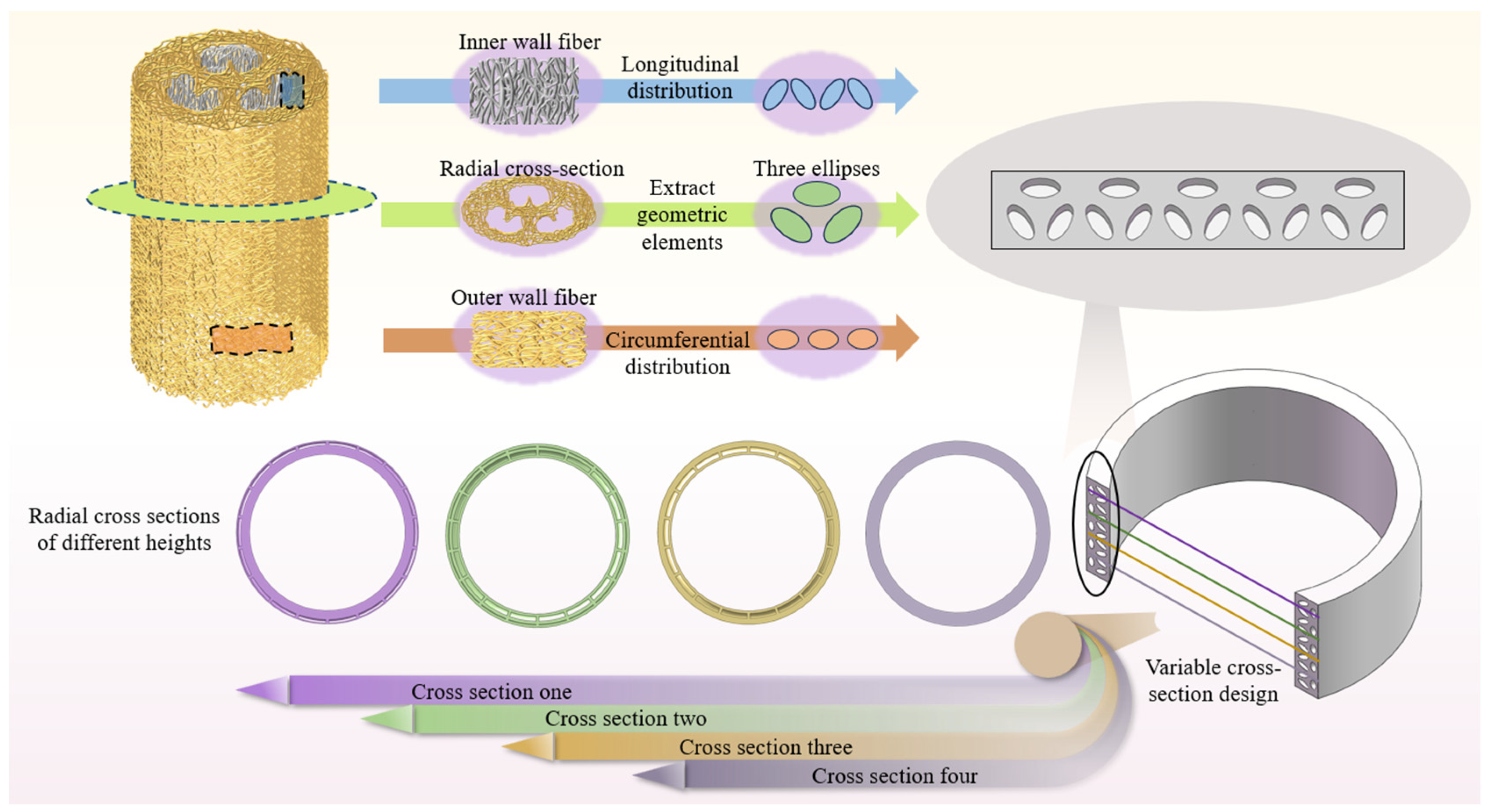
2.1. Structural Prototype Analysis of Loofahs

The bionic prototype for the design in this paper is based on the structure of loofah. As the luffa fruit ripens, it undergoes drying and dehydration, developing a unique spatial network structure characterized by interdigitating fiber bundles, i.e., the structure of loofah. This structure is also referred to as loofah sponge because of its similarity to the porous structure of sponges. The macrostructure of loofah is cylindrical, with several cavities typically distributed across its cross-section to store seeds. The microscopic structure of loofah consists of multiple layers of longitudinal and transverse mesh fiber bundles, forming cavities of various sizes and shapes, along with dense holes within the bundles. Depending on the fiber arrangement, a loofah sponge cylinder can be divided into four regions: an inner surface, outer surface, interlayer, and core [27]. On the inner surface, the thickest fiber bundles of the loofah run longitudinally, aligning with the internal channels, almost parallel to the loofah’s longitudinal axis [28]. On the outer surface, the thickest fiber bundles of the loofah align along the axial direction. In the interlayer region between the inner and outer surfaces, fiber bundles extend in all three directions [29]. Studies show that loofah fibers form a fiber cluster structure, with each fiber consisting of multiple microfibrils. The cell cross-section contains cavities, and the microfibrils are arranged in a helical shape [30]. These unique structural properties significantly affect the mechanical properties of loofah. Analysis of fibers from different parts of loofah reveals that fibers on the outer wall are typically longer and thinner, resulting in a compact outer portion. In contrast, fibers on the inner wall are generally shorter and thicker, leading to a sparser inner wall. The fibers between the two walls grow diffusely and spread throughout the pores. In contrast to the ring walls, the core fibers are loosely interconnected, with coarse single fibers running along the centerline of the loofah sponge. These features combine to give the loofah a gradient density and pore distribution. The specific structure of loofah is illustrated in Figure 2.

2.2. Bionic Design of Adapter Ring Structure

Studies have shown that the core fibers of loofah have a negligible effect on its overall mechanical properties. Therefore, the fiber distribution characteristics of the core are not considered in this bionic design. The shape of the internal cavity of loofah, shown in Figure 2, is elliptical and serves as the basic design element. An elliptical shape with a long diameter of 2 mm and a short diameter of 1 mm was selected, with a total of three elliptical rings arranged in the circumferential direction. The radial cross-section of the selected loofah structure contains three cavities, spaced 120° apart in the circumferential direction. The three cavity features are extracted and applied to the radial cross-section of the adapter ring. The outer ellipse is laterally distributed and removes less volume, mimicking the structural characteristics of loofah’s outer wall. The inner ellipse is longitudinally distributed, with a higher density of distribution, removing more volume, thus mimicking loofah’s interlayer structure towards the inner wall. The geometric element analysis of bionic design in this paper is as follows: the short diameters of adjacent ellipses are positioned at a 120° angle, forming a specific pattern along the axis of the ring. This elliptical pattern is evenly distributed, with a total of five groups aligned along the axis. Moreover, the design incorporates 18 additional groups arranged circumferentially through rotational cutting, creating a complex, yet regular, pattern of holes in the structure. Based on this arrangement, the porosity concentration of the biomimetic adapter ring structure is calculated to be 25%. This high porosity is a key feature of the biomimetic design, as it contributes to better energy absorption and load distribution by allowing for more extensive deformation throughout the structure. The strategically placed elliptical holes help distribute the strain more evenly, which enhances the overall stability and performance of the bearing. This arrangement ensures that the adapter ring can effectively absorb impact and cyclic loads, thus improving its durability and reducing the risk of localized failures typically seen in solid structures. A detailed schematic is shown in Figure 3. In terms of manufacturability, the biomimetic adapter ring is compatible with additive manufacturing technologies such as Selective Laser Melting (SLM) or Laser Powder Bed Fusion (LPBF). These technologies allow for precise control over the porosity geometry and spatial distribution based on digital CAD models, enabling the high-fidelity fabrication of the proposed structure.

2.3. Analysis of Energy Absorption in Bionic Structures

Under the simulation conditions and given the selection of structural steel as the model material in this paper, the bionic structure can be approximated as presenting a linear elastic response process, with the stress ( σ ) and strain ( ε σ ) relationship as [31]
σ = E ε σ
The energy absorbed in the process of impact resistance ( E a ) is the envelope area under the load-displacement curve:
E a = 0 δ s F δ d δ
In Equation (2), F is the impact force; δ is the deformation.
E a , s is the energy absorbed per unit mass of the bionic structure and is an important parameter for measuring the energy absorption capacity, which is expressed as
E a , s = E a / m h
In Equation (3), m h is the total mass of the buffer structure.
F m is the average value of the impact load during the whole impact process, and its expression is the ratio of the absorbed energy ( E a ) and the effective deformation displacement ( x ):
F m = E a / x
In Equation (4), F p is the peak load, and the porous cavity structure increases the deformation ( δ ) of the bionic structure, which leads to a greater amount of energy ( E a ) absorbed by the structure under the same load condition. In addition, since the structure adopts a porous cavity structure, the mass ( m h ) decreases, and the energy absorbed by the buffer structure per unit mass ( E a , s ) increases. Therefore, the bionic structure theoretically exhibits energy-absorbing properties.

3. Finite Element Analysis of Double-Decker Ball Bearing

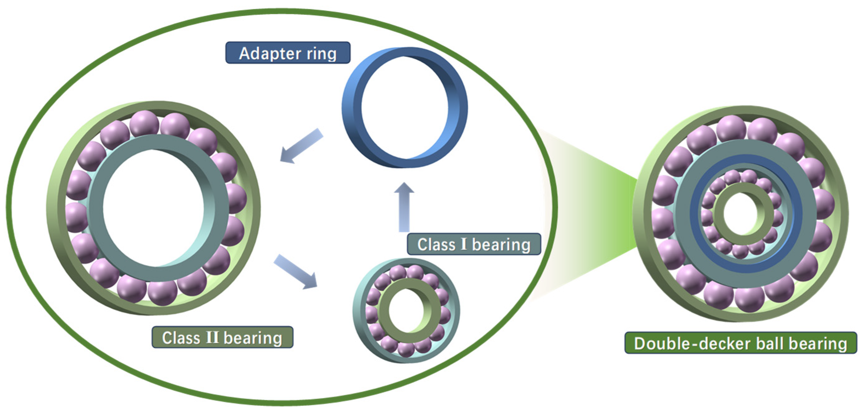
3.1. Selection of Double-Decker Ball Bearing Type

Angular contact ball bearings feature a unique structural design that causes the contact point between the bearing ball and the inner and outer raceways to form a specific angle, allowing the bearing to simultaneously support radial and axial loads in both directions. Due to their high reliability and low power consumption, angular contact ball bearings are widely used in rotating machinery systems [32]. Based on the aforementioned factors, this paper selects angular contact ball bearings for both the Class I and Class II bearings in the double-decker ball bearing design. The bearing products selected for this study are from SKF Group in Sweden, specifically the angular contact ball bearings of types 7204 ACD_P4A and 7211 ACD_P4A, which serve as the Class I and Class II bearings in the double-decker ball bearing design. The specific bearing parameters are provided in Table 1.

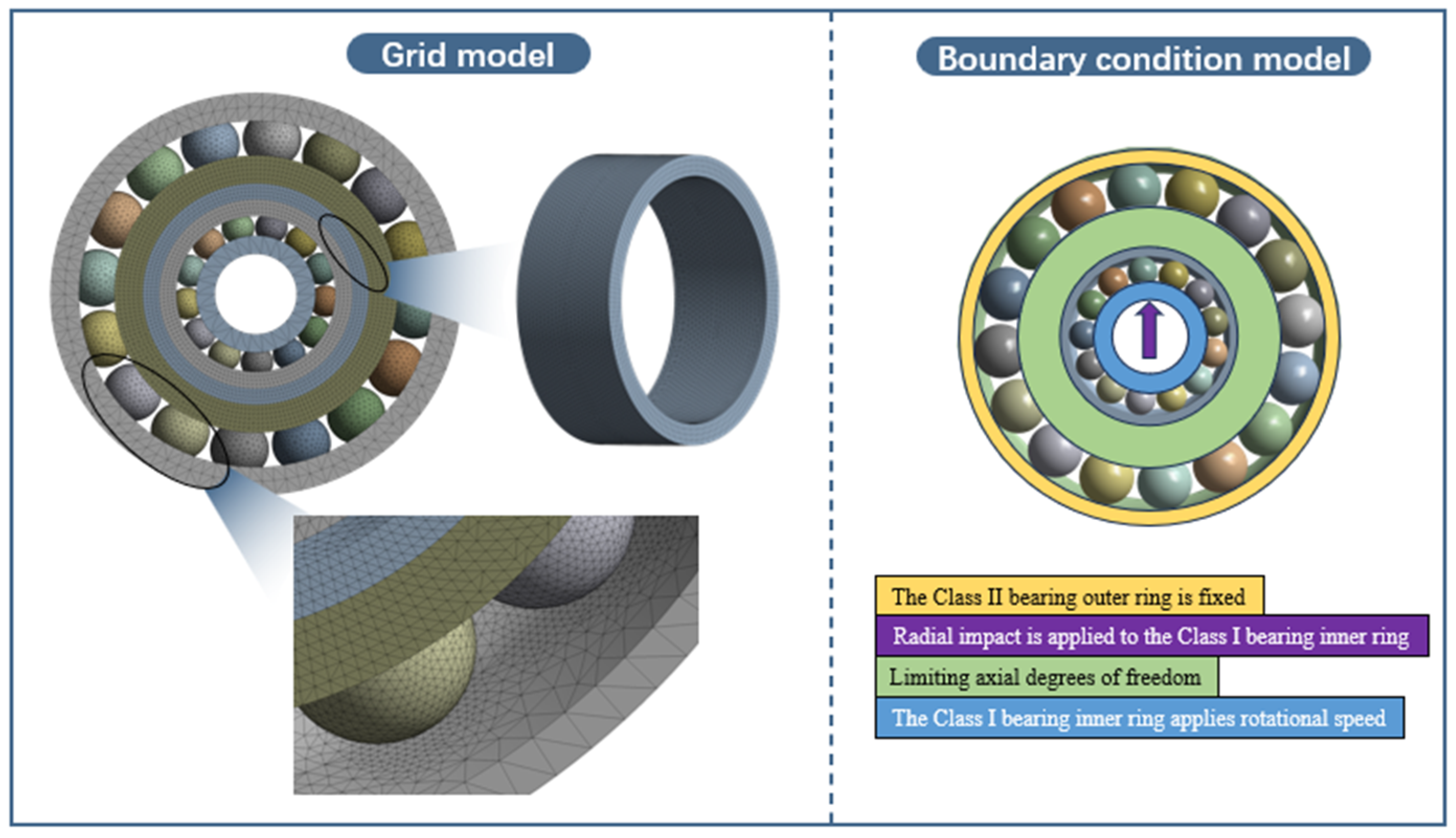
3.2. Finite Element Model Analysis Setup for Double-Decker Ball Bearing

A finite element model of a double-decker ball bearing is developed in this paper, with the Class I bearing designated as 7204, the Class II bearing designated as 7211, and the adapter ring thickness set to 4 mm. The stress concentration during bearing operation primarily occurs in the contact zone between the balls and the inner and outer raceways. Consequently, the chamfer and transition fillet of the inner and outer rings have negligible effect on the simulation results. Therefore, these features are omitted from the model to simplify the simulation calculations. Additionally, simulating bearing rotation requires numerous computational nonlinear contacts, which may result in excessive computation and hinder convergence. To reduce the computational load, the bearing model omits the cage structure, thereby reducing the number of contact pairs. The three-dimensional model of the double-decker ball bearing is imported into finite element analysis software, where contact pairs between the bearing balls and the inner and outer raceways are established for each stage, with frictional contact defined. The friction factor is set to 0.001 to simplify calculations. In this simulation, since the focus of this study is on the structural response rather than the energy dissipation mechanism, it is assumed that a low friction coefficient (CoF = 0.001) is applied at the contact interface under ideal lubrication conditions. By setting such a low friction coefficient, the model assumes that the primary interaction at the contact interface is rolling contact, rather than the typical sliding contact under ideal lubrication conditions. However, under real-world dynamic or impact loading conditions, especially in angular contact ball bearings, sliding contact is inevitable. Even with lubricants containing anti-wear additives, the effective friction coefficient under actual conditions typically rises to around 0.1. This assumption isolates the deformation effects of the structure under impact loading, avoiding the complexity of frictional losses. The adapter ring is connected to the outer ring of the Class I bearing and the inner ring of the Class II bearing through an interference fit, forming the central raceway of the double-decker ball bearing. The adapter ring is set as a bonded contact with the Class I bearing outer raceway and the Class II bearing inner raceway. The selected mesh type is tetrahedral, which meets the quality requirements. The aspect ratio of most of the meshes is below 5, and the Jacobian parameter is around 1. For the finite element model of the double-layer solid adapter ring ball bearing, a total of 1,137,122 nodes and 777,779 elements were created. The finite element model of the biomimetic adapter ring for the double-decker ball bearing was created with 1,373,089 nodes and 927,027 elements. The contact area between the bearing balls and the raceways was refined, with the mesh size at the contact surface between the Class II bearing balls and raceways set to 0.8 mm and the mesh size at the contact surface between the Class I bearing balls and raceways set to 0.6 mm. The mesh size for the adapter ring is 1 mm. The overall mesh, contact surface mesh, and adapter ring mesh divisions, as well as the application of boundary conditions, are shown in Figure 4.
AISI 52100 is a high-carbon chromium alloy steel known for its excellent hardness, wear resistance, and ability to withstand high mechanical stresses. Due to its widely recognized performance in bearing applications, AISI 52100 steel was chosen as the material for the finite element analysis simulation in this study. Its superior properties make it particularly well suited for simulating bearing performance under dynamic loading conditions. The specific material parameters are provided in Table 2. In this study, the simulation material (AISI 52100) was modeled as a linear elastic material in the finite element analysis, without introducing elastoplastic behavior or yield criteria. The simulation setup was intended to simplify the analysis process, focusing on comparing the overall mechanical response trends of different adapter ring structures under impact loading, rather than simulating local material yielding or failure behavior. Due to the linear elastic assumption, even if the local contact stress exceeds the typical yield strength of AISI 52100, the simulation still calculates the response elastically, and thus, plastic deformation or residual deformation phenomena are not represented.
The applied boundary conditions and loads are as follows:
(1)
Constrain the degrees of freedom of the nodes on the outer surface of the outer ring of the Class II bearing in all directions.
(2)
Constrain the axial translational degrees of freedom of the bearing balls and raceways in the Class I bearing, bearing balls and inner raceway in the Class II bearing, and the adapter ring.
(3)
Release the radial translational degrees of freedom of the bearing balls and raceways in the Class I bearing, bearing balls and inner raceway in the Class II bearing, and the adapter ring.
(4)
Apply a rotational speed on the inner surface of the inner ring of the Class I bearing, and apply an impact acceleration in the positive z-axis direction on the inner surface of the inner ring of the Class I bearing.
This study conducts a simulation analysis of impact accelerations at levels of 100, 200, 300, 400, and 500 mm/s2 under rotational speeds of 1000, 1500, 2000, 2500, and 3000 rpm. In standard impact resistance evaluations, external shock excitations are typically idealized into simplified waveforms such as the half-sine, double half-sine, sine, triangular, and double-triangular pulses [33]. In the present analysis, a post-peak sawtooth waveform is selected due to its distinct characteristics and practical advantages. Post-peak sawtooth pulses are widely used in various engineering domains, particularly in experimental scenarios that demand precise shock reproduction, such as in aerospace engineering, mechanical testing, and electronic component validation. Unlike conventional waveforms, the post-peak sawtooth pulse exhibits a sharply defined peak followed by an abrupt descent. This steep waveform transition intensifies the shock loading effect, inducing significant stress within a very short duration. Such dynamic features make it particularly effective in simulating high-intensity impact conditions. Moreover, the post-peak sawtooth waveform offers high repeatability and ease of implementation in laboratory environments. With the aid of appropriate pulse shaping devices, it can be reliably generated to mimic real-world impact scenarios. For these reasons, the post-peak sawtooth pulse is adopted as the excitation input in this study, as illustrated in Figure 5.
This study focuses on the double-decker ball bearing and develops a finite element model for its analysis. This paper examines the deformation, equivalent force, equivalent strain, contact stress, and safety coefficient of the bearing’s inner ring under varying impact accelerations and rotational speeds. Two bearing structures are considered: the traditional Solid Bearing Structure (SBS) and the Biomimetic Bearing Structure (BBS). We calculated that, under one of the working conditions, the radial impact load was equivalent to 1200 N. Under the static analysis, the finite element simulation obtained a maximum contact stress of 7774 MPa, and the theoretical calculation of the maximum Hertz stress was 7672.92 MPa. The calculated values were similar to the simulation results. The correctness of the simulation has been validated.

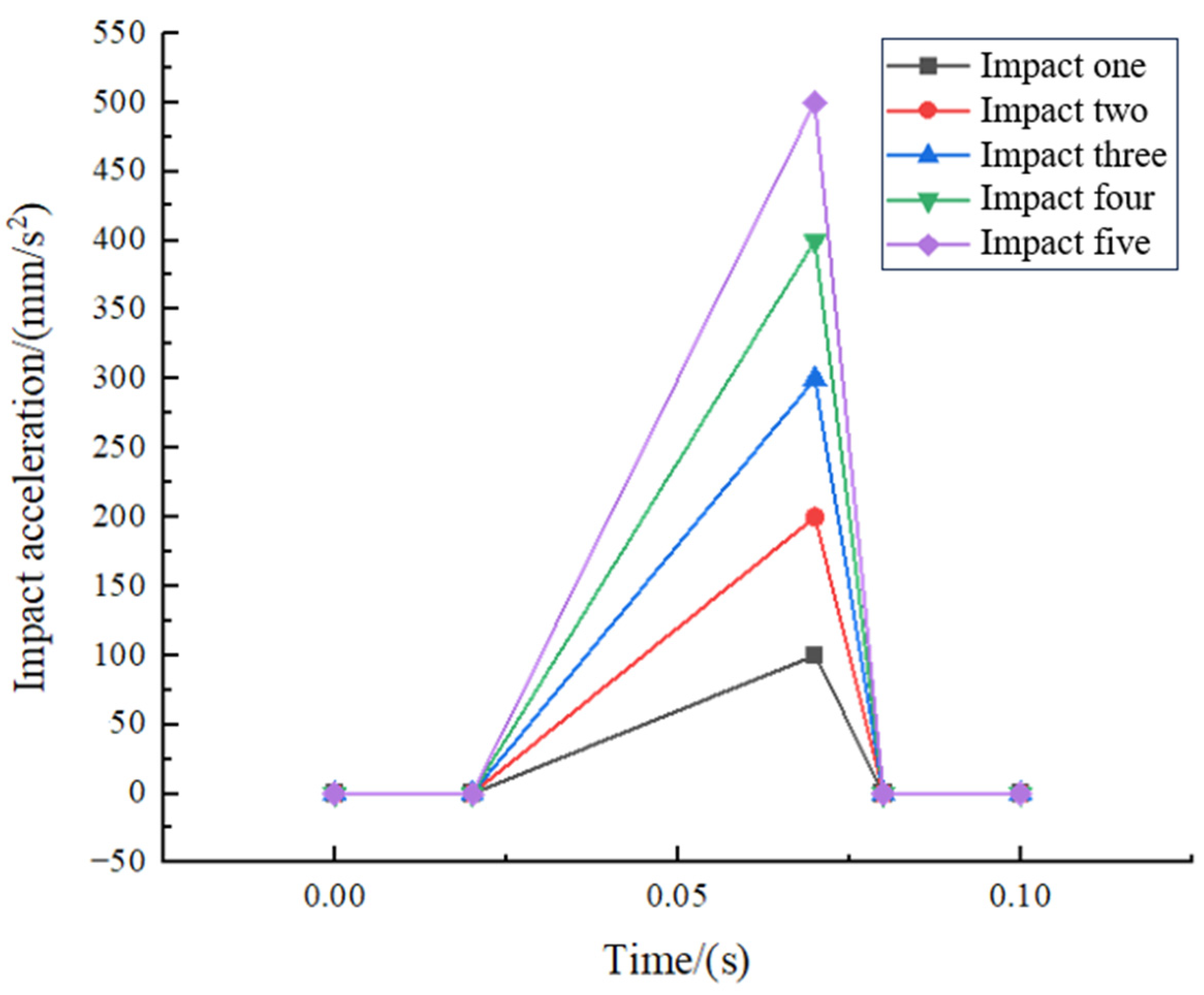
3.3. Simulation Result Analysis

This paper presents simulations of solid adapter ring structure double-decker ball bearings and bionic loofah adapter ring structure double-decker ball bearings at speeds ranging from 1000 rpm to 3000 rpm. The specific simulation results are presented in box-and-whisker plots for further analysis. In the box plots, the same color indicates the distribution of resultant response data across the 1000 to 3000 rpm range under identical shock excitation conditions for both structures.

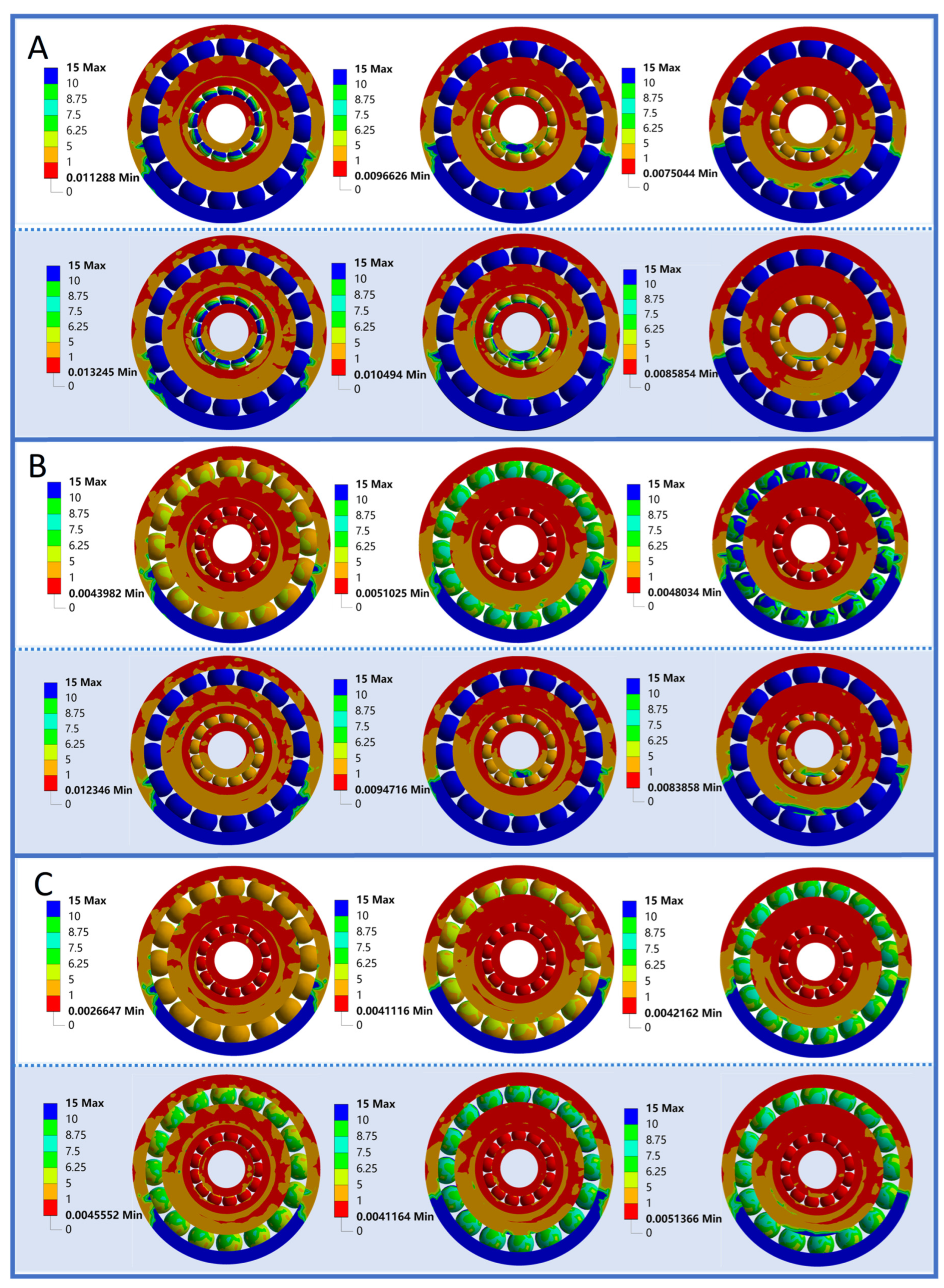
3.3.1. Deformation Analysis

The displacement data analysis of the simulation results is shown in Figure 6. The displacement in Figure 6 reflects the overall displacement response of the model under impact loading. It is important to note that this displacement includes not only the internal elastic deformation of the structure but also the rigid body motion caused by impact and rotation, particularly the rigid body displacement in the free end or partially constrained regions. Specifically, due to the presence of partially unconstrained boundary regions in the simulation, a certain degree of overall drift or displacement occurs during the impact loading process. This overall motion is not equivalent to structural failure or material yielding, but it is included in the deformation calculation, which leads to larger numerical results in the simulation.
By comparing the responses of the two structures, it can be observed that the free end displacement response of the SBS structure is larger, with a more significant overall displacement. This indicates that its structural stiffness is lower and cannot effectively suppress the rigid body motion caused by impact. In contrast, the BBS structure demonstrates better displacement suppression, with a more optimized stiffness transmission path. At low impact accelerations (100 mm/s2 and 200 mm/s2), the displacement of the BBS structure is significantly smaller than that of the SBS. At moderate impact accelerations (300 mm/s2 and 400 mm/s2), the displacement of the SBS structure is larger, while the displacement of the BBS is smaller. At high impact acceleration (500 mm/s2), the displacement of both the SBS and BBS structures decreases slightly. Overall, the BBS structure has a better ability to suppress impact compared to the SBS structure, although the variability and fluctuation in displacement responses are greater.
In this study, the micro-deformation simulation results of the double-decker ball bearing structure under specific working conditions are presented, with the deformation contour map shown in Figure 7. In general, the deformation of the SBS structure is larger than that of the BBS structure, effectively confirming the superior deformation resistance of the BBS structure. As shown in Figure 7, the maximum deformation initially occurs at the class Ⅰ bearing ball. As the impact load increases, the maximum deformation shifts to the contact area between the class Ⅰ bearing ball and the class Ⅰ bearing inner ring raceway. This phenomenon occurs earlier in the BBS structure compared to the SBS structure. Additionally, the BBS structure, through the larger deformation of the biomimetic adapter ring, adjusts the overall structure to distribute the deformation more evenly. This results in a more uniform deformation distribution throughout the entire double-decker ball bearing structure, facilitating the regulation of overall deformation and the reduction in peak deformation values.

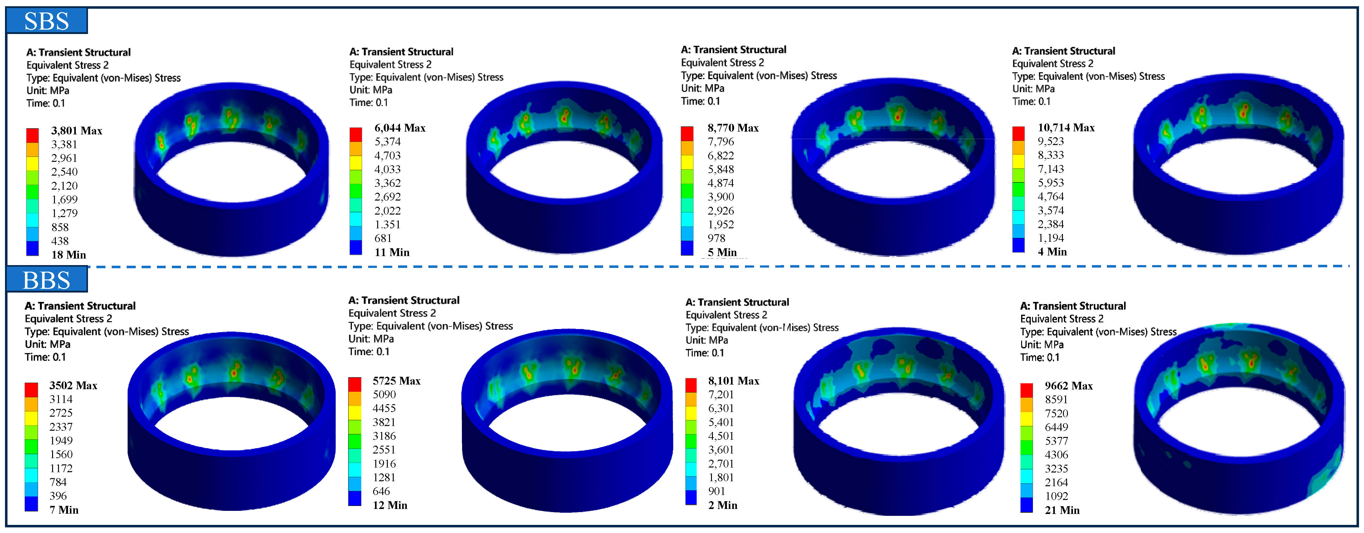
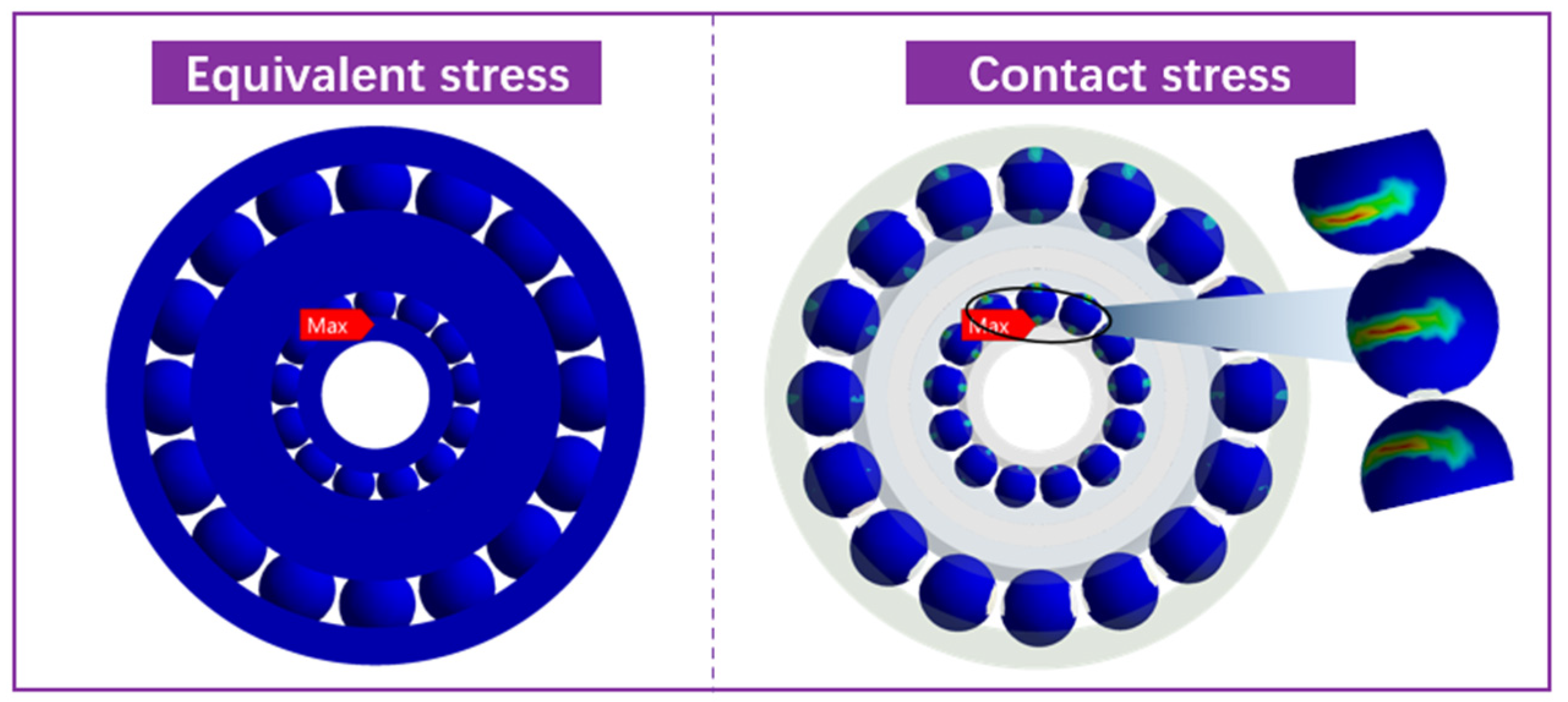
3.3.2. Equivalent Stress Analysis

As shown in Figure 8, there is a notable difference between the SBS and BBS structures under varying impact accelerations. The SBS structure exhibits higher equivalent force, particularly at low impact accelerations (100 mm/s2 and 200 mm/s2). As the impact acceleration increases, the equivalent force decreases gradually and stabilizes at 500 mm/s2. In contrast, the BBS structure exhibits lower and more concentrated equivalent force, especially at high impact accelerations (400 mm/s2 and 500 mm/s2), demonstrating better stability, consistency, and fewer outliers. The BBS structure exhibits lower equivalent stress in the same region. This reduction in stress is due to the biomimetic design, which promotes improved stress distribution, helping to more evenly spread the stress across the bearing. This reduces the likelihood of high localized stress and enhances the overall durability of the bearing. These results indicate that, compared to the traditional SBS structure, the BBS design not only improves load distribution but also provides better performance in terms of reducing high stress concentrations.
Under radial impact loading, a detailed evaluation of the stress distribution in the outer ring of the Class I bearings was conducted, as shown in Figure 9. The finite element analysis results indicate that the stress is concentrated in various regions of the bearing outer ring; however, no distinct hook stress distribution was observed, which is typically associated with high localized stress gradients at geometric corners or abrupt structural features. Instead, the maximum stress was found near the contact area between the bearing and the adjacent surfaces, rather than at structural transitions or corners. This observation suggests that the outer ring design maintains smooth geometric continuity, with no apparent discontinuities, further indicating that the structure of the outer ring is robust under typical operating conditions. Additionally, as shown in Figure 9, the stress peaks in the BBS structure are significantly lower than those in the SBS structure. The BBS structure exhibits a more uniform internal load distribution, with a weaker tendency for localized stress concentration compared to the SBS structure.
Based on the simulation results of the equivalent stress in the inner ring of the Class I bearing, as shown in Figure 10, it is clear that the maximum stress occurs at the contact point between the inner ring and the bearing ball. The finite element analysis indicates that the SBS structure exhibits higher stress values compared to the BBS structure. Specifically, in the contact area, the SBS structure shows greater localized stress, suggesting a higher risk of material fatigue or failure at these points under dynamic loading conditions.

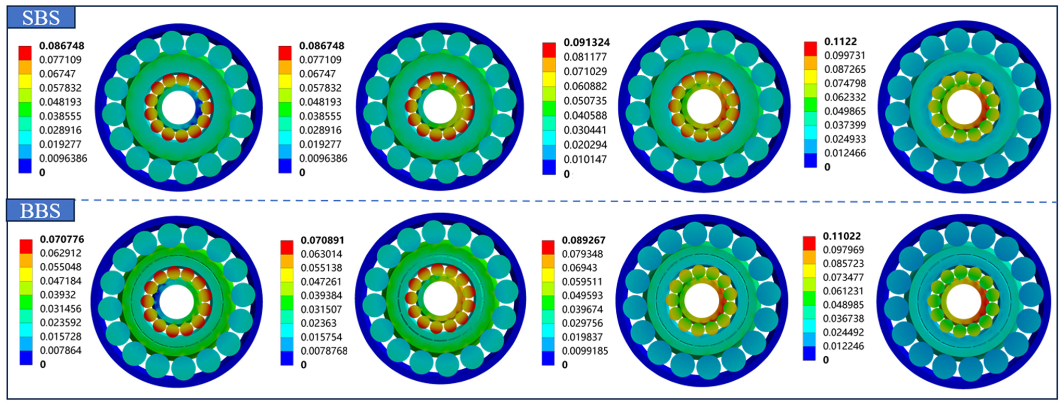
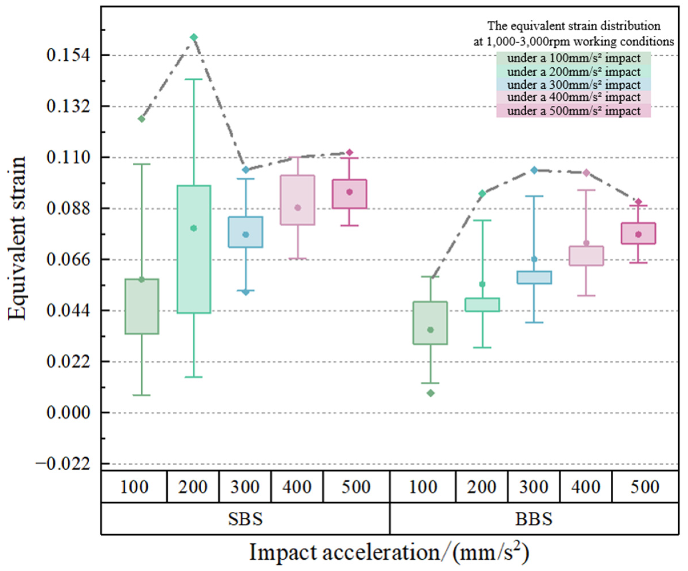
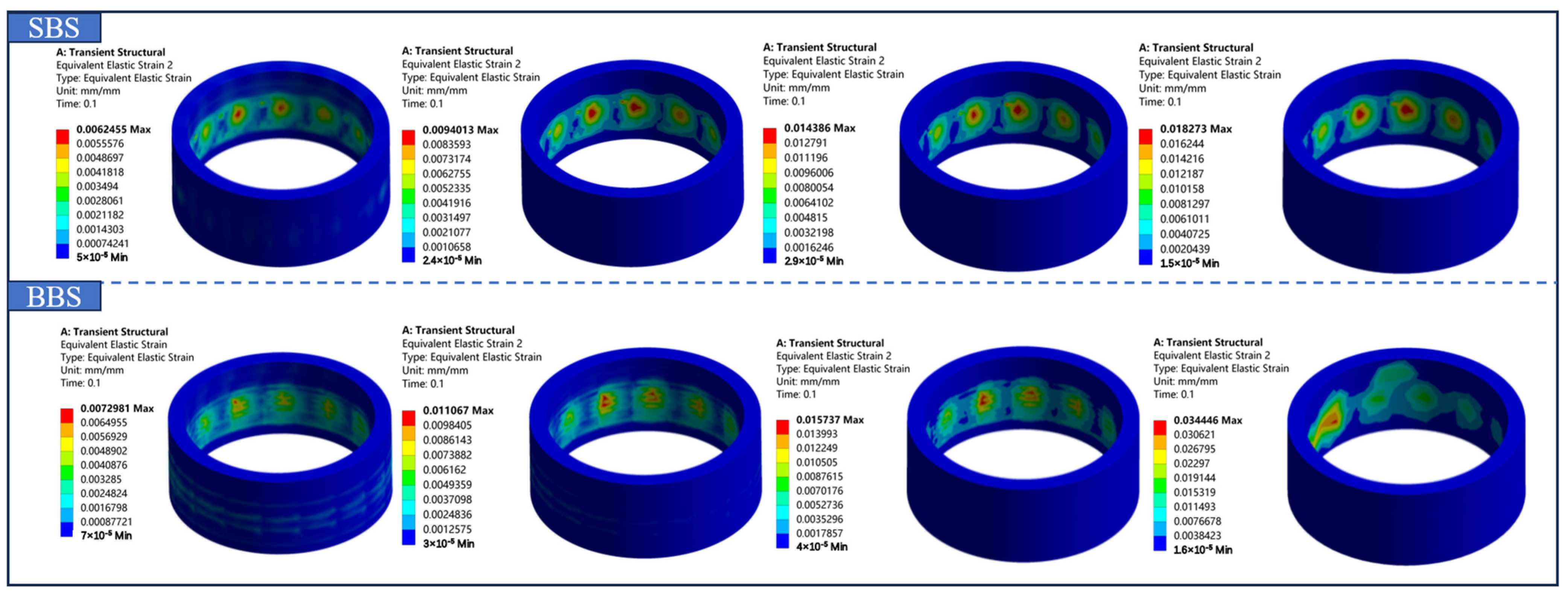
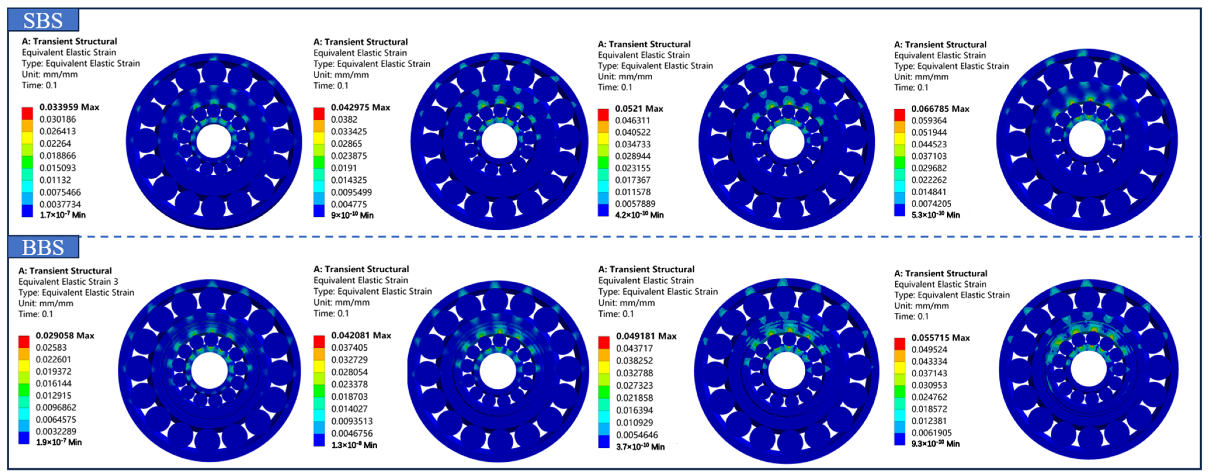
3.3.3. Equivalent Strain Analysis

As shown in Figure 11, the distribution trend of equivalent strain for both SBS and BBS structures under varying impact accelerations highlights the differences in their deformation performance. Overall, the equivalent strain of the SBS structure is higher than that of the BBS structure, with larger deformation under low impact accelerations (100 mm/s2 and 200 mm/s2), particularly peaking at 200 mm/s2. However, it also shows greater dispersion and instability. As the impact acceleration increases to the medium range (300 mm/s2 and 400 mm/s2), the equivalent strain of SBS gradually decreases, the distribution range narrows, and the deformation becomes more consistent. At high impact acceleration (500 mm/s2), the equivalent strain of SBS rises slightly, but the distribution becomes more concentrated, and performance stability improves. In contrast, the equivalent strain of the BBS structure is smaller than that of the SBS at all impact accelerations. The strain distribution is more concentrated and less discrete, particularly at high impact accelerations (e.g., 500 mm/s2), demonstrating better stability and consistency. Therefore, the BBS structure is better suited for applications requiring stricter deformation control and stability.
The strain contour maps for the adapter ring structure under specific working conditions are shown in Figure 12, illustrating the deformation distribution of both the solid and biomimetic adapter rings. It is clear that the deformation distribution of the biomimetic adapter ring is more uniform compared to the solid adapter ring, which displays a more concentrated deformation pattern. In the solid adapter ring, specific areas exhibit higher strain, which can lead to localized stress concentrations and potentially cause material failure or fatigue over time. On the other hand, the biomimetic adapter ring distributes the deformation more evenly across its structure, effectively minimizing the risk of such localized failure. Moreover, the strain values of the biomimetic adapter ring are slightly higher than those of the solid adapter ring. This indicates that the biomimetic design allows for a more extensive deformation, which is spread uniformly over the surface. This characteristic enables the biomimetic adapter ring to absorb and dissipate energy more efficiently, enhancing its performance by improving load distribution and reducing stress concentrations. While the strain is higher, the biomimetic adapter ring offers better overall stability, energy absorption, and durability, making it a more reliable choice for bearing applications. In summary, although the biomimetic adapter ring experiences slightly higher strain, its more uniform deformation distribution contributes to improved bearing stability, energy absorption, and overall performance.
Figure 13 shows the equivalent elastic strain distribution contour maps for two different adapter ring structures, SBS and BBS, under different impacts at the same rotational speed. The image illustrates the deformation distribution of the entire bearing structure under specific loading conditions. The SBS structure exhibits more localized deformation, with deformation concentrated in specific areas. This indicates that the solid structure may experience more concentrated stress points, which could potentially lead to failure in these regions under high loads. In contrast, the BBS structure shows a more uniform strain distribution, helping to spread the deformation across the entire structure. This potentially improves the overall stability and performance under dynamic loading conditions. The BBS structure performs better in uniformly distributing strain across the entire surface, which leads to improved performance, especially under high or repetitive loads. In summary, compared to the SBS structure, the BBS structure demonstrates better deformation distribution and greater overall stability. This suggests that the biomimetic design offers advantages in energy absorption and load distribution, which can enhance the structural performance and lifespan of the bearing.

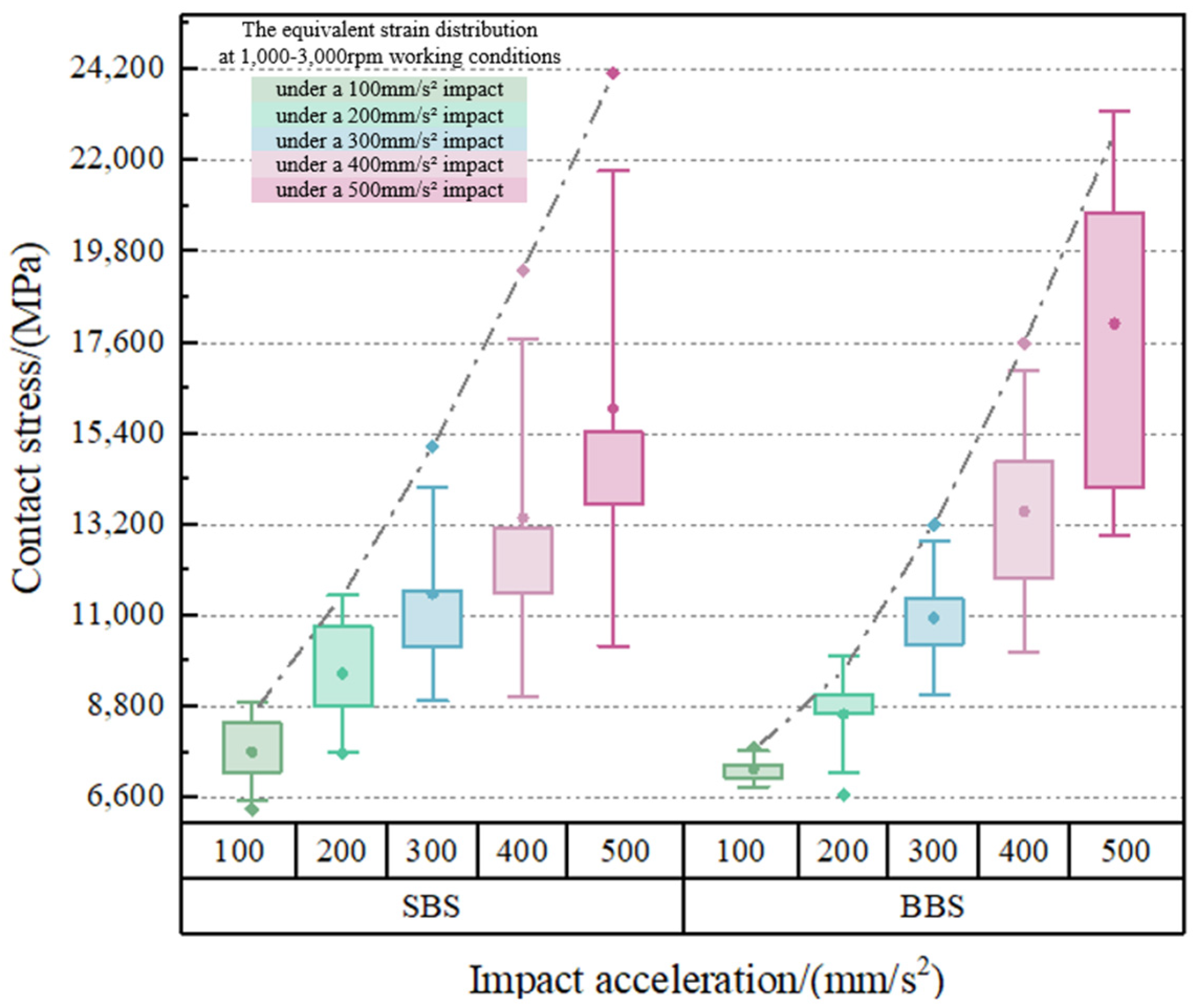
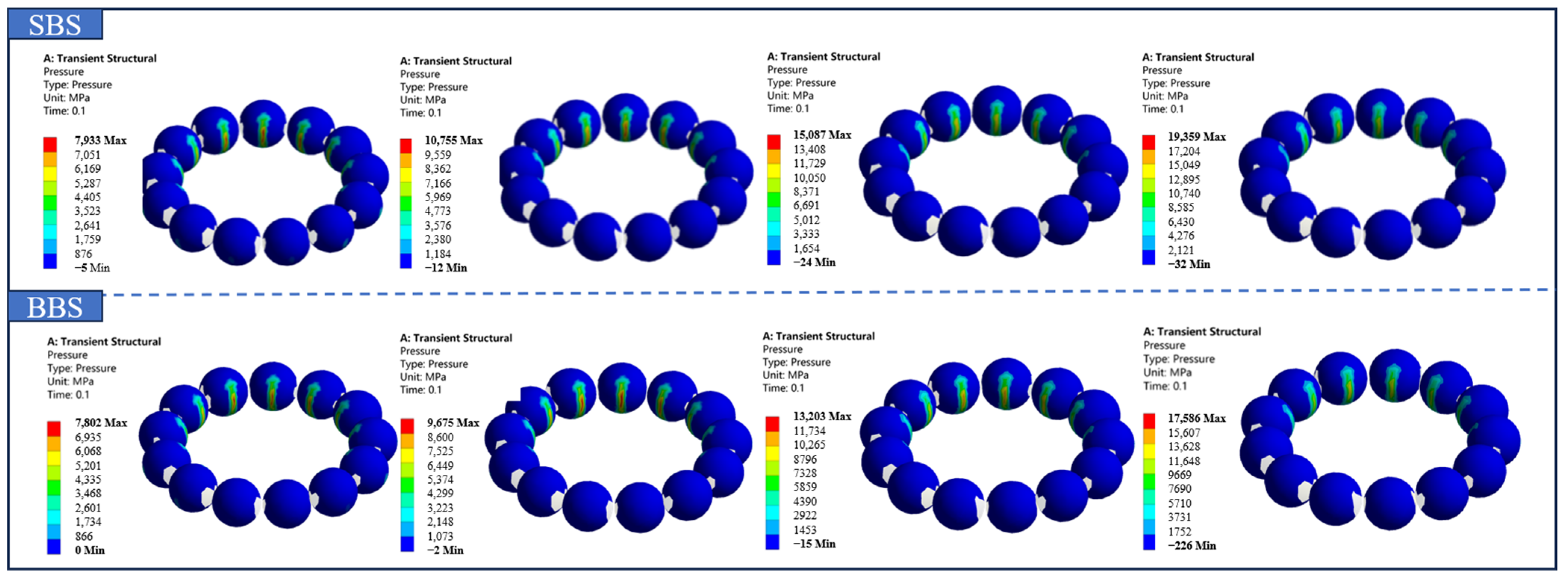
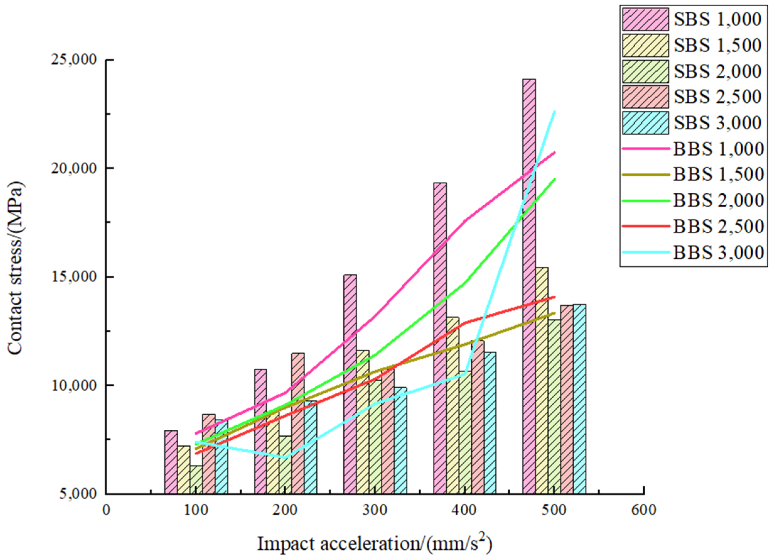
3.3.4. Contact Stress Analysis

In this contact stress simulation, the high stress values are primarily concentrated in a very small region at the contact interface, representing a numerical peak commonly observed in finite element simulations. This occurs in cases with rigid boundary settings, idealized contact stiffness, or nodes with highly concentrated mesh. Additionally, a localized mesh refinement strategy was applied in the contact region to improve the resolution of the stress distribution near the contact surface. It is important to note that, although the stress peak is high, its distribution is very limited, and it has a minimal impact on the overall force distribution trend and the comparison results of the structure.
As shown in Figure 14, the SBS and BBS structures exhibit distinct characteristics in terms of contact stress performance. As the impact acceleration increases from 100 mm/s2 to 500 mm/s2, the contact stresses of both structures increase, with the maximum contact stress of the SBS structure being consistently higher than that of the BBS structure, particularly under high impact accelerations (400 mm/s2 and 500 mm/s2). The results also show that the SBS structure has a wider stress distribution range, higher dispersion, and more outliers, suggesting a higher risk of localized failure under high-impact conditions due to greater volatility. In contrast, the contact stresses of the BBS structure are lower, with a more concentrated distribution, less dispersion, and fewer outliers, indicating higher stability and reliability. Therefore, BBS structures are preferable in scenarios that demand higher stability and reliability.
As shown in Figure 15, the maximum equivalent stress and contact stress are concentrated between the ball and the inner ring of the Class I bearing. Since the impact direction is along the positive Z-axis, both the maximum equivalent stress and contact stress occur at the contact point between the ball and the inner ring of the Class I bearing. The localized magnification of the contact stress between the inner ring and the heaviest loaded bearing ball is shown in Figure 15. Since the maximum contact stress is primarily concentrated in the Class I bearing, contact stress contour maps for the Class I bearing under specific working conditions were extracted, as shown in Figure 16. These results highlight the key differences in contact stress between the SBS and BBS structures. In the SBS structure, the maximum contact stress is concentrated at certain contact points, particularly between the bearing ball and the inner ring, with significantly higher stress values. This localized high stress is a concern because it may lead to premature wear or failure of these areas under dynamic loading conditions. However, in the BBS structure, the peak contact stress is noticeably lower than the stress levels observed in the SBS structure. This indicates that the BBS design is more effective in reducing localized contact stress. The biomimetic structure helps to diffuse stress over a larger area, preventing stress concentration and reducing the risk of material degradation. This makes the bearing more resilient to wear and more reliable over time. By lowering the peak contact stress, the BBS structure contributes to better long-term performance and extends the bearing’s lifespan, especially under high-impact and repetitive loading conditions.
As shown in Figure 17, the contact stress of the bearing decreases as the bearing speed increases. The contact stress bar chart for the SBS and the line chart for the BBS at 1000 rpm show the highest values. In contrast, the charts at 3000 rpm display the lowest values.

3.3.5. Safety Factor Analysis

The simulations conducted for the conditions of 1000 rpm, 2000 rpm, and 3000 rpm, subjected to impact accelerations of 200 mm/s2, 300 mm/s2, and 400 mm/s2, respectively, are presented in the safety factor data shown in the cloud diagrams in Figure 18. In Figure 18, panels A, B, and C correspond to the results for 1000 rpm, 2000 rpm, and 3000 rpm, respectively. The top and bottom of each panel show the results for the SBS and BBS structures, respectively. From Figure 18, it is evident that the safety factor distribution for the SBS structure varies significantly across different regions. The red region (low safety factor) is concentrated closer to the center, indicating higher stress concentrations and a potentially greater risk of failure in these areas. The blue region (high safety factor) is located in the outer ring, indicating lower stress and relatively higher safety. The red region (low safety factor) in the BBS structure is significantly reduced, particularly near the center, indicating that the improved design alleviates the stress concentration issue. The blue region (high safety factor) shows a more uniform distribution, and the overall safety factor is improved, suggesting a more balanced stress distribution after design improvements.

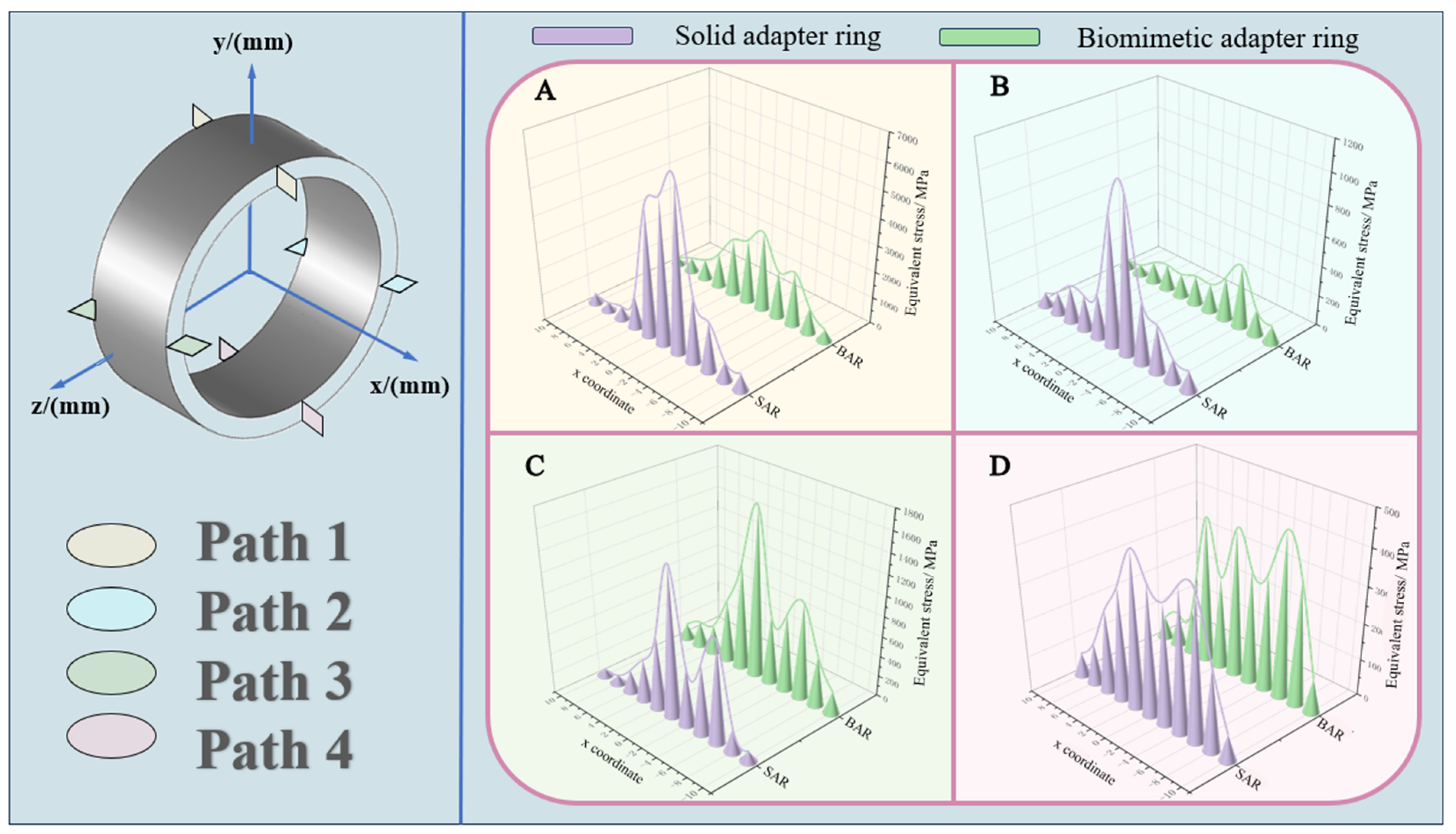
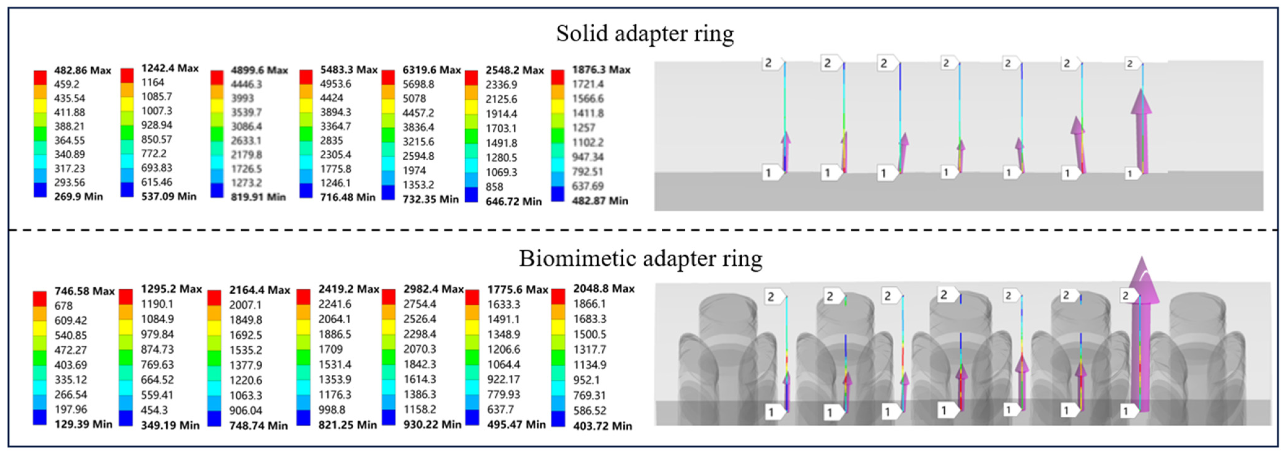
4. Bionic Loofah Adapter Ring Performance Analysis

According to the theories of material mechanics, when a homogeneous, isotropic object with a uniform cross-section is subjected to external loads, the stresses are evenly distributed across its cross-section. However, when holes are present in the cross-section, they experience dimensional changes under external loads, leading to a sharp increase in stress around the hole. The stress in regions at a certain distance from the hole decreases gradually and stabilizes, a phenomenon known as hole-induced stress concentration. The bionic loofah adapter ring structure designed in this study incorporates specific geometric features of hole structures. However, the BBS structure exhibits a less significant lagging trend compared to the SBS structure and shows some improvement. This is because the bionic structure design is inspired by the structural characteristics of loofah, with hole positions arranged to mimic those found in loofah’s natural structure.
The pore elements in this study are elliptical, inspired by the seed storage cavities within loofah. At the microscopic level, the interlocking fibers of loofah form elliptical pores. The orientation of the elliptical long axis corresponds to the growth direction of the inner, outer, and interlayer fibers of loofah. The outer wall of the adapter ring is axially aligned with the long axis of the ellipse. The inner wall of the ellipse is staggered along its long axis, with a tendency toward a radial orientation. An angle exists between the long axis of the elliptical holes near the inner wall and the loading direction of the Z-axis impact acceleration. If the long axis of the elliptical holes is perpendicular to the loading direction, stress concentrations are likely to occur around the perimeter, leading to uneven stress distribution. An angle between the two can effectively mitigate stress concentration. Additionally, multiple elliptical holes are arranged at an angle along the inner wall of the adapter ring, ensuring uniform distribution rather than isolated holes. Consequently, the material arrangement and density around each hole are reduced, enhancing the structure’s flexibility. Hole designs are prone to stress concentration, but optimizing the geometric arrangement can effectively mitigate this and promote a more uniform structure.
Figure 19 presents the stress values of local radial paths in the SBS and BBS adapter ring sections, analyzed under the working conditions of 2500 rpm and 500 mm/s2. Using the coordinate system in Figure 19 as a reference, paths 1 to 4 are defined by the following start and end coordinates: (0, 23.5) to (0, 27.5), (23.5, 0) to (27.5, 0), (−23.5, 0) to (−27.5, 0), and (0, −23.5) to (0, −27.5). The x-coordinates are chosen as −10, −8, −6, −4, −2, 0, 2, 4, 6, 8, and 10. The simulation results for the stress values along the specific paths are shown in Figure 19A–D. In Figure 19, panels A, B, C, and D represent the stress trend plots for the four paths of the adapter ring, respectively. Since the impact direction is along the positive z-axis, the maximum stress occurs at path 1, while the minimum stress occurs at path 4. The stress difference between path 1 and path 2 is significant, with the bionic adapter ring exhibiting much lower stress values than the solid adapter ring. In Figure 19, the stress trends at different depths reveal that the bionic adapter ring exhibits a gentle stress distribution along paths 1, 2, and 4, whereas the solid adapter ring shows a steeper trend. The stress trends for both rings along path 3 are similar. In Figure 20, this paper analyzes the stress distribution of the two adapter ring structures along path 1. Table 3 shows the specific values of the stress extremes. The maximum and minimum stress differences for paths 1 and 2 in the bionic adapter ring are significantly reduced compared to the solid adapter rings. For paths 3 and 4, the stress differences for both adapter rings are similar. In summary, the stress distribution of the bionic adapter ring is more uniform, effectively mitigating the effects of stress concentration on the adapter ring structure. The equivalent stress contour map for path 1 is shown in Figure 20. In both structures, the maximum equivalent stress values are relatively high. However, these stress concentrations are primarily located at the contact edge regions, heavily influenced by loading discontinuities and boundary constraints. This is a typical feature of the contact area, where stress is most intense due to abrupt changes at the boundaries, as indicated by the higher stress values in the corresponding regions of both the solid and biomimetic rings. The contact behavior of the adapter ring structure is more complex than predicted by traditional Hertzian contact theory, as it involves a combination of multi-point and surface contact characteristics. The adapter ring is not purely elastic and does not follow the simple model used in classical Hertz theory. Although higher localized stresses are observed, the biomimetic adapter ring, with its innovative design features, is able to effectively reduce peak stresses compared to the solid adapter ring. The biomimetic design optimizes load distribution and enhances the structure’s ability to absorb impact energy, resulting in lower stress values in the contact area of the biomimetic ring. The optimization results show that the biomimetic adapter ring is more effective at distributing the load. By reducing peak contact stresses, the biomimetic design minimizes the risk of material failure, providing improved durability and performance.

5. Conclusions

This paper addresses the lightweight design and shock resistance issues of double-decker ball bearings by proposing a bionic loofah-based double-decker ball bearing structure and conducting modeling and simulation under shock loading. The key findings are summarized below:
(1)
Through the combination of biomimetic porous design and solid design in this study, we successfully achieved weight reduction in the double-decker ball bearing structure. By adopting a novel biomimetic loofah structure design, the weight of the bearing adapter ring was reduced by 25.26%.
(2)
The new bearing structure under the simulation condition of 1000 rpm~3000 rpm in this paper has some improvement in the aspects of deformation, equivalent stress, equivalent strain, contact stress, and safety factor compared with the original double-decker ball bearing structure.
(3)
The maximum equivalent stress and the maximum contact stress of double-decker ball bearings appear in the contact between the inner ring of the class Ⅰ bearing and the rolling elements, and the contact stress shows a nonlinear decreasing trend with the increase in bearing speed.
(4)
Under radial impact load, the overall stress in the bionic loofah adapter ring in the axial direction first rises and then declines according to the law of distribution. Compared to the solid adapter ring structure, the overall distribution of stress in the bionic adapter ring structure is more uniform, the stress changes are smaller, and the stress concentration degree is lower.
The bionic loofah structure considered in this paper provides a theoretical basis for improving the lightweight design of double-decker ball bearings.

6. Future Work

In future research, lightweight materials such as aluminum alloys will be considered for the production of adapter rings. These aluminum alloys offer good strength, excellent corrosion resistance, and high formability. Additionally, they possess outstanding damping properties, which are crucial for reducing vibrations in mechanical systems. The low density of these materials is particularly advantageous, as it can significantly reduce the overall system mass without compromising the structural stiffness or load-bearing capacity of the adapter ring. The present simulation does not explicitly include the effects of bearing preload and thermal expansion. Bearing preload can affect the contact stiffness and initial clearance, while thermal expansion may alter the fit and contact pressure distribution. These factors are critical in real-world applications and will be considered in future studies. We will incorporate a thermomechanical coupling approach and preload modeling to enhance the accuracy and applicability of the model under operational conditions. This study analyzes the bearing’s response under impact conditions based on the assumption of ideal elasticity. However, in real engineering applications, particularly under high-load impact or extreme conditions, localized plastic deformation may occur, which would further affect the contact stress distribution. Future research could incorporate elastoplastic material models to comprehensively consider material yielding behavior and nonlinear contact mechanisms, thereby enabling a more accurate assessment of Hertzian contact stress.

Author Contributions

Writing original draft, J.H. and X.Z. (Xin Zhang); data curation, P.W. and Y.Z.; supervision, X.Z. (Xinming Zhang); methodology, J.Z., B.Z. and J.L. All authors have read and agreed to the published version of the manuscript.

Funding

This research is supported by the Jilin Natural Science Foundation of China under Contract No. 20240101103JC.

Data Availability Statement

The data used in this article may be obtained from the corresponding author upon reasonable request.

Conflicts of Interest

Authors Baoyan Zhao and Jingru Liu were employed by the company Faw Tooling Die Manufacturing Co., Ltd. The remaining authors declare that the research was conducted in the absence of any commercial or financial relationships that could be construed as a potential conflict of interest.

References

  1. Xu, F.; Ding, N. A review of bearing failure Modes, mechanisms and causes. Eng. Fail. Anal. 2023, 152, 107518. [Google Scholar] [CrossRef]
  2. Chen, R.; Li, J.; Wang, Y. Study on the Time-Varying Stiffness Characteristics of Four-Point Contact Ball Bearings. Lubricants 2025, 13, 118. [Google Scholar] [CrossRef]
  3. Li, Z.; Zhong, Z.; Zhang, Z. Rolling Bearing Dynamics Simulation Information-Assisted Fault Diagnosis with Multi-Adversarial Domain Transfer Learning. Lubricants 2025, 13, 116. [Google Scholar] [CrossRef]
  4. Anderson, W.J. Tribology for Aerospace Application; Society of Tribologists and Lubrication Engineers: Park Ridge, IL, USA, 1973; pp. 526–528. [Google Scholar]
  5. Prashad, H. A new generation double decker high precision rolling element bearing concept, development and investigations. Tribol. Trans. 2001, 44, 203–208. [Google Scholar] [CrossRef]
  6. Prashad, H. Relative comparison of stiffness and damping properties of double decker high precision and conventional rolling-element bearings. Tribol. Int. 2002, 35, 265–269. [Google Scholar] [CrossRef]
  7. Prashad, H. Experimental evaluation of the stress distribution on the outer surface of the outer race of conventional and double decker high precision bearings. Tribotest 2003, 9, 249–260. [Google Scholar] [CrossRef]
  8. Prashad, H. A theoretical approach to evaluating the performance characteristics of double-decker high precision bearings. Tribotest 2004, 10, 251–263. [Google Scholar] [CrossRef]
  9. Prashad, H. Centrifugal forces on double decker high precision and conventional ball bearings. J. Inst. Eng. India Part C Mech. Eng. Div. 2005, 86, 109. [Google Scholar]
  10. Zhu, Y.; Xu, L. Mechanical research of double-decker ball bearing. J. Aerosp. Power 2011, 26, 1914–1920. [Google Scholar]
  11. Zhu, Y.; Zhang, Y.; Jin, C. Research on the mechanical properties of a new “I” type double-decker ball bearing. J. Tribol. 2016, 138, 021102. [Google Scholar] [CrossRef]
  12. Zhu, Y.; Jin, C.; Xu, L. Dynamic responses of rotor drops onto double-decker catcher bearing. Chin. J. Mech. Eng. 2013, 26, 104–113. [Google Scholar] [CrossRef]
  13. Zhu, Y.; Zheng, Z. The use of double-decker catcher bearing with face-to-face installed inner layer bearings. Mod. Phys. Lett. B 2017, 31, 1740012. [Google Scholar] [CrossRef]
  14. Jin, C.; Zhu, Y.; Xu, L. The thermodynamic properties of a new type catcher bearing used in active magnetic bearings system. Appl. Therm. Eng. 2015, 82, 253–263. [Google Scholar] [CrossRef]
  15. Hu, J.; Qiao, X.; Lv, Q. Research on a numerical calculation for ball bearings based on a finite initial value search method. Math. Probl. Eng. 2021, 2021, 6617131. [Google Scholar] [CrossRef]
  16. Hu, J.; Zhang, B.; Zhang, X. Study on speed transfer characteristics of double-deck ball bearing based on generalized four-terminal parameter method. Nonlinear Dyn. 2022, 110, 3273–3302. [Google Scholar] [CrossRef]
  17. Pape, F.; Coors, T.; Poll, G. Investigations on tailored forming components as tribologically loaded machine elements. Forsch. Ingenieurwesen Eng. Res. 2018, 82, 311–318. [Google Scholar] [CrossRef]
  18. Coors, T.; Mildebrath, M.; Büdenbender, C. Investigations on tailored forming of AISI 52100 as rolling bearing raceway. Metals 2020, 10, 1363. [Google Scholar] [CrossRef]
  19. Zheng, L.; Zuo, Y.; Li, X. Biomimetic swallow nest structure: A lightweight and high-strength thermal insulation material. ACS Nano 2022, 16, 8116–8127. [Google Scholar] [CrossRef]
  20. Huang, Z.; Li, X.; Guan, X. Biomimetic lightweight design of legged robot hydraulic drive unit shell inspired by geometric shape of fish bone rib structure. J. Bionic Eng. 2024, 21, 1238–1252. [Google Scholar] [CrossRef]
  21. Zou, M.; Xu, S.; Wei, C. A bionic method for the crashworthiness design of thin-walled structures inspired by bamboo. Thin-Walled Struct. 2016, 101, 222–230. [Google Scholar] [CrossRef]
  22. Yang, X.; Xi, X.; Pan, Q. In-plane dynamic crushing of a novel circular-celled honeycomb nested with petal-shaped mesostructure. Compos. Struct. 2019, 226, 111219. [Google Scholar] [CrossRef]
  23. Chen, J.; Zhang, X.; Okabe, Y. Beetle elytron plate and the synergistic mechanism of a trabecular-honeycomb core structure. Sci. China Technol. Sci. 2019, 62, 87–93. [Google Scholar] [CrossRef]
  24. Jiang, B.; He, C.; Zhao, N. Ultralight metal foams. Sci. Rep. 2015, 5, 13825. [Google Scholar] [CrossRef]
  25. Pape, F.; Noelke, C.; Kaierle, S. Influence of foaming agents on laser based manufacturing of closed-cell Ti foam. Procedia Mater. Sci. 2014, 4, 97–102. [Google Scholar] [CrossRef]
  26. Yu, C.; Xu, L.; Yu, X. Research on the mechanical properties of “Z” type double-decker ball bearings. J. Tribol. 2014, 136, 011102. [Google Scholar] [CrossRef] [PubMed]
  27. Shen, J.; Xie, Y.; Huang, X. Mechanical properties of luffa sponge. J. Mech. Behav. Biomed. Mater. 2012, 15, 141–152. [Google Scholar] [CrossRef]
  28. Chen, Q.; Shi, Q.; Gorb, S. A multiscale study on the structural and mechanical properties of the luffa sponge from Luffa cylindrica plant. J. Biomech. 2014, 47, 1332–1339. [Google Scholar] [CrossRef] [PubMed]
  29. Shen, J.; Xie, Y.; Huang, X. Behaviour of luffa sponge material under dynamic loading. Int. J. Impact Eng. 2013, 57, 17–26. [Google Scholar] [CrossRef]
  30. Zampieri, A.; Mabande, G.; Selvam, T. Biotemplating of Luffa cylindrica sponges to self-supporting hierarchical zeolite macrostructures for bio-inspired structured catalytic reactors. Mater. Sci. Eng. C 2005, 26, 130–135. [Google Scholar] [CrossRef]
  31. Chen, B.; Zou, M.; Liu, G. Experimental study on energy absorption of bionic tubes inspired by bamboo structures under axial crushing. Int. J. Impact Eng. 2018, 115, 48–57. [Google Scholar] [CrossRef]
  32. Zhang, J.; Fang, B.; Hong, J. Effect of preload on ball-raceway contact state and fatigue life of angular contact ball bearing. Tribol. Int. 2017, 114, 365–372. [Google Scholar] [CrossRef]
  33. Zhang, X.; Liu, J.; Pan, J. Review on anti-shock criteria for equipments in some primary navy countries. J. Ship Mech. 2011, 15, 1322–1334. [Google Scholar]
Figure 1. Schematic diagram of “I” type double-decker ball bearing structure.
Lubricants 13 00205 g001
Figure 2. A schematic diagram of the structure of loofah.
Lubricants 13 00205 g002
Figure 3. Schematic structure of bionic loofah adapter ring.
Lubricants 13 00205 g003
Figure 4. Schematic diagram of mesh and boundary conditions for double-decker ball bearing.
Lubricants 13 00205 g004
Figure 5. Schematic diagram of impact excitation.
Lubricants 13 00205 g005
Figure 6. Displacement result response.
Lubricants 13 00205 g006
Figure 7. A schematic diagram of the deformation distribution of the double-decker ball bearing under different impacts at 1000 rpm.
Lubricants 13 00205 g007
Figure 8. Equivalent stress result response.
Lubricants 13 00205 g008
Figure 9. A schematic diagram of the stress distribution on the outer ring of the Class I bearing under different impacts at 1000 rpm.
Lubricants 13 00205 g009
Figure 10. A schematic diagram of the stress distribution on the inner ring of the Class I bearing under different impacts at 1000 rpm.
Lubricants 13 00205 g010
Figure 11. Equivalent strain result response.
Lubricants 13 00205 g011
Figure 12. A schematic diagram of the strain distribution of the adapter ring under different impacts at 1000 rpm.
Lubricants 13 00205 g012
Figure 13. A schematic diagram of the strain distribution of the double-decker ball bearing under different impacts at 1000 rpm.
Lubricants 13 00205 g013
Figure 14. Contact stress result response.
Lubricants 13 00205 g014
Figure 15. Equivalent stress and contact stress maps of the double-decker ball bearing.
Lubricants 13 00205 g015
Figure 16. A schematic diagram of the contact stress of the Class I bearing under different impacts at 1000 rpm.
Lubricants 13 00205 g016
Figure 17. Contact stress simulation data schematic.
Lubricants 13 00205 g017
Figure 18. Safety factor result response: (A) At a working condition of 1000 rpm; (B) At a working condition of 1000 rpm; (C) At a working condition of 1000 rpm.
Lubricants 13 00205 g018
Figure 19. The stress analysis of the local path of the bionic adapter ring: (A) Path 1; (B) Path 2; (C) Path 3; (D) Path 4.
Lubricants 13 00205 g019
Figure 20. A schematic diagram of the stress distribution of the adapter ring of path 1.
Lubricants 13 00205 g020
Table 1. Geometric dimensions of double-decker ball bearings.
ParametersBearing Type
72047211
Number of spheres Z1316
Breadth B/mm1421
Sphere diameter Dw/mm7.93814.288
Inside diameter d/mm2055
Outside diameter D/mm47100
Contact angle α/°2525
Table 2. AISI 52100 parameters.
MaterialDensity/(kg/m3)Modulus of Elasticity/GPaPoisson’s Ratio
AISI 5210078102000.3
Table 3. The stress ranges before and after the design of the adapter ring.
Path 1Path 2Path 3Path 4
Stress range of solid adapter ring/MPa6009.75956.441397.08361.656
Stress range of biomimetic adapter ring/MPa2742.55355.91516.44388.258
Disclaimer/Publisher’s Note: The statements, opinions and data contained in all publications are solely those of the individual author(s) and contributor(s) and not of MDPI and/or the editor(s). MDPI and/or the editor(s) disclaim responsibility for any injury to people or property resulting from any ideas, methods, instructions or products referred to in the content.

