Article

Discussion on the Non-Linear Stability of Short Hydrodynamic Bearings by Applying Rabinowitsch Fluid Model

1
School of Mechanical Engineering, Yellow River Conservancy Technical Institute, Kaifeng 475004, China
2
State Key Laboratory of Intelligent Manufacturing Equipment and Technology, Huazhong University of Science and Technology, Wuhan 430074, China
3
College of Mechanical and Power Engineering, China Three Gorges University, Yichang 443002, China
*
Author to whom correspondence should be addressed.
Lubricants 2025, 13(5), 194; https://doi.org/10.3390/lubricants13050194
Submission received: 22 March 2025 / Revised: 18 April 2025 / Accepted: 22 April 2025 / Published: 23 April 2025
(This article belongs to the Special Issue Nonlinear Dynamics of Frictional Systems)

Abstract

:
Using the Rabinowitsch fluid model, the effects of dilatant fluids (a non-Newtonian factor less than 0) and pseudo-plastic fluids (a non-Newtonian factor greater than 0) on the non-linear stability of hydrodynamic journal bearings is discussed. The modified Reynolds equation is solved by the small perturbation method, and the stiffness and damping coefficients and threshold speed of hydrodynamic bearings are obtained. Through the fourth-order Runge–Kutta method, the trajectory of the journal center is traced and the non-linear stability boundary of hydrodynamic bearings with different non-Newtonian lubricants could be confirmed. The results show that the dilatant fluids could increase the threshold speed and enlarge the non-linear stability region of the hydrodynamic bearing, while the influence of pseudo-plastic fluids is positive. And for the lubricants with a larger non-Newtonian factor, the effect is more obvious. It could be confirmed that the stability of hydrodynamic bearings lubricated with dilatant fluids is better than that of bearings with Newtonian and pseudo-plastic lubricants. The results illustrate that selecting a more appropriate lubricant can enhance the stability of hydrodynamic bearings.

1. Introduction

The hydrodynamic journal bearing is a key support part in many rotating machines, and the rotating and static parts of machines are totally isolated by the thin oil film. The load capacity of oil film is caused by hydrodynamic effects, and the hydrodynamic effect of bearings is positively correlated with the rotating speed of journals. Due to the influence of oil whirl, there is a threshold speed for the hydrodynamic journal bearing [1,2,3]. When a journal is in the equilibrium state with a rotating speed greater than the threshold speed, if an instantaneous impulsion is suddenly impacted on the journal and makes it leave the equilibrium location, the journal would gradually lose stability and reach the bearing surface and damage the bearing. Since the journal operates with a speed under the threshold speed, there is a non-linear stability region for the bearing [4,5,6]; after an instantaneous impulsion impacting on the journal, the journal would gradually go back to the equilibrium location only for the region in the journal center. Thus, for the non-linear stability of hydrodynamic bearings, the threshold speed and non-linear stability region are important parameters which are determined by the stiffness and damping coefficients of bearings. There have been many discussions about these parameters of hydrodynamic bearings in recent decades.
Based on the eigenvector comprising position coordinates and velocity components of the journal center, Khonsari et al. [7] obtained the journal center trajectories of hydrodynamic bearings deviating from the equilibrium location and confirmed the non-linear stability region of the bearings. Through illustrating the locations of the journal center by polar coordinates, the expressions of stiffness and damping coefficients in a simpler form were deduced by Wang et al. [8]. Applying the numerical continuation method, Amamou et al. [9] found the threshold speed of the hydrodynamic journal bearing. Huang et al. [10] proposed a new method to calculate the threshold speeds of both short and long hydrodynamic bearings, and the analytical expression of threshold speed of the long bearing was deduced. In discussions on non-linear stability of hydrodynamic bearings, the oil film forces are usually expressed in polar coordinates while the stiffness and damping coefficients are required to be expressed in rectangular coordinates, to simplify the computation process. Tian et al. [11] established a transformational relation between the two coordinates. Using the short and long bearing approximation, Dyk et al. [12] obtained the non-linear stability parameters of hydrodynamic bearings and compared the results with those of the finite element method, and the influence of length-to-diameter ratio on these parameters was displayed. Applying the small perturbation method, Sayed et al. [13] calculated the dynamic performance coefficients of hydrodynamic bearings and then discussed the non-linear stability of the bearing–rotor system through the Hopf bifurcation method. Considering the water lubricated hydrodynamic journal bearings, Lin et al. [14] discussed the non-linear performances of bearings, and it was found that the inertia force of water should be considered in the discussion. Applying the long bearing approximation, Huang et al. [15] displayed the non-linear stability of the hydrodynamic bearing, and it was found that there were two threshold speeds for long hydrodynamic bearings, and the stability of long bearings was better than that of short bearings. Considering the turbulence of lubricants, Mao et al. [16] modified the Reynolds equation and studied the static performances of hydrodynamic bearings. Dakel et al. [17] discussed the non-linear stability of hydrodynamic bearings with a flexible journal, and a new dynamic model for the bearing–rotor system was proposed. Using the short bearing model and perturbation method, Miraskari et al. [18,19] analyzed the non-linear stability of hydrodynamic bearings, and the dynamic performance coefficients of bearings were calculated. To optimize the computation in the discussion on the non-linear stability of hydrodynamic bearings, the oil film forces of the bearing were approximated to linear forms by Machado et al. [20]; it was shown that the non-linear stability of the hydrodynamic bearing was mainly decided by the excitation force.
The lubricants in the above studies about hydrodynamic bearings were Newtonian fluids, but in modern industry, the lubricants applied in oil film bearings are rarely strictly Newtonian fluids [21,22,23,24,25]. Among all the non-Newtonian models, the Rabinowitsch fluid model is an important one:
τ + k τ 3 = μ d γ d t
where τ is the shear stress, k is the non-Newtonian factor, dγ/dt is the shear rate, and μ is the viscosity at zero shear rate. Applying the Rabinowitsch fluid model, Wada et al. [26,27] established the modified Reynolds equation which had been solved by the small perturbation method, and the results of theoretical analysis were verified by the experiment. Based on Wada’s studies, Lin et al. [28] calculated the dynamic performance coefficients of hydrodynamic bearings lubricated with non-Newtonian fluids and deduced the threshold speed of bearings. Applying the numerical integration method, Tian et al. [29] illustrated the influence of pseudo-plastic fluids on the dynamic performance of hydrodynamic bearings, and the results were suitable for all the lubricants with non-Newtonian factors larger than zero. Besides hydrodynamic journal bearings, the Rabinowitsch fluid model was also applied in hydrostatic thrust bearings [30,31,32] and slider bearings [33,34].
Based on the discussion above, it is clear that the influence of non-Newtonian behavior on the performances of oil film bearings cannot be ignored. As far as the authors know, there have been no studies on the influence of pseudo-plastic fluids on the non-linear stability boundary of hydrodynamic bearings. Thus, the non-linear stability of hydrodynamic bearings lubricated with non-Newtonian lubricants is discussed in this study. Applying the Rabinowitsch fluid model, the modified Reynolds equation was deduced. Through the small perturbation method, the modified Reynolds equation was solved, and the stiffness and damping coefficients and threshold speed of hydrodynamic bearings were obtained. Then, by analyzing the trajectory of the journal center, the non-linear stability boundary of hydrodynamic bearings with different non-Newtonian lubricants was found.

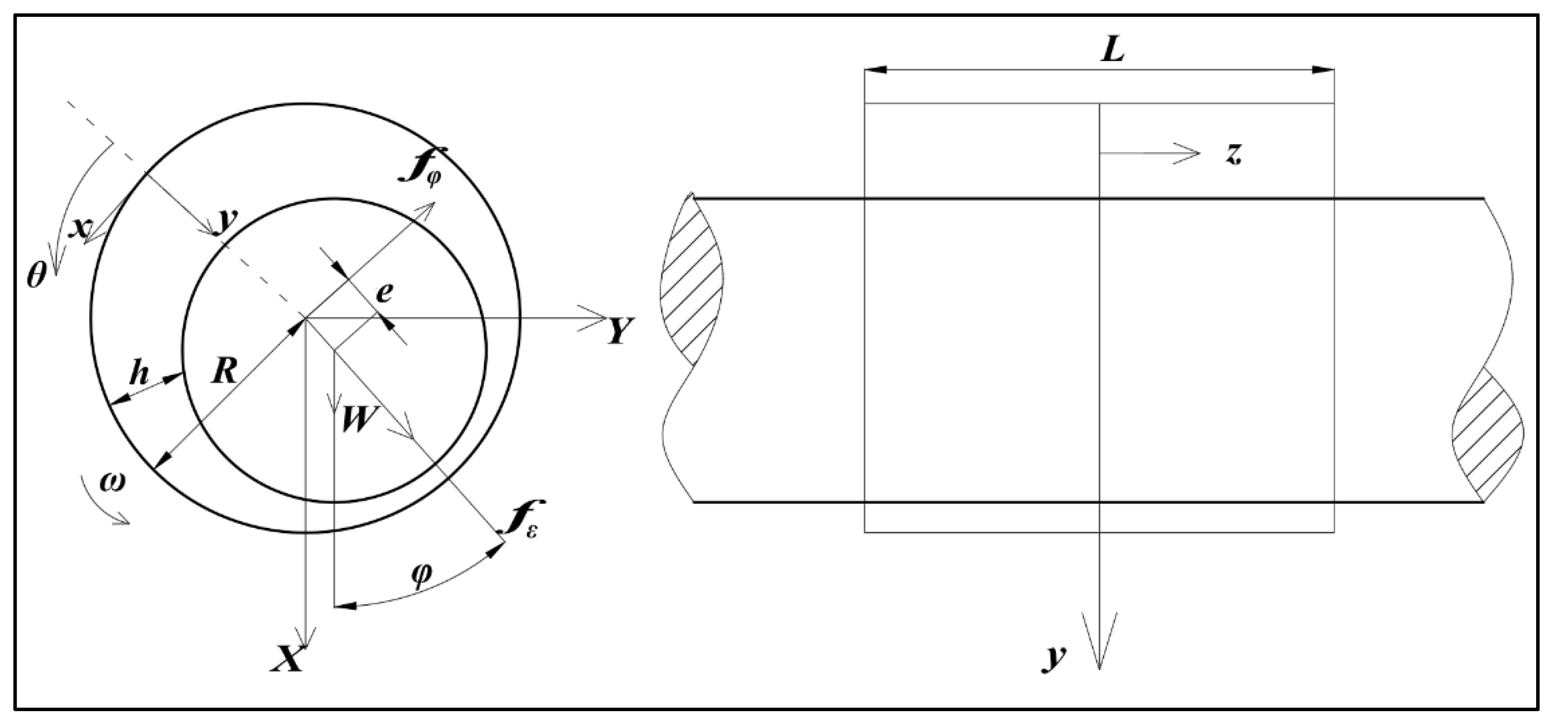
2. Theoretical Analysis

The schematic of the hydrodynamic journal bearing discussed in this study is depicted in Figure 1. The journal, with a radius denoted as R, rotates in an anticlockwise direction at an angular speed of ω. Following the approximation for journal bearings, the film thickness of bearings can be expressed as h = C + ecosθ, where C represents the radial clearance, e is the eccentricity, and θ is the angular coordinate of an arbitrary point on the bearing surface. Additionally, φ signifies the attitude angle, while fε represents the fluid force component in the eccentric direction, and fφ is the component perpendicular to it. The external load acting on the journal is denoted by W.
To avoid calculation errors, dimensionless quantities are applied in the derivation process. The substitution relationships are as follows:
x = R θ , z = L 2 z , α = k μ R ω C 2 , h = C h = C 1 + ε cos θ , e = C ε , p = μ ω R C 2 p , ε ˙ = 1 ω d ε d t , φ ˙ = 1 ω d φ d t
The dot ‘.’ above the variable means the first derivative of the variable with respect to time t. Considering the hydrodynamic bearing lubricated with non-Newtonian fluids, applying the short bearing model, the modified Reynolds equation can be written as follows [28]:
D L 2 z h 3 12 p z + α D L 2 h 5 80 p z 3 = 1 2 h θ + ε ˙ cos θ + ε φ ˙ sin θ
Here, D is the diameter of the bearing, and D = 2R.
To solve this non-linear differential equation, the small perturbation method is applied. Considering the small values of non-Newtonian factor α, the non-dimensional pressure p* could be written into [28]
p = p 0 + α p 1
Substituting Equation (4) into Equation (3), ignoring the high-order terms of α, using the pressure boundary conditions p 0 | z = ± 1 = 0 , p 1 | z = ± 1 = 0 , the non-dimensional pressure p* could be obtained as follows:
p = 3 L D 2 2 φ ˙ 1 ε sin θ + 2 ε ˙ cos θ 1 + ε cos θ 3 z 2 1 81 10 α L D 4 2 φ ˙ 1 ε sin θ + 2 ε ˙ cos θ 3 1 + ε cos θ 7 z 4 1
and the film forces are as follows:
f ε = μ ω L R 3 2 C 2 1 1 0 π p cos θ d θ d z
f φ = μ ω L R 3 2 C 2 1 1 0 π p sin θ d θ d z
The non-dimensional substitutions are as follows:
f ε = S W f ε , f φ = S W f φ , S = μ ω R L 3 2 W C 2 , ω = W m c ω
where S is the Sommerfeld number, and the expression of S is as follows:
S = 1 f ε 2 + f φ 2
The expressions of non-dimensional film forces are obtained:
f ε = 2 ε 2 ( 2 φ ˙ 1 ) 1 ε 2 2 π ε ˙ 1 + 2 ε 2 1 ε 2 5 2 + 81 25 α L D 2 ( 2 φ ˙ 1 ) 3 ε 3 1 ε 2 5 8 5 ε + 4 15 ε 3 + 6 ( 2 φ ˙ 1 ) 2 ε 2 ε ˙ 1 ε 2 11 2 1 8 + 17 16 ε 2 + 1 8 ε 4 π 12 ( 2 φ ˙ 1 ) ε ε ˙ 2 1 ε 2 6 14 5 ε + 36 5 ε 3 + 2 3 ε 5 + 8 ε ˙ 3 1 ε 2 13 2 3 8 + 101 16 ε 2 29 4 ε 4 + 1 2 ε 6 π
f φ = π ( 1 2 φ ˙ ) ε 2 1 ε 2 3 2 + 4 ε ˙ ε 1 ε 2 2 + 81 25 α L D 2 ( 2 φ ˙ 1 ) 3 ε 3 1 ε 2 9 2 3 8 + 1 16 ε 2 π 6 ( 2 φ ˙ 1 ) 2 ε 2 ε ˙ 1 ε 2 5 28 15 ε + 4 15 ε 3 + 12 ( 2 φ ˙ 1 ) ε ε ˙ 2 1 ε 2 6 1 8 + 17 16 ε 2 + 1 8 ε 4 π 8 ε ˙ 3 1 ε 2 6 14 5 ε + 36 5 ε 3 + 2 3 ε 5
The analytical integration of Equations (6) and (7) is not obvious at all. The procedure is quite complex, cumbersome, and the reader will appreciate the detailed presentation in Appendix A.
Setting the first and second derivatives of ε and φ to zero, the attitude angle of equilibration point φs is obtained as follows:
φ s = tan 1 ( f φ f ε ) = tan 1 π ε s 1 ε s 2 7 2 162 25 α π L D 2 ε s 3 1 ε s 2 1 2 3 8 + 1 16 ε s 2 4 ε s 2 1 ε s 2 3 + 162 25 α L D 2 ε s 3 8 5 ε s + 4 15 ε s 3
Ignoring the deformation and tilt of the journal, applying the Newton second law along the line of centers and the direction perpendicular to it, the non-dimensional motion equations of the journal can be expressed as follows [7]:
ω 2 ε ¨ ε φ ˙ 2 S f ε cos φ = 0
ω 2 ε φ ¨ + 2 ε ˙ φ ˙ S f φ + sin φ = 0
And the acceleration of the journal center in the eccentric and circumferential directions is as follows:
ε ¨ = S f ε + cos φ ω 2 + ε φ ˙ 2
φ ¨ = 1 ε S f φ sin φ ω 2 2 ε ˙ φ ˙
Let us consider a situation where the journal suddenly leaves the equilibration location by being impacted on a transient force and reaches a location of (ε0, φ0). As the impact force is transient, the velocity components of the journal center at this point could be regarded as 0. Thus, the initial conditions of acceleration equations could be written as follows:
ε ( 0 ) = ε 0 φ ( 0 ) = φ 0 ε ˙ ( 0 ) = 0 φ ˙ ( 0 ) = 0   at   t = 0
With Equations (10), (11) and (15)–(17), applying the fourth-order Runge–Kutta method, the journal center trajectory depending upon time could be obtained.
Applying the Routh–Hurwitz stability criterion, the threshold speed of the hydrodynamic journal bearing is found [7] as follows:
ω s = d 1 d 3 d 4 d 4 2 d 1 d 2 d 4 + d 1 2 d 5
where
d 1 = A X X + A Y Y d 2 = K X X + K Y Y d 3 = A X X A Y Y A X Y A Y X d 4 = K X X A Y Y + K Y Y A X X K X Y A Y X K Y X A X Y d 5 = K X X K Y Y K X Y K Y X
Here, the parameters K ij and A ij (i, j = X, Y) are the stiffness and damping coefficients of the bearing. And the values of K ij and A ij could be obtained by applying the following transformational relations [11]:
K X X K Y X K X Y K Y Y s = S cos φ sin φ sin φ cos φ s f ε ε f φ ε f ε ε φ f φ ε f φ ε φ + f ε ε s cos φ sin φ sin φ cos φ T s
A X X A Y X A X Y A Y Y s = S cos φ sin φ sin φ cos φ s f ε ε ˙ f φ ε ˙ f ε ε φ ˙ f φ ε φ ˙ s cos φ sin φ sin φ cos φ T s
The subscript s denotes the situation of the journal at the equilibrium location. And the expressions of partial derivatives in Equations (20) and (21) are expressed as follows:
f ε ε = 4 ε 1 + ε 2 3 1 ε 2 3 + 216 125 α L D 2 ε 3 12 + 21 ε 2 + 2 ε 4 1 ε 2 6
f ε ε φ f φ ε = π 2 1 ε 2 3 2 + 81 400 α L D 2 ε 2 6 + ε 2 1 ε 2 9 2
f φ ε = π 1 + 2 ε 2 2 1 ε 2 5 2 81 400 α L D 2 ε 2 18 + 41 ε 2 + 4 ε 4 1 ε 2 11 2
f φ ε φ + f ε ε = 2 ε 1 ε 2 2 + 108 125 α L D 2 ε 3 6 + ε 2 1 ε 2 5
f ε ε ˙ = π 1 + 2 ε 2 1 ε 2 5 2 + 243 200 α L D 2 ε 2 2 + 17 ε 2 + 2 ε 4 π 1 ε 2 11 2
f ε ε φ ˙ = 4 ε 1 ε 2 2 648 125 α L D 2 ε 3 6 + ε 2 1 ε 2 5
f φ ε ˙ = 4 ε 1 ε 2 2 + 648 125 α L D 2 ε 3 7 + ε 2 1 ε 2 5
f φ ε φ ˙ = π 1 ε 2 3 2 + 243 200 α L D 2 ε 2 6 + ε 2 1 ε 2 9 2
After identifying the linear stability threshold speed, a rotating speed could be selected below this threshold speed. By incorporating this chosen speed into the state Equation (18) and employing the fourth-order Runge–Kutta method, the trajectory of the journal center for the specified rotating speed can be determined. For each designated rotating speed, a distinctive non-linear stability boundary could be established. If the rotating speed of the journal is under the threshold speed and the journal center is in the stability region, the journal would gradually go back to the equilibrium location after an instantaneous impulsion is impacted on the journal. The program flow chart depicted in Figure 2 is utilized to ascertain and visualize the stability boundary. The specific steps to confirm the non-linear stability boundary of a hydrodynamic bearing are as follows:
(1)
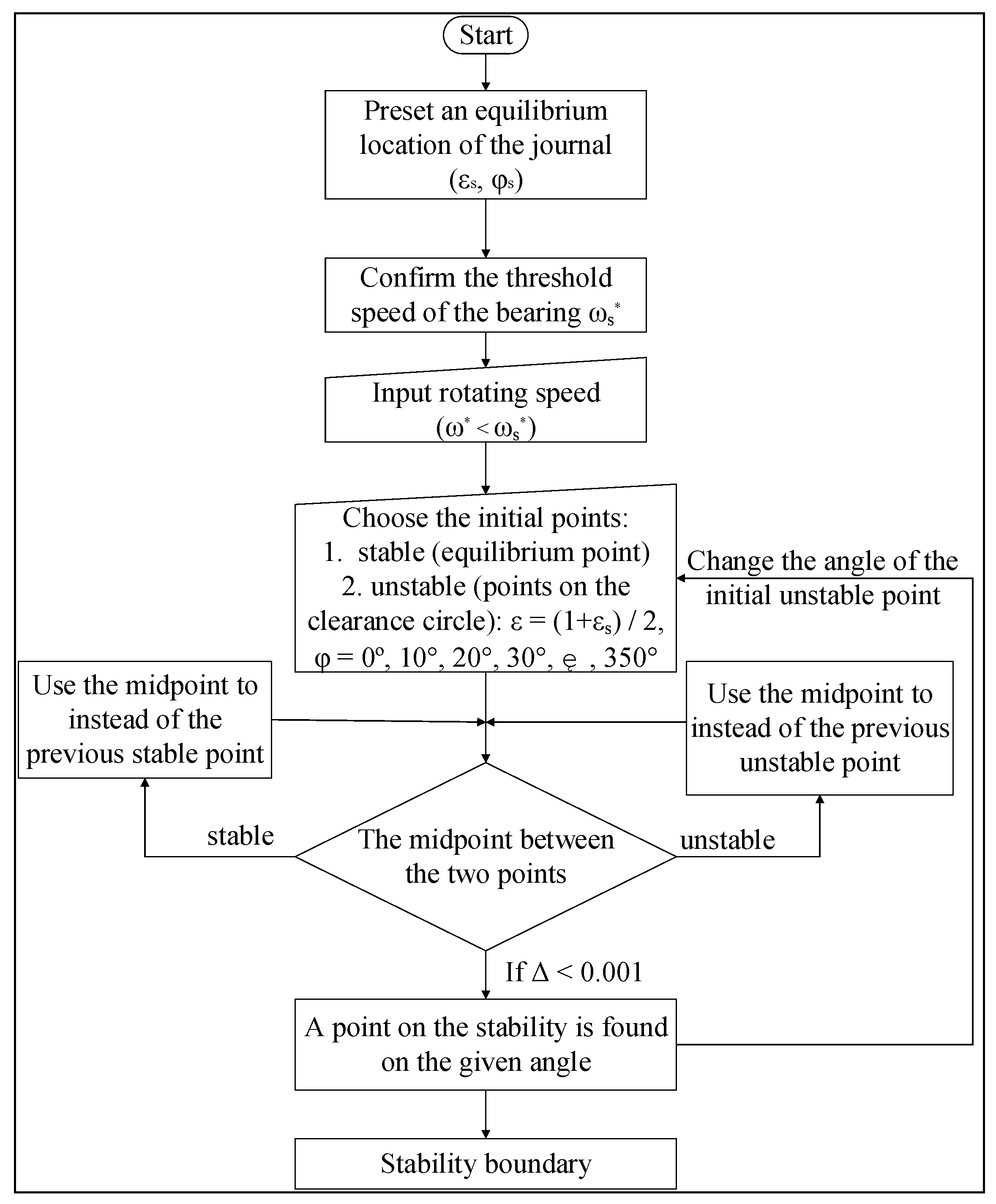
From Equation (11), an equilibrium location of the journal center could be preset.
(2)
For the given location of the journal center, substituting the position coordinates into Equation (24), the threshold speed of the hydrodynamic bearing at the given equilibrium location could be obtained.
(3)
Choosing a rotating speed less than the threshold speed and an initial location of the journal center, to confirm the stability boundary more conveniently, the initial location of the journal center is chosen as follows:
(a)
Set the line connecting the bearing center and equilibrium location of the journal center as the starting line, dividing the clearance circle into n parts (generally, the value of n is 36. To make the results more accurate, the value of n could be larger. To shorten the calculation process, the value of n could be smaller. We confirm that the value of n should be larger than 9). Here, n = 36, and 36 points on the clearance circle is found. The eccentricity ratios of all the points are 1, and the attitude angles of these points are 0°, 10°, 20° … 350°.
(b)
First, choose the location ε = (1 + εs)/2, φ = 0° as the initial point of the journal center. With Equations (9), (10) and (14)–(16), applying the fourth-order Runge–Kutta method, the trajectory of the journal center could be obtained.
(c)
If the journal center gradually gets close to the bearing surface, choose the middle point between this point and the equilibrium location as the next point.
(d)
If the journal center gradually gets close to the equilibrium location, choose the middle point between this point and the last initial location as the next point.
(e)
With the location of new point, repeat the steps (b) to (d), until the difference between eccentricity ratios of two continuity points is less than 0.001. Then, choose one of these two points, and this point is the point on the stability boundary with the attitude angle of 0°.
(f)
Choosing the location ε = 1, φ = 10° as the initial point of the journal center and repeating the steps (b) to (e), the point on the stability boundary with the attitude angles of 10° is found. Continuing to repeat the steps (b) to (e), the points on the stability boundary with the attitude angles of 20°, 30°, …, and 350° are found.
(4)
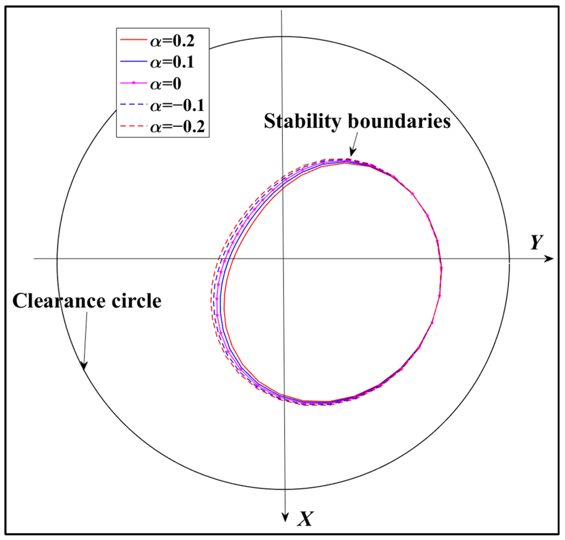
After the 36 points on the stability boundary are confirmed, connect these points with a smooth curve, and the stability boundary of the hydrodynamic bearing with the given equilibrium location is obtained.

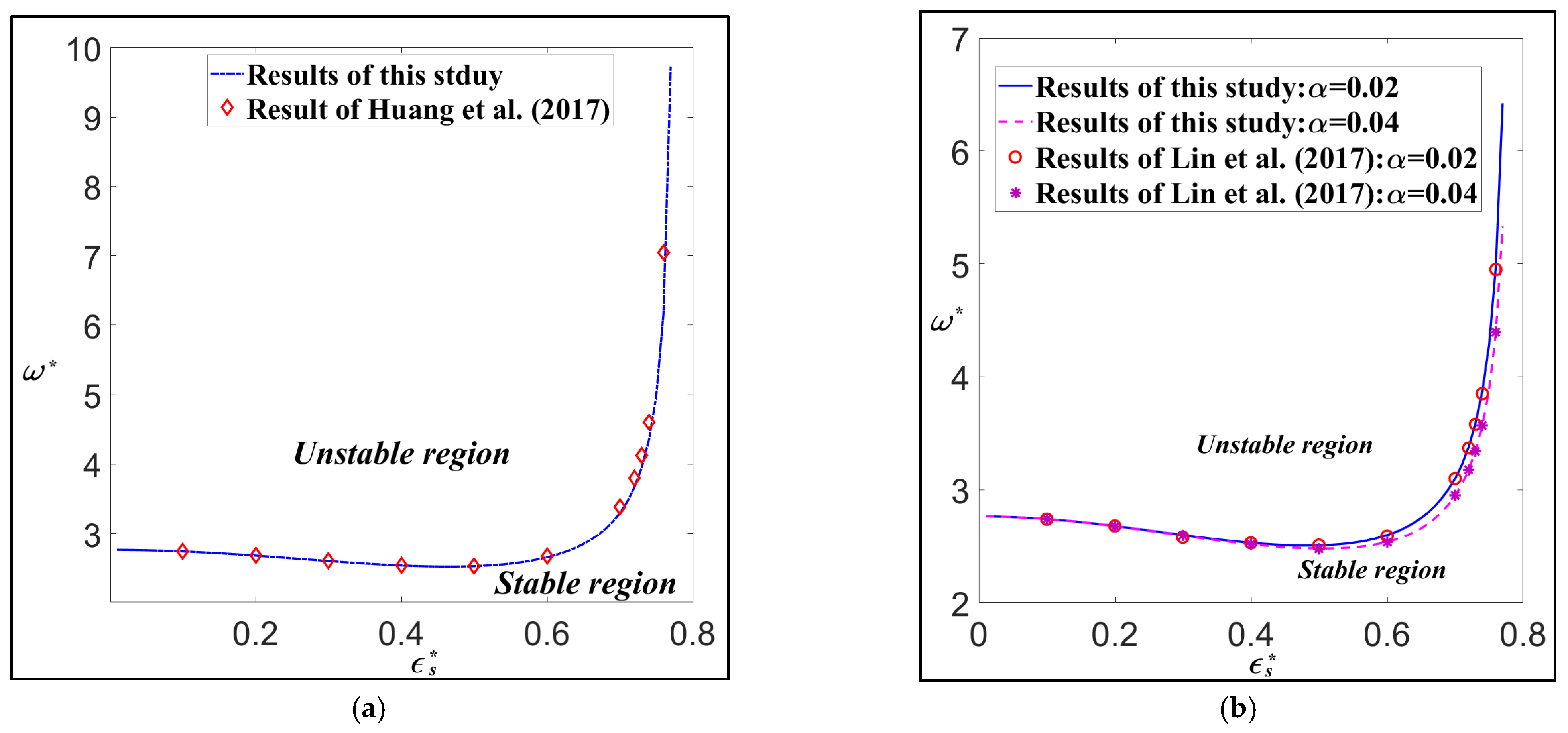
3. Verification of the Results

The modified Reynolds equation of hydrodynamic bearings lubricated with non-Newtonian fluids is established by applying the Rabinowitsch fluid model. The non-linear equation is solved through the small perturbation method, and oil film forces are obtained in the form of analytical expression. Then, the stiffness and damping coefficients and threshold speed of the bearing are derived. By tracing the trajectory of the journal center diverging from the equilibrium location, the non-linear stability boundary can be confirmed. To verify the accuracy of the calculation process above, the relationship between the threshold speed and the eccentricity ratio of the journal center at the equilibrium state is compared with that of refs. [10,28]. The comparison is presented in Figure 3: in Figure 3a, the lubricant is Newtonian lubricant, and the results of this study are compared with those of ref. [10], while in Figure 3b, the comparison between this study and ref. [28] is presented. It can be found that the results in this study agree well with those of refs. [10,28] for all the three situations: the Newtonian lubricant, the non-Newtonian factor α = 0.02 and 0.04. Thus, the theoretical calculation in this study is credible.

4. Results and Discussions

The effects of non-Newtonian fluids on the threshold speed and non-linear stability boundary of hydrodynamic bearings are illustrated in this study, and the ratio between the length and diameter of the bearing is L/D = 0.25. The non-Newtonian factors of several typical dilatant fluids have been displayed in Table 1, applying the Rabinowitsch fluid model, three kinds of lubricants are discussed: dilatant fluids with non-Newtonian factor α < 0, Newtonian fluids with non-Newtonian factor α = 0, and pseudo-plastic fluids with non-Newtonian factor α > 0. Except for the Newtonian lubricant, for both the non-Newtonian lubricants, two situations are discussed: α = −0.1, −0.2 and α = 0.1, 0.2. The influence of non-Newtonian lubricants on the threshold speed of hydrodynamic bearings is presented in Figure 4. The trajectories of the journal center released at different locations are shown in Figure 5. The non-linear stability boundaries of hydrodynamic bearings with five lubricants are demonstrated in Figure 6.
The relationships between threshold speeds and eccentricity ratios of hydrodynamic bearings are displayed in Figure 4. And five kinds of lubricants are applied to the bearing: two dilatant fluids with non-Newtonian factor α = −0.1, −0.2, one Newtonian fluid with α = 0, and two pseudo-plastic fluids with α = 0.1, 0.2. With the increase in the eccentricity ratio, the threshold speed of hydrodynamic bearings with dilatant lubricants and Newtonian lubricants would first decrease slowly and then increase quickly. For the bearing with the pseudo-plastic lubricant, the threshold speed would decrease all the time: when the eccentricity ratio is less than 0.55, the rate of descent is slow; for the situation of the eccentricity ratio lager than 0.55, the rate of decent is sharp. It was found that the influence of the lubricants on the threshold speed can be ignored when the eccentricity ratio of journal center is less than 0.4. For the situation of an eccentricity ratio larger than 0.6, with the increase in eccentricity ratio, the threshold speeds of bearings lubricated with Newtonian fluids and dilatant fluids would increase, while that of the bearing with pseudo-plastic lubricants would reduce. The influence of lubricants would be more obvious when the absolute value of the non-Newtonian factor is greater. And for dilatant lubricants, the absolute value of non-Newtonian factor is greater, and the threshold speed of hydrodynamic bearings is higher, while for the pseudo-plastic lubricants, the smaller absolute value of the non-Newtonian factor means a higher threshold speed.
To illustrate the performance of non-linear stability boundary of the hydrodynamic bearing, three initial locations are chosen for the journal center in Figure 5: the initial location C1 is in the stability region, C2 is on the stability boundary, and C3 is out of the stability region. The operational states of the bearing are ε s = 0.3, φ s = 1.1899 rad, ω* = 2. The threshold speed ω s = 2.6058, and the lubricant is Newtonian fluid. As the rotating speed of the journal is less than the threshold speed, when the journal center is released in the clearance circle, there are three kinds of situations: (1) The initial location of journal center is in the stability region, as shown by the point C1 in Figure 5. In this situation, the journal center would gradually come back to the equilibrium location as shown in Figure 5. If the initial location of the journal center is on the stability boundary like the point C2, the journal center would be in dynamic equilibrium, and the trajectory of the journal center would be a cycle which contains the equilibrium location. (3) For the initial location of the journal center outside the boundary, as shown by the point C1 in Figure 5, after being released, the journal center would gradually get close to the bearing surface until it reaches and destroys the bearing.
In Figure 6, the non-linear stability boundaries of hydrodynamic journal bearings lubricated with different kinds of fluids are presented. There are three kinds of lubricants: dilatant fluids with non-Newtonian factor α = −0.1 and −0.2, Newtonian fluid with α = 0, and pseudo-plastic fluids with α = 0.1 and 0.2. It is observed that the stability region of bearings lubricated with dilatant fluids is larger than that of bearings with Newtonian fluids, and the stability region of bearings lubricated with pseudo-plastic fluids is smaller than that of bearings with Newtonian fluids. And for a lubricant with a larger non-Newtonian factor, the stability boundary of the bearing lubricated by this fluid would be smaller. Generally speaking, for a hydrodynamic bearing with a larger non-linear stability region, the stability of the bearing would be better. Thus, the stability of hydrodynamic bearings lubricated with dilatant fluids is better than those lubricated with Newtonian fluids, while the stability of bearings lubricated with pseudo-plastic fluids is inferior to those lubricated with Newtonian fluids. For the dilatant lubricant, the larger absolute value of the non-Newtonian factor means a better stability of the bearing, while for the pseudo-plastic lubricant, the smaller absolute value of the non-Newtonian factor shows a better stability of the bearing.

5. Conclusions

Applying the Rabinowitsch fluid model, this study presents the non-linear stability boundaries of short hydrodynamic bearings lubricated with three kinds of fluids. Two non-linear differential motion equations are effectively solved by using the fourth-order Runge–Kutta method, allowing for the tracing of the journal center’s trajectory. Based on the discussion above, the following conclusions could be obtained:
(1)
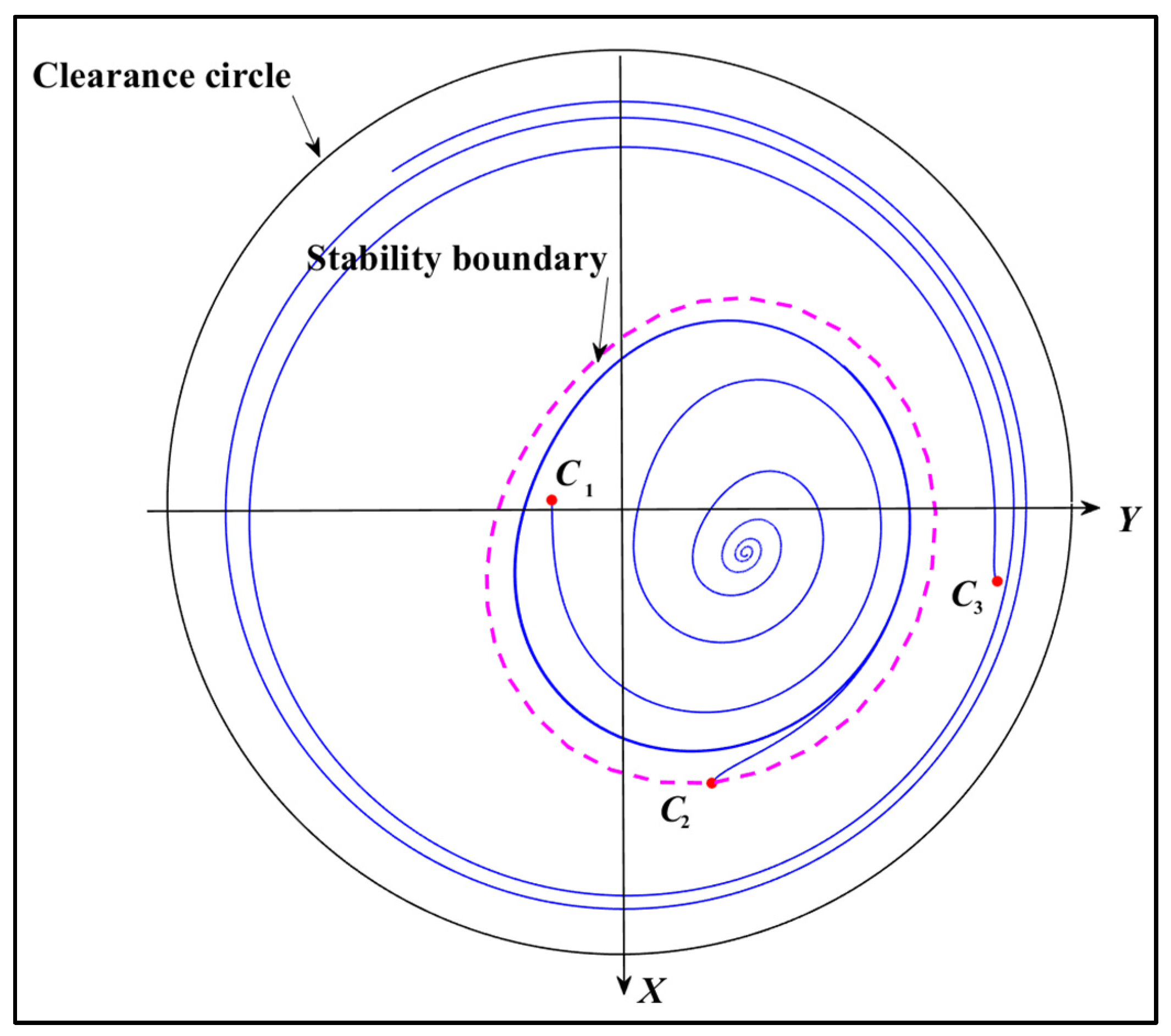
A non-linear stability boundary exists for short journal bearings within the clearance circle. The trajectory of the journal center, starting outside this boundary, becomes unstable, and even the rotating speed is below the threshold speed. The threshold speed of hydrodynamic bearings with pseudo-plastic lubricants (α > 0) is higher than that of bearings with Newtonian lubricants (α = 0). And the threshold speed of bearings with Newtonian lubricants is higher than that of bearings with pseudo-plastic lubricants (α > 0).
(2)
The non-linear stability region of bearings lubricated with pseudo-plastic lubricants (α > 0) is smaller than that of bearings lubricated with Newtonian lubricants (α = 0). The non-linear stability region of bearings with dilatant lubricants (α < 0) is larger than that of bearings lubricated with Newtonian lubricants (α = 0). The bearing using lubricants with a higher non-Newtonian factor exhibits a smaller non-linear stability boundary.
(3)
Generally, a larger stability region and a higher threshold speed indicate the better stability of the hydrodynamic bearing, and the non-linear stability of bearings is affected by the lubricant. For the three kinds of lubricants discussed in this study, in the hydrodynamic bearing with a lubricant with the smaller value of the non-Newtonian factor, the stability of the bearing is better. Thus, it is confirmed that the choice of a more appropriate lubricant can enhance the stability of bearings. The results in this study provide engineers with greater flexibility in the practical design of hydrodynamic bearings.

Author Contributions

Methodology, Z.T.; formal analysis, Z.T.; investigation, H.L.; writing—original draft preparation, C.C.; writing—review and editing, H.L. All authors have read and agreed to the published version of the manuscript.

Funding

This research is supported by National Key Research and Development Program of China (No. 2020YFB2007600).

Data Availability Statement

The original contributions presented in this study are included in the article. Further inquiries can be directed to the corresponding author.

Conflicts of Interest

The authors declare no conflicts of interest. The funders had no role in the design of the study; in the collection, analyses, or interpretation of data; in the writing of the manuscript; or in the decision to publish the results.

Abbreviations

Nomenclatureωrotation speed of shaft: rad/s
θangular coordinate, rad
Cradial clearance, mmεeccentricity ratio, e/c
Djournal diameter, mmNon-dimensional parameters
ejournal eccentricity, mm
fεfluid film reaction component on the eccentric direction, N K i j ,   C i j non-dimensional stiffness and damping coefficients, i, j = X, Y
fφfluid film reaction component perpendicular to the eccentric direction, Nh* =h/c
FXfluid film reaction component on X direction, Nα =k(μRω/C)2
FYfluid film reaction component on Y direction, Np* =pC2/μωR2
hfilm thickness, mmω* =ω(W/mC)1/2
Lbearing length, mm ω s =non-dimensional stability threshold speed
knon-Newtonian factor, mm4·N−2 ω 2 =non-dimensional second threshold speed
mmass of rotor per each bearing, kgS =μωRL3/(2WC2)
ppressure, N·mm−2z* =2z/L
Rradius of journal, mmfε* =Fε/(SW)
ttime, sfφ* =Fφ/(SW)
Wexternal load, NFX* =FX/(SW)
X, Y, ZCartesian coordinatesFY* =FY/(SW)
xcoordinate of circumferential direction, mmSubscripts and superscripts
ycoordinate of the eccentric direction, mm
zcoordinate of axial direction, mmsstability state
Greek symbolsεcomponent on eccentric direction
φcomponent perpendicular to eccentric direction
φattitude angle, rad*non-dimensional parameter
μviscosity of zero shear rate, N·s·m−2.first derivative with respect to time
γshear strain..second derivative with respect to time

Appendix A

With the non-dimensional substitutions in Equation (8), the components of oil film force can be written in non-dimensional forms as follows:
f ε = 1 1 0 π p cos θ d θ d z
f φ = 1 1 0 π p sin θ d θ d z
Substituting the expression of pressure distribution (5) and integrating Equations (A1) and (A2) with respect to z from −1 to 1, the components of oil film force are changed into the following:
f ε = 0 π 4 L D 2 2 φ ˙ 1 ε sin θ + 2 ε ˙ cos θ 1 + ε cos θ 3 81 25 α L D 4 2 φ ˙ 1 ε sin θ + 2 ε ˙ cos θ 3 1 + ε cos θ 7 cos θ d θ
f φ = 0 π 4 L D 2 2 φ ˙ 1 ε sin θ + 2 ε ˙ cos θ 1 + ε cos θ 3 81 25 α L D 4 2 φ ˙ 1 ε sin θ + 2 ε ˙ cos θ 3 1 + ε cos θ 7 sin θ d θ
The Sommerfeld substitution is applied as follows [35]:
h = 1 + ε cos θ = 1 ε 2 1 ε cos β
And the following relations could be obtained:
sin θ = 1 ε 2 sin β 1 ε cos β , cos θ = cos β ε 1 ε cos β , d θ = 1 ε 2 1 ε cos β d β
Substituting Equation (A6) into Equations (A3) and (A4), the following are obtained:
f ε = 0 π 4 L D 2 2 φ ˙ 1 ε 1 ε 2 sin β + 2 ε ˙ cos β ε 1 ε 2 5 2 81 25 α L D 4 1 ε cos β 2 2 φ ˙ 1 ε 1 ε 2 sin β + 2 ε ˙ cos β ε 3 1 ε 2 13 2 cos β ε d β
f φ = 0 π 4 L D 2 2 φ ˙ 1 ε 1 ε 2 sin β + 2 ε ˙ cos β ε 1 ε 2 2 81 25 α L D 4 1 ε cos β 2 2 φ ˙ 1 ε 1 ε 2 sin β + 2 ε ˙ cos β ε 3 1 ε 2 6 sin β d β
It was found that Equations (A7) and (A8) are a general integration of trigonometric functions, and the expressions of oil film forces in Equations (10) and (11) could be easily obtained from Equations (A7) and (A8).

References

  1. Hollis, P.; Taylor, D.L. Hopf Bifurcation to Limit Cycles in Fluid Film Bearings. J. Tribol. 1986, 108, 184–189. [Google Scholar] [CrossRef]
  2. Crooijmans, M.T.M.; Brouwers, H.J.H.; van Campen, D.H.; De Kraker, A. Limit Cycle Predictions of a Nonlinear Journal-Bearing System. J. Eng. Ind. 1990, 112, 168–171. [Google Scholar] [CrossRef]
  3. Wang, J.K.; Khonsari, M.M. Prediction of the stability envelope of rotor-bearing system. J. Vib. Acoust. 2006, 128, 197. [Google Scholar] [CrossRef]
  4. Lin, J.R. The surface roughness effects of transverse patterns on the Hopf bifurcation behaviors of short journal bearings. Ind. Lubr. Tribol. 2012, 64, 265–270. [Google Scholar] [CrossRef]
  5. Lin, J.R. Application of the Hopf bifurcation theory to limit cycle prediction of short journal bearings with isotropic roughness effects. Proc. Inst. Mech. Eng. Part J J. Eng. Tribol. 2007, 221, 869–879. [Google Scholar] [CrossRef]
  6. Lin, J.R. The influences of longitudinal surface roughness on sub-critical and super-critical limit cycles of short journal bearings. Appl. Math. Model. 2014, 38, 392–402. [Google Scholar] [CrossRef]
  7. Khonsari, M.M.; Chang, Y.J. Stability boundary of non-linear orbits within clearance circle of journal bearings. J. Vib. Acoust. 1993, 115, 303–307. [Google Scholar] [CrossRef]
  8. Wang, J.K.; Khonsari, M.M. A new derivation for journal bearing stiffness and damping coefficients in polar coordinates. J. Sound Vib. 2006, 290, 500–507. [Google Scholar] [CrossRef]
  9. Amamou, A.; Chouchane, M. Nonlinear stability analysis of long hydrodynamic journal bearings using numerical continuation. Mech. Mach. Theory 2014, 72, 17–24. [Google Scholar] [CrossRef]
  10. Huang, Y.; Tian, Z.; Chen, R.; Cao, H. A simpler method to calculate instability threshold speed of hydrodynamic journal bearings. Mech. Mach. Theory 2017, 108, 209–216. [Google Scholar] [CrossRef]
  11. Tian, Z.; Huang, Y. Transformation between polar and rectangular coordinates of stiffness and dampness parameters in hydrodynamic journal bearings. Friction 2021, 9, 201–206. [Google Scholar] [CrossRef]
  12. Dyk, Š.; Rendl, J.; Byrtus, M.; Smolík, L. Dynamic coefficients and stability analysis of finite-length journal bearings considering approximate analytical solutions of the Reynolds equation. Tribol. Int. 2019, 130, 229–244. [Google Scholar] [CrossRef]
  13. El-Sayed, T.A.; Sayed, H. Bifurcation analysis of rotor/bearing system using third-order journal bearing stiffness and damping coefficients. Nonlinear Dyn. 2022, 107, 123–151. [Google Scholar] [CrossRef]
  14. Lin, C.; Jian, F.; Sun, S.; Sima, C.; Qi, L.; Zou, M. Analysis of nonlinear time-domain lubrication characteristics of the hydrodynamic journal bearing system. Lubricants 2023, 11, 145. [Google Scholar] [CrossRef]
  15. Huang, Y.; Cao, H.; Tian, Z. Stability analysis of long hydrodynamic journal bearings based on the journal center trajectory. Friction 2021, 9, 1776–1783. [Google Scholar] [CrossRef]
  16. Mao, Y.; Li, L.; Li, D.; Zheng, J. Analysis of the turbulent lubrication of a textured hydrodynamic journal bearing. Lubricants 2023, 11, 362. [Google Scholar] [CrossRef]
  17. Dakel, M.; Baguet, S.; Dufour, R. Nonlinear dynamics of a support-excited flexible rotor with hydrodynamic journal bearings. J. Sound Vib. 2014, 333, 2774–2799. [Google Scholar] [CrossRef]
  18. Miraskari, M.; Hemmati, F.; Gadala, M.S. Nonlinear dynamics of flexible rotors supported on journal bearings—Part I: Analytical bearing model. J. Tribol. 2018, 140, 021704. [Google Scholar] [CrossRef]
  19. Miraskari, M.; Hemmati, F.; Gadala, M.S. Nonlinear dynamics of flexible rotors supported on journal bearings—Part II: Numerical bearing model. J. Tribol. 2018, 140, 021705. [Google Scholar] [CrossRef]
  20. Machado, T.H.; Alves, D.S.; Cavalca, K.L. Discussion about nonlinear boundaries for hydrodynamic forces in journal bearing. Nonlinear Dyn. 2018, 92, 2005–2022. [Google Scholar] [CrossRef]
  21. Swamy, S.T.N.; Prabhu, B.S.; Rao, B.V.A. Stiffness and damping characteristics of finite width journal bearings with a non-Newtonian film and their application to instability prediction. Wear 1975, 32, 379–390. [Google Scholar] [CrossRef]
  22. Swamy, S.T.N. The influence of non-Newtonian oil film short journal bearings on the stability of a rigid rotor. Wear 1977, 43, 155–164. [Google Scholar] [CrossRef]
  23. Lin, J.R.; Li, P.J.; Hung, T.C.; Liang, L.J. Nonlinear stability boundary of journal bearing systems operating with non-Newtonian couple stress fluids. Tribol. Int. 2014, 71, 114–119. [Google Scholar] [CrossRef]
  24. Lu, H.; Tian, Z. Investigation of the static performance of hydrostatic thrust bearings considering non-Gaussian surface topography. Lubricants 2023, 11, 267. [Google Scholar] [CrossRef]
  25. Walicka, A.; Walicki, E.; Jurczak, P.; Falicki, J. Thrust bearing with rough surfaces lubricated by an Ellis fluid. Int. J. Appl. Mech. Eng. 2014, 19, 809–822. [Google Scholar] [CrossRef]
  26. Wada, S.; Hayashi, H. Hydrodynamic lubrication of journal bearings by pseudo-plastic lubricants: Part 1, theoretical studies. Bull. JSME 1971, 14, 268–278. [Google Scholar] [CrossRef]
  27. Wada, S.; Hayashi, H. Hydrodynamic lubrication of journal bearings by pseudo-plastic lubricants: Part 2, experimental studies. Bull. JSME 1971, 14, 279–286. [Google Scholar] [CrossRef]
  28. Lin, J.R.; Hung, T.C.; Lin, C.H. Linear stability analysis of journal bearings lubricated with a non-Newtonian Rabinowitsch fluid. J. Mech. 2017, 35, 107–112. [Google Scholar] [CrossRef]
  29. Tian, Z.; Chen, R. A derivation of stiffness and damping coefficients for short hydrodynamic journal bearings with pseudo-plastic lubricants. J. Mech. 2020, 36, 943–953. [Google Scholar] [CrossRef]
  30. Sharma, S.C.; Yadav, S.K. Performance of hydrostatic circular thrust pad bearing operating with Rabinowitsch fluid model. Proc. Inst. Mech. Eng. Part J J. Eng. Tribol. 2013, 227, 1272–1284. [Google Scholar] [CrossRef]
  31. Singh, U.P.; Gupta, R.S.; Kapur, V.K. On the steady performance of hydrostatic thrust bearing: Rabinowitsch fluid model. Tribol. Trans. 2011, 54, 723–729. [Google Scholar] [CrossRef]
  32. Singh, U.P.; Gupta, R.S.; Kapur, V.K. On the application of Rabinowitsch fluid model on an annular ring hydrostatic thrust bearing. Tribol. Int. 2013, 58, 65–70. [Google Scholar] [CrossRef]
  33. Lin, J.R. Non-Newtonian effects on the dynamic characteristics of one-dimensional slider bearings: Rabinowitsch fluid model. Tribol. Lett. 2001, 10, 237–243. [Google Scholar] [CrossRef]
  34. Lin, J.R.; Chu, L.M.; Hung, T.C.; Wang, P.Y. Derivation of two-dimensional non-Newtonian Reynolds equation and application to power-law film slider bearings: Rabinowitsch fluid model. Appl. Math. Model. 2016, 40, 8832–8841. [Google Scholar] [CrossRef]
  35. Sommerfeld, A. Zürhydrodynamischen theorie der schmiermittelreibung. Z. Math. Phys. 1904, 50, 155. [Google Scholar]
Figure 1. Schematic of the hydrodynamic journal bearing.
Lubricants 13 00194 g001
Figure 2. The program flow chart to calculate the stability boundary.
Lubricants 13 00194 g002
Figure 3. Result comparisons between this study and previous studies. (a) Newtonian lubricants [10]. (b) Non-Newtonian lubricants [28].
Lubricants 13 00194 g003
Figure 4. The threshold speed of hydrodynamic journal bearings lubricated with different fluids: dilatant fluids with non-Newtonian factor α < 0, Newtonian fluids with non-Newtonian factor α = 0, and pseudo-plastic fluids with the non-Newtonian factor α > 0.
Lubricants 13 00194 g004
Figure 5. The non-linear stability boundary and trajectories of journal center released at different initial locations.
Lubricants 13 00194 g005
Figure 6. The non-linear stability boundaries of hydrodynamic bearings lubricated with different kinds of lubricants.
Lubricants 13 00194 g006
Table 1. The typical values for the non-Newtonian factors k [27].
Additives (%)T (°C)k (10−6 m4/N2)
0.3308.06
1.0304.43
2.0304.05
Disclaimer/Publisher’s Note: The statements, opinions and data contained in all publications are solely those of the individual author(s) and contributor(s) and not of MDPI and/or the editor(s). MDPI and/or the editor(s) disclaim responsibility for any injury to people or property resulting from any ideas, methods, instructions or products referred to in the content.

