Article

Leakage Flow Characteristics of Novel Two-Stage Brush Seal with Pressure-Equalizing Hole

Liaoning Key Lab of Advanced Test Technology for Aerospace Propulsion System, Shenyang Aerospace University, Shenyang 110136, China
*
Author to whom correspondence should be addressed.
Lubricants 2025, 13(4), 190; https://doi.org/10.3390/lubricants13040190
Submission received: 17 March 2025 / Revised: 16 April 2025 / Accepted: 18 April 2025 / Published: 19 April 2025

Abstract

:
Uneven inter-stage pressure drops of the common two-stage brush seal (CBS) lead to a problem that the second stage bristles bear excessive pressure load, and this problem leads to the premature failure of the brush seal. In this paper, a novel two-stage brush seal (NBS) with the backing plate holes of the second stage was proposed, and a three-dimensional numerical model of the NBS was established. Then, the effects of the pressure-equalizing (PE) hole on the inter-stage pressure drop distribution of the NBS were numerically analyzed, and an optimal structure was obtained. Finally, the leakage flow characteristics of this optimal structure were studied. The results showed that the NBS with PE hole increased the passage area of the downstream, and so effectively improved the uneven pressure drops of the CBS, and the pressure drop balance ratio of the NBS was obviously smaller than that of the CBS. For the structural parameters studied in this paper, the pressure drop balance ratio of the NBS was improved by 45.6~67.9% compared to the CBS. Moreover, when PE holes were 0.4 mm in diameter, 5.95 mm in height, and the number of rows was 1, the NBS had the best pressure drop balance and its leakage was only 8.7% higher than that of the CBS.

1. Introduction

A brush seal is an advanced contacting dynamic seal, and its leakage is 10~20% of the traditional labyrinth seal [1,2,3,4]. The brush seal has a simple structure, low manufacturing cost and excellent sealing performance, so brush seals have important applications in turbine machinery such as aero-engines. With the continuous improvement of aero-engine performance parameters, the pressure-bearing capacity of the single-stage brush seal is limited, so the multi-stage brush seal is usually used in large-pressure-difference conditions [5,6,7].
Many researchers have proposed a variety of brush seal structures for different problems such as bristle disturbance and high downstream temperature, as shown in Figure 1. The series combination of traditional and low hysteresis single-stage brush seal was a commonly used multi-stage brush seal structure [8], as shown in Figure 1a,b. In order to further improve the sealing performance of the multi-stage brush seal, Addis et al. [9] proposed a multi-stage brush seal structure with an axial tilt, as shown in Figure 1c. The bristle pack of this structure tilted to the high-pressure side, and because of the action of air force, the bristle pack produced closure effect and axial deformation, which can reduce radial clearance to improve the sealing performance. Aiming at the problem that the front row bristles were susceptible to fatigue fracture caused by unstable air disturbance during operation, Tseng et al. [10] proposed a multi-stage brush seal structure with first-stage vibration-suppression elastic piece, as shown in Figure 1d. The vibration-suppression elastic piece could protect the front bristles and prolong the service life of the brush seal. Tanimura [11] proposed a multi-stage brush seal structure with inter-stage exhaust channel to solve the problem of high temperature of the final stage bristles, as shown in Figure 1e. This structure set an air leakage channel between the adjacent last two-stages, which was used to take away the high temperature air, reduce the temperature of the last stage bristle pack and prevent bristles from fusing due to the high temperature. Aiming at the problem of friction and wear of bristles caused by the radial runout of the rotor, Naert et al. [12]. proposed a multi-stage brush seal structure with radial arrangement of bristles, as shown in Figure 1f. This structure could alleviate the friction and wear of the bristles caused by the radial runout of the rotor. In addition, this structure was compact and light-weight.
However, the research showed that the above common multi-stage brush seal and its modification have a problem of uneven pressure distribution at all stages [13], which can lead to the premature failure of the last stage bristles. Therefore, it is of great significance to design a novel pressure-equalizing multi-stage brush seal based on the above structure and study its leakage flow characteristics.
Moreover, on the basis of structural research, many researchers have also conducted in-depth research on the leakage characteristics and pressure distribution characteristics of the multi-stage brush seal. Hendricks R C et al. [14] experimentally studied the pressure distribution of the two-stage brush seal, and concluded that the pressure drop of low-pressure side was about 20% greater than that of high-pressure side. Pugachev et al. [15] discovered the pressure drop imbalance phenomenon using the porous media method. Qiu et al. [16] studied the influence of rotational speed, pressure ratio and seal clearance on the leakage characteristics of the two-stage brush seal considering the decrease in clearance caused by centrifugal elongation of the rotor, and found that the pressure drop mainly occurred in the bristle pack area near the backing plate, and the pressure drop of downstream was larger than that of the upstream along the flow direction. Yang et al. [17] studied the influence of the structural parameters of the two-stage brush seal on the pressure distribution by using the three-dimensional solid fork tube bundle model. It was concluded that the inter-stage imbalance of the pressure drop could be aggravated under high-pressure conditions, and increasing the number of bristle axial rows of first stage could alleviate this inter-stage imbalance. Zhao et al. [18] studied the influence of structural parameters on pressure drop distribution, and proposed a multi-stage brush seal with a differentiated structure. Sun et al. [19] investigated the frictional heat flux, internal brush temperature distribution, leakage behavior and flow characteristics in the multi-stage brush seal, along with an analysis of the influencing factors of the frictional heat between the bristles and the rotor. The existing literature mostly studied the influencing factors of pressure distribution for the multi-stage brush seal, but literature on the new structure to balance the pressure drop among different stages is rarely published. However, in practical engineering applications, researchers have found that uneven inter-stage pressure drop will lead to premature failure of the final bristle pack under excessive pressure load, which will lead to the overall failure of the multi-stage brush seal and the short service life of the brush seal used in turbine machinery such as aero-engines. Therefore, it is of great significance to study a new structure of multi-stage brush seal with even pressure drop.
In this paper, an NBS with PE hole in the backing plate of the second stage was proposed according to the theory of pressure drop balance, and a numerical model of the NBS was established. On the basis of validation of the numerical model, the effects of structural parameters of PE holes on the inter-stage pressure drop distribution of the NBS were numerically analyzed, and an optimal structure was obtained. Then, the leakage flow characteristics of this optimal structure were studied.

2. NBS Structure Design

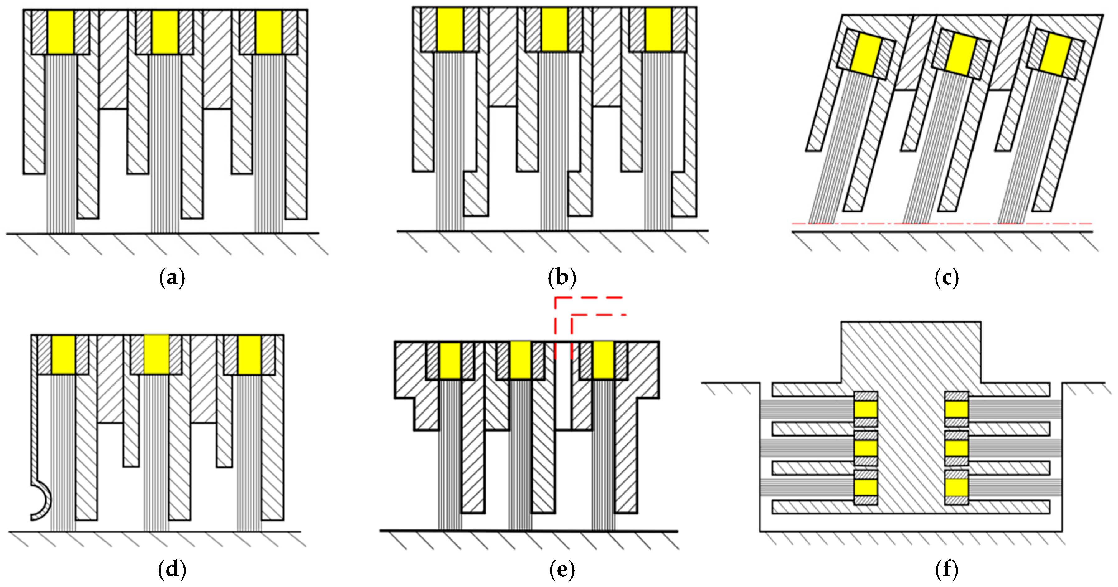
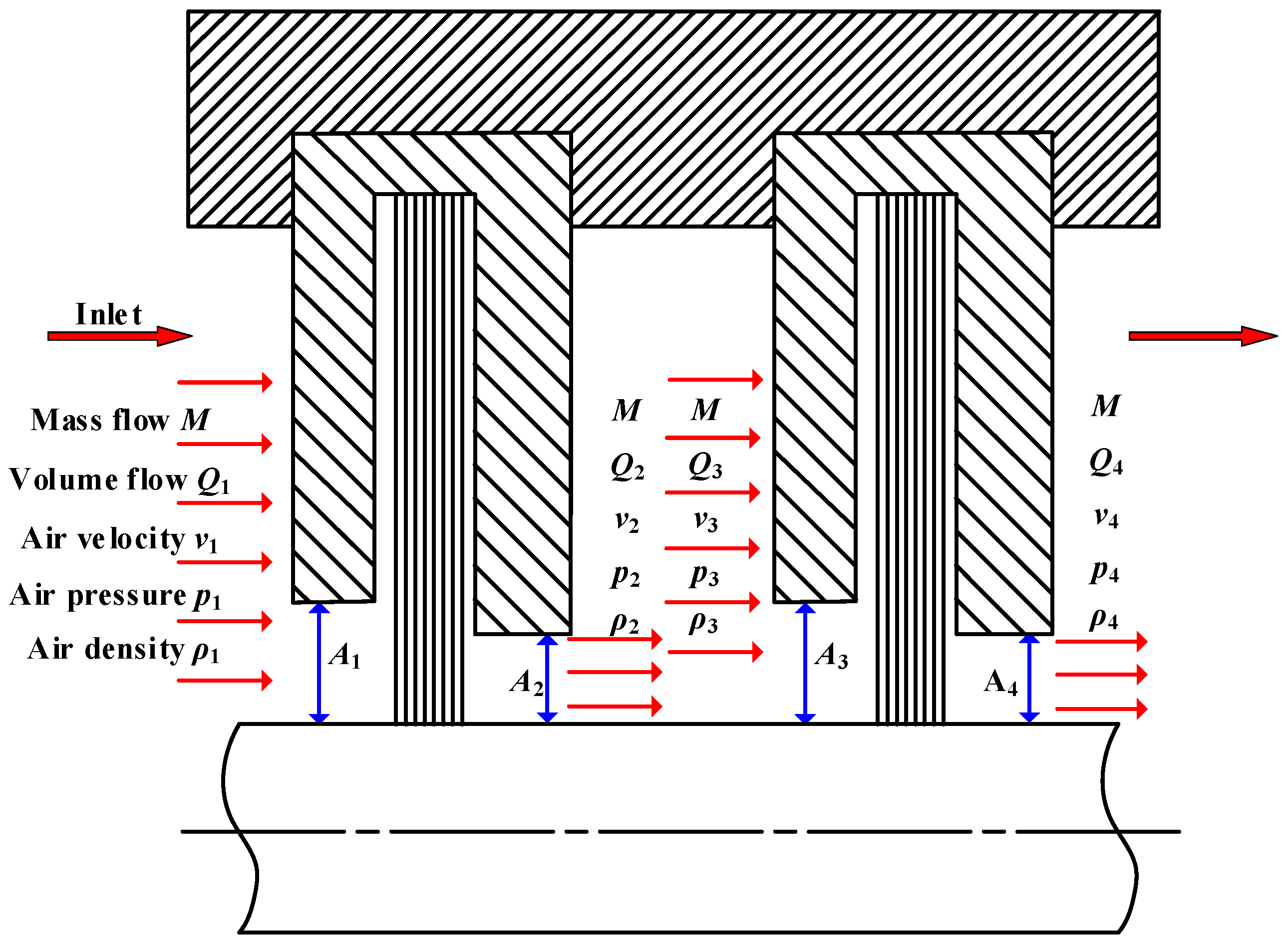
2.1. Pressure Drop Imbalance Theory of the CBS

The structure of the CBS is shown in Figure 2. It is assumed that the air flows steadily, and the loss of the air viscosity and its own gravity are ignored. The pressure drop of a certain stage and the relationship between the mass flow rate and the volume flow rate of the air of the brush seal are as follows [18]:
Δ P = 1 2 ρ 2 v 2 2 1 2 ρ 1 v 1 2
M = ρ Q = ρ v A
where M is the mass flowrate of air, Q is the volume flowrate of air, ρ is the density of air, v is the velocity of air, and A is the passage area of air.
By substituting Equation (2) into Equation (1), the inter-stage pressure drop of the first stage is as follows:
Δ P 1 = M 2 Q 2 A 2 2 Q 1 A 1 2
Similarly, the inter-stage pressure drop of the second stage is as follows:
Δ P 2 = M 2 Q 4 A 4 2 Q 3 A 3 2
where Q1, Q2, Q3 and Q4 are the inlet volume flowrate of first stage, outlet volume flowrate of first stage, inlet volume flowrate of second stage and outlet volume flowrate of second stage, respectively. A1, A2, A3 and A4 are the inlet passage area of first stage, outlet passage area of first stage, inlet passage area of second stage and outlet passage area of second stage, respectively. In addition, A1 = A3, A2 = A4.
The pressure drop balance ratio σ between the second stage and the first stage of the two-stage brush seal is defined as follows:
σ = Δ P 2 Δ P 1 = A 1 A 2 2 Q 4 Q 3 A 1 A 2 2 Q 2 Q 1
The closer σ is to 1, the more even the pressure drop distribution is. Let L = A1/A2, and the following equation is obtained:
σ = Δ P 2 Δ P 1 = L 2 Q 4 Q 3 L 2 Q 2 Q 1
The volume flow increment of the first stage and second stage are the following, respectively:
Δ Q 1 = Q 2 Q 1
Δ Q 2 = Q 4 Q 3
When the air flows through the multi-stage brush seal, the volume flow increment of each stage increases with the increase in the number of stages [18]. So, for the two-stage brush seal, there is the following:
Δ Q 2 > Δ Q 1
( Q 4 Q 2 ) ( Q 3 Q 1 ) > 0
Since A 1 > A 2 , then L > 1 , and the following can be applied:
L 2 ( Q 4 Q 2 ) ( Q 3 Q 1 ) > 0
Therefore, it can be further obtained:
L 2 Q 4 Q 3 > L 2 Q 2 Q 1
According to Equation (6), the following can be obtained:
Δ P 2 > Δ P 1
σ > 1
According to Equations (13) and (14), it can be seen that the inter-stage pressure drop of the second stage of the CBS is greater than that of the first stage, so the inter-stage pressure drops of the CBS are uneven.

2.2. Design Principle of the NBS

According to Equations (4) and (5), it can be seen that increasing the passage area of the second stage can reduce the inter-stage pressure drop of the second stage and balance the inter-stage pressure drop. Therefore, in this paper, a novel two-stage pressure-equalizing brush seal with PE hole in the second stage was presented to improve the uneven pressure drop distribution of the CBS. The two-dimensional structure diagram of the NBS is shown in Figure 3. The NBS was mainly composed of a traditional single-stage brush seal and a single-stage brush seal with PE hole in the backing plate in series; the PE hole was arranged on the backing plate of the second-stage brush seal.

3. Calculation Model

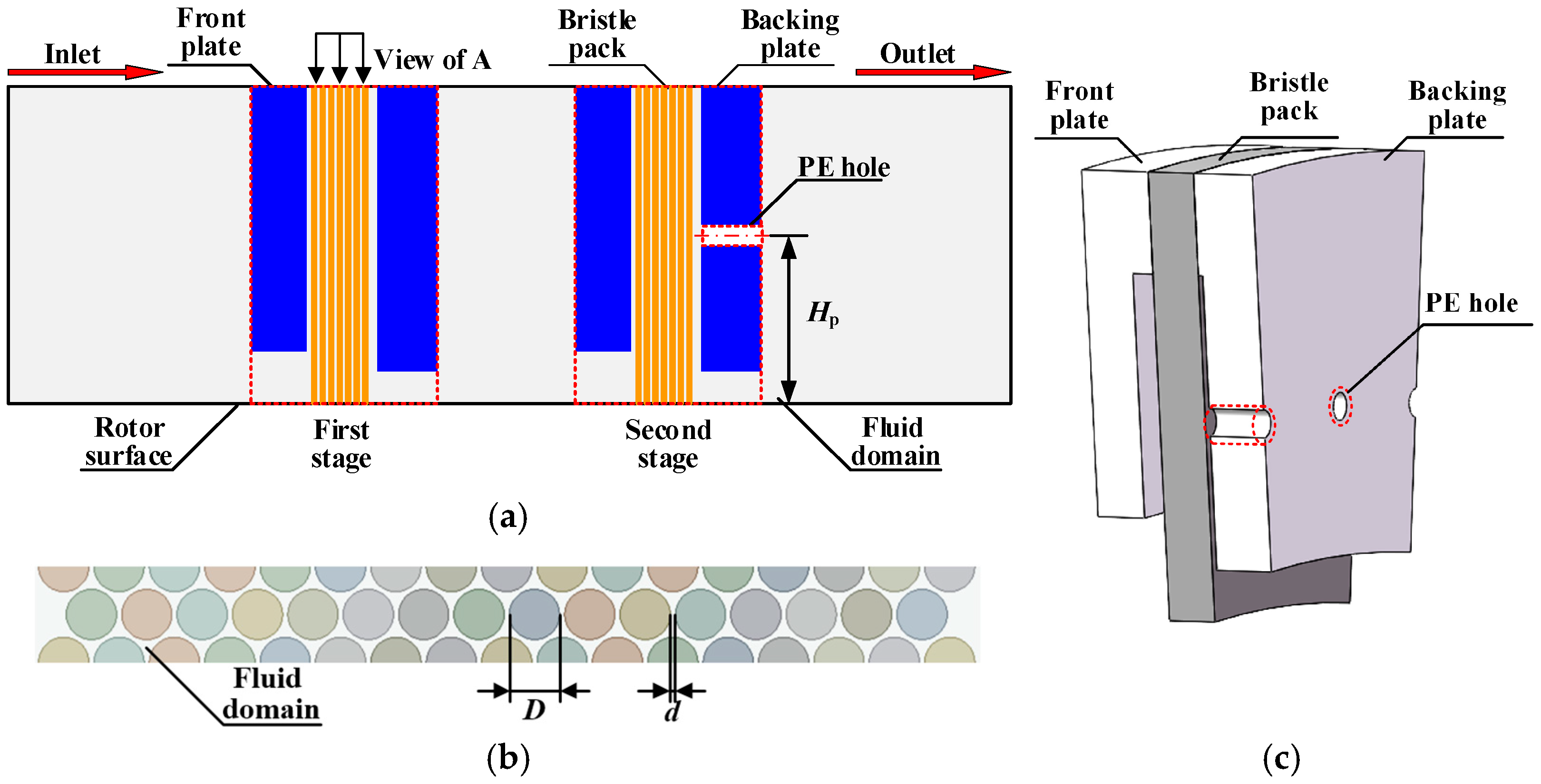
3.1. Numerical Model of NBS

In this paper, a numerical model was established based on the structure in Section 2.2, and the effects of structural parameters on pressure drop balance was studied. As shown in Figure 4, a simplified three-dimensional solid model of the NBS was established. During the actual calculation, the area below the fixed end of the bristle pack was selected as the modeling area, and the minimum cycle period consisted of a row of bristles and two half rows of bristles. The structural parameters of the NBS are shown in Table 1.

3.2. Meshing

The bristle pack and flow domains were meshed into tetrahedral and hexahedral mesh, respectively, and the meshes at the bristle pack and fluid domain at the PE hole are further encrypted. Moreover, in view of computing resources and calculation accuracy, the appropriate number of meshes should be selected. As shown in Table 2, the calculation accuracy can be ensured when the number of meshes is 5.46 million, and the meshing is shown in Figure 5. The number of meshes of many models calculated in this paper was between 5.17 million and 5.75 million.

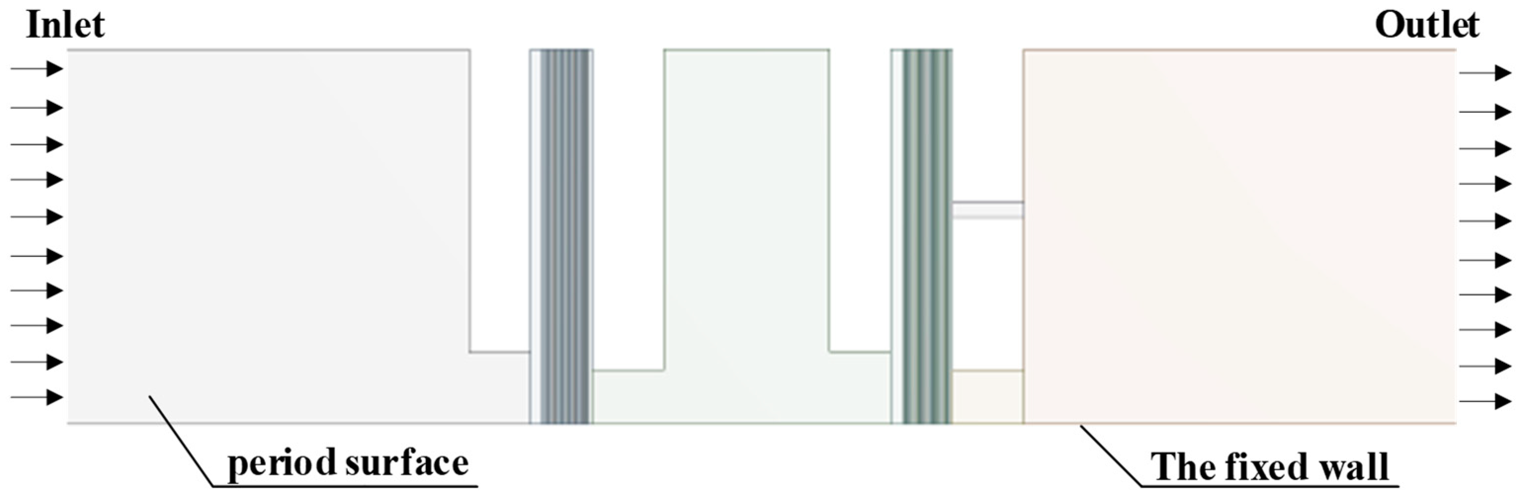
3.3. Boundary Conditions

In this paper, the ideal air is used for calculation, and the temperature is 290 K. The total pressure boundary condition is set on the inlet surface of the fluid domain, the static pressure boundary condition is set on the outlet surface and the periodic boundary conditions are set on both sides, as shown in Figure 6. Considering the numerical calculation speed and the accuracy of the flow solution outside bristles, the RNG k-ε turbulence model is used in the fluid domain [20]. In the solution setting, the total step is set to 3000 steps, and the residual is set to 10−6. The operating parameters of the model are shown in Table 3.

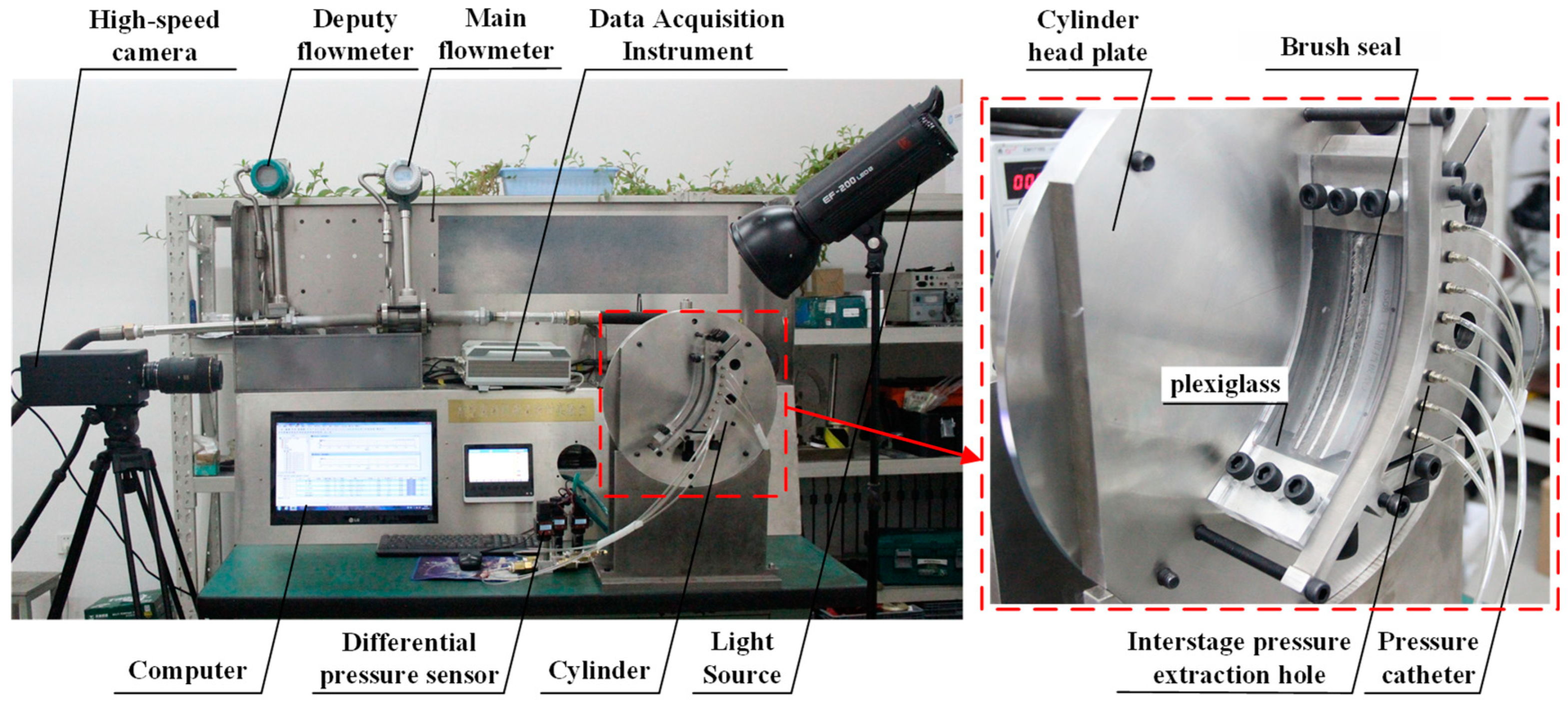
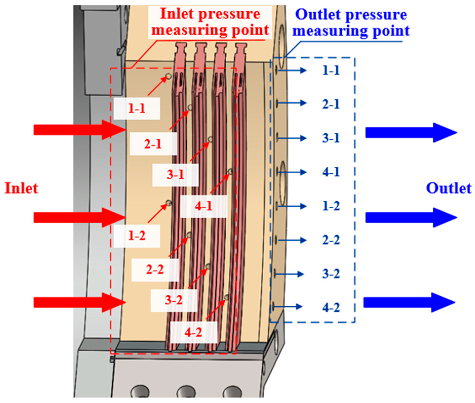
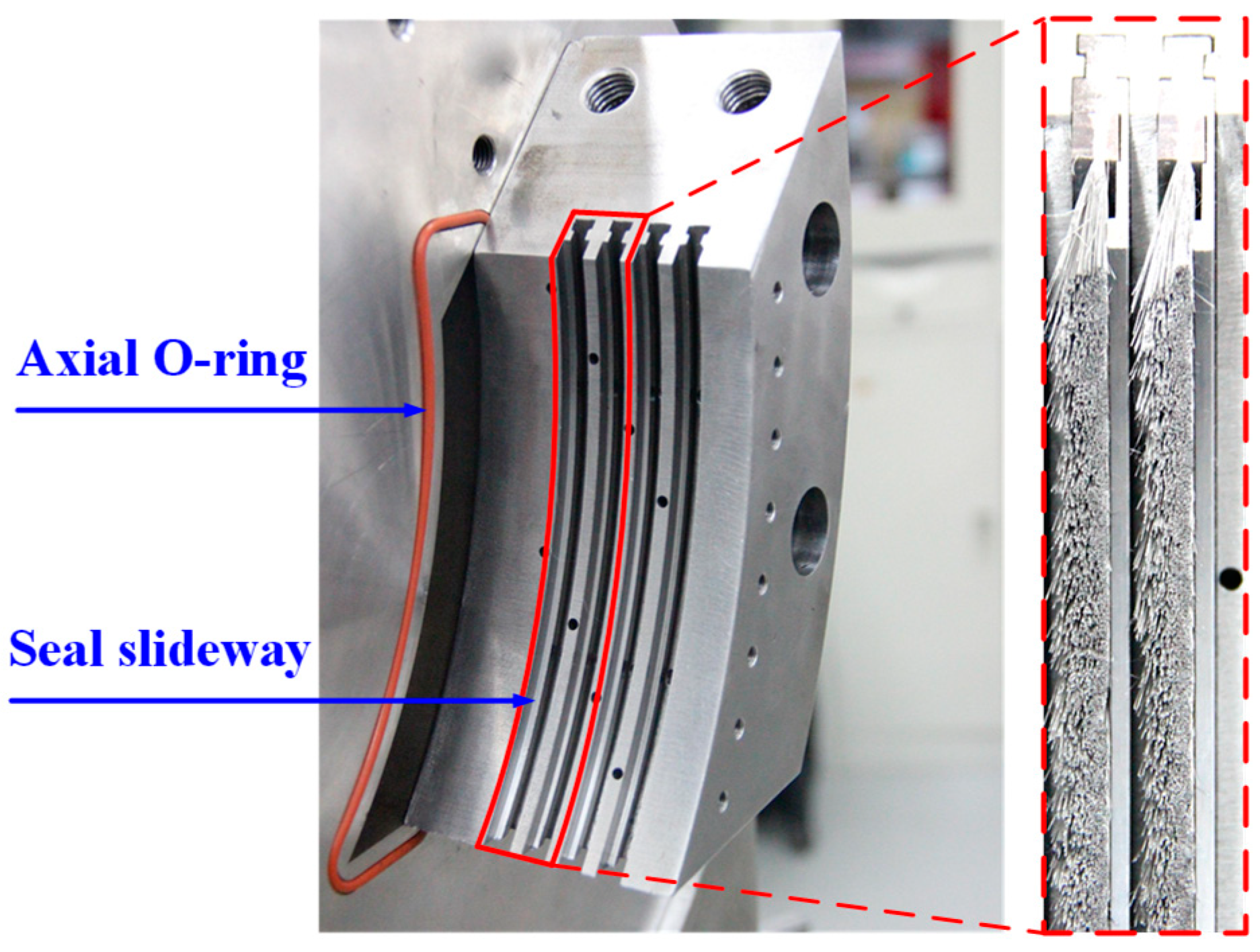
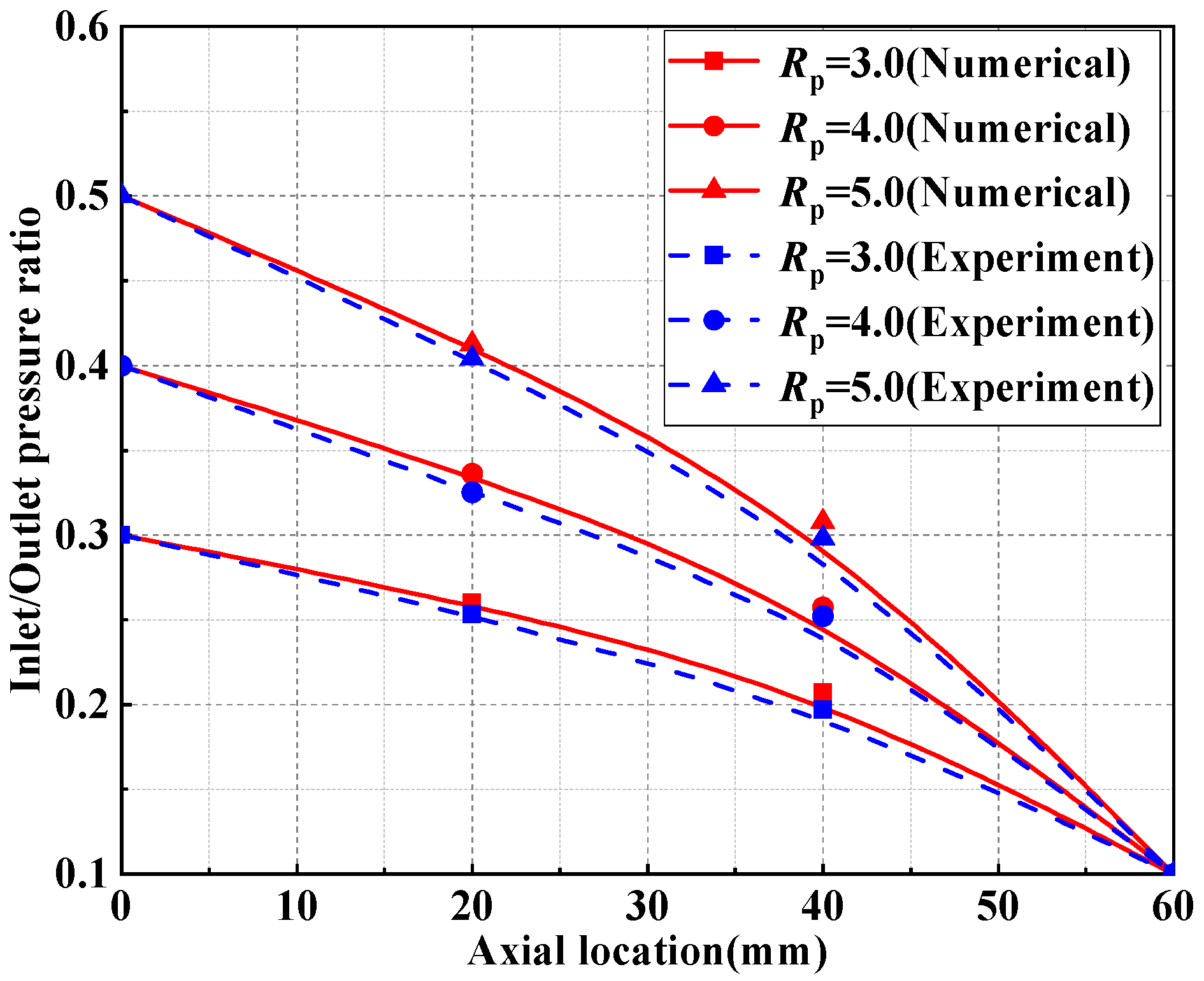
3.4. Validation of the Numerical Model

In order to be able to check whether the model reflects reality accurately, an experimental device for the leakage flow characteristics and pressure drop distribution characteristics of the brush seal was designed and built, as shown in Figure 7. The test bench adopted a one-sided inlet and one-sided outlet. The pressure was provided by the air compressor, and the maximum available pressure was 1 MPa. The gas was compressed by the air compressor and entered the cold dryer for drying treatment, then flowed into the flow path. This verification took the three-stage brush seal structure as the research object, and compared the results obtained by the experiment with the calculation results of the three-dimensional solid method in this paper to verify the accuracy of the numerical method. The experimental principle diagram of pressure drop distribution characteristics of the brush seal is shown in Figure 8. There were two inlet pressure measuring points at the upper and lower entrances of each single-stage brush seal unit. The two pressure measuring points at the upper and lower levels of each stage were one group, and there were four groups in total. At the outlet end, there were four groups of outlet pressure measuring points corresponding to the inlet pressure measuring points. In the pressure drop measuring device, the gas flowed from the inlet pressure measuring points and flowed out of the corresponding outlet pressure measuring points at the end of the base through the bristle pack, and further led the gas into the differential pressure sensor by the flexible ducts, which was used to measure the inter-stage pressure drop of the multi-stage brush seal. The differential pressure sensor was connected with the data acquisition instrument, and the data of each pressure measuring point were collected on the computer. The average value of the data of two pressure measuring points in each group was taken as the inter-stage pressure at this position. The difference between the upstream and downstream inter-stage pressures of a brush seal was the pressure drop between the brush seal stages. A photo of the brush seal test piece is shown in Figure 9, in which the axial sealing ring is used to reduce the leakage path, and the sealing slide is used to fix and replace the brush seal.
The numerical model of the same structure as the brush seal experimental piece was established by using the numerical simulation method in Section 3.1, Section 3.2 and Section 3.3. Then, the calculation results of the leakage characteristics and pressure drop distribution characteristics of the brush seal were compared with the experimental results, and the results are shown in Figure 10 and Figure 11. The maximum errors between the calculated values of leakage and pressure drop and experimental results were 7.4% and 5.8%, respectively. It shows that the numerical model can simulate the leakage characteristics and pressure drop distribution characteristics very well.

4. Analysis of the Effects of Structural Parameters on the Inter-Stage Pressure Drop Balance of NBS

4.1. Effects of PE Hole Diameter on Inter-Stage Pressure

The proportion of pressure drop Ppd is the ratio of each stage pressure drop to total pressure drop of the multi-stage brush seal [18]. The effects of PE hole diameter on inter-stage pressure are shown in Figure 12 when the pressure ratio is 3 and the height of the PE hole is 5.59 mm. As seen in Figure 12a, the proportion of second-stage pressure drop of the CBS was 25.8% higher than first-stage pressure drop. The larger second-stage pressure drop can lead to a large load on the second-stage bristles, which can lead to early failure of the second-stage bristles and the shortened service life of the CBS. The balance of inter-stage pressure drop of the NBS was obviously better than that of the CBS, and as the PE hole diameter increased, the proportion of the second-stage pressure drop gradually decreased. When the PE hole diameter was less than 0.4 mm, the proportion of the second-stage pressure drop was greater than that of the first stage. When the PE hole diameter increased to 0.6 mm, the proportion of the second-stage pressure drop was less than that of the first stage.
It can be seen in Figure 12b that the pressure drop balance ratio of the CBS and four kinds of NBSs with different PE hole diameters were 1.695, 1.262, 1.016, 0.805 and 0.776, respectively. When the PE hole diameter increased from 0.2 mm to 0.8 mm, the pressure drop balance ratio gradually decreased. In addition, when the PE hole diameter was 0.4 mm, the pressure drop balance ratio was closest to 1, and the distribution of the pressure drop was most even. This is because when the PE hole diameter is large, the passage area of second-stage outlet of the NBS is too large, which leads to the decrease in the second-stage pressure drop or even less than that of the first stage. Therefore, when the PE hole diameter was 0.4 mm, it was the best choice for the five structures.

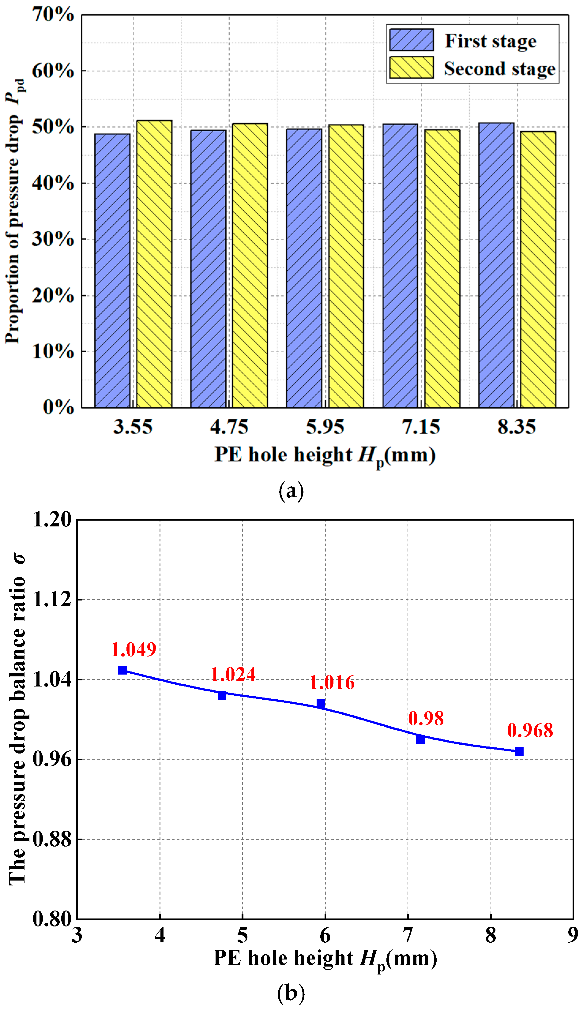
4.2. Effects of PE Hole Height on Inter-Stage Pressure

When the diameter of the hole is 0.4 mm, it can be seen in Figure 13a that the proportions of each stage pressure drop with five different PE hole heights were approximate, but the second-stage pressure drop decreases with the increase in the PE hole height. The effects of the PE hole height on the pressure drop balance ratio is shown in Figure 13b. The pressure drop balance ratio of the five kinds of PE hole heights were 1.049, 1.024, 1.016, 0.98 and 0.968, respectively. The pressure drop balance ratio gradually decreased as the PE hole height increased from 3.55 mm to 8.35 mm. In addition, when the PE hole height was 5.59 mm, the inter-stage pressure distribution was most even. Because when the PE hole height is low, the velocity of the air at the PE hole outlet is larger than that when the PE hole height is high, more air passes through the PE hole, and the volume flow increment of the second stage is larger. Therefore, the proportion of the second-stage pressure drop decreased with the increase in the PE hole height, and when the PE hole height was 5.59 mm, it was the best choice for the five structures.

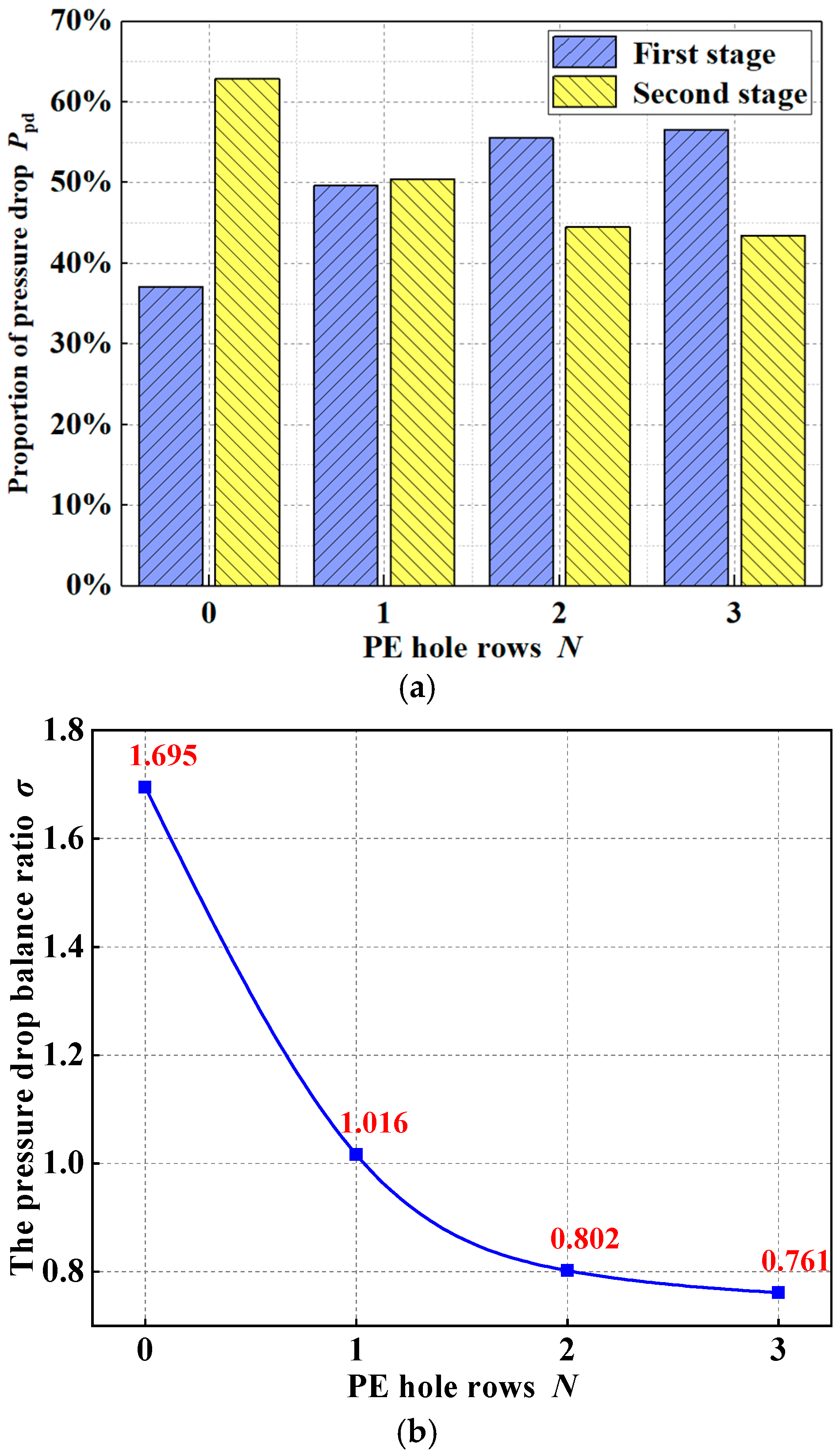
4.3. Effects of PE Hole Rows on Inter-Stage Pressure

The effects of PE hole rows on inter-stage pressure are shown in Figure 14. When the pressure ratio was 3, the PE hole diameter was 0.4 mm and the PE hole height was 5.59 mm; as seen in Figure 14a, the proportion of the second-stage pressure drop decreased gradually with the increase in the PE hole rows. When the PE hole rows were 3, the pressure drop of the first-stage accounted for 13.2% higher than that of second-stage, and the balance of inter-stage pressure drop was poor. As seen in Figure 14b, the pressure drop balance ratio of the CBS and three kinds of the PE hole rows were 1.695, 1.016, 0.802 and 0.761, respectively. When the rows of PE hole were 1, the inter-stage pressure drop distribution was the most even.

4.4. Analysis of Pressure Distribution Characteristics of NBS

It can be seen from the above research that when the PE hole diameter was 0.4 mm, the height was 5.95 mm and the number of rows was 1, the new structure had the best pressure drop balance. Therefore, this section aims to analyze the pressure distribution characteristics of this optimized structure compared with the CBS.
The axial pressure distribution of the CBS and NBS under the pressure ratio of 3 is shown in Figure 15. It can be seen in Figure 15 that when the air flowed from upstream to downstream, the pressure drop mainly occurred in the area of the bristle pack. The pressure of the first-stage last bristles of the NBS was obviously smaller than that of the CBS, which proved that the pressure distribution of the NBS was more even. This is because the passage area of the second-stage brush seal is increased compared to the CBS, which can reduce the pressure of second-stage, and balance the inter-stage pressure drop of the NBS.
The comparison of pressure values at different positions of two structures with the pressure ratio of 3.0~5.0 is shown in Figure 16. When the air flowed through the brush seal, the pressure decreased along the axial direction. The pressure drop mainly occurred in the bristle pack, and the second-stage pressure drop of the CBS was obviously larger than that of the first stage. However, the inter-stage pressure drop of the NBS was approximately average, which proved that the NBS effectively improved the uneven pressure drop distribution among stages.

5. Analysis of Flow Field of NBS

The structural parameters with optimal pressure drop balance was determined in Section 4.4. In order to further determine the feasibility of this structure, the most important leakage flow characteristics of the brush seal are studied in this chapter. In this section, the leakage flow characteristics of the NBS were analyzed when the pressure ratio was 3, the PE hole diameter was 0.4 mm, the height was 5.95 mm, and the number of rows was 1.

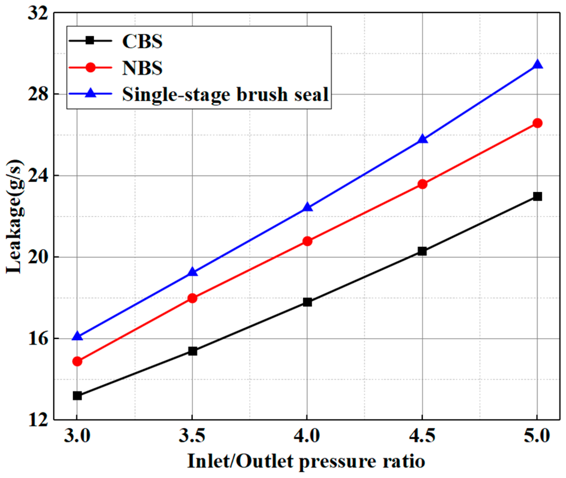
5.1. Analysis of Leakage Characteristics of NBS

The comparison of leakage between the NBS and CBS and the single-stage brush seal is shown in Figure 17. The leakage of the NBS increased with the increase in pressure ratio, and it was approximately linear with the increment of pressure ratio. However, when the pressure ratios were the same, the leakage of the NBS was greater than that of the CBS, and compared to the CBS, the NBS had a larger growth trend of leakage. This is because the PE hole increases the air outlet channel, which makes part of the air flow out from the PE hole and increase the leakage. The leakage of the NBS is 12.9~16.8% higher than that of the CBS, which has a certain impact on the sealing performance, but the leakage of the NBS is still less than that of the single-stage brush seal.

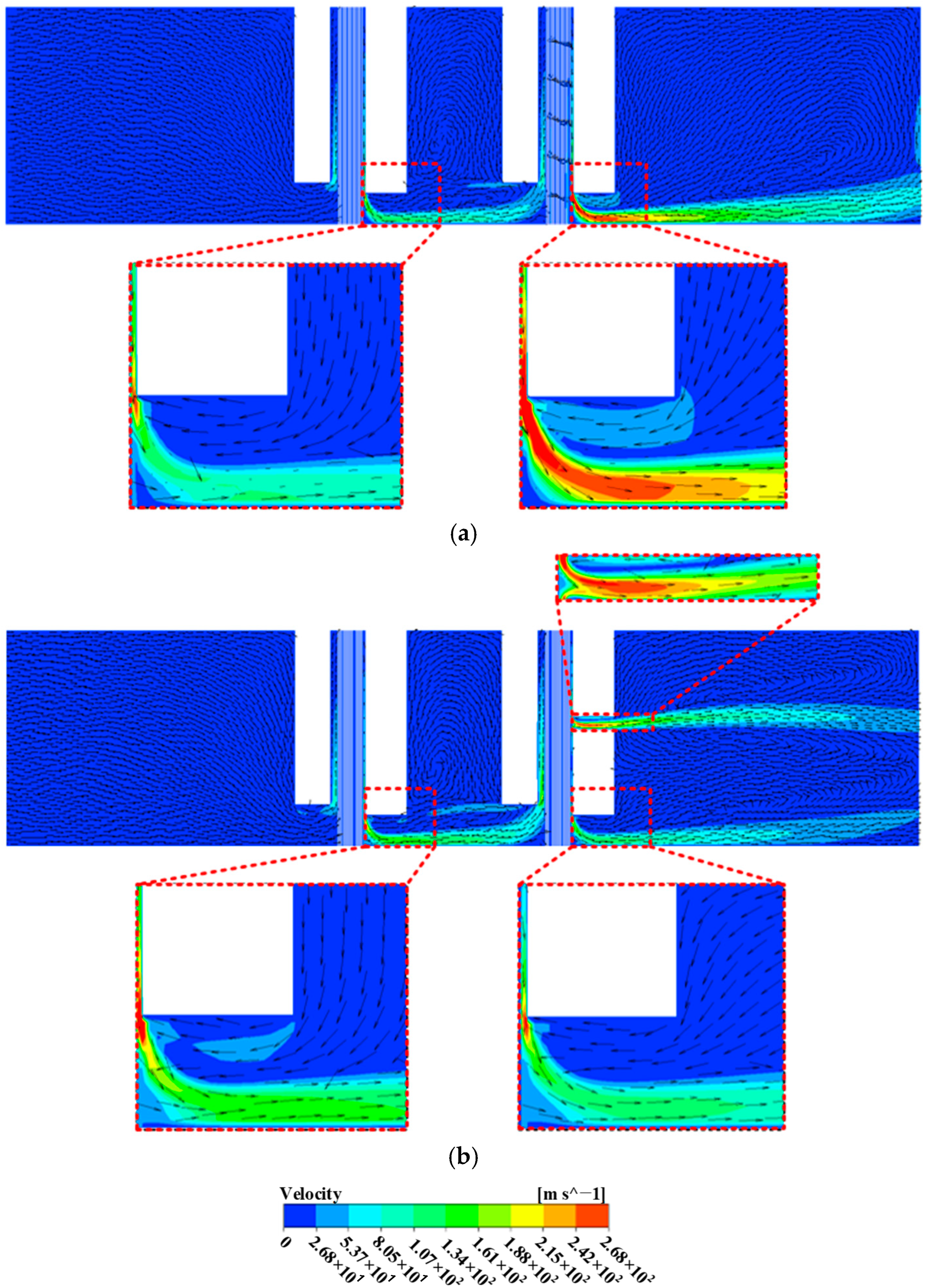
5.2. Analysis of Air Velocity Distribution Characteristics of NBS

With a pressure ratio of 3, a PE hole diameter of 0.4 mm, a height of 5.95 mm and a number of rows of 1, the axial air velocity distribution of the CBS and NBS is shown in Figure 18. The air of two structures both formed jets near the backing plate, and the air of the NBS also formed a high-speed jet at the PE hole. The maximum air velocity of the CBS occurred near the second-stage backing plate, but the maximum air velocity of the NBS occurred at the PE hole, and the maximum flow velocity of the NBS is smaller than that of the CBS. Because the NBS increases the passage area of air, its maximum flow velocity is less than that of the CBS. However, since the PE hole diameter is less than the height of backing plate to rotor, the maximum velocity of the air occurs at the PE hole. Moreover, both structures generate vortex flow in the inter-stage chamber.
Based on the above working conditions and structure, the radial cross-section velocity downstream of the bristle pack is selected as shown in Figure 19. It can be observed that the axial and radial flow trends of the CBS and NBS brush seals are stronger, while the circumferential flow trend is weaker. The radial flow trend of the CBS on the downstream surface of the bristle pack is stronger than the axial flow trend, while the axial flow trend of the NBS around the PE hole and inside the bristle pack is stronger. Since the radial air preferentially flows into the PE hole, the radial flow trend of the air below the PE hole is weaker than that of the CBS.

6. Conclusions

In this paper, according to the theory of pressure drop balance, a novel two-stage pressure-equalizing brush seal was proposed. Then, the influence of structural parameters on the inter-stage pressure drop balance of the NBS was studied, and the new structure with the best pressure drop balance was obtained. Finally, the leakage flow characteristics of the NBS were studied. The following conclusions were reached:
(1)
The NBS increased the effective flow area of the second-stage brush seal, and the inter-stage pressure drop was more even. Therefore, the NBS effectively balanced the inter-stage pressure drop of the CBS. Under the structural parameters studied in this paper, the pressure drop balance ratio of the NBS is improved by 45.6~67.9% compared to the CBS.
(2)
The PE hole diameter, rows and PE hole height were found to enhance the pressure drop uniformity. The pressure drop balance ratio was greatly affected by the PE hole diameter and rows, and was less affected by the PE hole height. When the PE hole diameter was 0.4 mm, the height was 5.95 mm and the number of rows was 1, the NBS had the best pressure drop balance.
(3)
The PE hole expands the air outlet channel and outflow area, resulting in a 12.9~16.8% increase in NBS leakage relative to CBS. However, this phenomenon does not only constitute damage. On the contrary, the PE hole alleviates the problem of uneven pressure drop between CBS stages, which is beneficial to improve the service life of the two-stage brush seal. From a comprehensive perspective, the solution based on nature proposed in this paper has a certain practicability in practical engineering applications.

Author Contributions

Conceptualization, Y.L.; Methodology, J.Z. and Z.Y.; Software, Y.L., H.X., J.Z. and Z.Y.; Validation, H.X.; Data curation, J.Z.; Writing—original draft, H.X.; Writing—review & editing, Y.L., D.S. and Z.Y.; Supervision, D.S.; Project administration, D.S.; Funding acquisition, D.S. All authors have read and agreed to the published version of the manuscript.

Funding

This research was funded by the National Natural Science Foundation of China (Grant Nos. 52075346 and 52375195). This research was supported by Industry-University Research Cooperation Project of China Aeroengine Group (Grant No. HFZL2021CXY012).

Data Availability Statement

The original contributions presented in the study are included in the article, further inquiries can be directed to the corresponding author.

Conflicts of Interest

The authors declare no conflict of interest.

Nomenclature

CBScommon two-stage brush seal
NBSnovel two-stage pressure-equalizing brush seal
ΔP1, ΔP2pressure drop of the first stage and second stage of the two-stage brush seal, MPa
σpressure drop balance ratio
Lratio between passage areas at inlet and outlet of the stage
ΔQ1, ΔQ2volume flow increment of first stage and second stage of the two-stage brush seal
Hfheight of front plate to rotor, mm
Hbheight of backing plate to rotor, mm
Dbristle diameter, mm
dbristle gap, mm
Waxial width of bristle pack, mm
lbristle length, mm
Lfaxial width of front plate, mm
Lbaxial width of backing plate, mm
DpPE hole diameter, mm
HpPE hole height, mm
NPE hole rows
Rppressure ratio
Ppdproportion of pressure drop

References

  1. Fuchs, A.; Haidn, O.J. Effects of Uncertainty and Quasi-Chaotic Geometry on the Leakage of Brush Seals. J. Turbomach. 2019, 141, 021003. [Google Scholar] [CrossRef]
  2. Ha, Y.; Ha, T.; Byun, J.; Lee, Y. Leakage effects due to bristle deflection and wear in hybrid brush seal of high-pressure steam turbine. Tribol. Int. 2020, 150, 106325. [Google Scholar] [CrossRef]
  3. Hildebrandt, M.; Schwitzke, C.; Bauer, H.J. Analysis of Heat Flux Distribution during Brush Seal Rubbing Using CFD with Porous Media Approach. Energies 2021, 14, 1888. [Google Scholar] [CrossRef]
  4. Wei, Y.; Ran, X.H.; Sun, T.; Liu, S.L.; Zhang, H.L.; Zhao, D.F. Dynamic characteristics analysis of a vertical Jeffcott rotor-brush seal system. J. Chin. Inst. Eng. 2022, 45, 245–254. [Google Scholar] [CrossRef]
  5. Chupp, R.E.; Ghasripoor, F.; Turnquist, N.A.; Demiroglu, M.; Aksit, M.F. Advanced seals for industrial turbine applications: Dynamic seal development. J. Propul. Power 2002, 18, 1260–1266. [Google Scholar] [CrossRef]
  6. Changizi, A.; Stiharu, I.; Outirba, B.; Hendrick, P. Mathematical model of brush seals for gas turbine engines: A nonlinear analytical solution. Adv. Mech. Eng. 2021, 13, 16878140211043396. [Google Scholar] [CrossRef]
  7. Liu, Y.X.; Dong, W.L.; Chew, J.; Pekris, M.; Yue, B.Z.; Kong, X.Z. Flow Conditioning to Control the Effects of Inlet Swirl on Brush Seal Performance in Gas Turbine Engines. Front. Energy Res. 2022, 9, 815152. [Google Scholar] [CrossRef]
  8. Lee, J.J.; Kang, S.Y.; Kim, T.S.; Byun, S.S. Thermo-economic analysis on the impact of improving inter-stage packing seals in a 500 MW class supercritical steam turbine power plant. Appl. Therm. Eng. 2017, 121, 974–983. [Google Scholar] [CrossRef]
  9. Addis, M.E.; Dalton, W.S. Brush-Seal Designs for Elastic Fluid Turbines. U.S. Patent No. 6,318,728, 20 November 2001. [Google Scholar]
  10. Tseng, W.Y.; Bristol, B.L.; Hetico, R.R.; Glynn, C.C. Brush Seal. U.S. Patent No. 5,568,931, 29 October 1996. [Google Scholar]
  11. Tanimura, K. Apparatus for Sealing a Channel. EP Patent No. 2,305,956, 28 February 2018. [Google Scholar]
  12. Naert, A.; Durieu, F. Turbomachine Axial Compressor Seal with a Brush Seal. U.S. Patent No. 20,150,063,990, 5 March 2015. [Google Scholar]
  13. Chupp, R.E.; Dowler, C.A. Performance Characteristics of Brush Seals for Limited-Life Engines. J. Eng. Gas Turbines Power 1993, 115, 390–396. [Google Scholar] [CrossRef]
  14. Hendricks, R.C.; Griffin, T.A.; Kline, T.R.; Kline, R.C.; Arvind, P.; Dvandra, S. Relative Performance Comparison Between Baseline Labyrinth and Dual Brush Compressor Discharge Seals in a T-700 Engine Test. In Proceedings of the ASME 1994 International Gas Turbine and Aeroengine Congress and Exposition, The Hague, The Netherlands, June 13–16 1994; pp. 1–21. [Google Scholar] [CrossRef]
  15. Pugachev, A.O.; Deckner, M. Experimental and theoretical rotordynamic stiffness coefficients for a three-stage brush seal. Mech. Syst. Signal Process. 2012, 31, 143–154. [Google Scholar] [CrossRef]
  16. Qiu, B.; Li, J.; Yan, X. Investigation into the flow behavior of multi-stage brush seals. Proc. Inst. Mech. Eng. Part A J. Power Energy 2014, 228, 416–428. [Google Scholar] [CrossRef]
  17. Yang, J.; Huang, S.Q.; Suo, S.F.; Wang, A.M. Investigating the frictional force distributions and inter-stage imbalance of a two-stage brush seal. AIP Adv. 2020, 10, 035323. [Google Scholar] [CrossRef]
  18. Zhao, H.; Li, Y.L.; Sun, D.; Li, Y.; Wen, S.F.; Sun, J.S. Inter-Stage Pressure Drop of Multi-Stage Brush Seal with Differentiated Structure. J. Eng. Gas Turbines Power 2023, 145, 071001. [Google Scholar] [CrossRef]
  19. Sun, D.; Yang, Y.X.; Zhao, H.; Zhang, J.Y.; Yang, Z.M.; Zhang, J.H. Influence factors of frictional heat between bristles and rotor for a multi-stage brush seal. Tribol. Int. 2024, 198, 109841. [Google Scholar] [CrossRef]
  20. Yakhot, V.; Orszag, S.A.; Thangam, S.; Gatski, T.B.; Speziale, C.G. Development of turbulence models for shear flows by a double expansion technique. Phys. Fluids 1992, 4, 1510–1520. [Google Scholar] [CrossRef]
Figure 1. Multi-stage brush seal structure diagram: (a) Traditional multi-stage brush seal; (b) Low hysteresis multi-stage brush seal; (c) Multi-stage brush seal with axial tilt; (d) Multi-stage brush seal with first-stage vibration-suppression elastic piece; (e) Multi-stage brush seal with inter-stage exhaust channel; (f) Multi-stage brush seal with radial arrangement of bristles.
Lubricants 13 00190 g001
Figure 2. Schematic diagram of CBS.
Lubricants 13 00190 g002
Figure 3. Two-dimensional structure diagram of NBS.
Lubricants 13 00190 g003
Figure 4. Numerical solution model of NBS: (a) Overall diagram of the model; (b) View of A; (c) View of PE hole.
Lubricants 13 00190 g004
Figure 5. Mesh of NBS: (a) Global mesh diagram; (b) View of A.
Lubricants 13 00190 g005
Figure 6. Boundary conditions.
Lubricants 13 00190 g006
Figure 7. Experimental device for leakage flow characteristics and pressure drop distribution characteristics of brush seal.
Lubricants 13 00190 g007
Figure 8. Experimental principle of brush seal pressure drop distribution characteristics.
Lubricants 13 00190 g008
Figure 9. Photo of brush seal test piece.
Lubricants 13 00190 g009
Figure 10. Comparison verification results of the leakage.
Lubricants 13 00190 g010
Figure 11. Comparison verification results of the pressure drop.
Lubricants 13 00190 g011
Figure 12. Effects of PE hole diameter on pressure drop distribution between the two-stage brush seal: (a) proportion of pressure drop; (b) pressure drop balance ratio.
Lubricants 13 00190 g012
Figure 13. Effects of PE hole height on pressure drop distribution between the two-stage brush seal: (a) proportion of pressure drop; (b) pressure drop balance ratio.
Lubricants 13 00190 g013
Figure 14. Effects of PE hole rows on pressure drop distribution between the two-stage brush seal: (a) proportion of pressure drop; (b) pressure drop balance ratio.
Lubricants 13 00190 g014
Figure 15. Axial pressure distribution of CBS and NBS: (a) CBS; (b) NBS.
Lubricants 13 00190 g015
Figure 16. Comparison of inter-stage pressure between CBS and NBS.
Lubricants 13 00190 g016
Figure 17. Comparison of leakage between NBS and CBS and single-stage brush seal.
Lubricants 13 00190 g017
Figure 18. Air velocity distribution of CBS and NBS: (a) CBS; (b) NBS.
Lubricants 13 00190 g018
Figure 19. Air velocity distribution in radial section: (a) CBS; (b) NBS.
Lubricants 13 00190 g019
Table 1. Structural parameters of NBS.
Structural ParametersValues
Height of front plate to rotor Hf (mm)2.0
Height of backing plate to rotor Hb (mm)1.5
Bristle diameter D/mm0.08
Bristle gap d/mm0.008
Axial width of bristle pack W/mm1.5
Bristle length l/mm10.4
Axial width of front plate Lf/mm1.5
Axial width of backing plate Lb/mm2
PE hole diameter Dp/mm0.2, 0.4, 0.6, 0.8
PE hole height Hp/mm3.55, 4.75, 5.95, 7.15, 8.35
PE hole rows N1, 2, 3
Table 2. Mesh independence verification.
Number of Grids/Ten ThousandLeakage (g/s)
30114.62
38214.43
45814.08
54613.84
59013.84
Table 3. Boundary conditions of numerical model.
Working Condition ParametersValues
FluidIdeal air
Turbulence modelRNG k-ε
Inlet total pressure/MPa0.3, 0.4, 0.5
Outlet static pressure/MPa0.1
Inlet temperature/K290
Rotational speed/(r·min−1)3000
Disclaimer/Publisher’s Note: The statements, opinions and data contained in all publications are solely those of the individual author(s) and contributor(s) and not of MDPI and/or the editor(s). MDPI and/or the editor(s) disclaim responsibility for any injury to people or property resulting from any ideas, methods, instructions or products referred to in the content.

