Abstract
With the development of steel sheets towards higher strength and lower thickness, the process of rolling is facing more challenges, and one of the most important issues is lubrication, which directly determines the rolling stability, product quality, and production efficiency. This study focuses on the modeling and analysis of oil film thickness with viscosity–pressure–temperature (VPT) coupling effects under a hybrid lubrication system. Firstly, the mechanisms and limitations of direct spray and recirculation lubrication systems are systematically compared, highlighting the advantages of hybrid lubrication for high-speed tandem cold rolling. Subsequently, the mathematical models corresponding to different positions within the rolling interface between the roll and strip, are presented; the initial oil film thickness is described based on both plate-out and dynamic concentration formation mechanisms under the hybrid lubrication; and the model of inlet oil film thickness integrates the Reynolds equation, VPT effects, energy conservation, and continuity equations to quantify temperature-driven viscosity degradation. Furthermore, the influences of rolling process and lubrication parameters on the oil film thickness are analyzed, and a dynamic regulation strategy is proposed to optimize direct emulsion flow with regard to the actual rolling speed and the expected oil film thickness. This work bridges the gap between theoretical models and industrial requirements, providing actionable insights for high-speed rolling of advanced high-strength steel sheets.
1. Introduction
High-strength thin sheets, characterized by their lightweight design, exceptional strength, and superior formability, are indispensable in automotive body structures, aerospace frameworks, and precision electronics. Multi-stand tandem rolling is considered a cornerstone technology for enhancing production efficiency and enabling large-scale industrial manufacturing, yet the cumulative work hardening and interfacial friction inherent to the process pose significant challenges [1]. For instance, insufficient lubrication—marked by a friction coefficient increase from 0.08 to 0.15—amplifies rolling forces by 18–25%, exacerbating mill vibrations and strip breakage risks [2,3]. These issues underscore the critical role of lubrication in balancing production efficiency, strip quality, and rolling stability [4].
Dynamic concentration theory and plate-out theory are two representative mechanisms of emulsion oil film formation. The dynamic concentration theory emphasizes shear-driven aggregation of oil droplets at the deformation zone inlet, forming transient lubricating films [5,6], while the plate-out theory focuses on emulsifier adsorption and interfacial interactions to stabilize boundary films [7,8].
The calculation of oil film thickness is intrinsically linked to the mechanisms of oil film formation. Oil film thickness models employ mathematical frameworks (e.g., the Reynolds equation and the energy equation) to quantify these physical mechanisms and predict film behavior under varying process parameters (speed, pressure, temperature, etc.). Wilson and Walowit’s classical isothermal model [9] laid the foundation for oil film thickness prediction, but its assumption of constant viscosity fails to address thermal effects. This classical model has been widely applied and demonstrates satisfactory performance under low-speed rolling conditions (<5 m/s); however, it fails to account for the viscosity degradation caused by frictional heating in high-speed rolling. For instance, when the rolling speed exceeds 15 m/s, the temperature at the roll–strip interface can reach 200–300 °C [10]. Under these conditions, the lubricant viscosity may decrease by over 50%, resulting in oil film thickness prediction errors exceeding 30% [11]. Advanced models, such as Cheng and Kiet’s mixed lubrication framework [12], incorporate surface roughness but neglect viscosity–pressure–temperature (VPT) interactions. Recent efforts by Xin and Gao [13] partially address this gap through empirical speed-dependent correlations, yet a comprehensive VPT-coupled model remains elusive.
Lubrication systems further complicate this landscape. Direct spray systems ensure fresh emulsion supply but incur high consumption and environmental costs [14], while recirculation systems prioritize sustainability but struggle with particulate contamination and delayed response [15]. Hybrid lubrication—combining both modes—offers a promising compromise, enabling high-speed rolling (e.g., 25 m/s) with friction coefficient stability (±0.02) [16]. However, existing models lack robust integration of multi-physics coupling (e.g., thermal–stress interactions), limiting their predictive accuracy under dynamic conditions [17,18].
This study makes the following contributions for high-speed rolling of high-strength thin sheets: (1) development of VPT-coupled oil film thickness models under a hybrid lubrication system; (2) numerical calculation and mechanism analysis of oil film thicknesses with temperature-driven viscosity degradation; (3) discussion of rolling process and lubrication parameters influencing oil film thickness; and (4) quantitative description of the dynamic regulation of direct emulsion flow with regard to the actual rolling speed and the expected oil film thickness.
2. Hybrid Lubrication Mode
2.1. Features of Direct Spray Lubrication and Recirculation Lubrication Modes
Direct spray and recirculation lubrication modes exhibit distinct mechanisms and limitations, as summarized in Table 1.

Table 1.
Comparison of direct spray and recirculation lubrication modes.
In direct spray lubrication, high-concentration emulsions with large oil droplets are sprayed directly onto the strip surface ahead of the rolling gap. The oil film primarily forms via the plate-out theory, where oleophilic strip surfaces adsorb oil droplets, creating a thick boundary film [7].
In recirculation lubrication, low-concentration emulsions with small droplets are sprayed onto the roll–strip interface. Oil film formation follows the dynamic concentration theory: shear forces compress droplets at the entry zone, triggering an inversion from oil-in-water to water-in-oil emulsions, which increases viscosity and forms a lubricating film [5,6].
2.2. Hybrid Lubrication for High-Speed Rolling
Direct spray mode ensures rapid lubrication and excels in high-speed scenarios, but faces environmental and cost challenges [14]. Contrarily, recirculation mode reduces waste and prioritizes cooling and sustainability, but lacks responsiveness under dynamic conditions [19]. As a result, the hybrid lubrication system synergizes direct spray and recirculation lubrication modes to address their individual limitations, enabling stable high-speed tandem cold rolling (>20 m/s) of high-strength thin sheets.
As illustrated in Figure 1, compared to recirculation-only mode, in the hybrid lubrication system, direct spray nozzles are positioned upstream and deliver high-concentration emulsions (10–15%) to the strip surface, ensuring rapid plate-out film formation; recirculation nozzles are located near the roll–strip interface and spray low-concentration emulsions (2–4%) for cooling and residual lubrication.
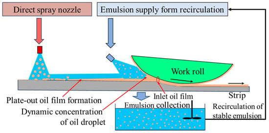
Figure 1.
Hybrid lubrication system with both direct spray and recirculation lubrication modes.
The following advantages are achieved by the hybrid lubrication mode:
- (1)
- Enhanced lubrication–cooling balance: direct spray ensures sufficient oil film thickness, while recirculation mitigates thermal runaway (interface temperature < 200 °C) [10];
- (2)
- Friction reduction: hybrid systems reduce friction coefficients by 30–40% compared to standalone recirculation, lowering rolling forces by 1.7–10.3% [20];
- (3)
- Sustainability: spent emulsions from direct spray are filtered and reused in recirculation loops, cutting oil consumption by 40–50% [14].
The adoption of hybrid lubrication systems in cold tandem rolling represents a paradigm shift in high-speed manufacturing. Recent studies have demonstrated their capability [21] to reduce edge wave incidence from 12% to 3% through real-time emulsion parameter optimization, while simultaneously achieving a 35% reduction in oil consumption and stable operation with friction coefficient fluctuations < ±0.02.
Despite these advancements, the lack of robust models for oil film thickness prediction and speed-dependent adjustment of emulsion flow rates under hybrid lubrication—particularly in scenarios requiring concurrent speed enhancement and vibration suppression—remains a barrier to full-scale industrial implementation.
3. Oil Film Thickness Under Hybrid Lubrication
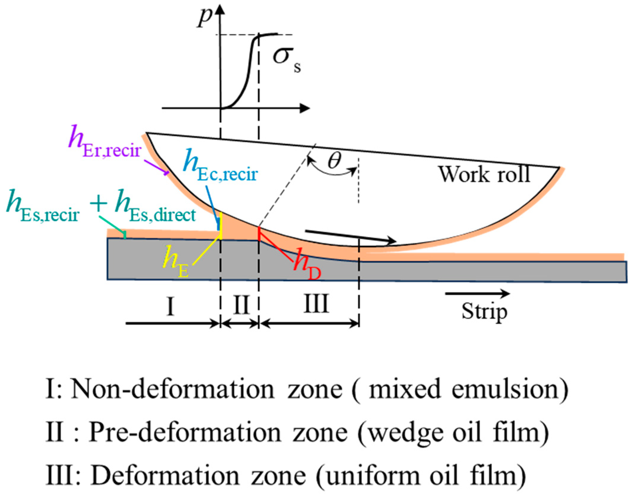
In order to describe the film formation and evolution process under hybrid lubrication, we divide the roll–strip interface into three parts, i.e., the non-deformation zone (mixed emulsion), pre-deformation zone (wedge oil film), and deformation zone (uniform oil film), as schematically illustrated in Figure 2.
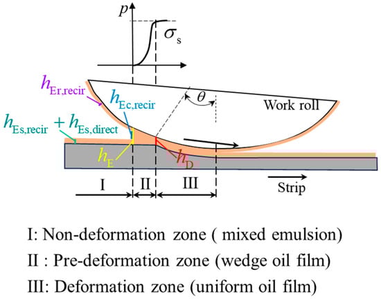
Figure 2.
Oil film formation within the interface between the roll and strip.
Within the non-deformation zone, high-concentration emulsions from direct spray nuzzles and low-concentration emulsions from recirculation nozzles coexist in the gap between strip and rolls. According to the plate-out property of the emulsion on the metal surfaces and the dynamic concentration behavior of large oil droplets, a wedge oil film is formed in the pre-deformation zone, and the oil film thickness gradually decreases with the rolling pressure increasing from zero to the deformation resistance of the strip. In the deformation zone, the oil film is assumed to be uniform and equal to the exit film thickness of the pre-deformation zone.
Based on this assumption, the oil film thickness is modeled as
Here, denotes the oil film thickness at the beginning position of the wedge pre-deformation zone; represents the oil film thickness at the end position of the wedge pre-deformation zone, and also that of the inlet position of the deformation zone; hence, the inlet oil film thickness refers to the inlet oil film thickness of the deformation zone; and is the deformation resistance of the strip.
3.1. Mathematical Model of Oil Film Thickness hE
If the oil film caused by the strip from the upstream stand is not considered, the initial oil film thickness formed by the mixed emulsions is presented as
Here, denotes the oil film thickness plated-out on the strip surface from the direct spray high-concentration emulsion. denotes the oil film thickness captured by the rolling gap via the dynamic concentration of recirculation lubrication emulsion; and and represent the oil film thicknesses plated-out on the strip and rolls from recirculation lubrication emulsion.
- (1)
- Oil film thickness from the direct spray lubrication subsystem
According to the plate-out formation mechanism of oil film, , measured in microns, is expressed as
Here, denotes the mass of oil film per unit area under direct lubrication (kg/mm2), in which individually represent the supplied emulsion flow quantity (L/min), the emulsion concentration (%), and the density of lubrication oil (kg/mm3); denotes the width of the rolled strip (m) and denotes the strip entry speed (m/s). is the plate-out efficiency and is characterized by
where denotes the reference plate-out efficiency function regressed from direct spray lubrication experiments; denotes the correction coefficient determined by strip entry speed and nozzle location; and denote the correction coefficients corresponding to varying temperature, concentration and droplet size in the actual rolling process, respectively.
- (2)
- Oil film thickness from recirculation lubrication subsystem
Firstly, is estimated by the dynamic concentration formation mechanism of oil film, i.e.,
where denotes the recirculation emulsion concentration (%); represents the capture rate of oil droplet by the rolling gap (%); and is the oil droplet size of the recirculation lubrication emulsion.
Then, similarly, via the plate-out formation mechanism of oil film, and can be respectively expressed as
Here, represent the recirculation emulsion flow quantity (mm3/s) and concentration (%); and and denote the plate-out efficiencies on strip and rolls, i.e.,
where denotes the reference plate-out efficiency function from recirculation lubrication experiments; denote the correction coefficients corresponding to varying temperature, concentration, and droplet size in the actual rolling process, respectively; and is introduced to express the reserved efficiency related to the surface state of rolls.
3.2. Modeling and Solving Method of Inlet Oil Film Thickness hD
Based on the assumption of the incompressible Newtonian fluid, the unknown inlet oil film thickness is expected to be calculated via the Reynolds equation applied to long bearing approximation [22], i.e.,
Here, and denote the rolling pressure and the oil film thickness at the arbitrary position within the wedge pre-deformation zone; is the rolling speed; and denotes the viscosity of the lubricant oil.
- (1)
- Viscosity–pressure–temperature (VPT) effects
If the VPT effects are involved, the lubricant viscosity is expressed as
where is the reference ambient temperature (293 K); is the dynamic viscosity of the lubricant corresponding to ; is the viscosity–temperature coefficient, which has a negative correlation degradation effect on viscosity under the action of oil film temperature; is the viscosity–pressure coefficient, which has a positive correlation increase effect on viscosity under the action of oil film pressure; and is the temperature of the oil film, and its distribution can be determined by the following energy equation:
Here, represents the heat transfer coefficient; and denotes the velocity gradient in the direction of oil film thickness, and is determined by the Navier–Stokes equation, i.e.,
Here, the following speed boundary conditions are satisfied, i.e.,
- (2)
- Temperature varying with pressure and oil film thickness
Equation (11) is integrated and the velocity gradient is obtained.
Substituting Equation (8) into Equation (13), it is transformed into
Subsequently, incorporating Equations (9) and (14) into Equation (10), the temperature can be expressed as
Then quadratic integrations are carried out for Equation (15), and the following expression is obtained:
where is given in Appendix A, and the integration constants and are determined by the temperature boundary conditions, i.e.,
and are respectively given as
Thus, the temperature expression related to oil film thickness and pressure is given by:
Furthermore, the average temperature over the interval is taken as the temperature of the corresponding position within the wedge zone, i.e.,
- (3)
- Numerical iterative method for oil film thickness hD
According to the geometry relationship, the oil film thickness at the arbitrary position is provided as
where is the bite angle. Substituting the differential formula into Equation (8), the Reynolds equation is simplified to
Here, is a composite function with the VPT effects involved.
Due to the complexity of the model, the numerical iterative method solving the oil film is presented. The differential form of Equation (22) is shown as
Here, ; is the viscosity related to and , i.e.,
where can be calculated by Equation (20), and the boundary conditions and are taken as the initial iterative values.
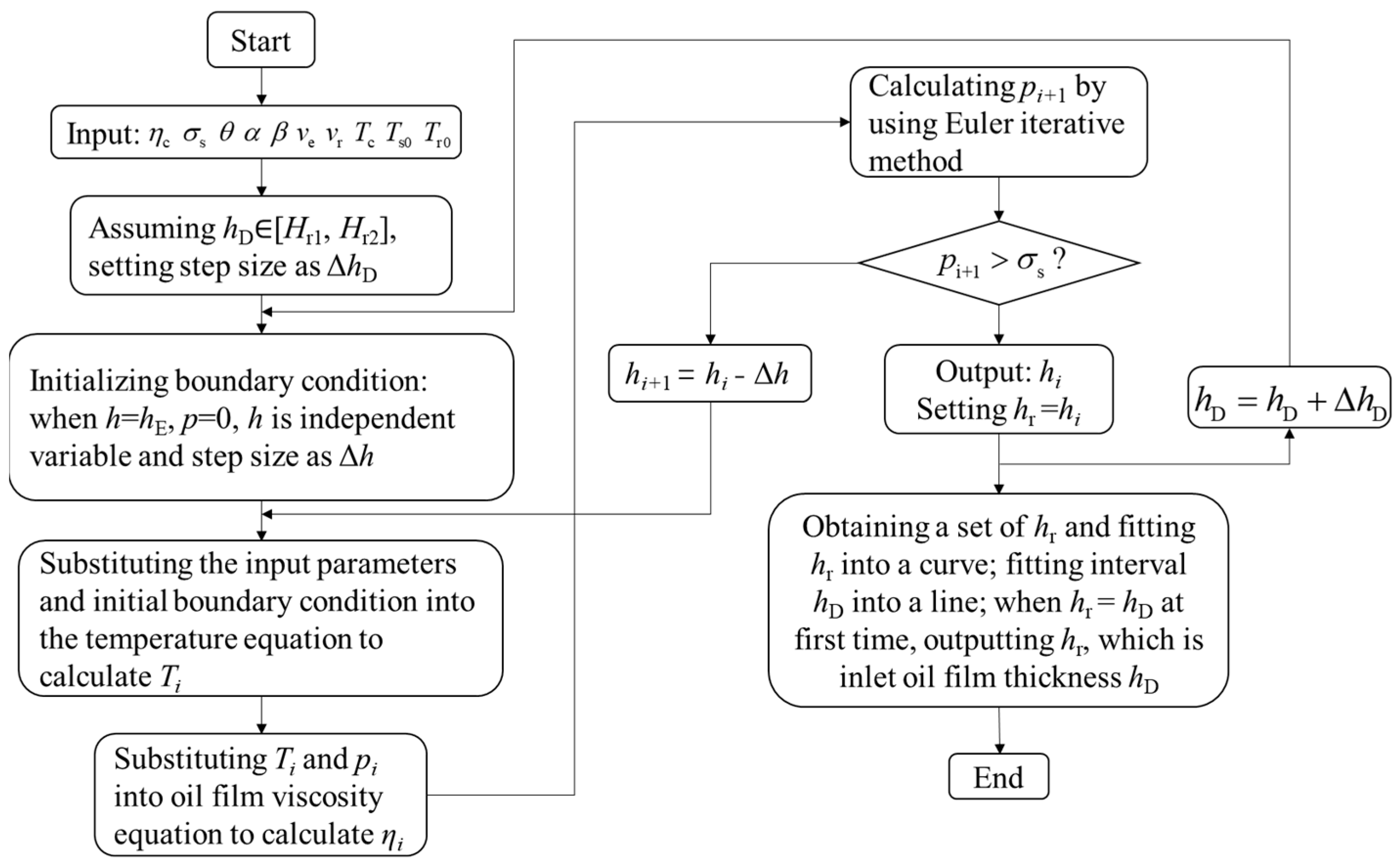
The flow chart is shown in Figure 3.
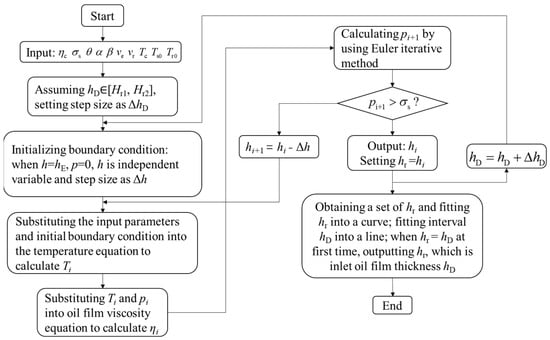
Figure 3.
Flow chart for calculating the inlet oil film thickness of the deformation zone, where and are iterative steps; and represent the given inlet oil film thickness range.
3.3. Calculation of Oil Film Thicknesses
- (1)
- Simulation parameters
The rolling process parameters, emulsion parameters, and regression parameters for the plate-out efficiency of oil film are listed in the following Table 2 and Table 3, respectively.
Table 2.
Rolling parameters.
Table 3.
Emulsion parameters.
Supposing the correction coefficients and as 1 under the provided lubrication conditions, and considering the influence of entry strip speed on plate-out time, it is characterized by
are regression coefficients from direct spray lubrication experiments, here taking . denotes the distance from the nozzles to the film formation position; here, .
The process parameters discussed in this study are derived from actual production processes, whereas the lubrication parameters are obtained through experimental research and analysis. In addition, under direct spray emulsion flow quantity at 30 L/min, the plate-out efficiency on strip is typically taken as 0.2689. For the recirculation emulsion flow quantity at 1200 L/min, and are set to be 0.0085 and 0.0080, respectively [10].
- (2)
- Estimation of oil film thickness
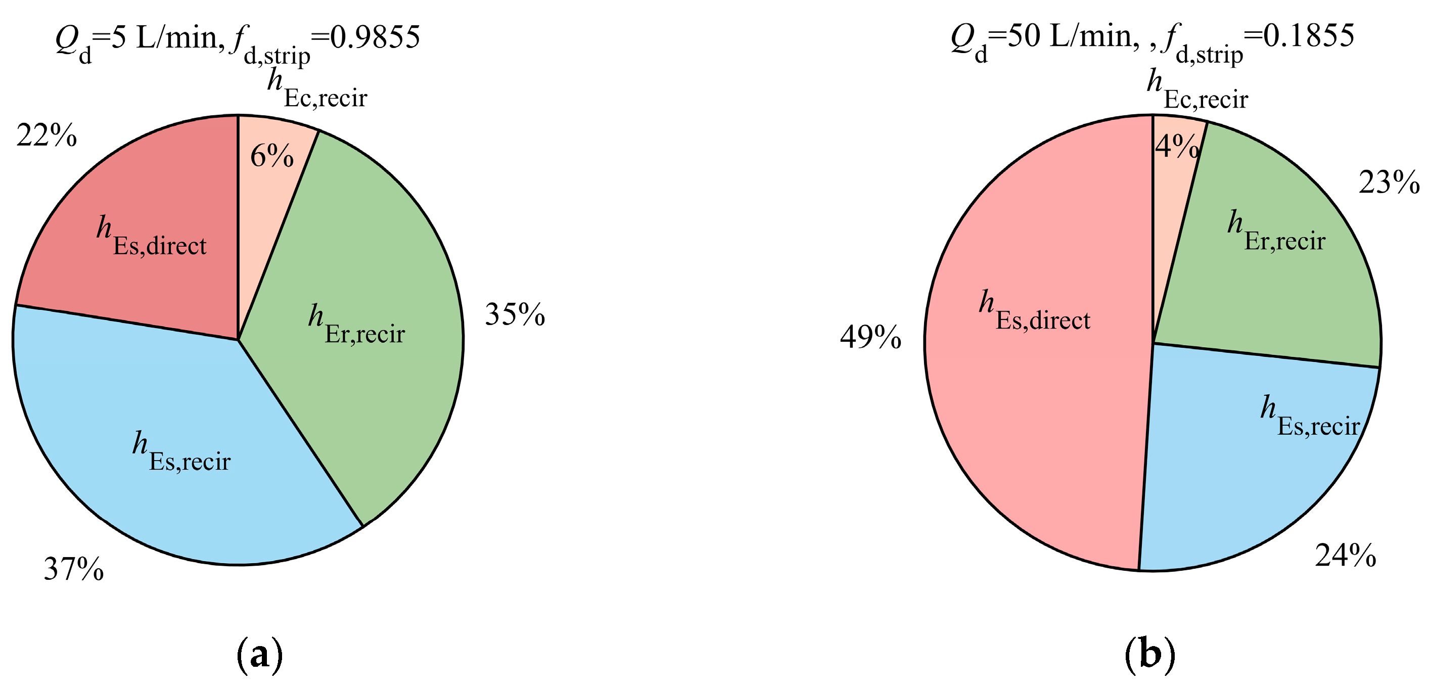
In order to compare the contribution of different lubrication subsystems to the initial oil film thickness under hybrid lubrication, the four parts in Equation (2) are separately calculated and shown in Figure 4, where the emulsion flow quantity of recirculation mode is fixed at 1200 L/min, and that of direct spray mode is individually set to be 5 L/min (left) and 50 L/min (right).
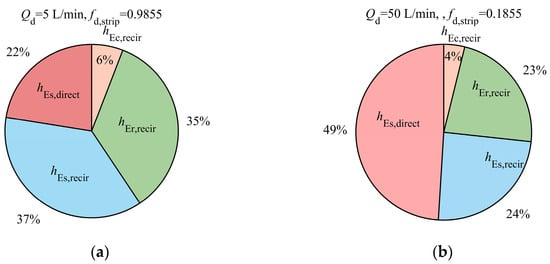
Figure 4.
Contribution of different components to . (a) distribution of oil film thickness at ; (b) distribution of oil film thickness at .
Applying the presented mathematical models of oil film thicknesses, under the provided rolling and lubrication conditions, the oil film thicknesses corresponding to the beginning and end positions of the wedge pre-deformation zone and the pressure distribution in the wedge are determined with the rolling speed varying, as shown in Figure 5.
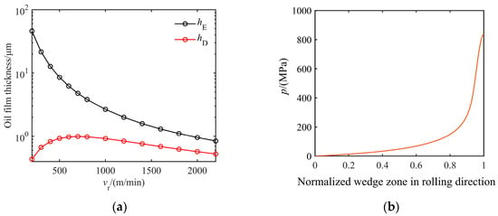
Figure 5.
Oil film thicknesses with the rolling speed varying and pressure distribution in the wedge: (a) oil film thicknesses with the rolling speed varying; (b) pressure distribution in the wedge at a speed of 1000 m/min.
In Figure 5, the oil film thickness curves show significant differences at low and high speeds. demonstrates an exponential decay trend with the rolling speed increasing; initially, is very small at low speed and ascends with the rolling speed gradually increasing, while subsequently it begins to decrease with ascending rolling speed.
- (3)
- Mechanism explanation
The variation phenomena of oil film thickness drawn in Figure 5 can be explained through the plate-out mechanism and the VPT effects involved in the formation and evolution process of oil film.
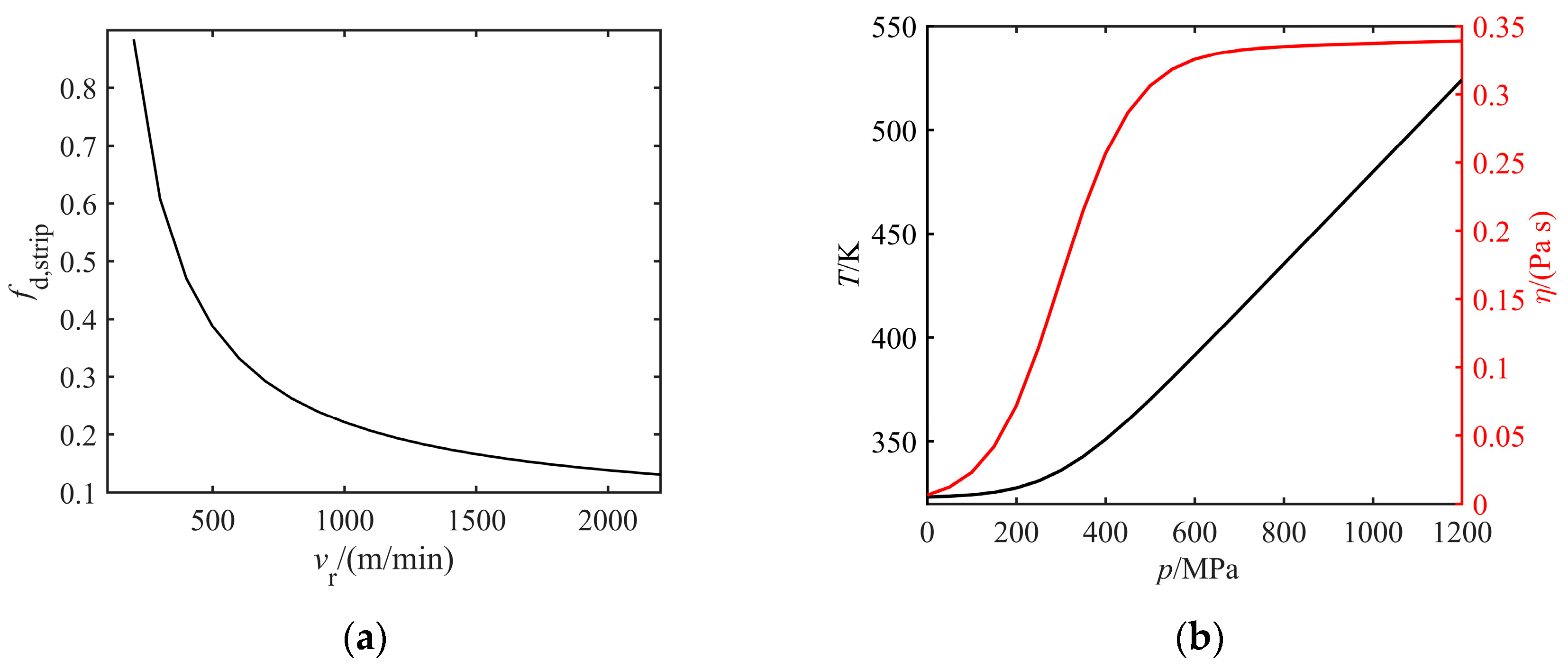
The recirculation nozzles directly spray emulsion into the rolling gap, which is less affected by the strip speed. According to Figure 4, the oil film thickness formed by direct spray lubrication makes a considerable contribution to the overall oil film thickness, and its plate-out efficiency on the strip varies with the rolling speed, as shown in Figure 6a. From the position of direct spray nozzles to the beginning of the pre-deformation zone, the oil droplets gradually plate-out on the strip surface and are attracted into the oil film. As the rolling speed increases, the plate-out time becomes shorter, the plate-out efficiency to form the oil film is lower, and the supply of emulsion also decreases accordingly. As a result, the oil film thickness gradually descends with increasing rolling speed.
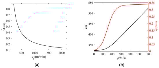
Figure 6.
Demonstration of mechanism explanation: (a) direct spray plate-out efficiency varying with rolling speed; (b) relationships among viscosity, pressure, and temperature.
At low speeds, the initial oil film is large and can be adequately supplied into the wedge zone to form the inlet oil film thickness , and so the oil film thickness gradually increases. However, the decrease in oil film thickness at high speeds can be considered as a comprehensive effect of two aspects: on the one hand, decreases and the supply is not rich; on the other hand, the VPT effects shown in Figure 6b become more significant because the temperature rise is much higher as the rolling speed increases, and it leads to an evident decrease in viscosity. Therefore, the oil film thickness shows a trend of increasing first and subsequently decreasing with the increasing rolling speed.
4. Influencing Factors of Inlet Oil Film Thickness
According to the established mathematical model, the oil film thickness is affected by various rolling process and lubrication parameters. The influence laws of these factors on the oil film thickness are analyzed in this section, which will be helpful for presenting effective regulation strategies.
4.1. Reduction Ratio and Rolling Speed
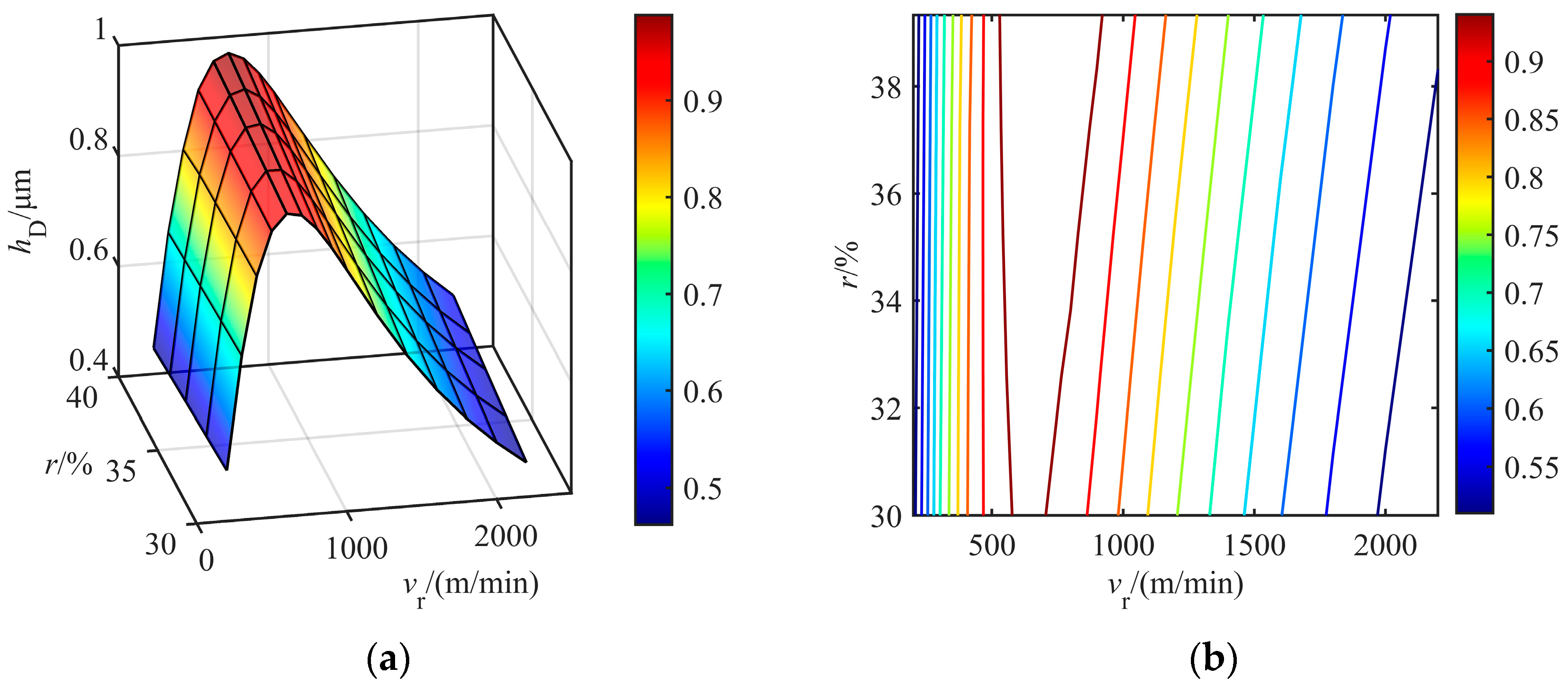
In the actual rolling process, the rolling speed threshold of chatter instability is closely related to the strip specification. Thus, the relationship between the reduction ratio (fixed exit thickness and varying entry thickness) and rolling speed is explored through the oil film thickness, as shown in Figure 7.
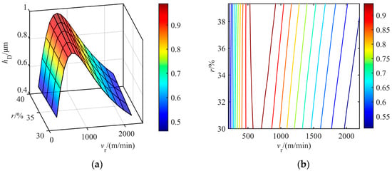
Figure 7.
Variation of oil film thickness with reduction ratio and rolling speed. (a) variation of with respect to and ; (b) contour diagram of with respect to and .
According to Figure 7, it can first be illustrated that the inlet oil film thickness decreases at a high rolling speed. Further discussion is provided as follows:
- (1)
- Lower speed (500 m/min): According to the metal flow equation, under fixed exit thickness and increased entry thickness, the entry speed descends, resulting in a higher initial oil film thickness . However, the oil film entrapment ability through the wedge pre-deformation zone is relatively poor due to the low rolling speed, so that the oil film thickness decreases with the increase in reduction ratio.
- (2)
- Higher speed (>500 m/min): Under the same rolling conditions, high rolling speed balances the improvement of entrapment ability and the reduction in initial oil film thickness, and with the speed sum decreasing, the temperature rise effect is weakened. So, the oil film thickness tends to become larger with the increase in reduction ratio.
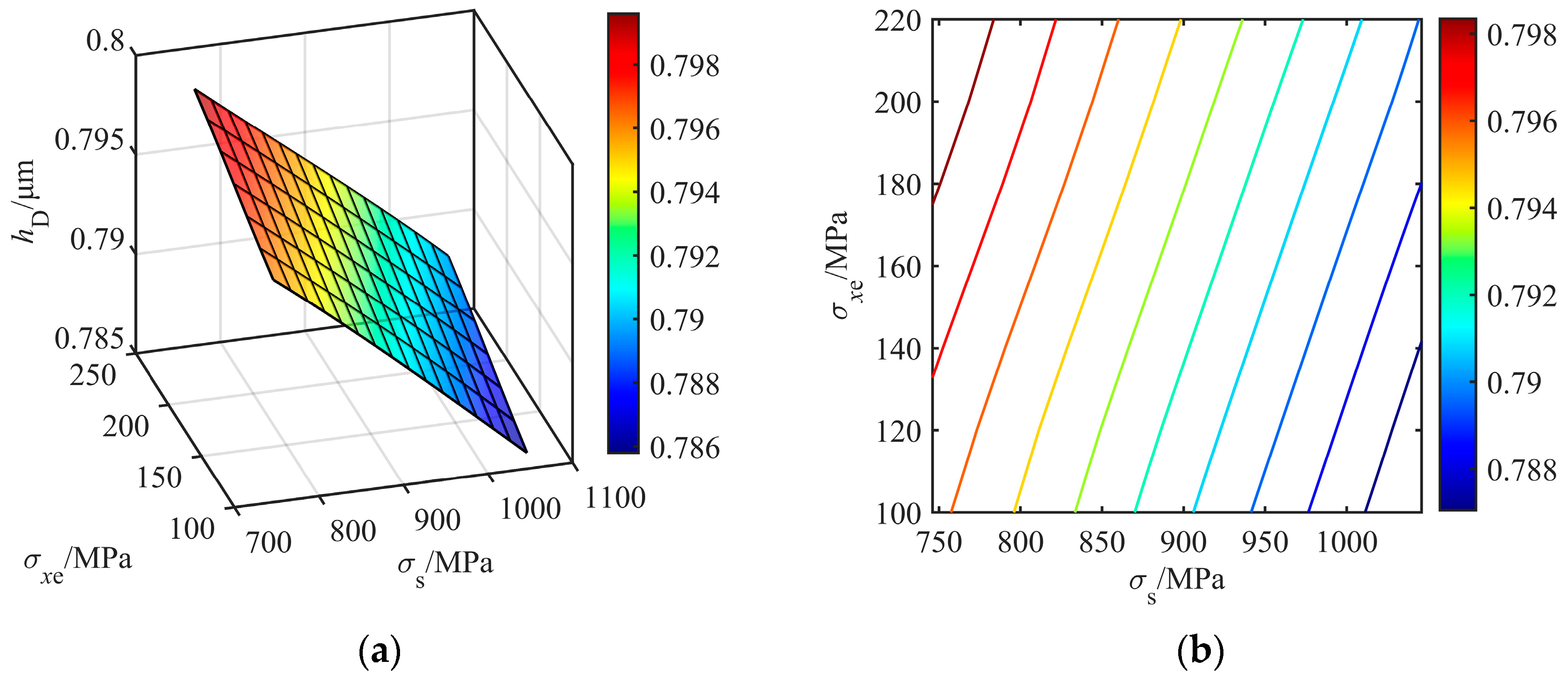
4.2. Entry Tension Stress and Strip Deformation Resistance
Figure 8 shows the influence of entry tension stress and strip deformation resistance on the oil film thickness. The variation curves can be described by an approximately linear function as follows:
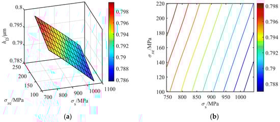
Figure 8.
Variation in oil film thickness with entry tension stress and strip deformation resistance. (a) variation of with respect to and ; (b) contour diagram of with respect to and .
It can be found that is negatively correlated with the deformation resistance and has positive correlation to the entry tension. Thus, for the downstream stands in the cold tandem rolling mill of high-strength steel sheets, the deformation resistance becomes higher due to the work-hardening behavior, the oil film thickness becomes thinner, and the rolling process is more prone to instability.
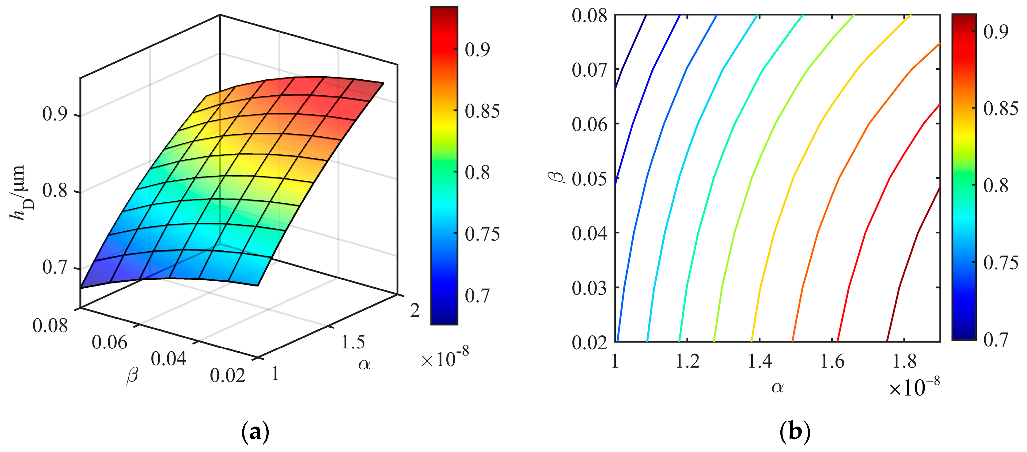
4.3. Viscosity-Pressure and Viscosity-Temperature Coefficients
With the VPT effects taken into consideration in the presented model, it is necessary to discuss the influence of viscosity–pressure and viscosity–temperature coefficients on the oil film thickness, as shown in Figure 9.

Figure 9.
Variation in oil film thickness with VPT coefficients and . (a) variation of with respect to and ; (b) contour diagram of with respect to and .
The relationship of the oil film thickness and VPT coefficients is quantitatively regressed as a quadratic function, i.e.,
If a larger oil film thickness is expected, a kind of lubricant oil with a higher viscosity–pressure coefficient and lower viscosity–temperature coefficient should be picked or developed.
4.4. Emulsion Flow Quantities of Direct Spray and Recirculation Lubrication Subsystems
In a hybrid lubrication system, the emulsion flow quantities under different lubrication subsystems are the most important and easily controllable parameters. Figure 10 shows the influence of emulsion flow quantities from direct spray and recirculation lubrication nozzles on the oil film thickness.
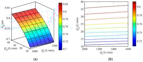
Figure 10.
Variation in oil film thickness with emulsion flow quantities and . (a) variation of with respect to and ; (b) contour diagram of with respect to and .
To fit the relationship in Figure 10, the expression is presented as
According to the calculation results, the following conclusions can be drawn:
- (1)
- When the flow quantity of recirculation lubrication reaches a certain level, an impact on the outflow of the formed oil film on the plate may occur, so that the increase in flow quantity cannot cause a significant increase in oil film thickness.
- (2)
- The oil film thickness can become significantly large by increasing he flow quantity of direct spray lubrication. Therefore, in the hybrid lubrication, the effective regulation of oil film thickness is generally achieved by changing the direct spray emulsion flow quantity.
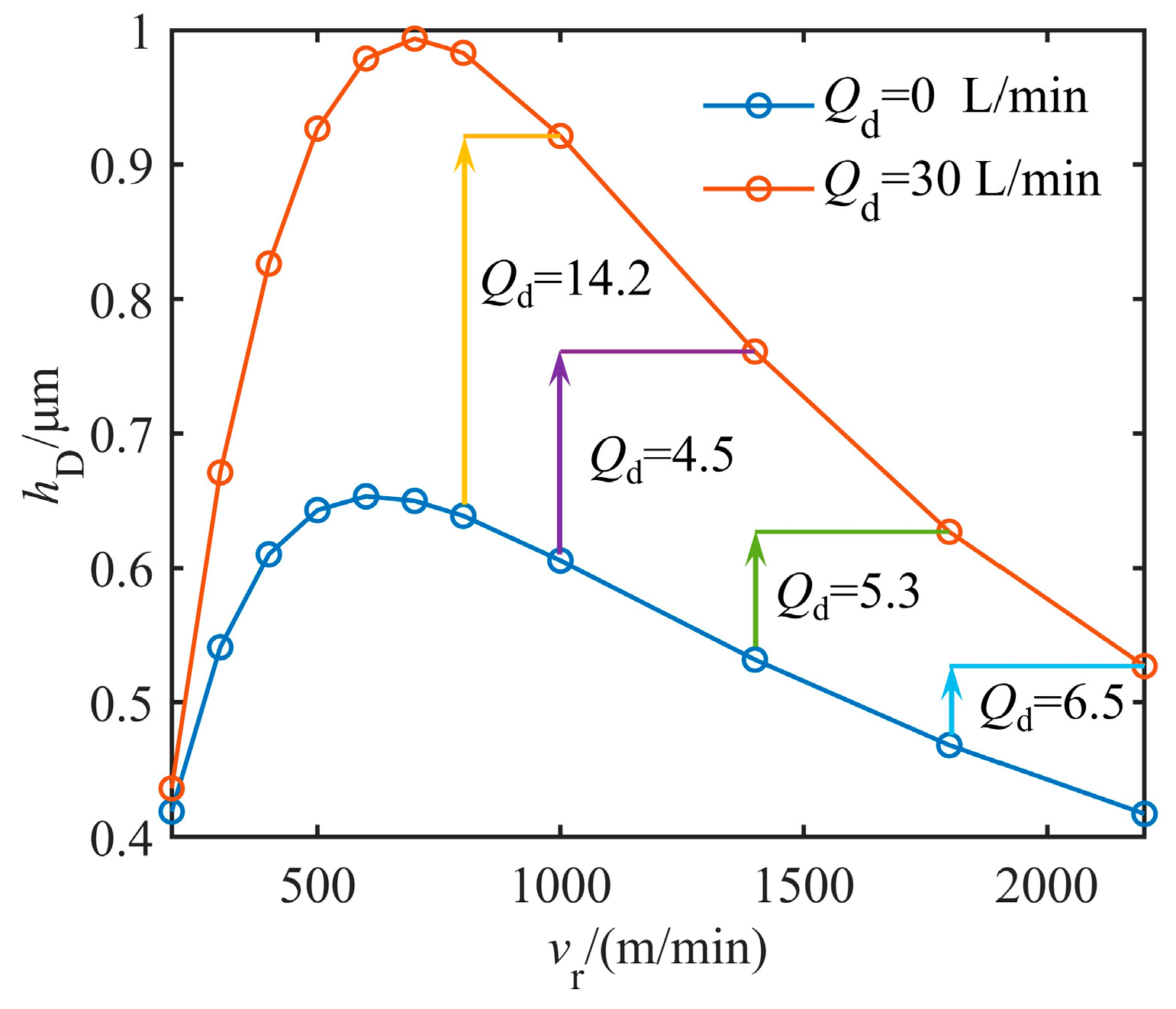
5. Dynamic Regulation Approach of Oil Film Thickness
Figure 11 presents the direct emulsion flow quantity under the hybrid lubrication required to regulate the inlet oil film thickness. At high speeds, the oil film thickness decreases as the rolling speed increases. Therefore, when the oil film thickness is adjusted to the same level within a specific rolling speed, higher speeds require more flow quantity. When the oil film thickness is adjusted to 0.761 μm during , the required emulsion flow quantity is 4.5 L/min at , and 30 L/min at .
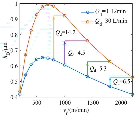
Figure 11.
Regulation of inlet oil film thickness.
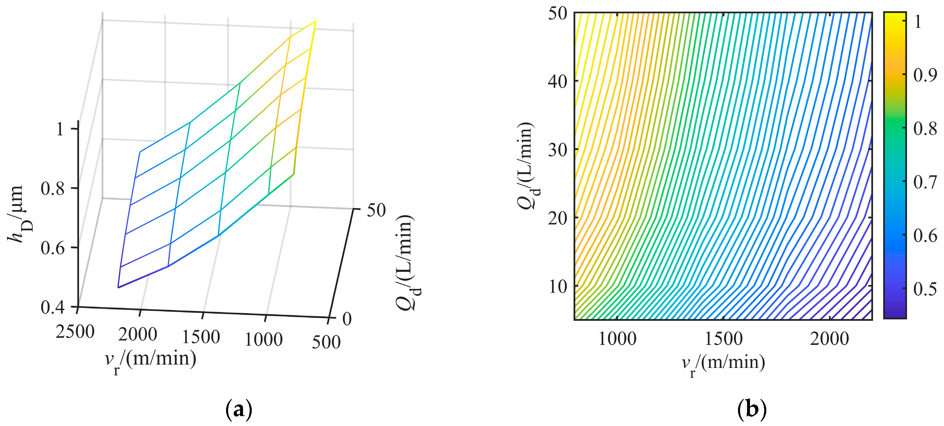
The relationship of the oil film thickness with respect to rolling speed and direct emulsion flow quantity is depicted in Figure 12.
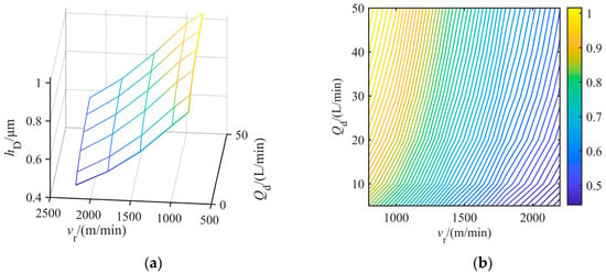
Figure 12.
Variation in inlet oil film thickness with rolling speed and emulsion flow quantity. (a) variation of with respect to and ; (b) contour diagram of with respect to and .
Based on the curves in Figure 12, the oil film thickness exhibits an approximately linear relationship with rolling speed and a quasi-quadratic relationship with the direct emulsion flow quantity. The functional relationship among , , and can be provided as
According to Equation (29), the emulsion flow quantity of direct spray lubrication can be dynamically regulated with the actual rolling speed and the expected oil film thickness, so that stable high-speed rolling can be achieved.
6. Conclusions
This study proposes a novel framework for modeling oil film thickness in high-speed cold rolling of high-strength thin sheets, explicitly addressing the viscosity–pressure–temperature (VPT) coupling effects under hybrid lubrication. The principal findings and contributions are as follows:
- (1)
- The initial oil film thickness in the pre-deformation zone was established based on plate-out and dynamic concentration formation mechanisms under the hybrid lubrication. Increasing the direct spray flow quantity from 5 L/min to 50 L/min, the plate-out efficiency on the strip surface is nearly tripled. A novel inlet oil film thickness model was developed by integrating the Reynolds equation, the VPT effects, the energy equation, and the continuity equation. Moreover, the nonlinear relationship between inlet oil film thickness and rolling speed was obtained and mechanistically explained.
- (2)
- Quantitative analysis of oil film thickness was conducted with respect to paired parameters, including reduction rate and rolling speed, entry tension stress and strip deformation resistance, and viscosity–pressure and viscosity–temperature coefficients, as well as emulsion flow quantities of direct spray and recirculation lubrication subsystems. The results provide theoretical foundations for chatter instability under high-speed rolling, lubricant selection, and regulating oil film thickness through emulsion flow quantity.
- (3)
- A quantitative relationship between oil film thickness, rolling speed, and direct emulsion flow quantity was established. When the oil film thickness is adjusted to 0.761 μm at 1400 m/min, the required emulsion flow quantity is 30 L/min. The derived equation enables real-time lubrication control, resolving the speed–lubrication relationship in high-speed cold rolling of high-strength thin sheets.
- (4)
- Based on the significant advantages of mixed lubrication systems, the proposed model is suitable for high-speed cold rolling of high-strength thin sheets, enabling stable rolling at speeds exceeding 20 m/s, producing sheets with thicknesses of ≤0.3 mm and strengths up to 1000 MPa.
- (5)
- This novel model has not yet been directly validated through actual rolling mill experiments due to constraints in rolling conditions. However, this will be indirectly verified by collecting specific data from the rolling process, thereby enhancing its applicability.
Author Contributions
Conceptualization, Y.L. and X.Y.; methodology, Y.L. and X.Y.; software, L.L. and Y.X.; validation, Y.L., X.Y. and L.L.; formal analysis, Y.X.; investigation, Z.G.; resources, X.Z.; data curation, X.Z.; writing—original draft preparation, Y.L.; writing—review and editing, Z.G.; visualization, Y.X.; supervision, X.Y. and X.Z.; project administration, X.Y.; funding acquisition, Z.G. All authors have read and agreed to the published version of the manuscript.
Funding
This research was funded by the National Natural Science Foundation, China (No. 51775038).
Data Availability Statement
The data presented in this study are available on request from the corresponding author. The data are not publicly available due to privacy restrictions.
Conflicts of Interest
Authors Yujin Liu, Xuechang You and Lei Liu were employed by the company Shougang Zhixin Electromagnetic Materials (Qian’an) Co., Ltd. The remaining authors declare that the research was conducted in the absence of any commercial or financial relationships that could be construed as a potential conflict of interest.
Appendix A
References
- Lee, Y.; Kim, H.; Lee, J. Work hardening behavior in multi-pass rolling of advanced high-strength steel. J. Mater. Process. Technol. 2018, 252, 254–263. [Google Scholar] [CrossRef]
- Zhang, Q.; Wang, L.; Tieu, A.K. Friction-induced rolling force prediction in tandem cold rolling of ultra-high strength steel. Tribol. Int. 2020, 144, 106121. [Google Scholar] [CrossRef]
- Wang, C.; Sun, J.; Liu, X. Dynamic instability analysis of tandem rolling mills under high friction conditions. Mech. Syst. Signal Process. 2019, 128, 352–366. [Google Scholar] [CrossRef]
- Wei, L.Q.; Zhai, Z.H. Influence of rolling lubrication on self-excited vibration in 1420 continuous cold rolling mill. J. Iron Steel 2006, 18, 28–31. [Google Scholar] [CrossRef]
- Reich, R.; Urbanski, J. Experimental support for the dynamic concentration theory of forming an oil reservoir at the inlet of the roll bite by measuring the onset speed of starvation as a function of oil concentration and droplet size. Tribol. Trans. 2004, 47, 489–499. [Google Scholar] [CrossRef]
- Lo, S.W.; Yang, T.C.; Cian, Y.A. A model for lubrication by oil-in water emulsions. J. Tribol.-Trans. ASME 2010, 132, 011801. [Google Scholar]
- Azushima, A.; Inagaki, S.; Ohta, H. Plating out oil film thickness on roll and workpiece during cold rolling with O/W emulsion. Tribol. Trans. 2011, 54, 275–281. [Google Scholar] [CrossRef]
- Fujita, N.; Kimura, Y. Plat-out efficiency related to oil-in-water emulsions supply conditions on cold rolling strip. Proc. Inst. Mech. Eng. Part J J. Eng. Tribol. 2013, 227, 413–422. [Google Scholar]
- Wilson, W.R.D.; Walowit, J.A. An isothermal hydro dynamic lubrication theory for strip rolling with front and back tension. In Tribology Convention 1971; Institution of Mechanical Engineers: London, UK, 1971; pp. 164–172. [Google Scholar]
- Fujita, N.; Kimura, Y.; Kobayashi, K. Estimation model of plate-out oil film in high-speed tandem cold rolling. J. Mater. Process. Technol. 2015, 219, 295–302. [Google Scholar] [CrossRef]
- Bian, X.X.; Wang, Q. A comprehensive mathematical model for an accurate calculation of the oil film thickness of strip cold rolling. Proc. Inst. Mech. Eng. Part J J. Eng. Tribol. 2020, 234, 350–361. [Google Scholar] [CrossRef]
- Cheng, L.; Kiet, T. Modeling of the inlet zone in the mixed lubrication situation of cold strip rolling. J. Mater. Process. Technol. 2003, 140, 569–575. [Google Scholar] [CrossRef]
- Xin, Y.L.; Gao, Z.Y. Influence of friction-lubrication characteristics varying with rolling speed on instability of chatter and slip in cold tandem rolling process. J. Iron Steel Res. Int. 2024, 31, 894–908. [Google Scholar] [CrossRef]
- Muramoto, H. 338 Curtailment of the unit consumption of the rolling oil with hybrid system. J. Iron Steel Inst. Jpn. 1982, 68, 948–951. [Google Scholar]
- Yukio, K.; Noriki, F.; Yukihiro, M. High-speed rolling by hybrid-lubrication system in tandem cold rolling mills. J. Mater. Process. Technol. 2015, 216, 357–368. [Google Scholar] [CrossRef]
- Li, Z.H.; Han, P. Research and Application of the Mathematical Model of Emulsified Fluid Flow in Silicon Steel Rolling Process. Shanxi Metall. 2012, 52, 850–857. [Google Scholar] [CrossRef]
- Cui, Y.Y.; Bai, Z.H. Oil film thickness model in deformation zones during double cold reduction rolling. China Mech. Eng. 2019, 30, 560–567. [Google Scholar]
- Fujita, N.; Kimura, Y.; Kobayashi, K. Dynamic control of lubrication characteristics in high speed tandem cold rolling. J. Mater. Process. Technol. 2016, 229, 407–416. [Google Scholar] [CrossRef]
- Li, X.T.; Sun, Y.X. Optimal setting technology of process lubrication system for 3+1 emulsion system. Iron Steel 2022, 57, 110–118. [Google Scholar] [CrossRef]
- Yukio, K.; Noriki, F.; Yukihiro, M. Hybrid lubrication for high-speed rolling. J. Mater. Process. Technol. 2015, 216, 357–368. [Google Scholar]
- Bai, Z.H.; Wang, N. Optimization of lubrication system for flatness control process in cold tandem rolling. Iron Steel 2021, 56, 96–102. [Google Scholar] [CrossRef]
- Hanafi, L.; Mufid, M.S. Analytical solution approximation for bearing. AIP Conf. Proc. 2017, 1867, 020041. [Google Scholar] [CrossRef]


Disclaimer/Publisher’s Note: The statements, opinions and data contained in all publications are solely those of the individual author(s) and contributor(s) and not of MDPI and/or the editor(s). MDPI and/or the editor(s) disclaim responsibility for any injury to people or property resulting from any ideas, methods, instructions or products referred to in the content. |
© 2025 by the authors. Licensee MDPI, Basel, Switzerland. This article is an open access article distributed under the terms and conditions of the Creative Commons Attribution (CC BY) license (https://creativecommons.org/licenses/by/4.0/).