Abstract
Revolute and prismatic pair clearances are common in various mechanisms, and their motion state seriously affects the accuracy of the mechanism. Adding lubricant to a kinematic pair can effectively counteract the adverse influence of a collision force. Thus, this work introduces an advanced modeling method that considers the combined effects of a lubricated revolute and prismatic clearance, as well as component flexibility, and studies the influence of their coupling effect on the dynamic response and nonlinear characteristic of mechanisms. The specific content of this paper is as follows: Firstly, revolute lubrication clearance and prismatic pair clearance models are established. Secondly, rigid components and flexible components are described based on the reference point coordinate method and absolute nodal coordinate formulation. Then, based on the Lagrange multiplier method, a rigid–flexible coupling dynamics model with revolute lubrication clearance and prismatic clearance is established. Finally, the dynamic responses of the mechanism are analyzed, including the displacement, velocity, and acceleration of the slider, the driving torque of the crank, and the center trajectories of the revolute clearance and prismatic clearance. Qualitative research is conducted on the nonlinear characteristics of the system through a phase diagram and Poincaré map. This quantitative study is conducted on the nonlinear characteristics of a system using the maximum Lyapunov exponent. The influences of different parameters on the dynamic response and nonlinear characteristic of the mechanism are analyzed. The results indicate that lubrication effectively reduces the influence of the clearance on the dynamic response and nonlinear characteristic of the mechanism, resulting in a decrease in the peak dynamic response and a weakening of the chaotic phenomenon. Further, as the driving speed increases, the dynamic viscosity decreases the clearance value increases, and the stability of the mechanism decreases.
1. Introduction
In mechanical systems, clearances often occur due to material deformation, manufacturing errors, and frictional wear [1,2,3,4,5,6,7,8,9]. The collision force caused by clearance accelerates the wear of corresponding components and exacerbates system vibration. In addition, modern mechanical equipment is being developed to operate at higher speeds and higher precision. Factors such as the joint clearance, component flexibility, and lubrication effectiveness significantly affect the dynamic performance of precision engineering mechanisms. Therefore, idealized dynamic models cannot accurately reflect the actual dynamic characteristics of mechanical systems [10,11,12,13,14,15,16,17]. In order to accurately predict dynamic behavior, it is necessary to consider as many influencing factors as possible in dynamic modeling, such as the component flexibility, clearance, and lubrication.
Researchers have conducted extensive investigations on the impact of dry friction clearance at revolute pairs on the dynamic characteristics of mechanical systems [3,18]. For instance, Xiang et al. [19] studied the influence of dry friction clearance and parameter uncertainty on the dynamic performance of space robot manipulators. It was found that the coupling effect of clearance and an uncertain parameter has a significant impact on the displacement, velocity, and sensitivity of a mechanism. Bai et al. [20] introduced an accurate method for modeling rotating pairs that considered both axial and radial clearances simultaneously, and it was found that a larger clearance value will lead to a larger peak in the motion characteristics, driving the torque of the crank and the collision force of the mechanism, resulting in poorer stability of the mechanism. Li et al. [21] investigated the dynamic responses and chaotic behavior of a planar deployable shear structure with dry friction clearance. A control scheme was proposed to enhance its stability. Chen et al. [22] proposed an experimental and analytical method to study the performance of high-precision mechanical mechanisms with dry friction revolute clearance, and conducted dynamic performance testing, stability analysis, and energy analysis on a mechanism under different working conditions. Chen et al. [23] analyzed the effects of the position, quantity, and size of dry friction clearance on the dynamic response of rigid mechanisms, and revealed the chaotic phenomenon in the mechanism that they studied through Poincaré diagrams and phase diagrams. The clearance effect was found to reduce the performance of the mechanism, leading to the occurrence of chaotic phenomena in the mechanism.
The attention of numerous scholars has been drawn to the concept of prismatic clearance [24]. Wu et al. [25] formulated a theoretical model and explored the impact of dry friction prismatic clearance on the dynamics of a mechanism. It was found that the larger the clearance value, the faster the driving speed, leading to a larger peak in the dynamic response of the studied mechanism and a more pronounced chaotic characteristic of the mechanism. Flores et al. [26] used the Lagrange equation to establish the dynamic equation of a crank slider mechanism with prismatic clearance, revealed the motion trajectory of the slider, and analyzed the influence of prismatic clearance on the motion characteristics of the mechanism. In addition, Qian et al. [27] introduced an innovative contact detection method that can distinguish the positional relationship between a slider and guide rail based on the vector relationship between the guide rail vertices and slider vertices.
In pursuit of more accurate dynamic analyses, researchers have explored the effects of the combined influence of dry revolute clearance and the flexibility of various elements upon the dynamic behavior of mechanisms [28]. By employing the Hamiltonian method, Chen et al. [29] investigated the dynamic characteristics of a plane rotating beam with dry friction clearance, taking into consideration the revolute clearance and elastic deformation. The coupling effect between the clearance of the motion pair and the elasticity of the component led to an increase in the vibration frequency of the component. Sun et al. [30] developed a simplified dynamic model for a flexible manipulator, accounting for random material properties and revolute joint clearance. The numerical simulation results showed that the clearance, component flexibility, and uncertainty all had a significant impact on the motion accuracy and dynamic behavior of the robotic arm. Wan et al. [31] took into account various factors that impact dynamics, including the rotor imbalance, structural flexibility, and clearance. A precise dynamic equation for the momentum wheel assembly of a satellite antenna was formulated. The research results indicated that, the larger the clearance, the more significant the fluctuation amplitude of the response, and that increasing the driving velocity will lead to high-frequency and large-amplitude oscillations in the system. Chen et al. [32] proposed a modeling method to study the dynamic characteristics of a hydraulically driven shell manipulator with dry friction rotating clearance. The influences of the clearance size and stiffness on the mechanism’s dynamics were analyzed, including its motion characteristics and the collision forces.
The wear and friction of the motion pair have a significant impact on the accuracy and stability of mechanical systems [33], which has aroused great interest among many researchers. Xu et al. [34] proposed a modeling method for rotating joints with continuously reconstructed wear profiles in multi-body systems. It was found that the degree of wear of a joint was related to the dynamic characteristics of the mechanism, which in turn affected the dynamic performance of the mechanism. Li et al. [35] proposed a contact model for revolute clearance based on fractal theory to achieve the more accurate calculation of contact stiffness and radial contact force. The research results indicated that the improved contact model is more suitable for gaps of different sizes than traditional models and can more accurately describe the changes in contact force. Taking a solar cell array system as a case study, Li et al. [36] formulated a differential equation to describe the dynamics of the rigid–flexible coupling system. It was focused on investigating the mechanical response and wear characteristic of a mechanism system, considering factors such as the clearance joints and solid cladding.
The lubricating oil generates an oil film force that separates the shaft from the bearing, thus avoiding contact collisions at the clearance hinges. This separation effectively reduces the vibration, friction, and wear caused by contact forces at the clearance hinges. Many scholars have conducted extensive studies on the dynamics of mechanisms that consider lubrication clearance [37,38,39]. Tian et al. [40] focused on the effect of lubrication clearance in ball joints. They employed the Reynolds equation to compute the lubrication force and proposed an analytical and computational approach for assessing the dynamics of a spatial flexible crank-slider mechanism as well as the single pendulum mechanism. Tao et al. [41] introduced a solution method for determining the dynamics of a plane rigid crank slider mechanism that contained a rotating lubrication clearance. Flores et al. [42] conducted the dynamics modeling and simulation of a rigid four-bar mechanism that contained lubricated ball joints. Tian et al. [43] proposed a new flexible multi-body dynamic model that includes lubrication clearance. The influences of different lubrication clearance values on the displacement, velocity, and acceleration of a slider were analyzed. Chen et al. [44] established a dynamics model of a rigid body mechanism with multiple lubrication clearances. It was found that lubrication effectively reduced the peak of the dynamic response and slowed down the vibration frequency of the mechanism. Taking into account the lubrication revolute clearance and flexibility, Chen et al. [45] comprehensively built a dynamics model of a six-link mechanism containing lubrication clearances, and analyzed the influence of the lubrication clearance of the revolute pair on the dynamic response, phase diagram, Poincaré map, etc.
The main contribution of this paper is to establish an accurate dynamic model of a multi-link mechanism (MLM) by comprehensively considering various interference factors such as the lubrication rotation clearance, prismatic clearance, and component flexibility, which provides a theoretical basis for predicting the dynamic response of an actual multi-link system. Based on a phase diagram, Poincaré map, and maximum Lyapunov exponent, the nonlinear dynamic characteristics of the multi-link system are analyzed through a combination of qualitative and quantitative methods, which also provides clues for the in-depth study of the nonlinear dynamic behavior of multi-link systems.
The main arrangement of this paper is as follows: Section 1 is the introduction section. In Section 2, the clearance models of the lubricated revolute pair and the prismatic pair are established, the flexible beam element model is established, and the rigid–flexible coupling (RFC) dynamic model of a multi-link mechanism with lubricated revolute clearance and prismatic clearance is derived. In Section 3, the effects of lubrication and dry friction revolute clearance on the dynamic response and nonlinear characteristics of a rigid–flexible coupled multi-link mechanism are compared and analyzed, and the effects of different driving speeds, dynamic viscosities, and clearance values on the dynamic response and nonlinear characteristics of the mechanism are also analyzed. In Section 4, the conclusions of this paper are presented.
2. Dynamics Model of RFC-MLM with Revolute Lubrication Clearance and Prismatic Clearance
The main intent of this section is to establish a clearance model for a prismatic pair, a lubrication clearance model for a revolute pair, and a flexible beam element model.
2.1. Prismatic Pair Clearance Model
A clearance model for the prismatic pair is established in this section.
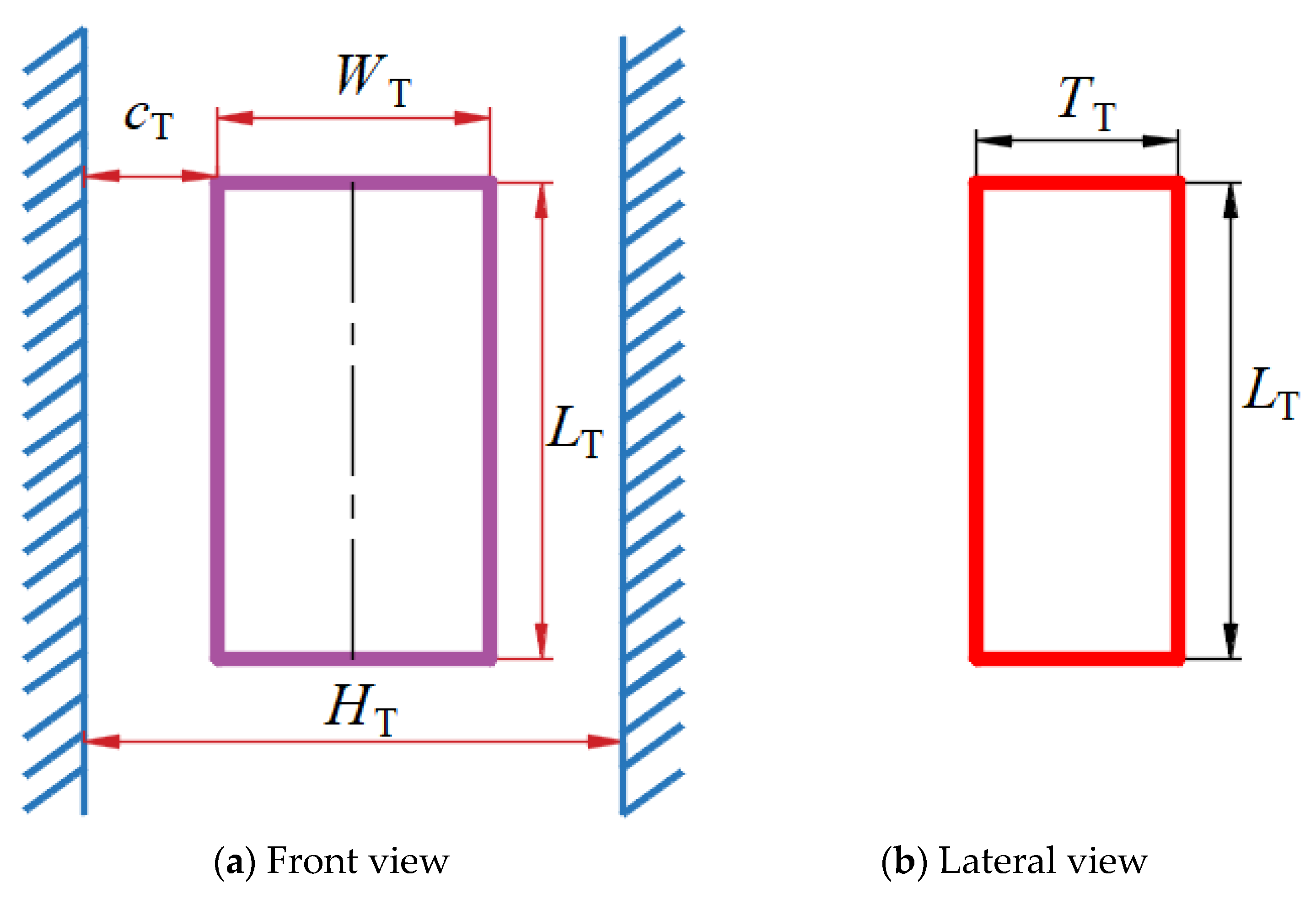
Figure 1 illustrates the model for prismatic pair clearance. The size of the clearance in a prismatic pair is denoted by , for which the expression is given as follows:

Figure 1.
Clearance model of prismatic clearance.
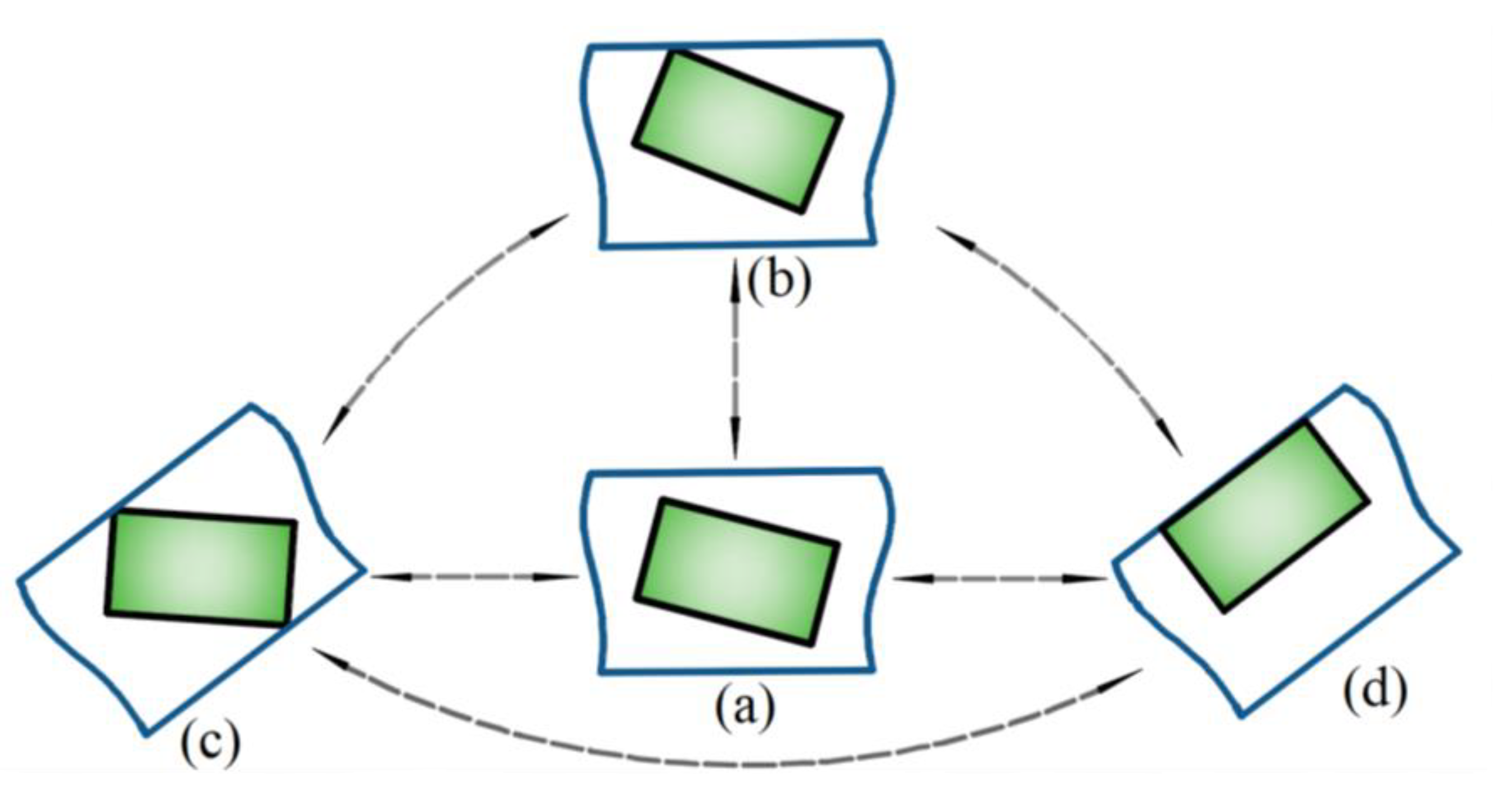
The motion of prismatic clearance can be mainly divided into four situations, as shown in Figure 2.

Figure 2.
Position relationship of prismatic clearance pair.
- As shown in Figure 2a, the slider is in a free state without any collision phenomenon;
- As shown in Figure 2b, a corner of the slider collides with the guide rail surface;
- As shown in Figure 2c, the diagonal of the slider collides with the guide rail surface;
- As shown in Figure 2d, the same side of the slider collides with the guide rail surface.
In Figure 3, the analytical model for prismatic pair clearance is depicted. Point A is selected as a representative example. The position vectors for point A on slider m and guide rail n are denoted as:
where and are the position vector of the centroid of the slider and guide rail in the global coordinate system, respectively; and are the transformation matrix of the slider and guide rail, respectively; and are the position vector of any point A of the slider and guide rail in the local coordinate system, respectively.
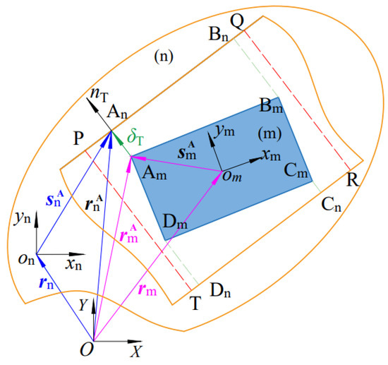
Figure 3.
The analytical model of prismatic pair clearance.
The position vector between Am and An is:
In instances where a collision occurs between the slider and the guideway, and are collinear and in the opposite direction. This condition is expressed as [3]:
where is the normal vector.
The penetration at the translatioanl clearance is as follows:
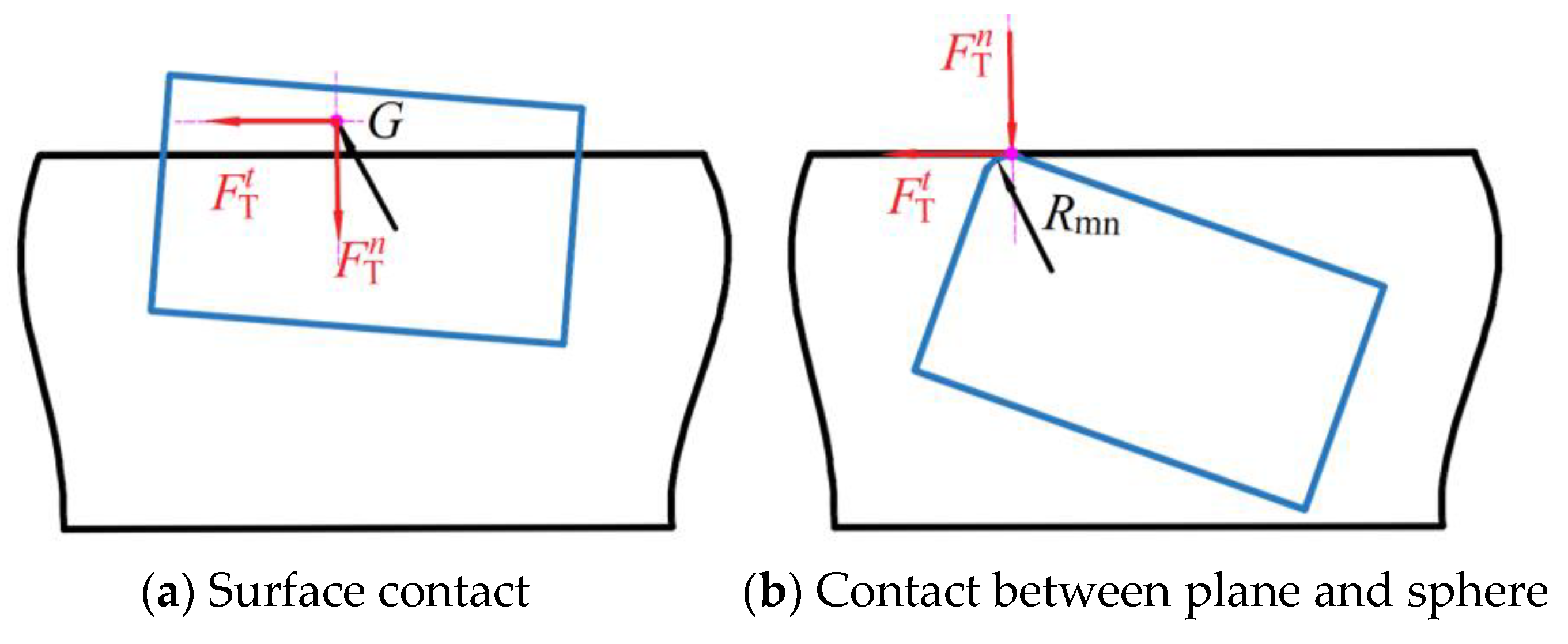
The contact force between the slider and the guide rail is generated when two adjacent corners of the slider come into contact with the guideway. This contact force acts on the centroid of the penetration area, as illustrated in Figure 4a. The collision force can be expressed as follows [3,46]:
where and , as shown in Figure 1. and , Em and En are the elastic modulus, and and are Poisson’s ratio.
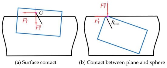
Figure 4.
Contact mode between slider and guide rail.
Figure 4b illustrates the scenario in which one or two diametrically opposed corners of the slider make contact with the guideway. Under such circumstances, it is reasonable to approximate the interaction as a collision between a sphere and a plane. According to reference [47], the force resulting from this collision can be characterized as follows:
where is the stiffness coefficient at the clearance of the prismatic pair, , and Rmn represents the radius of the curvature of the slider corner.
The damping coefficient can be written as follows:
A modified version of the Coulomb friction model presented by Ambrosio is used [28,32,36].
where is the coefficient of friction and is coefficient of correction
where v0 and v1 are the limit value of a given speed.
2.2. Revolute Lubrication Clearance Model
This section establishes a lubrication clearance model for the revolute pair.
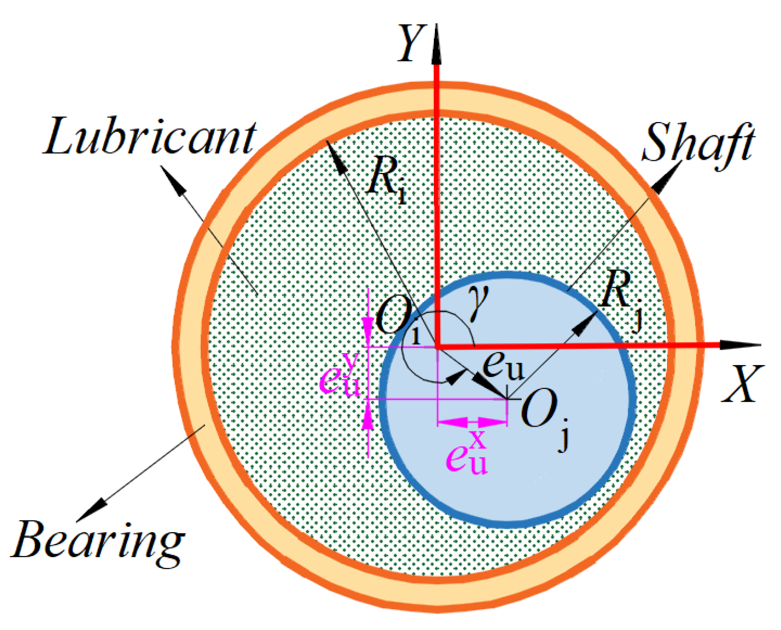
The revolute lubrication clearance model is shown in Figure 5. The eccentricity vector of the lubrication clearance can be expressed as follows:
where rio and rjo are position vectors of the centroid of the shaft and bearing, respectively.
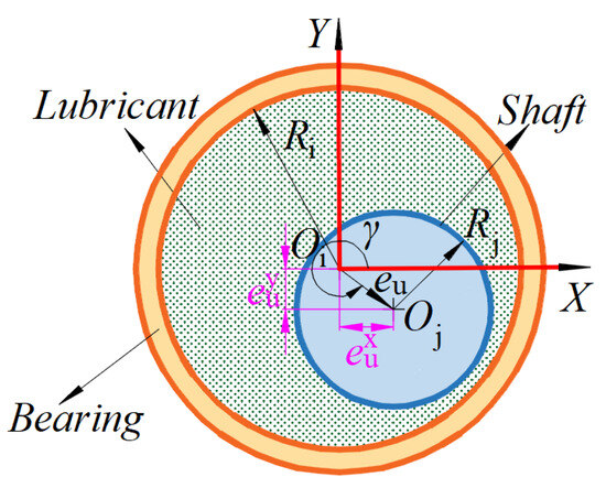
Figure 5.
Revolute lubrication clearance model.
The lubrication clearance’s eccentricity within a revolute pair is as follows:
where eu represents the magnitude of the eccentricity vector of the lubrication clearance of the revolute joint, , and cu is the value of the revolute lubrication clearance, cu = Ri − Rj.
The first derivative of the eccentricity ratio with respect to time denoted is as follows:
where is the first derivative of the eccentricity vector of the revolute lubrication clearance.
The angle included by the direction of the eccentric vector and the positive x-axis is known as the offset angle, which is denoted as follows:
where and are components of the eccentricity vector of the lubrication clearance in the X and Y directions, respectively.
The offset angular velocity is obtained by taking the first-order derivative of Equation (14) [39].
where and are the first derivatives of the eccentricity components between the shaft and bearing under lubrication, respectively.
The application of the Gümbel boundary condition is particularly well-suited for lubrication analysis. The normal oil film bearing capacity () and tangential oil film bearing capacity () are as follows [3]:
where WL is the width of the bearing, μ is the dynamic viscosity of the lubricant, ω is the relative angular velocity, and parameter k could be written as follows [44]:
To circumvent the issue of numerical instability that arises when the eccentricity approaches zero, leading to an abrupt escalation in the force within the lubrication gap, this study employs the corrected normal oil film bearing capacity (Fmn) alongside the adjusted tangential oil film bearing capacity (Fmt), as proposed in [44].
where is the correction factor, which is a real number between 0 and 1, and ε0 is the correction interval [45].
The corrected oil film bearing capacity can be written as follows:
Flores proposed a transition model to ensure numerical stability in the transition from lubrication to dry friction [48].
Within the context of the Equation (22), one observes that FL signifies the interaction force exerted between the shaft and its bearing. This interaction manifests in a trio of operational modes, which are explicated as follows: the action induced by a fully developed lubricating oil film, an intermediary action that emerges from the hybrid presence of lubrication and the impact without an oil film, and an action corresponding to the immediate contact of an entirely absent oil film. Meanwhile, FDry denotes the force that results from the dry friction occurring in a clearance joint. It must be highlighted, however, that the clearance pertinent to the sole consideration of the squeeze-film force model diverges from the nominal clearance, cu, due to being designated as the sum of cu and e1. The parameters e0 and e1 signify the eccentricity tolerances.
2.3. Flexible Beam Element Model
This section establishes a beam element model for the flexible component.
The flexible beam element model is established based on the absolute nodal coordinate formulation. The generalized coordinates of flexible element is written as follows [49]:
where and are position vectors of nodes; and represent slope vectors.
The mass matrix of flexible beam element is written as follows [38]:
where is the density; is the shape function (please refer to the Appendix A), as shown in Equation (31).
The element elastic force of unit is denoted as follows [36]:
where and are the bending stiffness and axial stiffness, respectively. Please refer to the Appendix A for detailed calculations (Equations (A1) and (A2)).
The flexible unit equation can be written as follows:
where is the generalized external force.
2.4. Dynamic Model of RFC-MLM with Revolute Lubrication Clearance and Prismatic Clearance
Based on the model established in Section 2.1, Section 2.2 and Section 2.3, this section builds a dynamic model of the RFC-MLM with revolute lubrication clearance and prismatic clearance.
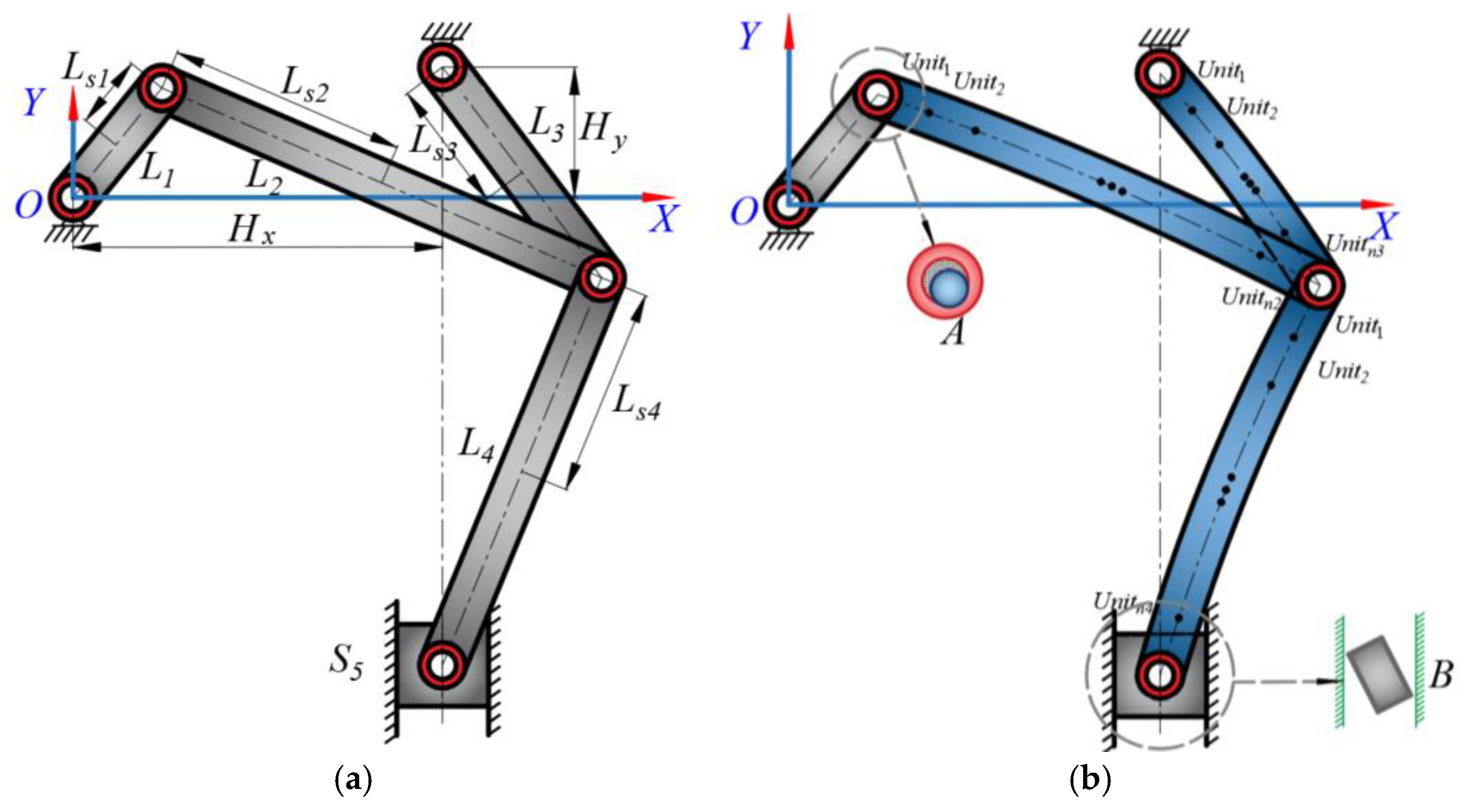
The schematic diagram of an ideal six-bar mechanism is shown in Figure 6a. The six-bar mechanism has the advantages of a low and stable operating speed of the end effector at the bottom dead center, good fast-return characteristics, good flexibility, and a strong load-bearing capacity. This configuration of a six-bar mechanism is highly suitable when it is integrated into the principal drive mechanism of a mechanical press. The schematic diagram of the mechanism with clearances and flexible elements is shown in Figure 6b. The clearance within the prismatic pair B, characterized by the space between the slider and its guideway, critically influences the system’s dynamics and precision, as the slider acts as the mechanism’s end effector. Consequently, careful consideration of the prismatic pair clearance is mandatory. The revolute joint A, linking crank 1 with rod 2, plays an integral role in the mechanism’s driving force transmission process. Thus, it is imperative to focus on revolute pair clearance A. Usually, the introduction of lubricating oil into the revolute pair serves to counteract the detrimental effects of wear and collision, thus enhancing the mechanism’s performance. Furthermore, the components L2, L3, and L4, by reason of their extended lengths, exhibit a higher susceptibility to elastic deformation, and are thus classified as flexible elements within the system.

Figure 6.
Schematic diagram of six-bar mechanisms. (a) Schematic diagram of an ideal six-bar mechanism. (b) Schematic diagram of mechanism with six-bar mechanism clearances and flexible elements.
Since crank 1 and slider 5 are regarded as rigid members, the generalized coordinates for crank 1 and slider 5 can be expressed as follows:
Since rods 2, 3, and 4 are flexible components, their generalized coordinates can be written as follows:
The generalized coordinates of the whole system can be written as follows:
The expression of constraint equation of the RFC-mechanism with lubrication revolute clearance and prismatic pair clearance is as follows:
The specific expression of constraint equation of the RFC-mechanism with lubrication revolute clearance and prismatic pair clearance has been placed in the Appendix A, and is shown in Equation (A4).
According to the Baumgarte stabilization method [18,30,50], the dynamic equation can be written as follows:
where Mf is the mass matrix, Φq is the Jacobian matrix of the constraint equation, Qf is the generalized force, Ff is the elastic force, λ is the Lagrange multiplier, and α and β are Baumgarte feedback parameters.
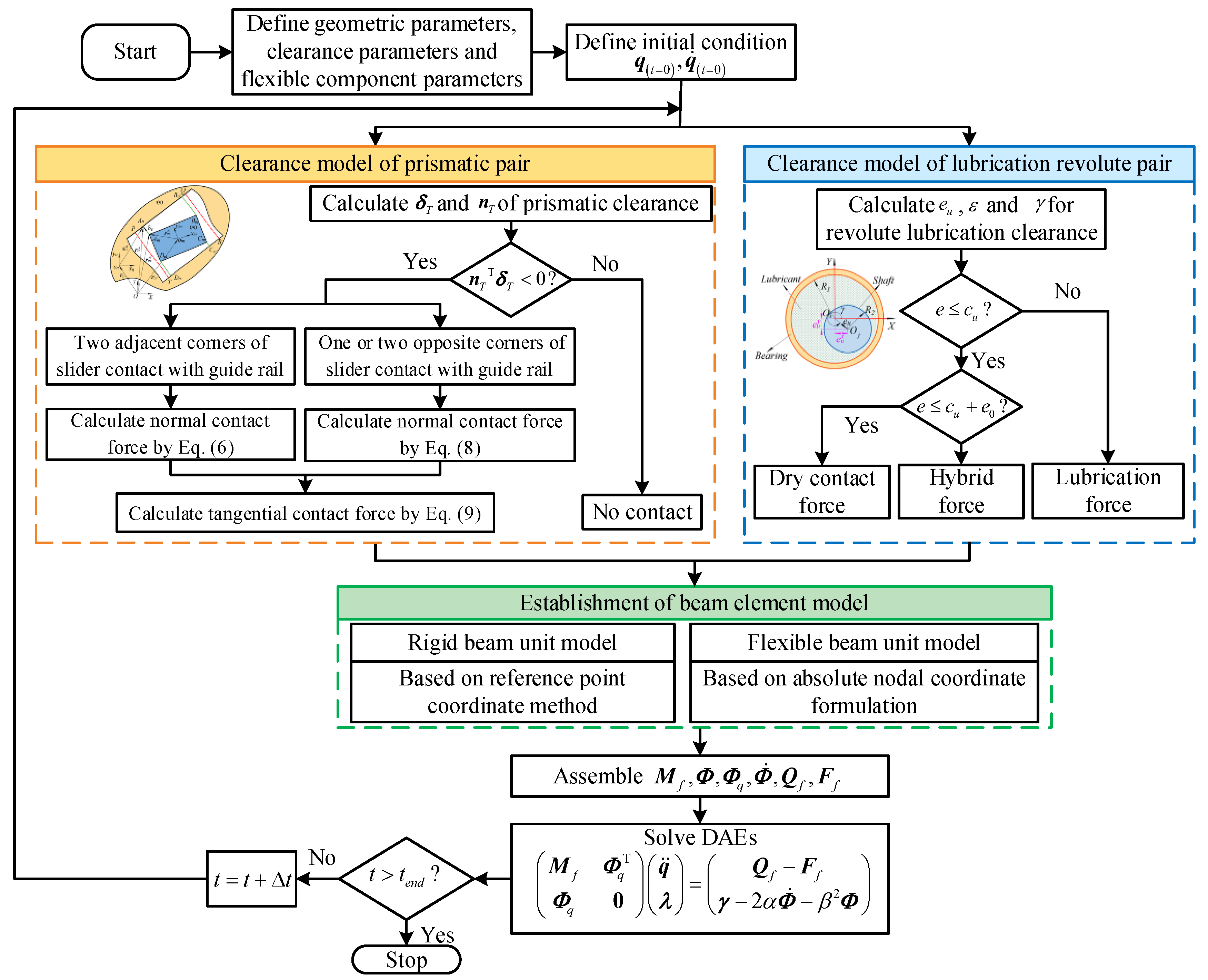
The flow chart for solving and establishing the dynamic equation is shown in Figure 7.
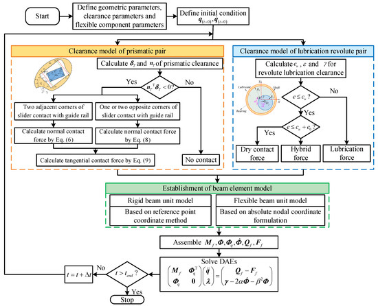
Figure 7.
Flow chart for modeling and solving the mechanism.
3. Nonlinear Dynamics Behaviour Analysis of RFC-MLM with Clearance
This chapter mainly includes the following contents: A comparative analysis of the effects of lubrication and dry friction revolute clearance on the dynamic behavior of an RFC-MLM, and an analysis of the effects of the driving speeds, dynamic viscosity, and clearance value on its dynamic behavior. The simulation parameters used in this article are shown in Table A1 and Table A2 in Appendix A.
3.1. Comparative Analysis of Lubrication and Dry Friction Revolute Clearance on Nonlinear Dynamics Behaviour of RFC-MLM
This section compares and analyzes the effects of lubrication revolute clearance and dry friction revolute clearance on the dynamic response and nonlinear characteristics of a six-bar mechanism.
3.1.1. Comparative Analysis of Dynamic Response
To assess the impact that dry friction and lubrication clearance exert on dynamic responses, the dynamics of mechanisms with dry friction revolute clearance and prismatic pair clearance or lubricated revolute clearance and prismatic pair clearance are examined in this section.
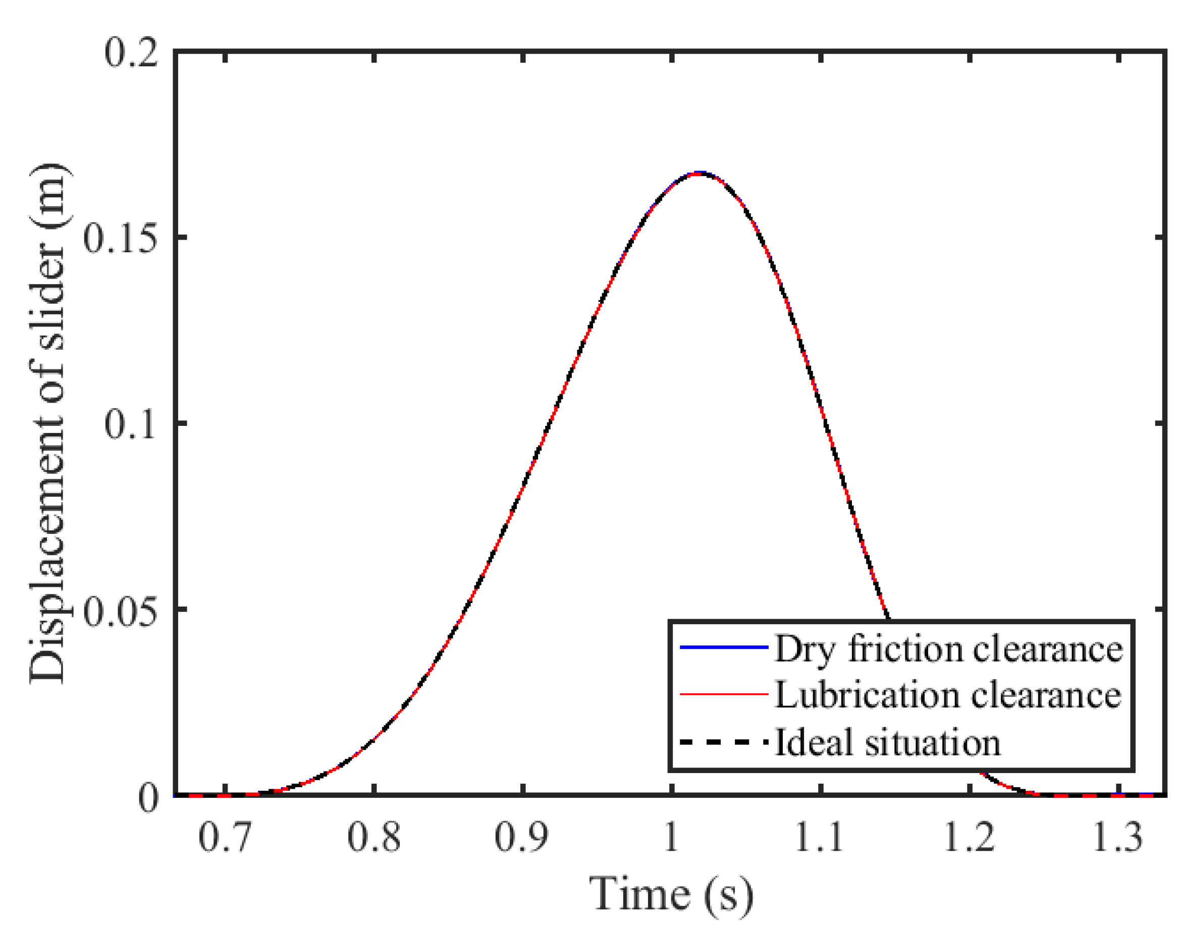
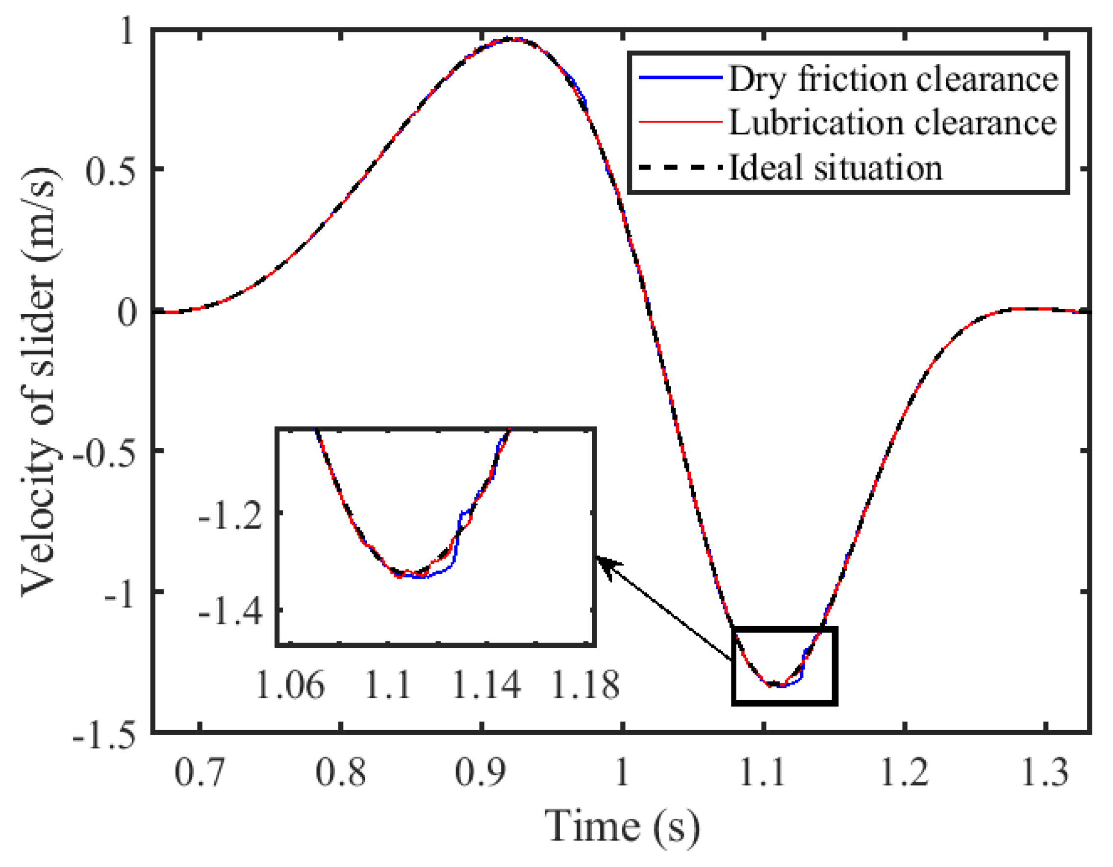
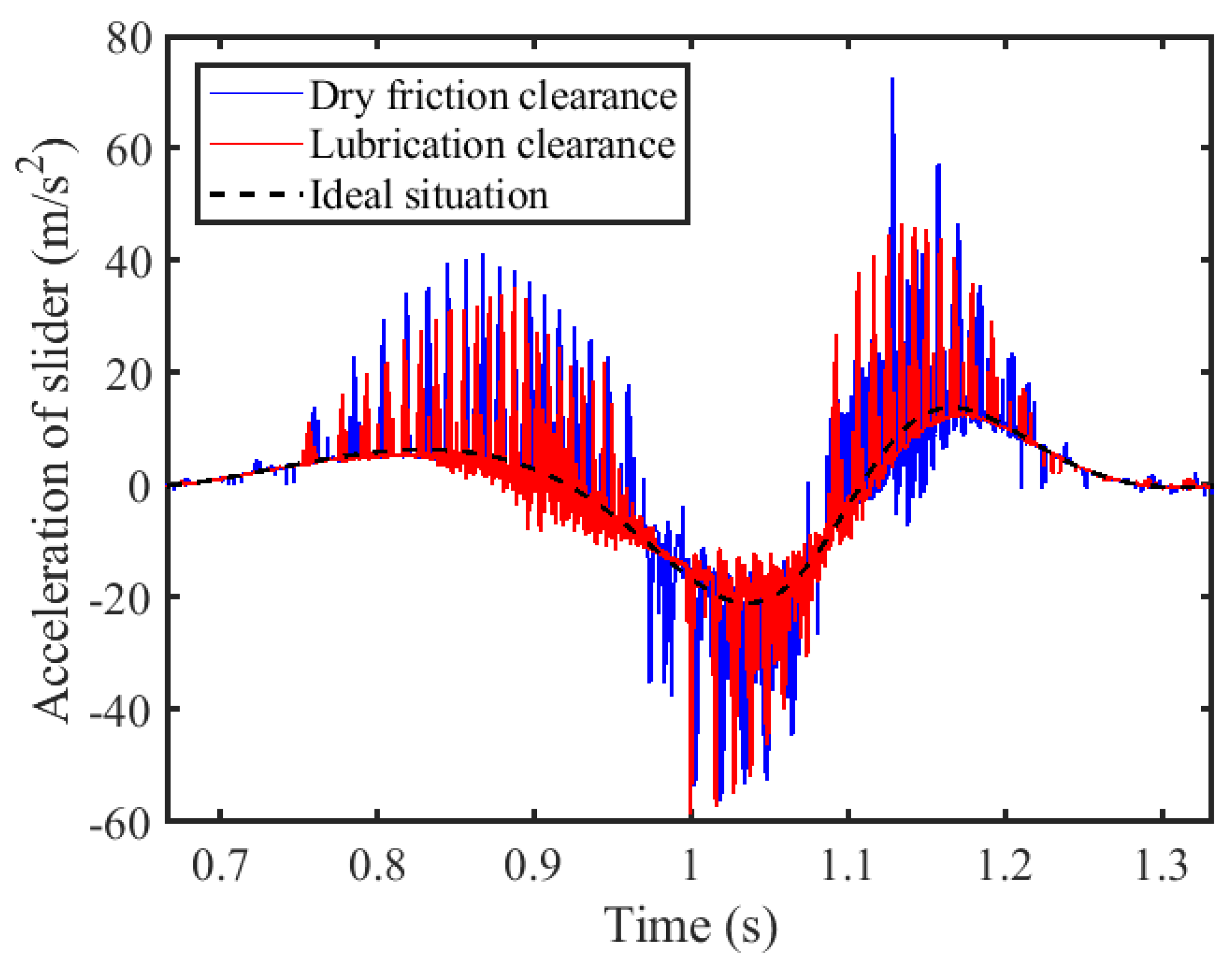
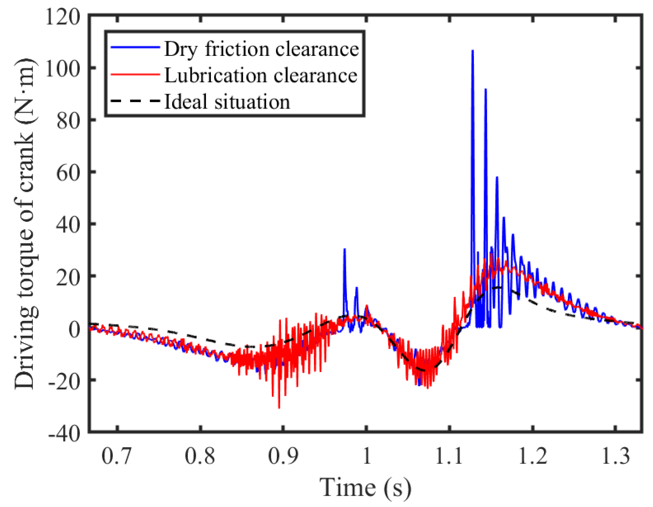
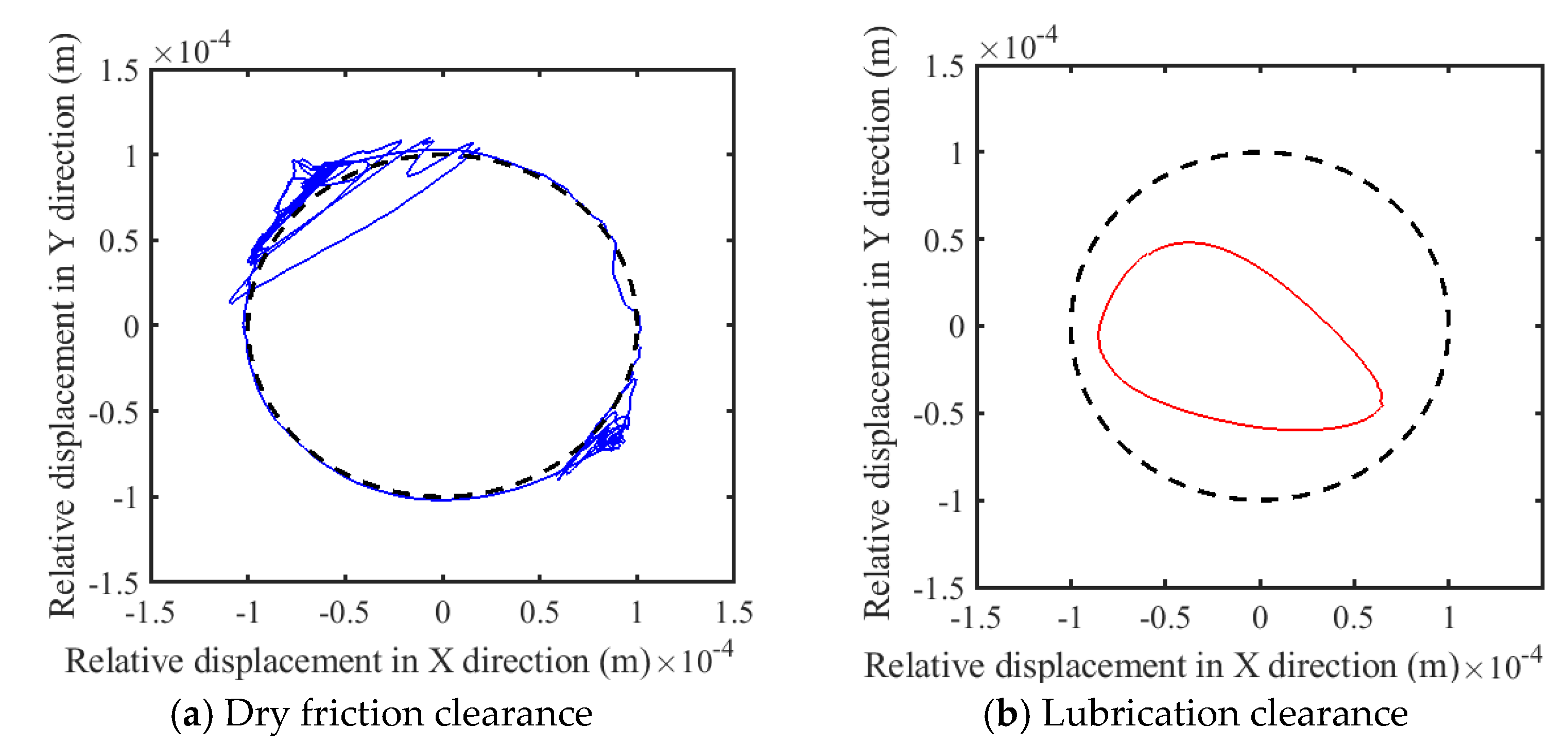
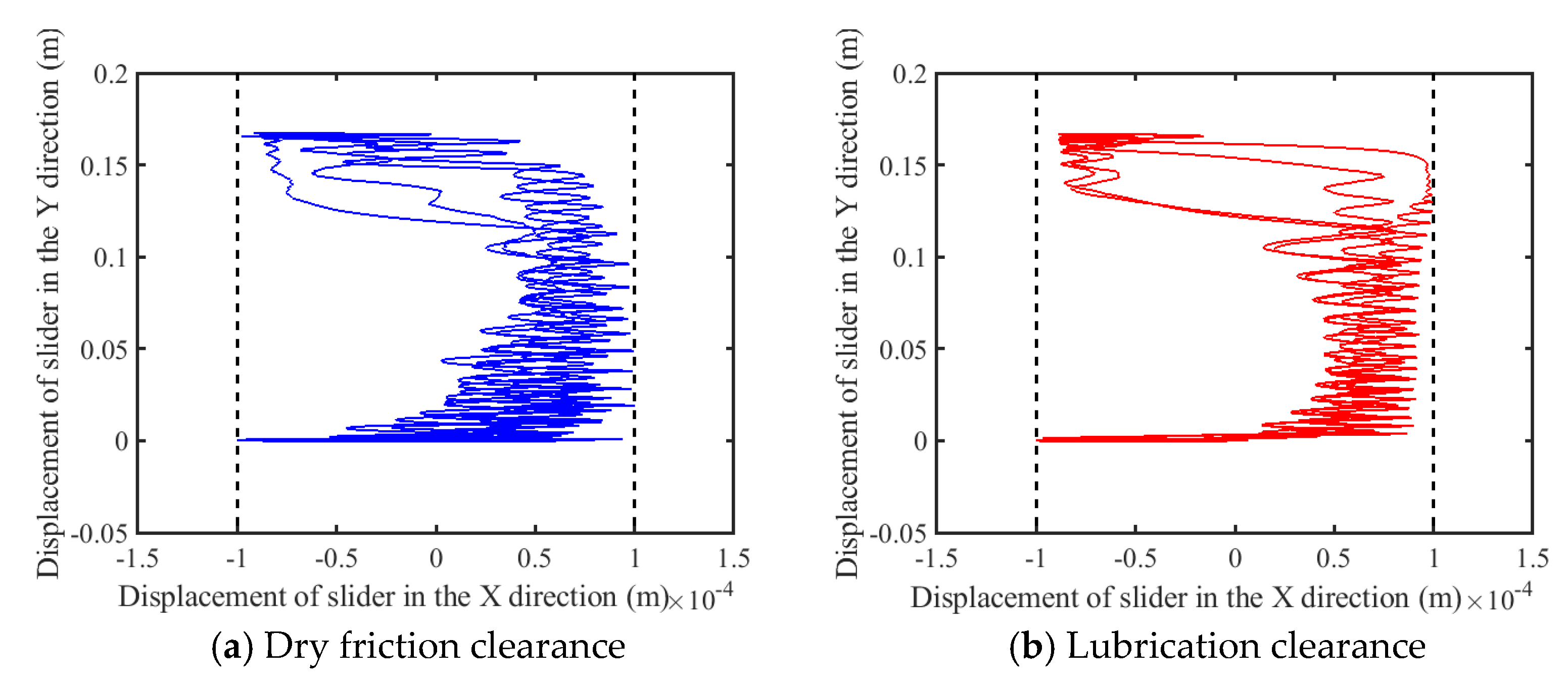
The mechanism was operated at a driving speed of 120 rpm, with a dynamic viscosity of 0.1 Cp at the lubricated clearance joint and a friction coefficient of 0.15 at the dry friction clearance joint. Both the revolute and prismatic pair clearances were set to a value of 0.1 mm. Figure 8, Figure 9 and Figure 10 illustrate the obtained motion characteristics curves. Figure 11 depicts the driving torque applied to the crank. Figure 12 and Figure 13 display the trajectories of the shaft and slider, respectively.
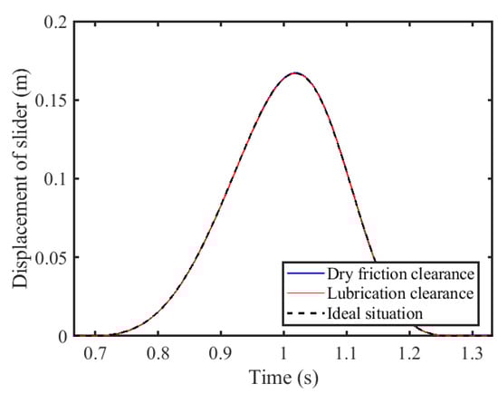
Figure 8.
Displacement of slider.
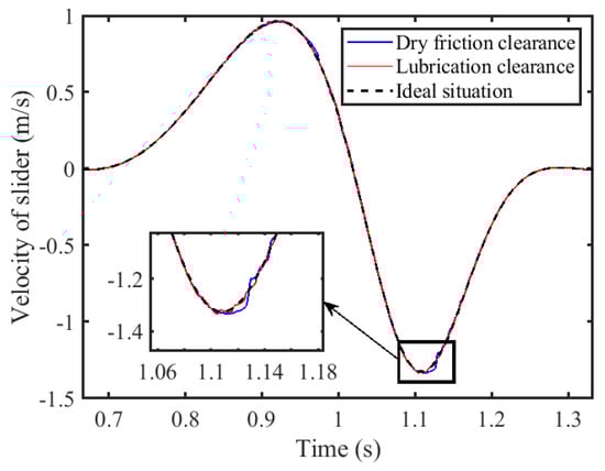
Figure 9.
Velocity of slider.

Figure 10.
Acceleration of slider.
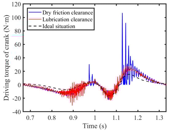
Figure 11.
Driving torque of crank.
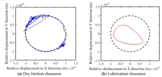
Figure 12.
Trajectory of shaft.
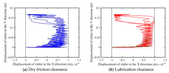
Figure 13.
Trajectory of slider.
It has been observed that the influence of dry friction and the presence of lubrication in the clearances exerts a minimal impact on the displacement and velocity of the slider. The discrepancy between the displacement profiles under these conditions and those in the ideal scenario is negligible. Additionally, only minor variations are present in the velocity profiles. Examining the speed fluctuations in greater detail reveals that dry friction clearances induce more pronounced deviations than when lubrication is employed. Given the slider’s formation of a prismatic pair through direct interaction with the guide rail under dry friction conditions, there is no requirement for a lubricating medium. When the mechanism operates with lubricated rotational and prismatic pair clearances, the vibration frequency of the slider’s acceleration curve is comparable to that of its dry friction counterparts, albeit with attenuated peak values. A reduction in the peak slider’s acceleration from 72.65 m/s2 to 46.55 m/s2, which equates to a decrease of approximately 35.93%, is observed. The pivotal role of clearance A, the connector between crank 1 and rod 2, is apparent from its pronounced effect on the torque that is exerted. Introducing lubrication into this junction, by adding lubricating oil to foster the formation of an oil film, mitigates the impact forces that arise due to the clearance. Consequently, lubrication leads to a significant reduction in the torque peak, which dwindles from 106.8 N·m to 28.73 N·m, which equates to a decrease of approximately 73.10%. The analysis of the central trajectory of the revolute pair illustrates that post-lubrication, the shaft’s motion trajectory is notably smoother in contrast to the chaotic patterns characteristic of dry friction scenarios. Furthermore, the trajectory of the slider within the prismatic clearance, despite the slider being subject to dry friction, approximates the ideal trajectory more closely and exhibits less disorder, a result attributed to the influence of lubricated clearance joint A. In summary, it is evident that the application of lubrication enhances the overall stability and performance of the mechanism.
3.1.2. Chaos Identification
In order to examine and evaluate the impact of both lubricated and dry friction clearances on the chaotic properties of a mechanism, this section presents a qualitative and quantitative investigation using phase diagrams, Poincaré maps, and the maximum Lyapunov exponent. Phase diagrams, Poincaré mapping, and the maximum Lyapunov exponent are three important tools in chaos identification, which reveal the dynamic behaviour of a system from different perspectives and help determine whether the system has chaotic characteristics.
- (1)
- Phase diagrams visually display the dynamic behaviour of a system by plotting the trajectories of system state variables in phase space;
- (2)
- Poincaré maps transform a continuous system into a discrete map by selecting a section in phase space and recording the state of the system trajectory each time it passes through that section. If the system is chaotic, the Poincaré map will display a complex distribution of points, which will not converge to a finite number but form a seemingly random distribution;
- (3)
- The maximum Lyapunov exponent quantifies the average exponential rate at which adjacent trajectories diverge or converge in phase space, and is a key indicator for determining chaotic behaviour. If the maximum Lyapunov exponent of a system is positive, it indicates that the adjacent trajectories will diverge exponentially, which is a sign of chaotic behaviour. If the maximum Lyapunov exponent is zero, the system may be periodic or quasi periodic. If it is negative, the system tends to be stable and there is no chaotic behavior.
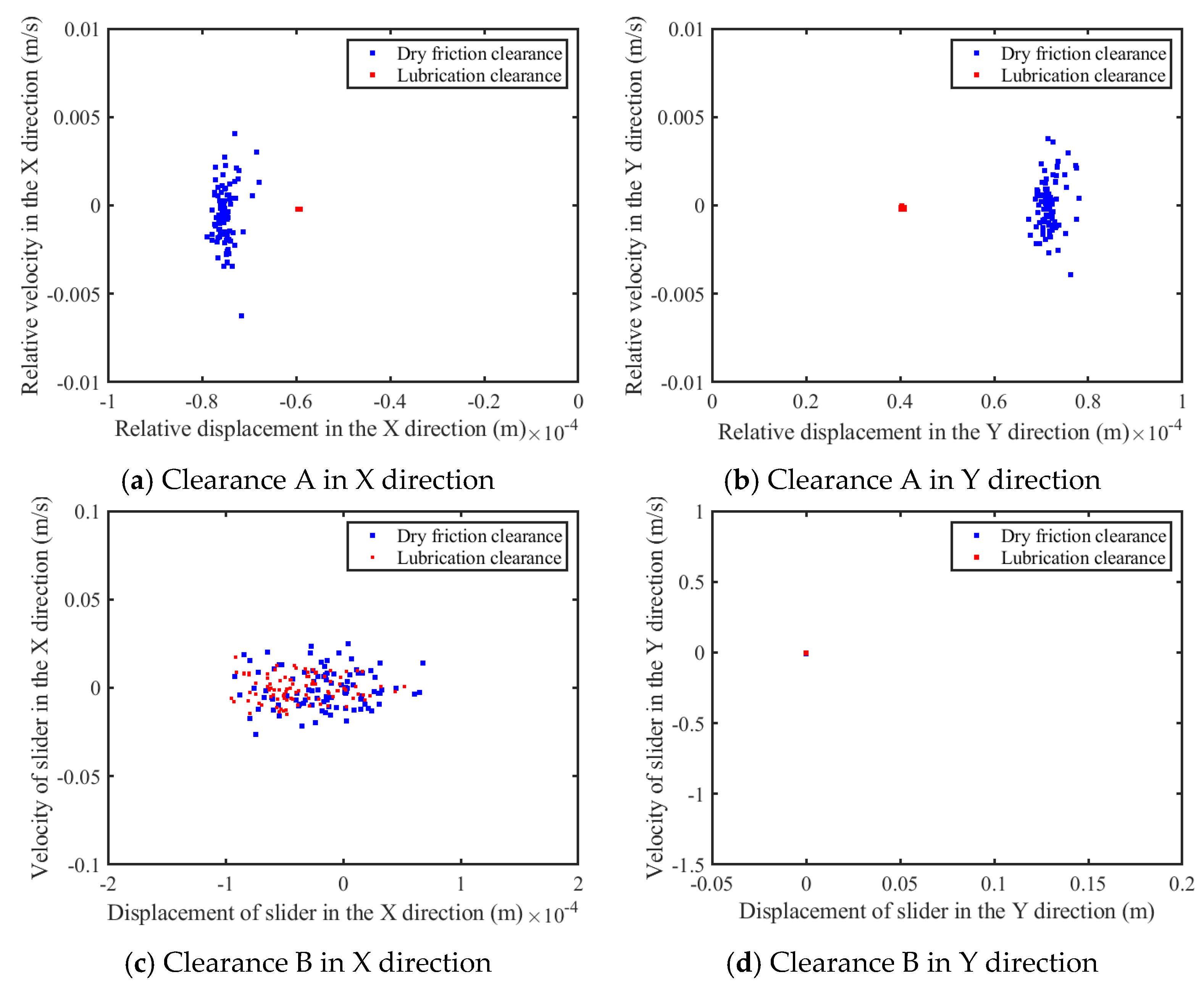
By analyzing a dataset spanning 100 operational cycles, phase diagrams and Poincaré maps were constructed. The results are depicted in Figure 14 and Figure 15. As shown in Figure 14a,b and Figure 15a,b, according to the phase diagram and the Poincaré map of the revolute clearance, when lubrication is added to the rotating pair, the area of the phase diagram significantly shrinks and the points on the Poincaré diagram significantly gather, indicating that the motion state at the clearance of the rotating pair gradually becomes stable. As shown in Figure 14c,d and Figure 15c,d, according to the phase diagram and Poincaré map of the prismatic pair clearance, the chaotic behaviors observed in the prismatic pair’s clearance receive some mitigation from the effects of the lubricating layer. The Poincaré map and phase diagram for the slider along the x-axis exhibit some degree of convergence as a result of the lubricant’s influence on revolute clearance A, yet the system still tends toward chaos. An examination of the phase diagram, enlarged for clarity, reveals that the revolute pair’s lubricant layer imparts a stabilizing effect on the slider’s y-axis motion. Due to the aggregation of mapping points in the Poincaré map of the slider in the Y direction into a single point, rather than scattered points, this indicates that the chaotic phenomenon regarding the slider’s motion in the Y direction is weak. This is primarily due to the diminutive impact of clearance-induced disturbances compared to the inherent motion characteristics of the mechanism.
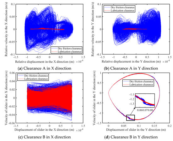
Figure 14.
Phase diagrams of clearance.
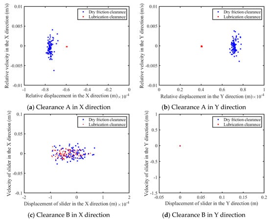
Figure 15.
Poincaré maps of clearance.
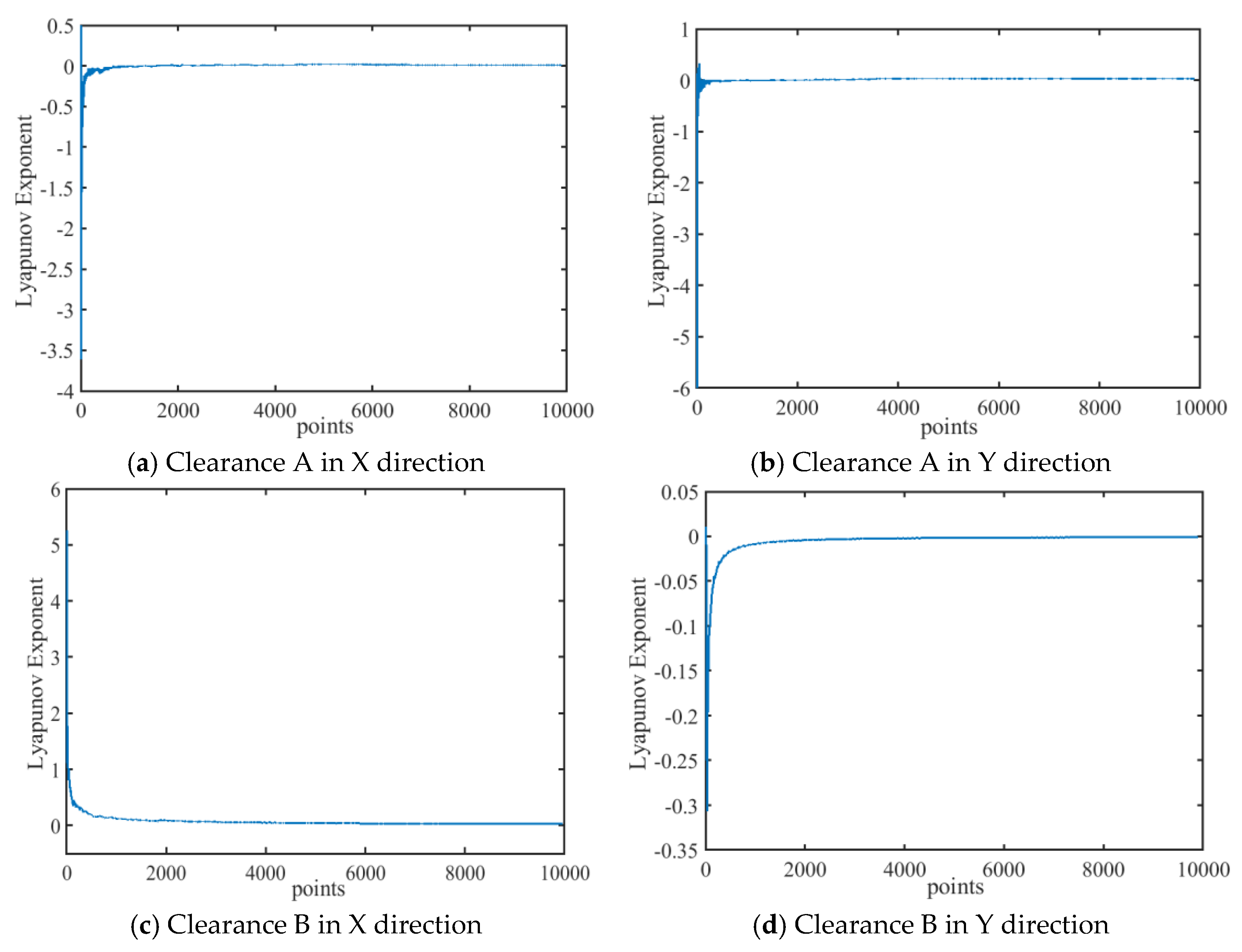
The maximum Lyapunov exponent is calculated based on the eccentricity of the clearance in the X and Y directions. An MLE is shown in Figure 16 and Figure 17, and MLEs for both the revolute and prismatic pairs with clearance before and after lubrication are shown in Table 1. The MLE of clearance A after lubrication decreases and is less than 0, indicating that lubrication clearance A is more stable compared to that before lubrication. The revolute clearance is observed transitioning from chaos to periodicity upon lubrication, and, similarly, the chaotic phenomena in the prismatic pair with clearance along the X-axis are dampened, whereas the prismatic pair clearance along the Y-axis consistently sustains a periodic motion state.
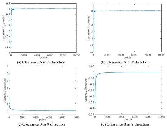
Figure 16.
LLEs of mechanism with dry friction clearance.
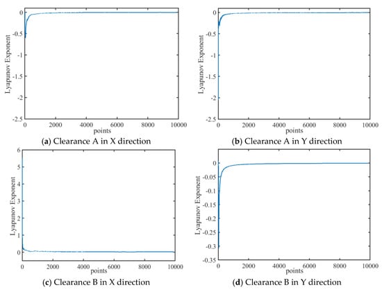
Figure 17.
MLEs of mechanism with lubrication clearance.

Table 1.
MLEs of clearance joints.
3.2. Influence of Different Driving Velocity on Dynamic Behaviour
In order to study the effect of different driving speeds on dynamics, this section selects different driving speed values and studies the dynamic response and nonlinear characteristics of the mechanism.
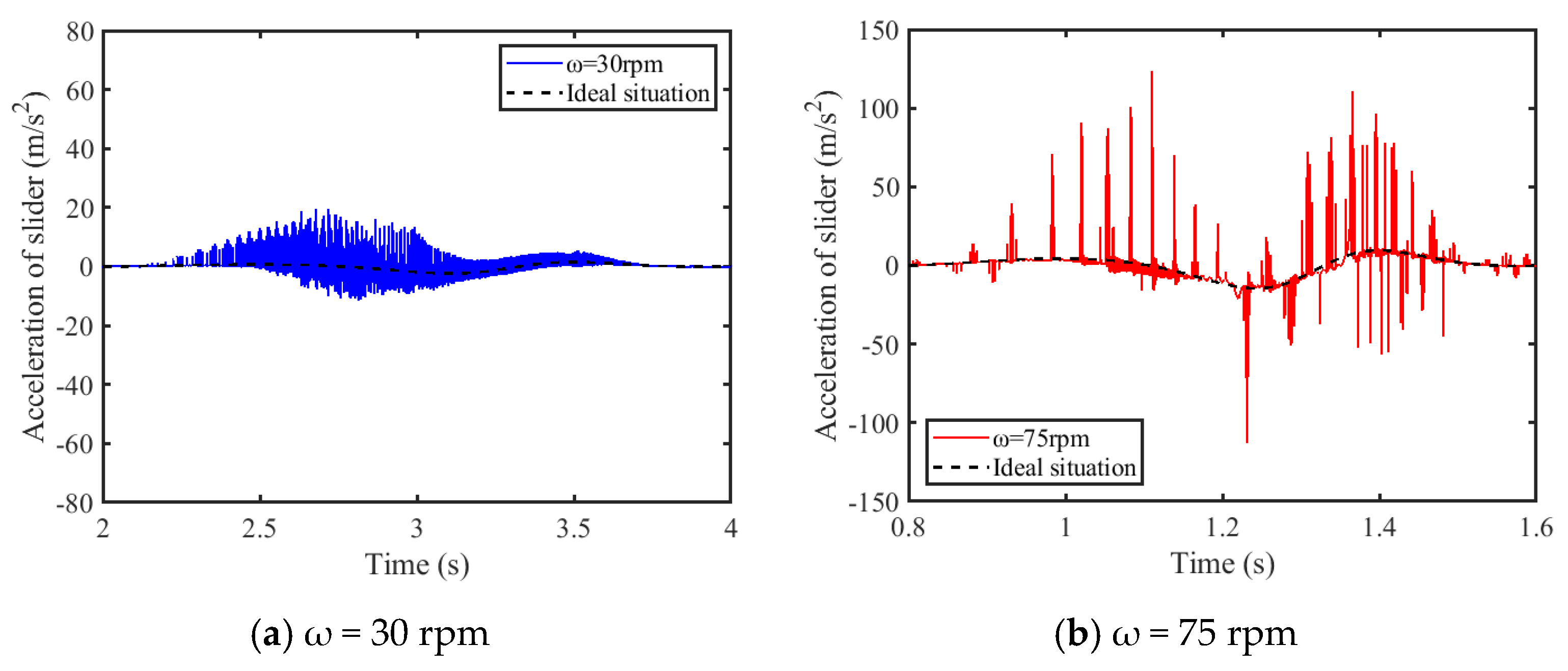
3.2.1. Analysis of Dynamics Response
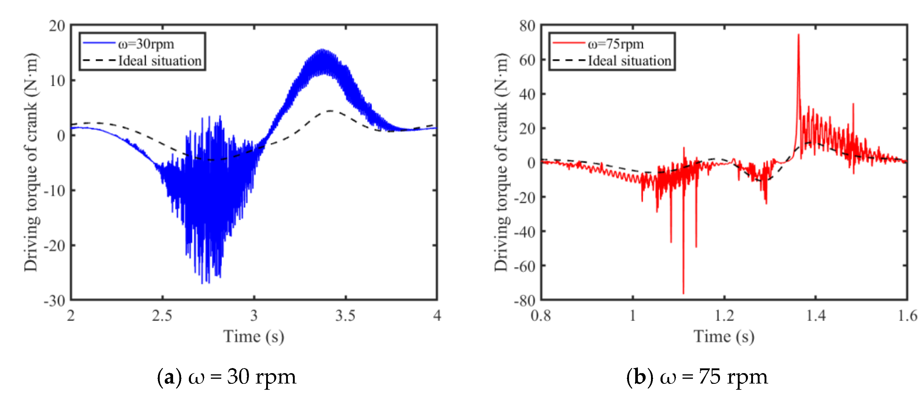
In this section, in order to analyze the effect of driving speeds on dynamics responses, the dynamic responses when driving speeds are 30 rpm and 75 rpm, respectively, are compared and analyzed. Figure 18 and Figure 19, respectively, display the slider’s acceleration and the crank’s torque under different driving speeds. Upon comparative analysis of the slider’s acceleration and the crank’s driving torque curves across a range of driving speeds, it is observed that the dynamic response peaks escalate with an increase in driving velocity. An upsurge in driving speed from 30 rpm to 75 rpm results in an elevation of the peak acceleration of the slider from 19.55 m/s2 to 123.6 m/s2, constituting approximately an 84.18% increase; concurrently, the torque peak ascends from −27.11 N·m to −76.62 N·m, marking an increment of roughly 64.62%. It is inferred that the stability of the mechanism is inversely proportional to the driving speed, with higher velocities inducing reduced stability.

Figure 18.
Acceleration of slider.
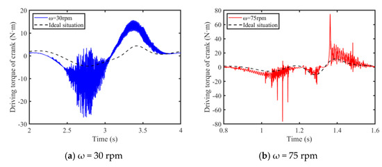
Figure 19.
Driving torque of crank.
3.2.2. Analysis of Nonlinear Characteristics
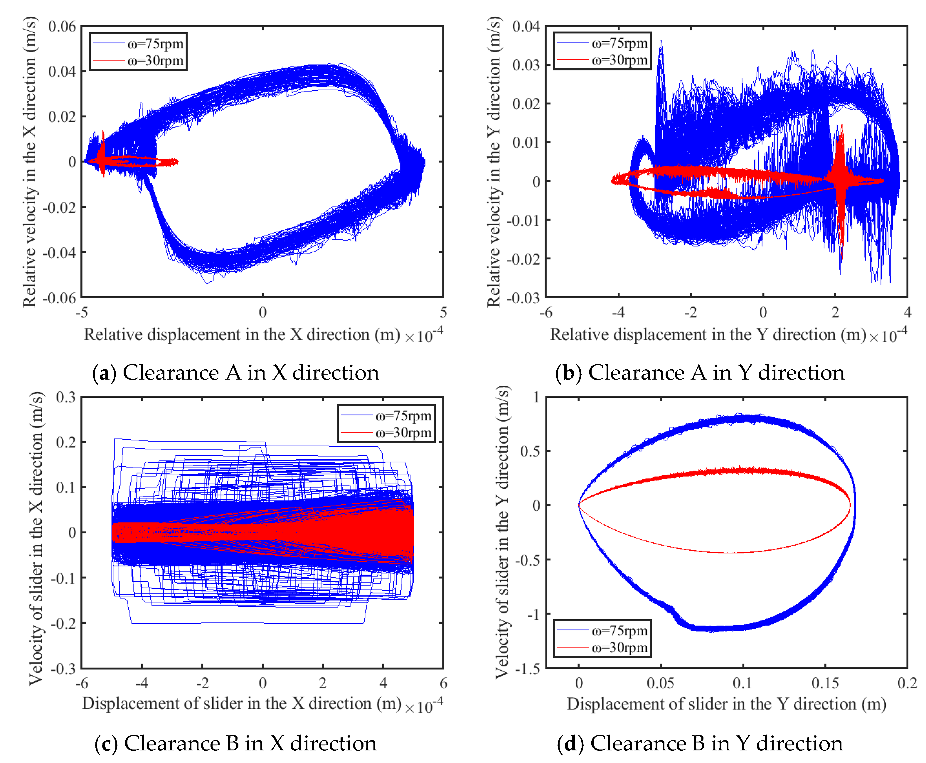
This section analyzes the nonlinear characteristics of a rigid–flexible coupled six-bar mechanism with lubricated revolute and translational clearance under different driving speeds through phase diagrams and Poincaré mapping diagrams.
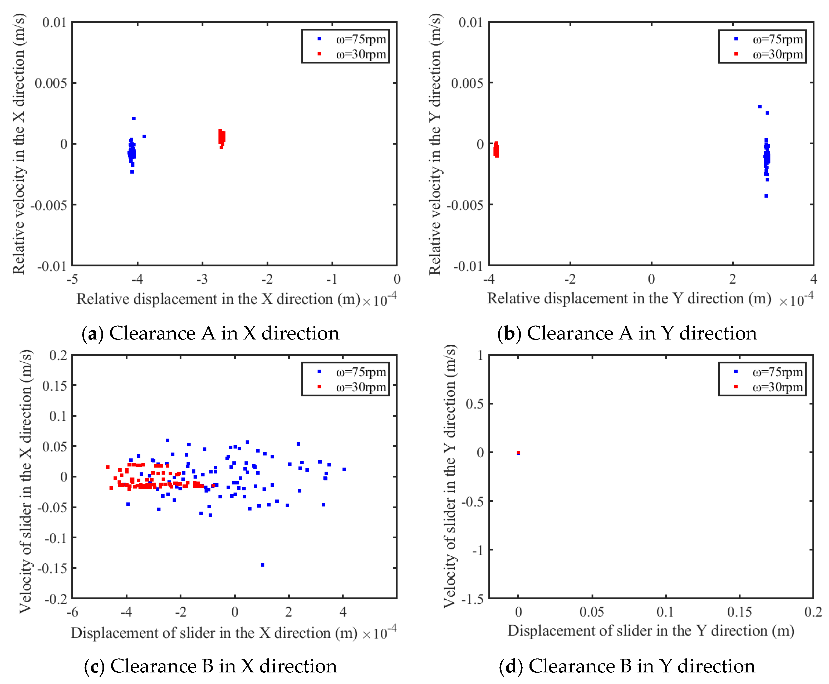
This investigation examines the nonlinear attributes of both translational and revolute pairs featuring clearance through an analysis of data obtained from a series of 100 cycles. Figure 20 is the phase diagram, while Figure 21 presents the Poincaré map. As shown in Figure 20a–c and Figure 21a–c, as the driving speed increases, the area of the phase diagram at clearance increases at different levels, and the Poincaré mapping points gradually discretize, indicating an increase in the degree of chaos of the system. As shown in Figure 20d and Figure 21d, due to the small influence of clearance on the movement of the slider in the Y direction, it is worth noting that the phase diagram of the prismatic pair clearance in the Y direction presents a relatively regular closed shape, and the Poincaré map shows a closed point, which means that the slider exhibits periodic motion in its direction of motion.

Figure 20.
Phase diagram of clearance.
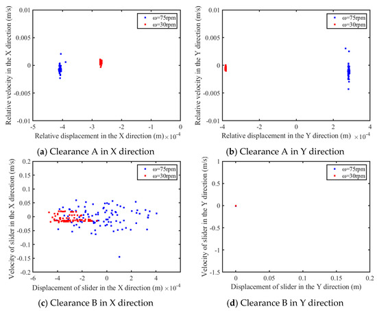
Figure 21.
Poincaré map of clearance.
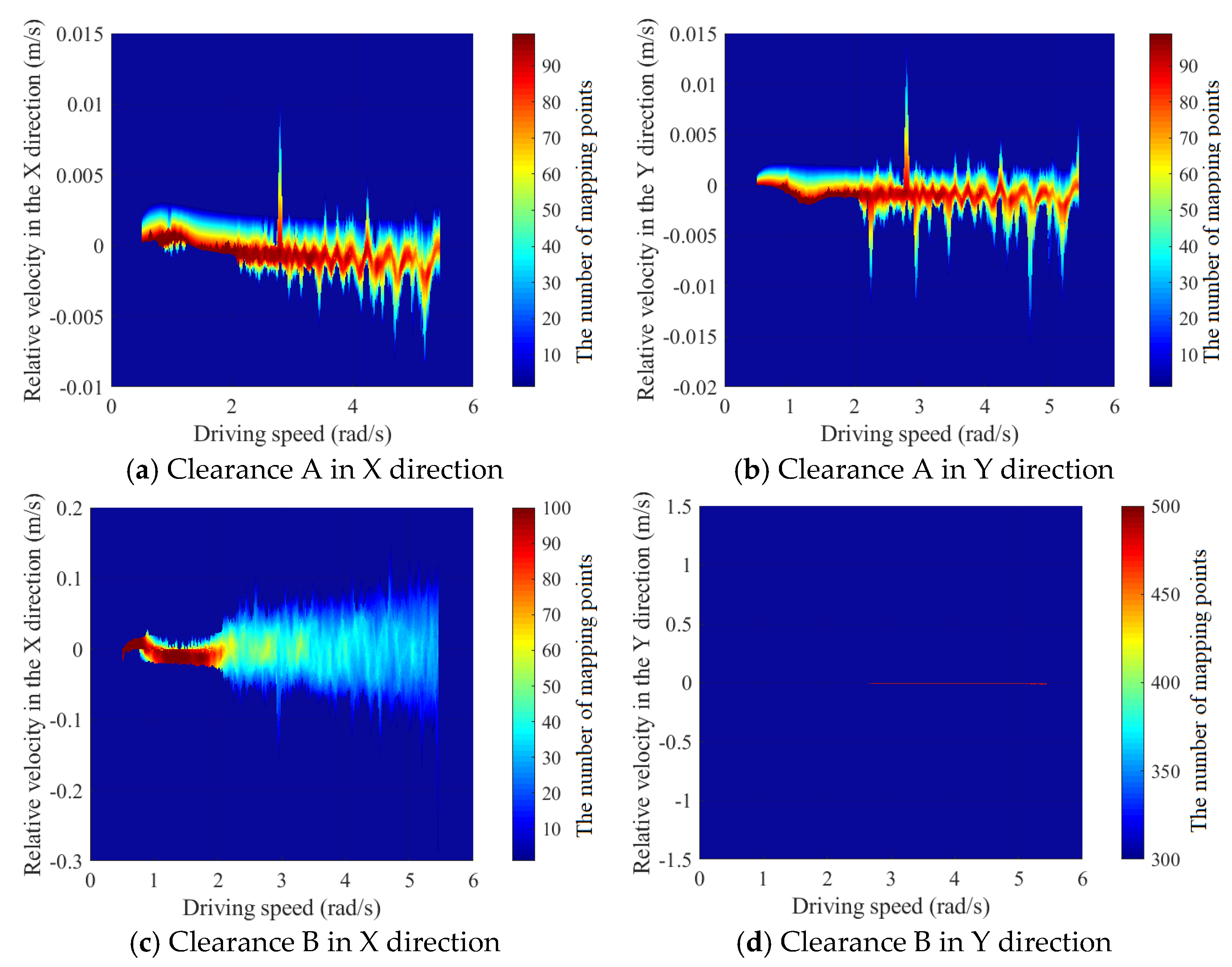
The trend of the motion state at clearance changing with the driving speed is demonstrated in Figure 22. The meanings of the colors in Figure 22 are as follows: Red indicates that the data points are more clustered. The transition from red to blue indicates that the data points are transitioning from clustered to sparse.
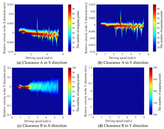
Figure 22.
The trend of the motion state at the clearance changing with the driving speed.
According to Figure 22, as the driving speed increases, the data points in rotational pair A and prismatic pair B along the X-axis gradually spread. This diffusion primarily stems from the heightened frequency of collisions and the intensifying force of impact between the shaft and the slider due to the increased driving speed, which augments the system’s chaotic traits. Conversely, prismatic pair B and clearance pair B’s motion in the Y-axis remains relatively unaffected by variations in driving speed, consistently maintaining a state of periodic motion.
3.3. Influence of Various Dynamics Viscosity on Dynamic Behaviour
In order to study the influence of dynamic viscosity on the dynamics of mechanisms, this section conducts a detailed study on the dynamic response and nonlinear characteristic of mechanisms with different dynamic viscosity values.
3.3.1. Analysis of Dynamics Response
This section investigates the influence of two different dynamic viscosity values on the dynamic response of the mechanism, mainly focusing on the acceleration of the slider and the driving torque of the crank.
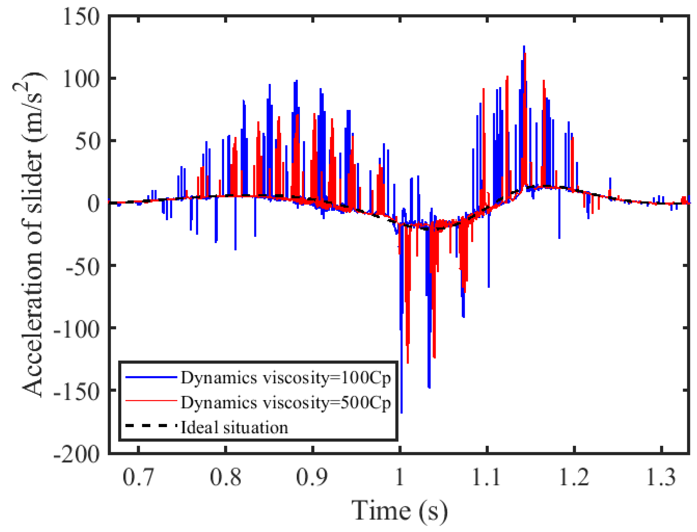
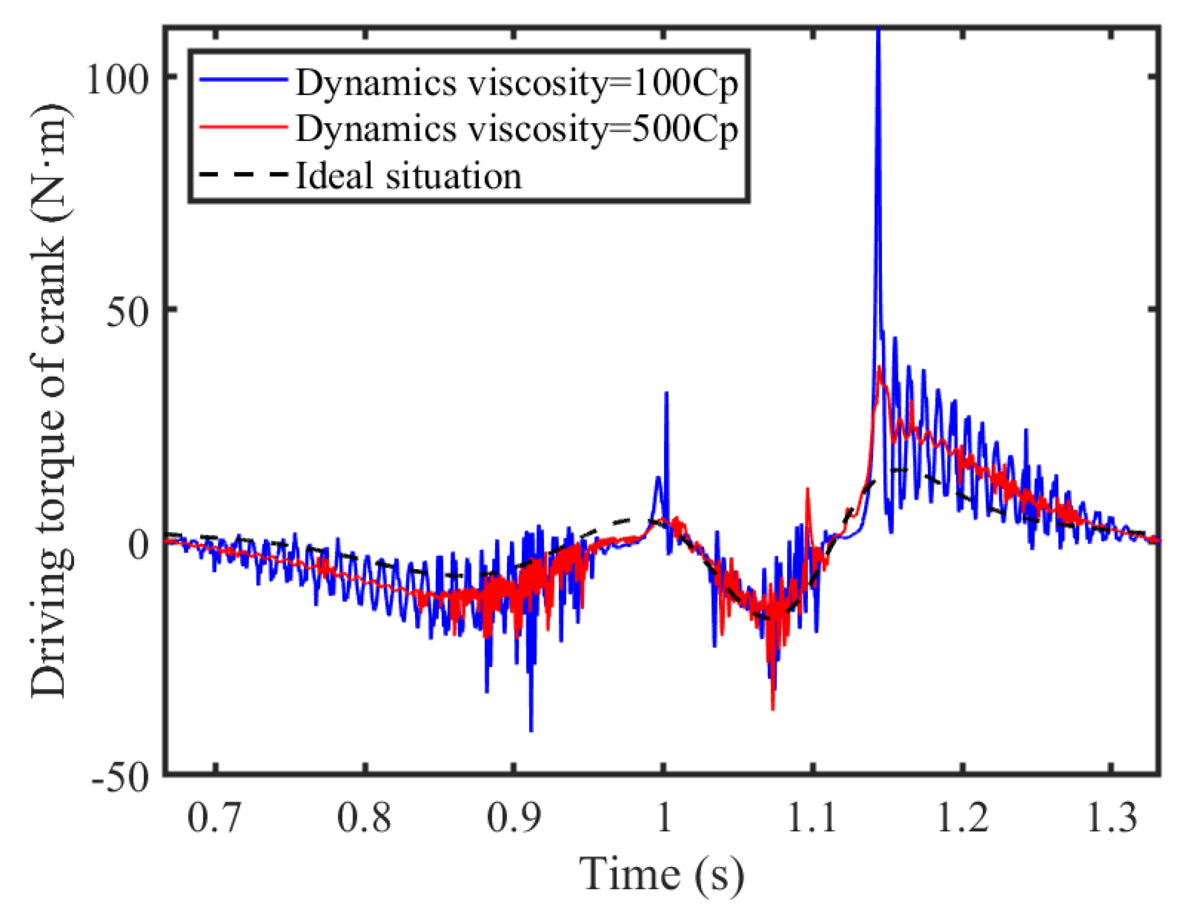
The dynamic performance is predominantly influenced by the viscosity of the lubricating oil. Within this segment of the analysis, the effect of the viscosity on the system dynamics is studied by comparing two distinct viscosities, precisely 100 Cp and 500 Cp. Figure 23 and Figure 24 illustrate, respectively, the acceleration of the slider and the driving torque of the crank.

Figure 23.
Acceleration of slider.
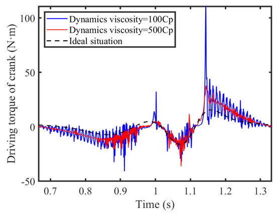
Figure 24.
Driving torque of crank.
With the decrease in lubrication viscosity, the vibration within the clearance of the hinge becomes more pronounced. This reduced viscosity leads to closer proximity between the shaft and bearing surfaces, raising the risk of direct metal-to-metal contact as a result of oil-film breakdown. Consequently, as the viscosity at the revolute clearance diminishes, so too does the stability of the revolute pair, causing chaos in the slider’s motion, which deviates from its intended path and signifies a reduction in system stability. The presence of lubrication at revolute pair A significantly influences the crank’s driving torque; when the viscosity of this lubricating fluid is reduced from 500 Cp to 100 Cp, there is a substantial decline in the peak torque value from 110.7 N·m to 38.02 N·m, a reduction of 65.65%. On the other hand, the dry friction clearance between the slider and guide rail means that the acceleration of the slider is less sensitive to changes in lubrication viscosity at the lubricated revolute pair; here, the peak of the slider’s acceleration drops from −168.1 m/s2 to 128.3 m/s2, a 23.68% decrease. Overall, it is advantageous to maintain a higher lubrication viscosity in order to enhance the stability of the mechanism.
3.3.2. Analysis of Nonlinear Characteristics
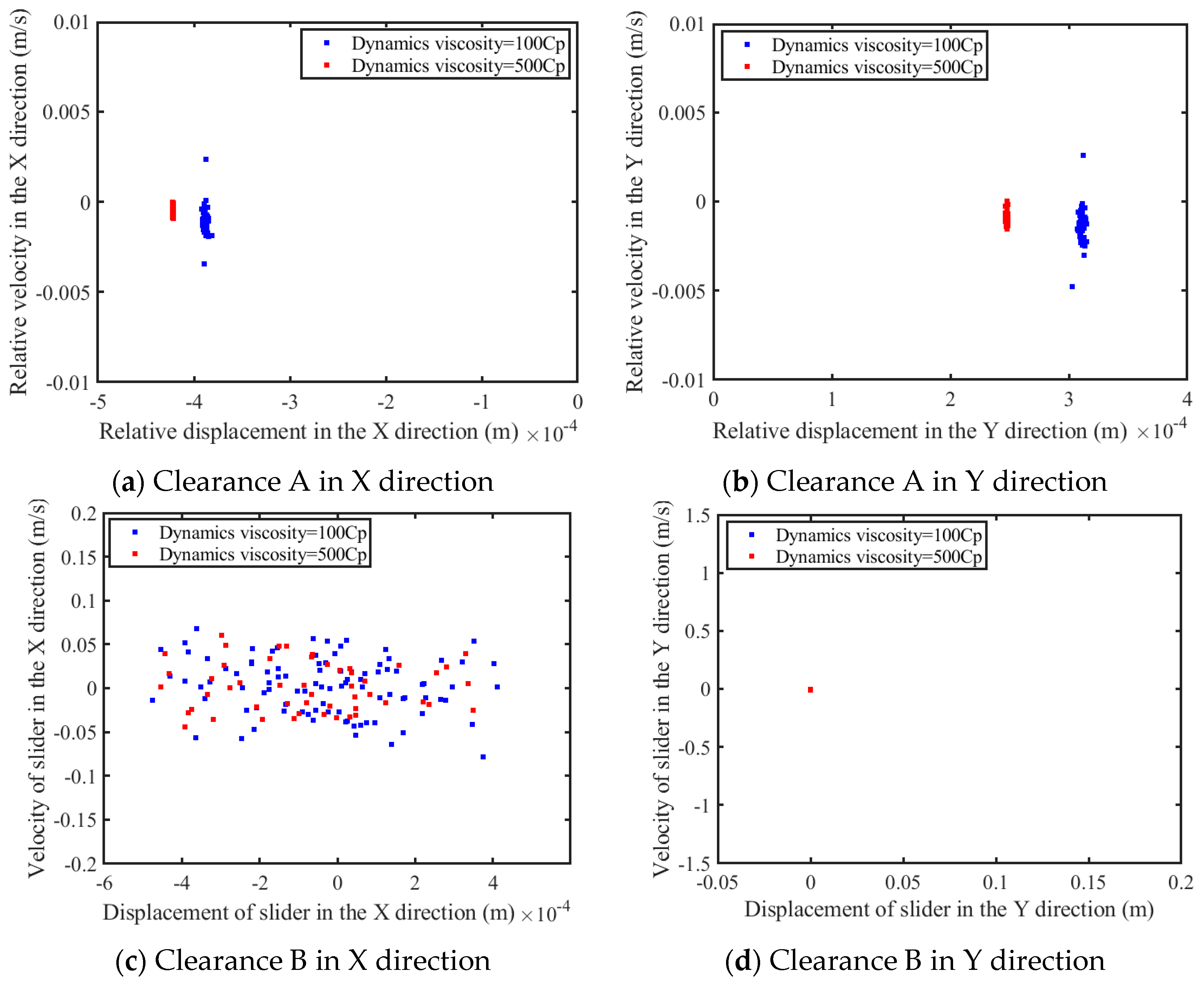
This section investigates the nonlinear characteristics of mechanisms under various dynamic viscosity conditions through phase diagrams and Poincaré maps.
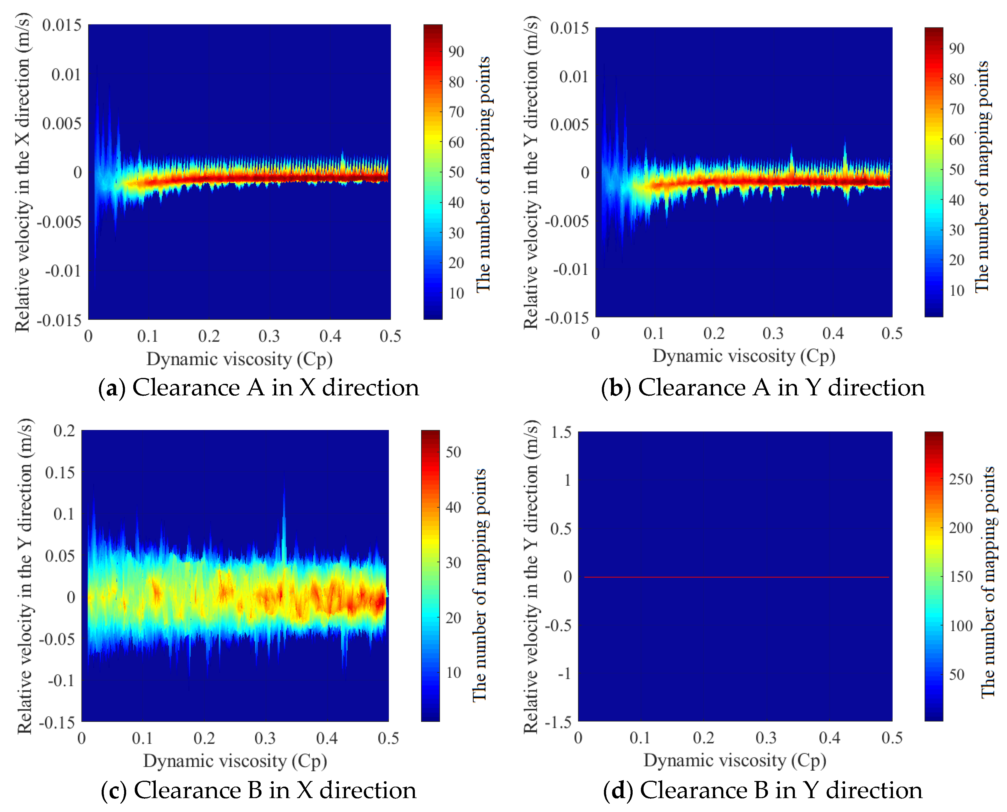
Figure 25, Figure 26 and Figure 27 present the that the results of our investigation of the nonlinear properties inherent in the revolute and prismatic pair clearances, the findings of which have been derived from an analysis of the mechanism over a span of 100 cycles. The meanings of the colors in Figure 27 are as follows: Red indicates that the data points are more clustered. The transition from red to blue indicates that the data points are transitioning from clustered to sparse.
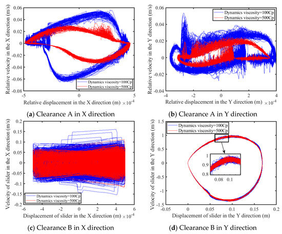
Figure 25.
Phase diagram of clearance.
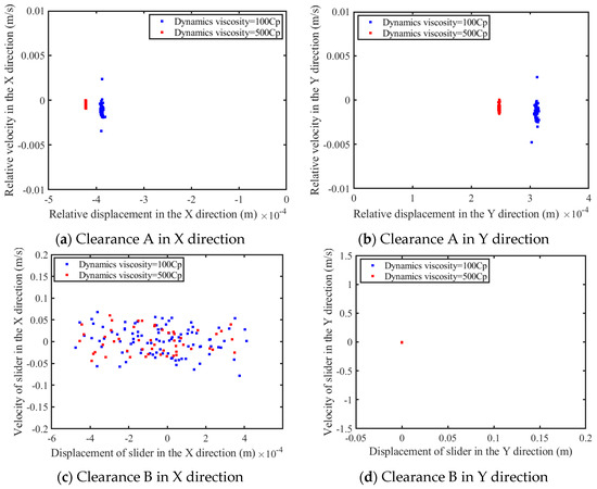
Figure 26.
Poincaré map of clearance.
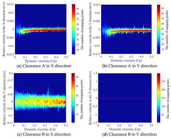
Figure 27.
The trend of the motion state at the clearance changing with dynamics viscosity.
It has been illustrated by phase the diagrams (shown in Figure 25) that, as the dynamic viscosity experiences an increment, transitioning from 100 Cp to 500 Cp, there is a corresponding decrease in both the area and the complexity of the phase diagrams for both the revolute pair and the prismatic pair with clearance when examined along the X-axis. In terms of sensitivity to dynamic viscosity changes, the phase diagrams for the prismatic pair with clearance observed along the y-axis exhibit a less pronounced responsiveness. There is a slight change in the local enlarged diagram. With the increase in the dynamic viscosity, the phase map converges to a certain extent. As the dynamic viscosity progresses between 100 Cp and 500 Cp, analysis of the Poincaré maps (shown in Figure 26) reveals that the scatter of points representing both revolute and prismatic pair clearances along the X-axis diminishes, whereas the Poincaré maps along the Y-axis for the prismatic pair depict an isolated point, representing a periodic motion in the prismatic pair clearance within the y-axis. Figure 27 reinforces the observation that an augmentation in dynamic viscosity corresponds to the mechanism’s motion state tending towards stabilization; concurrently, the trend of the motion state diagrams for both rotational clearance A and prismatic pair clearance B in the x-axis evince a converging pattern, which is particularly noticeable in the case of the rotational clearance pair. Lastly, the trend of the motion state map for prismatic pair clearance B in the y-axis direction comprises a sequence of discrete points, indicative of a recurring periodic motion manifested by prismatic pair clearance B in the y-axis direction.
3.4. Influence of Various Clearance Value on Dynamic Behaviour
Different clearance values have a significant influence on the dynamic response and nonlinear characteristic of a mechanism. This section analyzes the dynamic response and nonlinear characteristics of mechanism for different clearance sizes.
3.4.1. Analysis of Dynamics Response
In order to analyze the influence of different clearance values on the dynamic response of the mechanism, this section presents the acceleration of the slider and the driving torque of the crank under different clearance sizes.
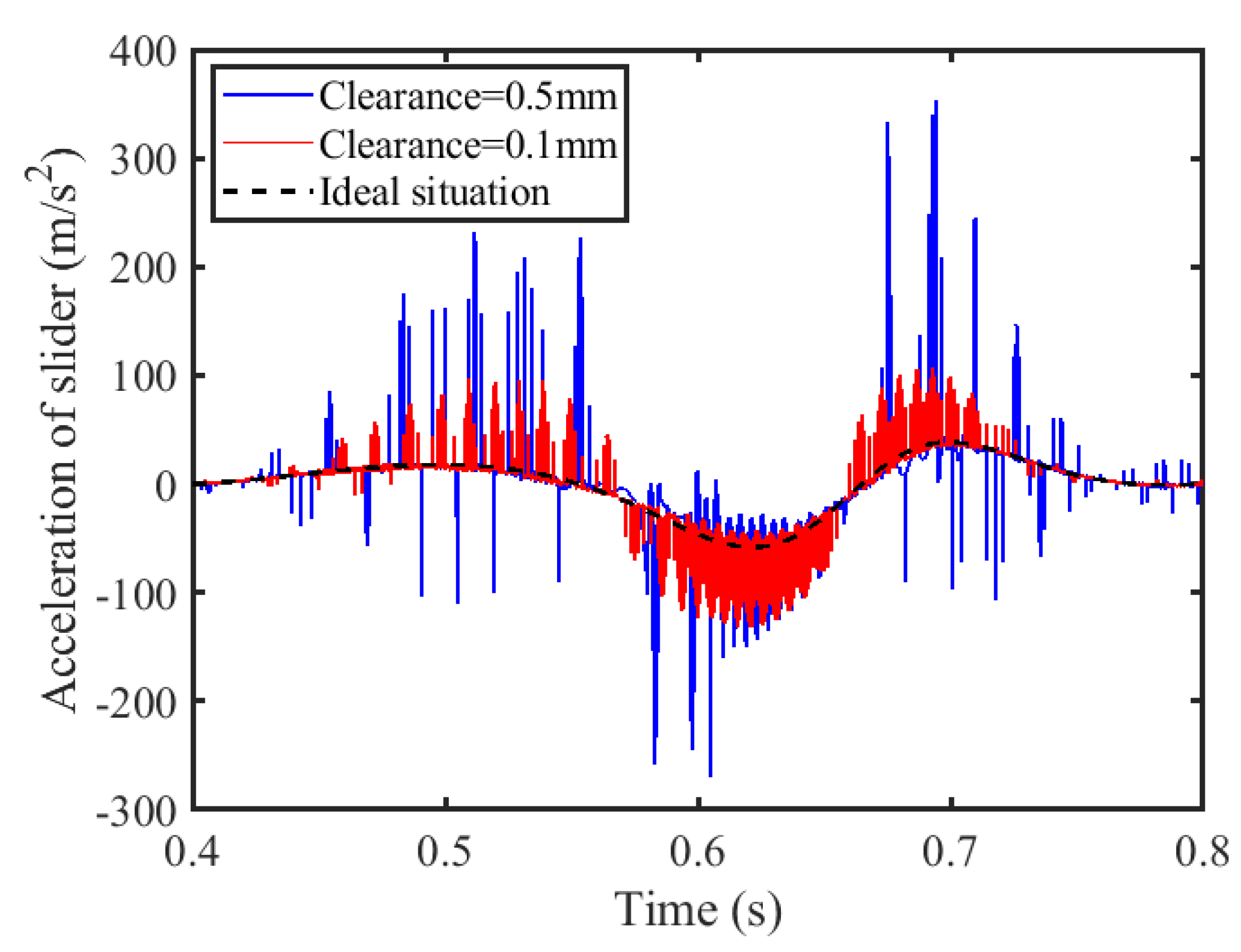
The impact of varying clearance values at the clearance joint—specifically 0.1 mm and 0.5 mm—on the slider’s acceleration and the crank’s driving torque is depicted in Figure 28 and Figure 29. Examination of the slider’s acceleration and the cranks’s driving torque curves reveals that mechanisms with smaller clearance values exhibit higher frequencies in the acceleration of the slider and the torque curves of the crank, while their peak values are comparatively diminished. The primary cause of this is the inverse relationship between the clearance size and collision force; the smaller the clearance, the less forceful the collision, and hence the lower the peak values. As the clearance expands from 0.1 mm to 0.5 mm, there is a notable increase in the peak acceleration of the slider—from 107.2 m/s2 to 353.3 m/s2, which is an approximate rise of 69.66%. Similarly, the peak value of the driving torque of the crank surges from 53.86 N·m to 294.6 N·m, marking an increase of roughly 81.72%.
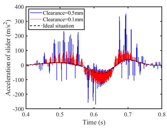
Figure 28.
Acceleration of slider.
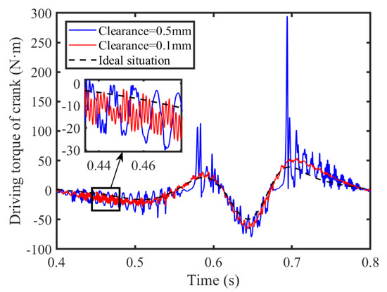
Figure 29.
Driving torque of crank.
3.4.2. Analysis of Nonlinear Characteristics
This section compares and analyzes the nonlinear characteristics of the mechanism under different clearance values through the use of phase diagrams and Poincaré mapping diagrams.
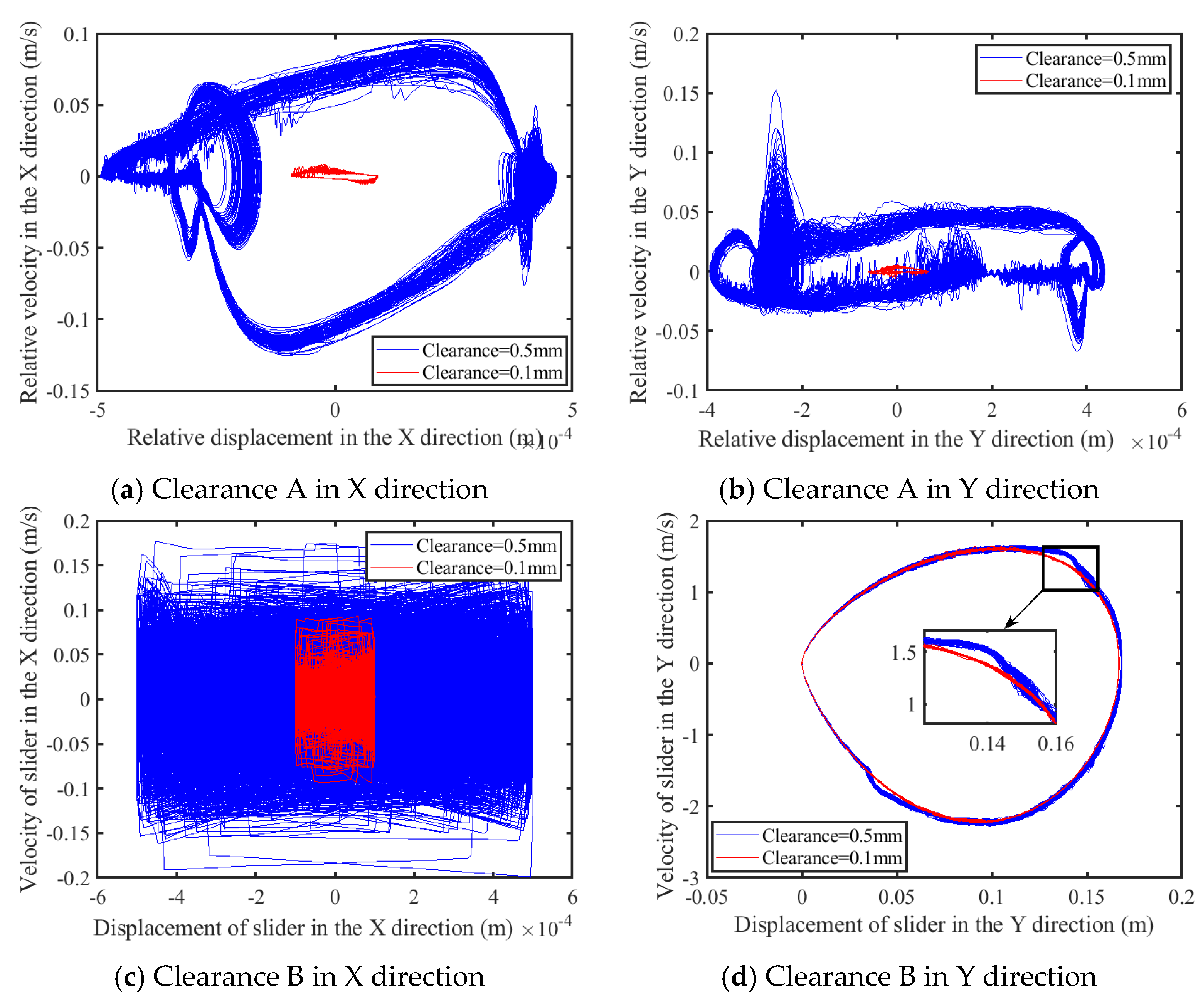
Different clearance magnitudes, specifically 0.1 mm and 0.5 mm, have been chosen to investigate the nonlinear attributes. To study the impact of clearance values in the range of 0.01–1 mm on nonlinear dynamics, a trend of the motion state at the clearance, changing with the clearance size, is constructed, depicting the variations as a function of the clearance dimension.
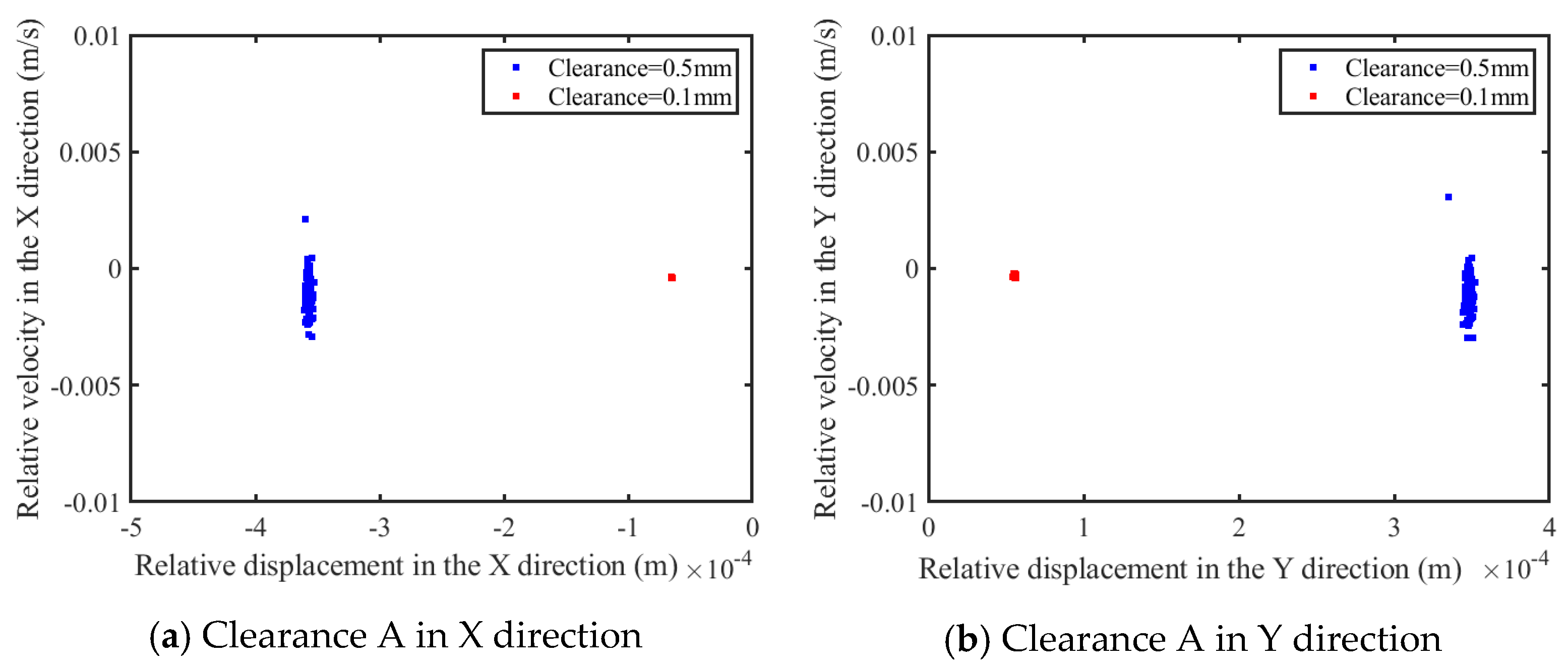
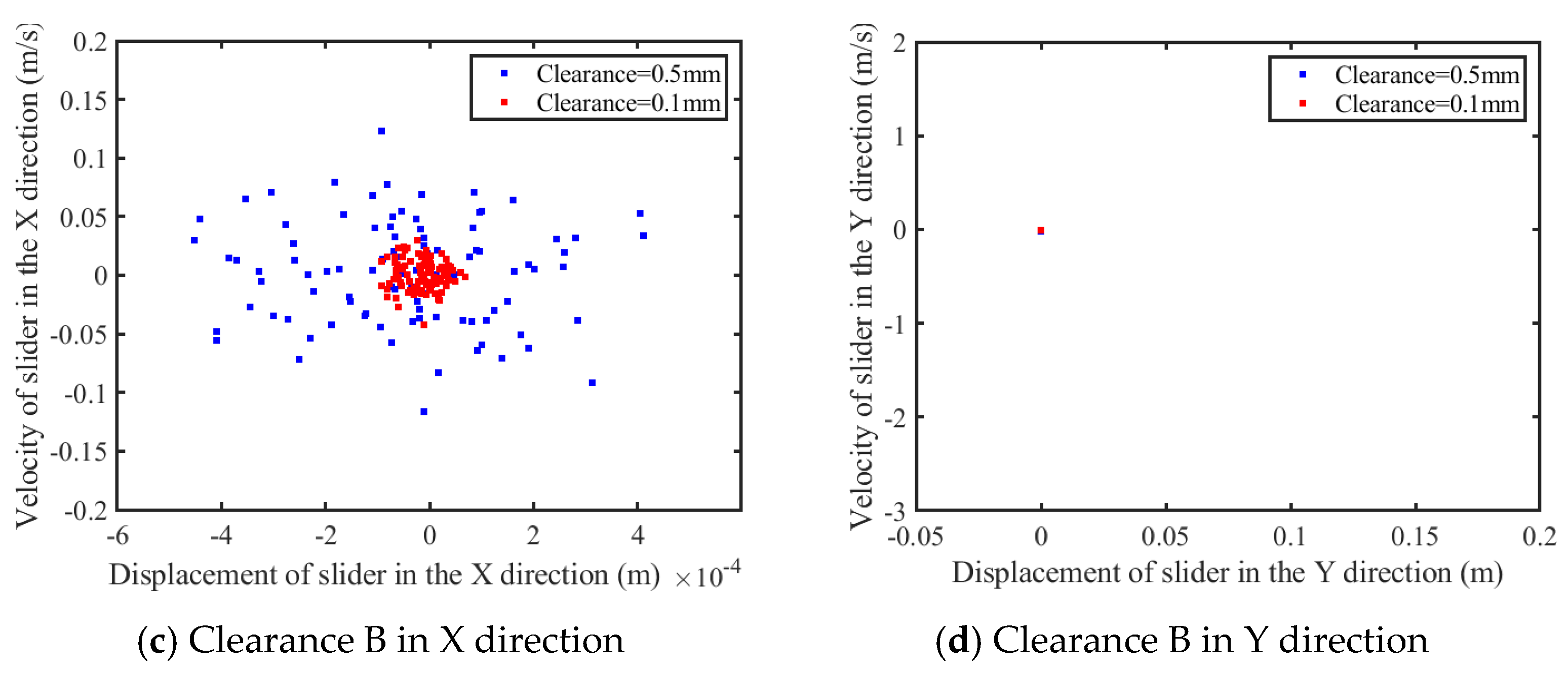
According to Figure 30a–c, as the clearance expands from 0.1 mm to 0.5 mm, the complexity of the phase diagram experiences intensification. However, according to Figure 30d, this amplification is less pronounced for the prismatic pair along the Y-axis, as evidenced by a detailed examination of the enlarged section. According to Figure 31a–c, for the increment of the clearance from 0.1 mm to 0.5 mm, there is a notable increase in the dispersal of the Poincaré mapping points associated with the revolute clearance and the prismatic clearance in the x-axis direction. According to Figure 31d, the Poincaré mapping points for the prismatic pair in the Y-axis direction remain as isolated points.
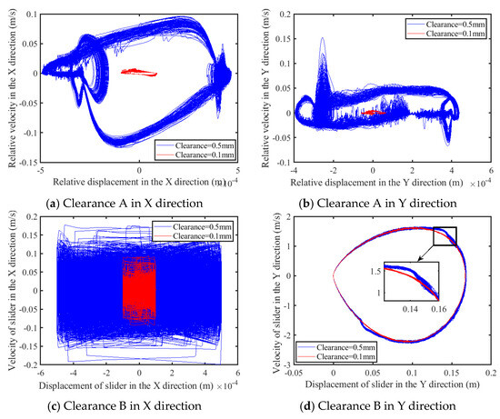
Figure 30.
Phase diagram of clearance.
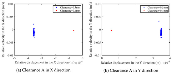
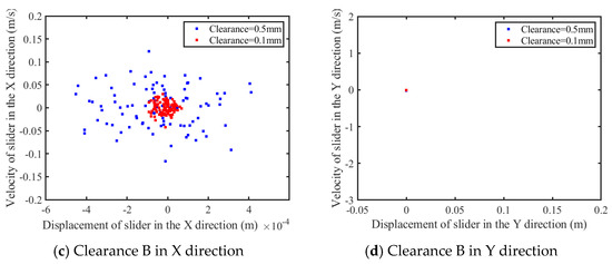
Figure 31.
Poincaré map of clearance.
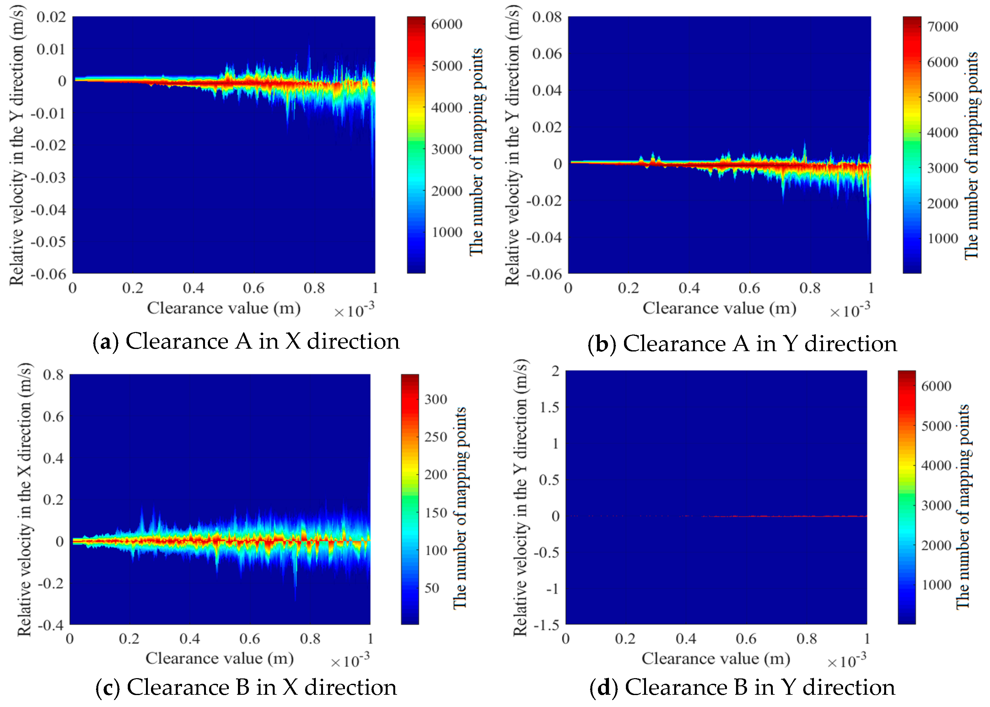
Figure 32 illustrates the changes in the trend of the motion state at the clearance with changes in the clearance size. The meanings of the colors in Figure 32 are as follows: Red indicates that the data points are more clustered. The transition from red to blue indicates that the data points are transitioning from clustered to sparse. An increase in the clearance value correlates with a rise in the instability of the motion state at the clearance. The chaotic behavior of prismatic pair B in the X direction is noticeably more pronounced than that of rotating pair A in both the X and Y directions. In the Y direction, the motion state of prismatic pair clearance B consistently exhibits a periodic movement. With the increase in clearance, the mechanism becomes more unstable.
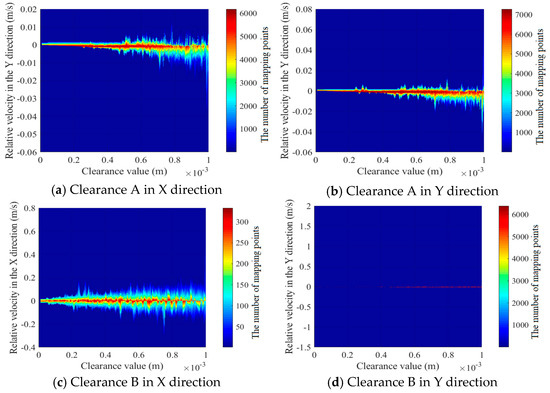
Figure 32.
The trend of the motion state at the clearance changing with clearance size.
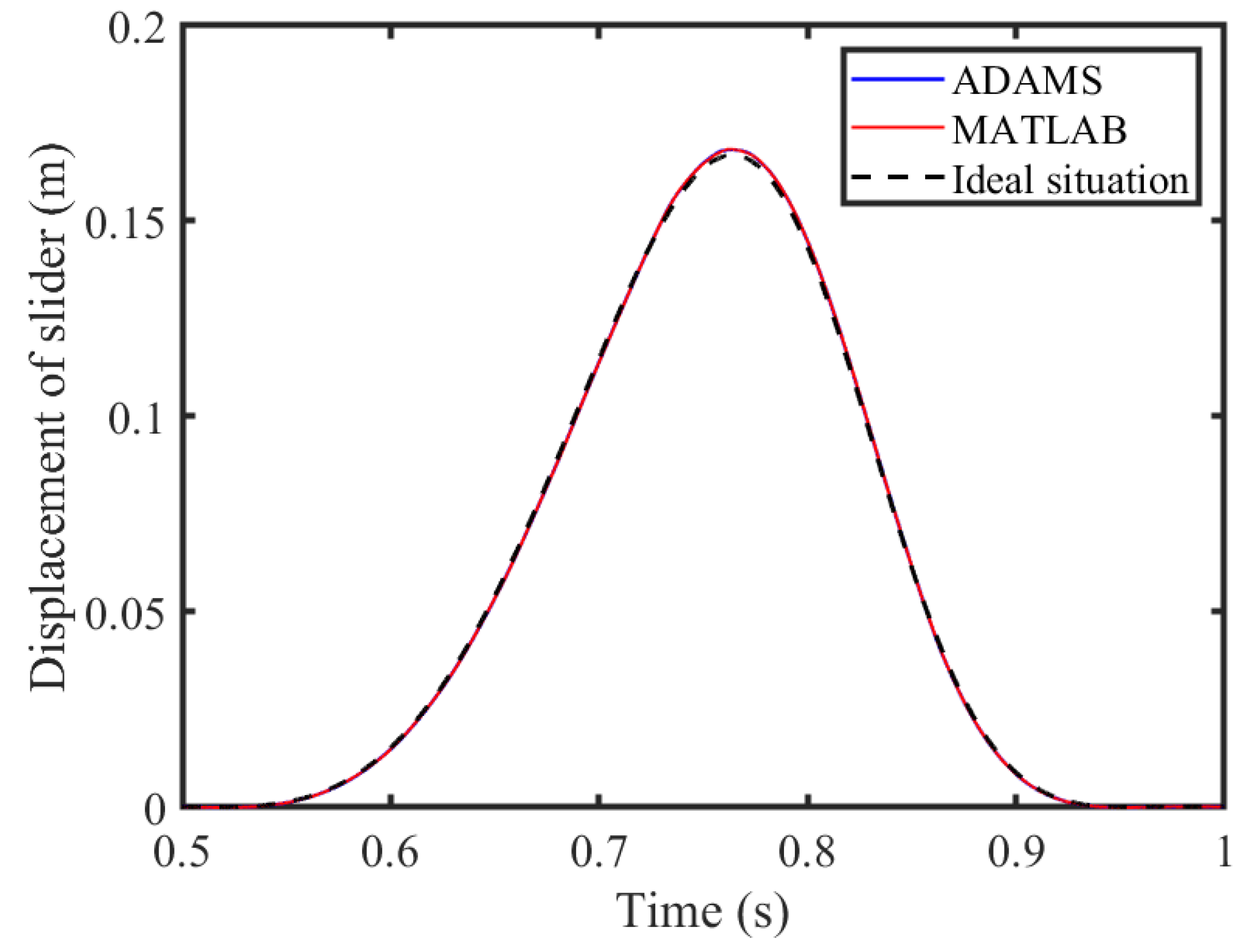
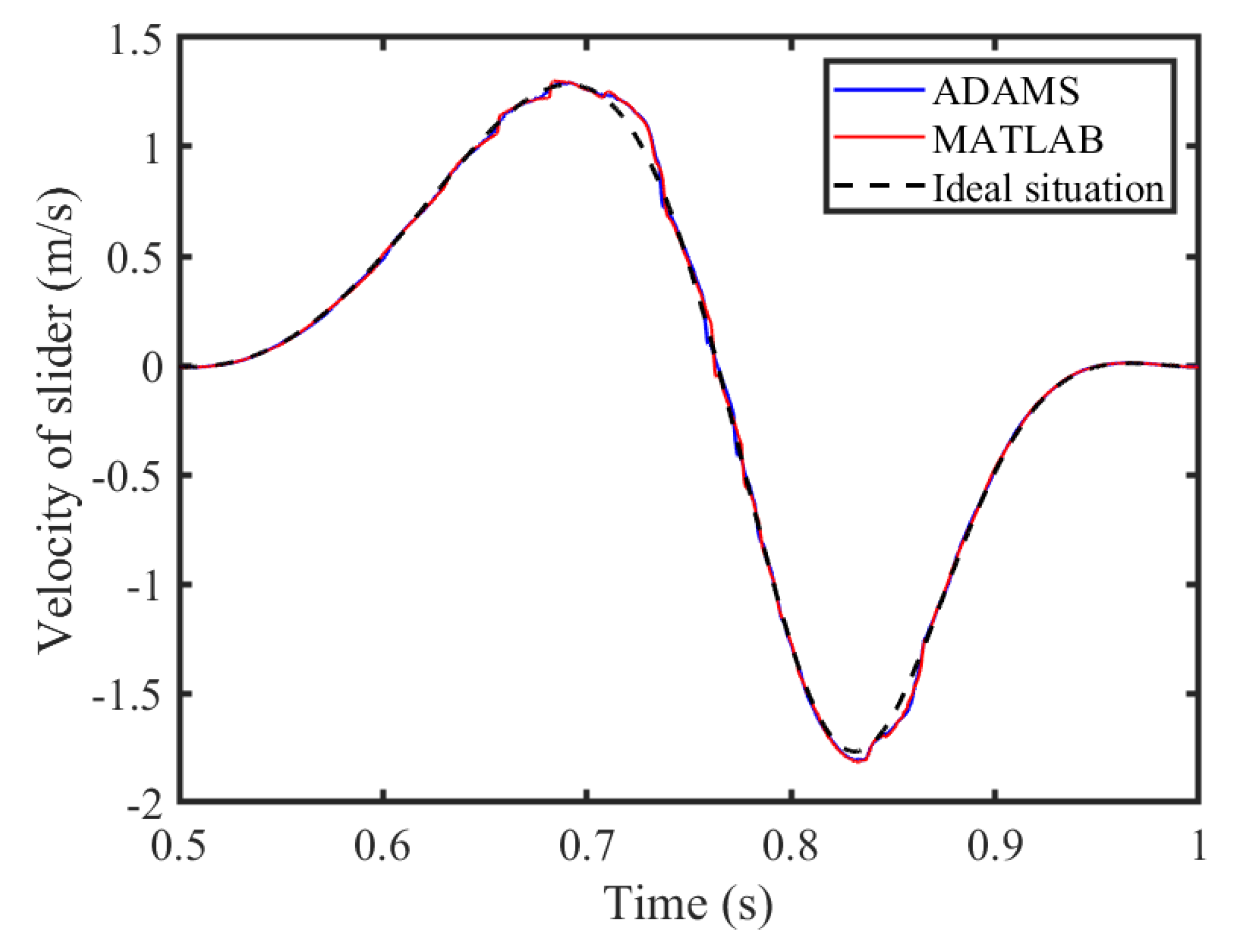
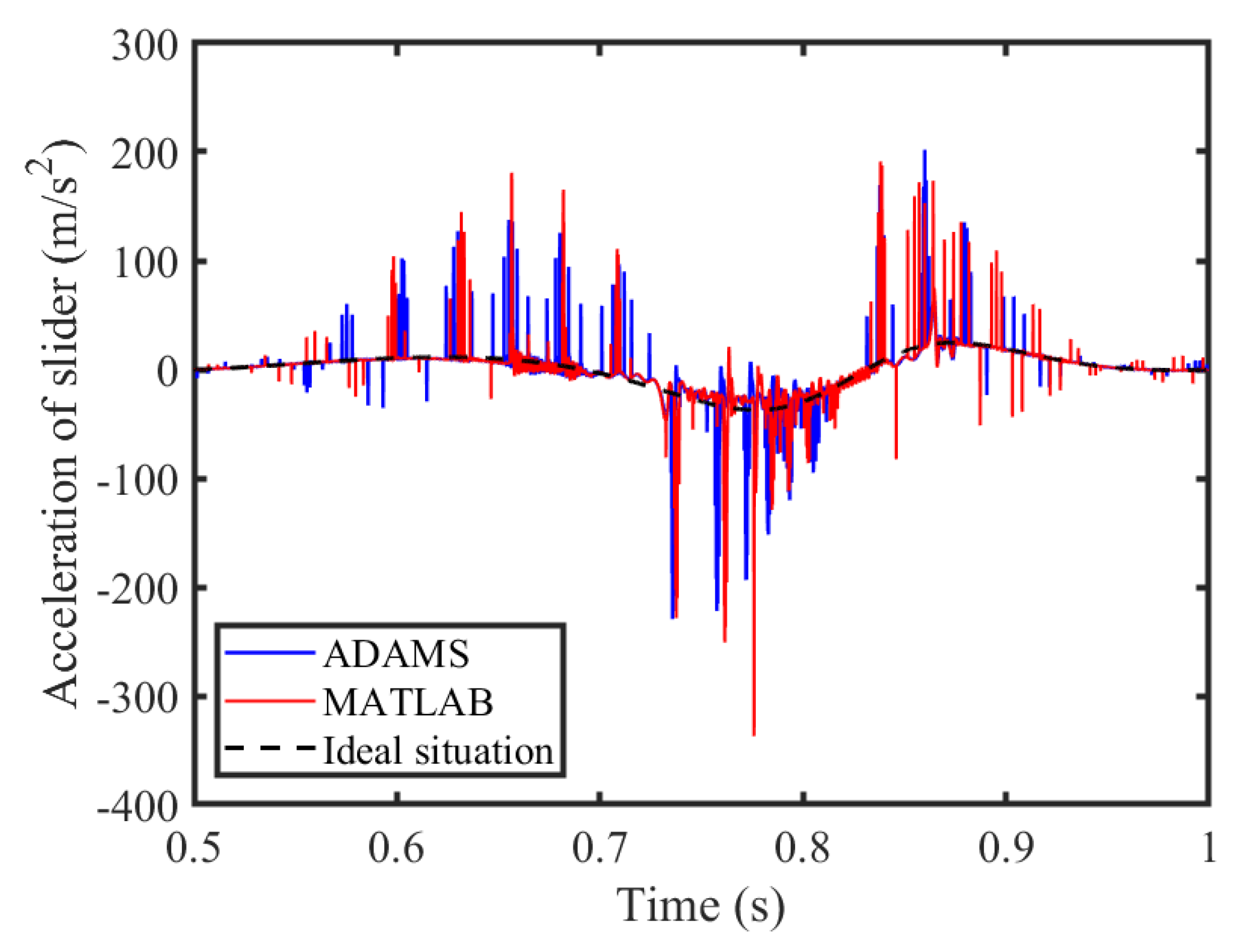
3.5. Virtual Prototype Simulation Verification
An ADAMS virtual prototype model of a six-bar mechanism with clearance is established herein to verify the correctness of the MATLAB (R2018b) results. The MATLAB results are compared and analyzed with the ADAMS simulation results. The displacement, velocity, and acceleration curves of the slider are shown in Figure 33, Figure 34 and Figure 35. Due to the low sensitivity of the displacement curve and velocity curve of the slider to the clearance, the curves are basically consistent in their trends and values, but there is a certain difference in the peak value of acceleration of the slider. The error is caused by differences in integration algorithms, contact collision detection strategies, differential equation forms, and other aspects. Therefore, has the potential to basically prove the correctness of the theoretical model.
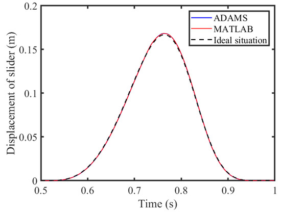
Figure 33.
Displacement of slider.
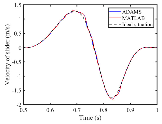
Figure 34.
Velocity of slider.

Figure 35.
Acceleration of slider.
4. Conclusions
This paper proposes a modeling method for the rigid–flexible coupling dynamic model of a planar multi-link mechanism considering the lubricated revolute clearance and prismatic clearance, and analyzes the dynamic response and nonlinear characteristics of the mechanism. The specific conclusions are as follows:
- (1)
- A dynamics model of a planar multi-link mechanism, considering the coupling effects of revolute lubrication clearance, the prismatic clearance pair, and the flexibility of the component, is built;
- (2)
- A comparative analysis is conducted on the effects of lubrication clearance and dry friction clearance on the dynamic response and nonlinear characteristics of a rigid–flexible coupled multi-link mechanism. Our research found that lubrication can reduce the peak dynamic response, improve the stability, and reduce the chaotic characteristics of the mechanism. Under the research parameters of this paper, after lubrication of the motion pair, the peak value of acceleration of the slider and the driving torque of the crank decreased by 35.93% and 73.10%, respectively;
- (3)
- The influences of different driving speeds, dynamic viscosities, and clearance sizes on the dynamic response and nonlinear characteristics of rigid–flexible coupling multi-link mechanisms with rotational lubrication clearance and prismatic clearance are discussed. When the driving speed increases from 30 rpm to 75 rpm, the peak value of acceleration of the slider and the driving torque of the crank increase by 84.18% and 64.62%, respectively. When the dynamic viscosity increases from 100 Cp to 500 Cp, the peak value of acceleration of the slider and the driving torque of the crank decrease by 23.68% and 65.65%, respectively. When the clearance value increases from 0.1 mm to 0.5 mm, the peak value of acceleration of the slider and the driving torque of the crank increase by 69.66% and 81.72%, respectively. Our research has found that, the higher the driving speed, the smaller the dynamic viscosity, the larger the clearance value, the greater the peak response of the mechanism, and the more obvious the chaos phenomenon;
- (4)
- The correctness of the theoretical model is verified through ADAMS virtual prototype simulation.
Author Contributions
Conceptualization, J.N. and S.J.; methodology, J.N.; software, K.M.; validation, M.A.; formal analysis, M.A.; investigation, J.N. and S.J.; resources, S.J.; data curation, K.M.; writing—original draft preparation, J.N.; writing—review and editing, J.N. and S.J.; visualization, K.M.; supervision, S.J.; project administration, J.N.; funding acquisition, S.J. All authors have read and agreed to the published version of the manuscript.
Funding
This research was funded by [Natural Science Foundation of Shandong Province] grant number [ZR2023QE039] and The APC was funded by [Jiang Shuai].
Data Availability Statement
Data used to support results of this research are included in this paper.
Conflicts of Interest
The authors declare that they have no conflicts of interest.
Appendix A
Shape function of flexible element is
where I is element matrix; , , ,, , l is length of flexible element.
Bending stiffness and axial stiffness of the unit is as follows:
where .
Constraint equation of RFC-mechanism with lubrication revolute clearance and prismatic pair clearance can be expressed as follows:
where ω is driving velocity of crank.
Table A1.
Geometric parameters.
Table A1.
Geometric parameters.
| Component | Length (m) | Centroid Position Length (m) | Mass (kg) | Moment of Inertia (10−3 kg·m2) |
|---|---|---|---|---|
| Crank 1 | 0.075 (L1) | 0.0375 (Ls1) | 0.751 (m1) | 1.408 (J1) |
| Rod 2 | 0.700 (L2) | 0.350 (Ls2) | 6.601 (m2) | 269.541 (J2) |
| Rod 3 | 0.584 (L3) | 0.292 (Ls3) | 5.515 (m3) | 156.744 (J3) |
| Rod 4 | 0.450 (L4) | 0.225 (Ls4) | 4.261 (m4) | 71.904 (J4) |
| Slider 5 | — | — | 5.776 (m5) | 4.813 (J5) |
Table A2.
Clearance and flexible member parameters.
Table A2.
Clearance and flexible member parameters.
| Parameter | Parameter Values |
|---|---|
| Length of slider (LT) | 150 mm |
| Width of slide (WT) | 100 mm |
| Thickness of slide (TT) | 50 mm |
| Bearing radius (R1) | 15 mm |
| Restitution coefficient (ce) | 0.9 |
| Poisson ratio (νm, νn) | 0.3 |
| Elastic modulus (Em, En) | 207 GPa |
| Friction coefficient (cf) | 0.15 |
| Young modulus (Ef) | 207 GPa |
| Cross section area (Af) | 0.06 × 0.02 m2 |
| Second moment of area (I) | 4 × 10⁻⁸ m4 |
| Density (ρ) | 7801 kg/m3 |
References
- Zhang, H.W.; Luo, Z.; Yao, S.B.; Xu, C.; Ji, H.; Li, L. Dynamic response and chaos analysis of a spatial multi-body system with multiple clearance joints and a flexible component. Commun. Nonlinear Sci. Numer. Simul. 2025, 145, 108699. [Google Scholar]
- Marques, F.; Flores, P.; Claro, J.P.; Lankarani, H.M. Modeling and analysis of friction including rolling effects in multibody dynamics: A review. Multibody Syst. Dyn. 2019, 45, 223–244. [Google Scholar]
- Chen, Z.N.; Qian, M.B.; Sun, F.X.; Pan, J.-X. A quantitative analysis method for contact force of mechanism with a clearance joint based on entropy weight and its application in a six-bar mechanism. Chin. Phys. B 2022, 31, 044501. [Google Scholar]
- Sungjoon, C.; Hwanjeong, C.; Dooyoul, L. Effect of Joint Clearance on Landing Gear Retraction Failure. Aerospace 2021, 8, 329. [Google Scholar] [CrossRef]
- Zhuang, X.C. Time-dependent kinematic reliability of a dual-axis driving mechanism for satellite antenna considering non-uniform planar revolute joint clearance. Acta Astronaut. 2022, 197, 91–106. [Google Scholar]
- Yang, M.J.; Jiang, M.; Xie, L.B.; Chen, Y. Influence of dynamic complexity on serial robots with joint clearance based on a nonlinearity measure. Proc. Inst. Mech. Eng. 2025, 239, 1575–1591. [Google Scholar]
- Zhang, F.; Yuan, Z. The Study of Coupling Dynamics Modeling and Characteristic Analysis for Flexible Robots with Nonlinear and Frictional Joints. Arab. J. Sci. Eng. 2022, 47, 15347–15363. [Google Scholar] [CrossRef]
- Yaqubi, S.; Dardel, M.; Daniali, H.M. Nonlinear dynamics and control of crank-slider mechanism with link flexibility and joint clearance. Proc. Inst. Mech. Eng. Part C-J. Mech. Eng. Sci. 2015, 230, 737–755. [Google Scholar]
- Jiang, S.; Chen, X. Test study and nonlinear dynamic analysis of planar multi-link mechanism with compound clearances. Eur. J. Mech. A Solids 2021, 88, 104260. [Google Scholar] [CrossRef]
- Zhang, X.; Kang, X.; Li, B. Development and investigation for rigid-flexible coupling dynamic performances of the morphing wing with clearance joints. Mech. Syst. Signal Process. 2025, 223, 111871. [Google Scholar] [CrossRef]
- Liang, D.; Song, Y.; Sun, T.; Jin, X. Rigid-flexible coupling dynamic modeling and investigation of a redundantly actuated parallel manipulator with multiple actuation modes. J. Sound Vib. 2017, 403, 129–151. [Google Scholar] [CrossRef]
- Chouaibi, Y.; Chebbi, A.H.; Affi, Z.; Romdhane, L. Precision comparison of two 3-DoF translational parallel manipulators based on the orientation errors due to joint clearances. Robotica 2022, 40, 3751–3767. [Google Scholar] [CrossRef]
- Chen, X.; Gao, S. Dynamic accuracy reliability modeling and analysis of planar multi-link mechanism with revolute clearances. Eur. J. Mech. A Solids 2021, 90, 104317. [Google Scholar] [CrossRef]
- Hou, Y.; Wang, Y.; Jing, G.; Deng, Y.; Zeng, D.; Qiu, X. Chaos phenomenon and stability analysis of RU-RPR parallel mechanism with clearance and friction. Adv. Mech. Eng. 2018, 10, 1687814017746253. [Google Scholar] [CrossRef]
- Tan, H.; Hu, Y.; Li, L. Effect of friction on the dynamic analysis of slider-crank mechanism with clearance joint. Int. J. Non-Linear Mech. 2019, 115, 20–40. [Google Scholar] [CrossRef]
- Meng, F.; Wu, S.; Zhang, F.; Zhang, Z.; Hu, J.; Li, X. Modeling and Simulation of Flexible Transmission Mechanism with Multiclearance Joints for Ultrahigh Voltage Circuit Breakers. Shock Vib. 2015, 2015, 392328. [Google Scholar] [CrossRef]
- Erkaya, S. Investigation of joint clearance effects on actuator power consumption in mechanical systems. Measurement 2019, 134, 400–411. [Google Scholar] [CrossRef]
- Marques, F.; Isaac, F.; Dourado, N.; Flores, P. An enhanced formulation to model spatial revolute joints with radial and axial clearances. Mech. Mach. Theory 2017, 116, 123–144. [Google Scholar] [CrossRef]
- Xiang, W.; Yan, S. Dynamic analysis of space robot manipulator considering clearance joint and parameter uncertainty: Modeling, analysis and quantification. Acta Astronaut. 2020, 169, 158–169. [Google Scholar] [CrossRef]
- Bai, Z.; Zhao, J. A Study on Dynamic Characteristics of Satellite Antenna System considering 3D Revolute Clearance Joint. Int. J. Aerosp. Eng. 2020, 2020, 1–15. [Google Scholar] [CrossRef]
- Li, B.; Wang, S.-M.; Gantes, C.J.; Tan, U.-X. Nonlinear dynamic characteristics and control of planar linear array deployable structures consisting of scissor-like elements with revolute clearance joint. Adv. Struct. Eng. 2020, 24, 1369433220971728. [Google Scholar] [CrossRef]
- Chen, Y.; Wu, X.; Wu, K.; Sun, Y.; Yu, C.; Xia, X. An experimental and analytical study on dynamic behaviors of high-precision mechanism including revolute clearance joints. J. Braz. Soc. Mech. Sci. Eng. 2022, 44, 120. [Google Scholar] [CrossRef]
- Chen, X.; Jiang, S. Dynamic response and chaos in planar multi-link mechanism considering revolute clearances. Arch. Appl. Mech. 2020, 90, 1919–1941. [Google Scholar] [CrossRef]
- Yuan, W.; Liu, J.; Ning, F.P. Dynamic analysis of crank slider mechanism considering 3D translational joint clearance based on variable contact area. Mech. Ind. 2025, 26, 5. [Google Scholar]
- Wu, X.; Sun, Y.; Wang, Y.; Chen, Y. Dynamic analysis of the double crank mechanism with a 3D translational clearance joint employing a variable stiffness contact force model. Nonlinear Dyn. 2019, 99, 1937–1958. [Google Scholar] [CrossRef]
- Flores, P.; Leine, R.; Glocker, C. Modeling and analysis of planar rigid multibody systems with translational clearance joints based on the non-smooth dynamics approach. Multibody Syst. Dyn. 2010, 23, 165–190. [Google Scholar] [CrossRef]
- Qian, M.; Qin, Z.; Yan, S.; Zhang, L. A comprehensive method for the contact detection of a translational clearance joint and dynamic response after its application in a crank-slider mechanism. Mech. Mach. Theory 2020, 145, 103717. [Google Scholar] [CrossRef]
- Wei, Z.; Wang, Z.Y.; Li, D.D.; Liang, D. Rigid-flexible coupling dynamic modelling and dynamic accuracy analysis of planar cam four-bar mechanism with multiple clearance joints. Proc. Inst. Mech. Eng. Part K J. Multi-Body Dyn. 2024, 238, 421–444. [Google Scholar]
- Chen, Z.; Qian, L. Nonlinear dynamic characteristics analysis of planar flexible rotating beams with clearance joint. J. Braz. Soc. Mech. Sci. Eng. 2020, 42, 333. [Google Scholar] [CrossRef]
- Sun, D.; Zhang, B.; Liang, X.; Shi, Y.; Suo, B. Dynamic analysis of a simplified flexible manipulator with interval joint clearances and random material properties. Nonlinear Dyn. 2019, 98, 1049–1063. [Google Scholar] [CrossRef]
- Wan, Q.; Liu, G.; Shi, H.; Zhang, X.; Ning, X. Analysis of dynamic characteristics for momentum wheel assembly with joint clearance. Adv. Mech. Eng. 2018, 10, 1–12. [Google Scholar] [CrossRef]
- Chen, Z.-Q.; Qian, L.-F.; Chen, G.-S.; Nie, S.-C.; Yin, Q.; Yue, C.-C. Dynamics of luffing motion of a hydraulically driven shell manipulator with revolute clearance joints. Def. Technol. 2021, 18, 689–708. [Google Scholar]
- Bai, Z.F.; Ning, Z.Y.; Zhou, J.S. Study on Wear Characteristics of Revolute Clearance Joints in Mechanical Systems. Micromachines 2022, 13, 1018. [Google Scholar] [CrossRef]
- Xu, L.; Han, Y.; Dong, Q.; Jia, H.L. An approach for modelling a clearance revolute joint with a constantly updating wear profile in a multibody system: Simulation and experiment. Multibody Syst. Dyn. 2019, 45, 457–478. [Google Scholar] [CrossRef]
- Li, S.H.; Han, X.Y.; Wang, J.Q.; Sun, J.; Li, F.J. Contact Model of Revolute Joint with Clearance Based on Fractal Theory. Chin. J. Mech. Eng. 2018, 31, 109. [Google Scholar]
- Li, Y.; Yang, Y.; Li, M.; Liu, Y.; Huang, Y. Dynamics analysis and wear prediction of rigid-flexible coupling deployable solar array system with clearance joints considering solid lubrication. Mech. Syst. Signal Process. 2022, 162, 108059. [Google Scholar] [CrossRef]
- Alshaer, B.J.; Nagarajan, H.; Beheshti, H.K.; Lankarani, H.M.; Shivaswamy, S. Dynamics of a Multibody Mechanical System With Lubricated Long Journal Bearings. J. Mech. Des. 2005, 127, 493–498. [Google Scholar] [CrossRef]
- Askari, E.; Flores, P. Coupling multi-body dynamics and fluid dynamics to model lubricated spherical joints. Arch. Appl. Mech. 2020, 90, 2091–2111. [Google Scholar] [CrossRef]
- Gao, S.; Fan, S.W.; Wang, W.J. The research on the failure mechanism and dynamic reliability of lubricated clearance. Proc. Inst. Mech. Eng. 2024, 238, 9248–9263. [Google Scholar] [CrossRef]
- Tian, Q.; Zhang, Y.; Chen, L.; Flores, P. Dynamics of spatial flexible multibody systems with clearance and lubricated spherical joints. Comput. Struct. 2009, 87, 913–929. [Google Scholar] [CrossRef]
- Zhang, T.; Liu, G.; Wang, X.; Ma, S. Dynamic analysis of planar multibody system with a lubricated revolute clearance joint using an improved transition force model. Adv. Mech. Eng. 2017, 9, 168781401774408. [Google Scholar]
- Flores, P.; Lankarani, H.M. Spatial rigid-multibody systems with lubricated spherical clearance joints: Modeling and simulation. Nonlinear Dyn. 2010, 60, 99–114. [Google Scholar] [CrossRef]
- Tian, Q.; Lou, J.; Mikkola, A. A new elastohydrodynamic lubricated spherical joint model for rigid-flexible multibody dynamics. Mech. Mach. Theory 2017, 107, 210–228. [Google Scholar] [CrossRef]
- Chen, X.; Wang, T.; Jiang, S. Study on dynamic behavior of planar multibody system with multiple lubrication clearance joints. Eur. J. Mech. A Solids 2022, 91, 104404. [Google Scholar] [CrossRef]
- Chen, X.; Jiang, S.; Wang, T. Dynamic modeling and analysis of multi-link mechanism considering lubrication clearance and flexible components. Nonlinear Dyn. 2022, 107, 3365–3383. [Google Scholar] [CrossRef]
- Flores, P.; Ambrósio, J.; Claro, J.C.P.; Lankarani, H.M. Translational Joints with Clearance in Rigid Multibody Systems. J. Comput. Nonlinear Dyn. 2008, 3, 112–113. [Google Scholar] [CrossRef]
- Chen, X.; Jiang, S.; Deng, Y. Dynamic Responses of Planar Multilink Mechanism considering Mixed Clearances. Shock Vib. 2020, 2020, 8725845. [Google Scholar] [CrossRef]
- Flores, P.; Ambrósio, J.; Claro, J.P. Dynamic Analysis for Planar Multibody Mechanical Systems with Lubricated Joints. Multibody Syst. Dyn. 2004, 12, 47–74. [Google Scholar] [CrossRef]
- Zheng, E.; Wang, T.; Guo, J.; Zhu, Y.; Lin, X.; Wang, Y.; Kang, M. Dynamic modeling and error analysis of planar flexible multilink mechanism with clearance and spindle-bearing structure. Mech. Mach. Theory 2019, 131, 234–260. [Google Scholar] [CrossRef]
- Baumgarte, J. Stabilization of constraints and integrals of motion in dynamical systems. Comput. Methods Appl. Mech. Eng. 1972, 1, 1–16. [Google Scholar] [CrossRef]


Disclaimer/Publisher’s Note: The statements, opinions and data contained in all publications are solely those of the individual author(s) and contributor(s) and not of MDPI and/or the editor(s). MDPI and/or the editor(s) disclaim responsibility for any injury to people or property resulting from any ideas, methods, instructions or products referred to in the content. |
© 2025 by the authors. Licensee MDPI, Basel, Switzerland. This article is an open access article distributed under the terms and conditions of the Creative Commons Attribution (CC BY) license (https://creativecommons.org/licenses/by/4.0/).