Article

Tribo-Dynamic Behavior of Double-Row Cylindrical Roller Bearings Under Raceway Defects and Cage Fracture

1
Science Research Center, National Innovation Center of High-Speed Train, Qingdao 266111, China
2
Key Laboratory of Traffic Safety on Track of Ministry of Education, School of Traffic & Transportation Engineering, Central South University, Changsha 410075, China
3
Joint International Research Laboratory of Key Technology for Rail Traffic Safety, Changsha 410075, China
4
National & Local Joint Engineering Research Center of Safety Technology for Rail Vehicle, Changsha 410075, China
*
Author to whom correspondence should be addressed.
Lubricants 2025, 13(2), 80; https://doi.org/10.3390/lubricants13020080
Submission received: 14 December 2024 / Revised: 30 January 2025 / Accepted: 10 February 2025 / Published: 11 February 2025

Abstract

High-quality data samples are essential for the early detection of bearing failures and the analysis of bearing behavior. The accurate simulation of bearing fault conditions can provide valuable insights into understanding failure mechanisms. This paper establishes a new numerical simulation method for double-row cylindrical roller bearing (DCRB) faults based on the augmented Lagrange dynamics method, overcoming the limitations of previous models by incorporating fault conditions related to cage fracture. This method accounts for the dynamic behavior of the rollers during the motion cycle and their interactions with other DCRB components. By comparing the characteristic frequencies of the fault components, the model not only replicates the dynamic behavior of faulty DCRBs more accurately but also offers a deeper understanding of fault-induced dynamics. This advancement provides a more comprehensive and realistic tool for bearing fault analysis.

1. Introduction

High-speed trains, a crucial mode of transportation, have significantly improved people’s daily lives. Therefore, ensuring their safety, stability, and comfort is of utmost importance. The double-row cylindrical roller bearing (DCRB), as a critical rotating component, operates under continuous high-load and high-speed conditions, resulting in complex and variable contact and friction interactions among bearing components. This ultimately leads to various forms of bearing failure. This study aims to simulate multiple bearing faults and replicate the actual operational behavior of faulty bearings to provide sufficient data for subsequent research.
In recent years, there have been numerous innovations and studies on bearing failure modes. Xu et al. [1] investigated the interaction between raceway defects and bearing misalignment, as well as the dynamic interaction between gears and bearings. Tingarikar et al. [2] examined the vibrations induced by raceway waviness in bearings subjected to external loading. Patel et al. [3] established a mathematical model for cylindrical roller bearings (CRB) to analyze the interaction between race and roller defects, aiming to characterize the behavior of bearings under variable speed working conditions. Liu et al. [4] enhanced their model by developing methods for defect propagation and morphology modeling. Tu et al. [5] proposed a dynamic model to analyze the bearings’ vibration response in skidding scenarios. Chen et al. [6] investigated the impact of wear on the lubrication performance of hydrodynamic bearings and the associated vibration signatures for fault diagnosis. The authors developed a finite element model of a two-disk rotor supported by worn bearings, demonstrating that wear significantly alters bearing characteristics and system critical speeds, with vibration signatures in the y-direction being more sensitive to wear than in the x-direction. Ebrahim et al. [7] investigated the effects of wear-induced geometric imperfections in tilting pad journal bearings (TPJBs) on system dynamics, integrating a mixed elastohydrodynamic model with thermal and dynamic models to assess the impact of bearing wear on rotor-TPJB behavior. Wu et al. [8] developed a rotor-bearing system model, integrating the oil churning effect and time-varying excitations caused by localized bearing faults. Li et al. [9] analyzed how vibration excitation affects the dynamic behavior of bearings, focusing on acceleration, displacement, and stiffness under various conditions. Peng et al. [10] investigated the failure modes and fault diagnosis of wind turbine bearings, focusing on methods such as spectrum analysis, wavelet analysis, and artificial intelligence for fault detection, and also explored the challenges and future directions in wind turbine bearing failure analysis. Xu et al. [11] proposed a dynamic model for double-row cylindrical roller bearings with irregular-shaped defects, highlighting the significant impact of defect geometry on bearing vibrations and performance, and demonstrating that simplified defect models tend to overestimate vibration characteristics compared to models incorporating actual defect shapes. Shinde et al. [12] built on the foundation of advanced fault diagnosis techniques, such as the combined use of the matrix method of dimensional analysis (MMDA) and support vector machine (SVM) for detecting unbalance and misalignment in rotor-bearing systems to further explore the complex dynamics and fault characteristics of bearings under high-speed conditions.
The failure modes of bearing cages have become a hot topic in recent years, with significant research efforts dedicated to this area. Zhao et al. [13] proposed a tribo-dynamic model for cryogenic solid-lubricated ball bearings (CSLBBs) in liquid rocket engines, incorporating solid-lubricated traction, six-DOF ball motion, and ball-cage contact collisions. Deng et al. [14] presented a dynamic model that incorporating cage dynamics and elastohydrodynamic lubrication, highlighting optimal structural size alignment to improve the stability and vibration behavior of ball bearings. Denni et al. [15] proposed a dynamic model for the bearings that includes the vertical damping of the oil film present in the contact interface between the roller and the cage, enabling a precise estimation of the forces acting on the cage. Wang et al. [16] developed a nonlinear model to study the dynamic behavior of fractured cages and misalignment in rolling bearings. Li et al. [17] developed a model of ball bearings incorporating a flexible cage to account for the wear-induced reduction in the cage pocket. Shi et al. [18] developed a dynamic model for planet roller bearings that accounts for the impact of cage cracks. Luo et al. [19] investigated the effect of cage slip and friction force on vibration responses using a nonlinear dynamic model. In conclusion, while previous models have focused on simplified defect representations, they often fail to accurately capture the complex dynamics induced by cage fractures in double-row cylindrical roller bearings. This study introduces a novel numerical simulation method based on the augmented Lagrange dynamics approach, which overcomes these limitations by incorporating cage fracture and accounting for the dynamic behavior of rollers and their interactions with other bearing components. This advancement offers a more realistic and comprehensive tool for bearing fault analysis.

2. Mathematical Modeling for Defective DCRBs

This study models a bearing of type NJ(P)3226X1 (CRRC Qingdao Sifang Co., Ltd., Qingdao, China; Harbin Bearing Group Co., Ltd., Harbin, China; Wafangdian Bearing Group Corporation, Wafangdian, China; Luoyang Bearing Group Co., Ltd., Luoyang, China; and Nanjing Puzhen NTM Railway Bearing Co., Ltd., Nanjing, China), as shown in Figure 1. Two coordinate systems are defined for the multibody system: the global coordinate system XOY and the body-fixed coordinate system xioiyi, which are attached to the center of mass of each object. Figure 2 illustrates the multibody system of a double-row cylindrical bearing. The global coordinate XOY is positioned at the center of the bearing housing, while each object’s center of mass defines its own body-fixed coordinate system xioiyi. The angle of rotation of xioiyi relative to XOY is φ i . The gravitational force acting on each component is Gi, and the inner ring is subjected to an external force Q and rotational drive ω I .

2.1. Modeling for Defects of DCRB

2.1.1. Modeling for Localized Defect on Inner Raceway

Figure 3 illustrates the schematic illustration of the contact between roller i and inner raceway. The defect on the raceway is characterized as a rectangular notch with a width b and a depth h. The relative motion between the roller and the inner raceway causes contact interactions. The relative displacement of roller i with respect to the inner ring is defined as u B i , which can be derived from the displacement relationships between the roller and the inner raceway.
u B i = u R i u I
where u R i and u I are the global position vector of roller i and inner ring, respectively. Then, deformation depth δ I i is derived
δ I i = r I + r R u B i
where r I and r R are the radii of the inner raceway and the roller, respectively.
As illustrated in Figure 3a, n 1 is the normal vector in the contact direction between roller i and the inner raceway, while t 1 is the corresponding tangential vector. These vectors can be calculated from the relative displacement between roller i and the inner ring.
n 1 = u B i u B i
This study employs the Johnson nonlinear contact model [20], which is suitable for the contact between two cylinders, to compute the interaction forces between the roller and the raceway. The equation is as follows:
δ = F n π E L ln 4 π E Δ R L F n 1
where δ is the penetration depth of the contact, F n is the corresponding contact force, and E is the effective elastic modulus of the two cylinders, expressed as shown in Equation (5). L is the effective contact length between the two cylinders, and Δ R = R i ± R j , where the sign is positive for external contact and negative for internal contact. R i / j are the curvatures of cylinders i and j, respectively. For the contact between the inner raceway and roller i, the deformation depth is δ = δ I i , and the contact force is F n = F I n i . The contact length is the length of the roller, L = l r , and the contact radius Δ R = r I + r R . For the contact situations discussed later, Δ R = r O r R corresponds to the interaction between the outer raceway and the roller, and Δ R = 2 r R corresponds to the contact between two rollers.
1 E = 1 ν i 2 E i + 1 ν j 2 E j
where ν i / j and E i / j are the Poisson’s ratios and contact stiffness of bodies i and j, respectively.
Subsequently, the corresponding friction force is calculated by the LuGre friction model [21], which simulates the deformation of bristles. This model accurately represents the viscous effects at low relative sliding velocities and the process of transitioning between sliding and stick–slip behavior. The formula is as follows:
F t = σ 0 z + σ 1 z ˙ + σ 2 v t F n
z ˙ = d z d t = v t σ 0 v t μ k + μ s μ k e v t v s γ 1   z
where σ 0 , σ 1 , and σ 2 are the stiffness coefficient, damping coefficient, and viscous friction coefficient, respectively. μ s and μ k are the static and kinetic friction coefficients, respectively. v t and v s represent the relative sliding velocity and the Stribeck velocity [21]. In this case, we take σ 0 = 1 e 5   N / m [22], σ 1 = 400   N s / m [23], and since this is dry friction contact, we take σ 2 = 0 [21], γ 1 = 2 [24] represents a temporal characteristic of the rising static friction.
Figure 3b illustrates the defect in the inner raceway. When the roller enters the defect region, the contact depth between the roller and the raceway no longer applies to the previous calculation formula. Therefore, a new calculation is required to determine the contact relationship between the roller and the raceway. The formula for the calculation is given as follows:
d ϕ i 1 = m i n h 1 , r I 1 cos α i + r R r R 2 r I 2 sin 2 α i ϕ i 1 ϕ f 1 ± 0.5 Δ ϕ f 1 0 o t h e r s
where ϕ i 1 represents the azimuth angle of roller i in the global coordinate system XOY, and α i is the angle between roller i and the edge of the defect. For the inner raceway defect, the defect region rotates together with the inner race. Therefore, in the global coordinate system XOY, the actual azimuth angle of the defect center is expressed as ϕ f 1 = ϕ f 1 + φ 2 , where Δ ϕ f 1 = b 1 / r I represents the angular range of the defect region on the inner race.
α i = ϕ i 1 ϕ f 1 + 0.5 Δ ϕ f 1 ϕ i 1 ϕ f 1 0.5 Δ ϕ f 1 , ϕ f 1 ϕ f 1 + 0.5 Δ ϕ f 1 ϕ i 1 ϕ i 1 ϕ f 1 , ϕ f 1 + 0.5 Δ ϕ f 1
sin ϕ i 1 = u B i 2 / u B i cos ϕ i 1 = u B i 1 / u B i
The total force exerted by all nr rollers on the inner race can be obtained by summing the forces applied by each roller on the inner race. This gives the total force on the inner race in the global coordinate system XOY, which is the resultant force from the rollers.
F I X F I Y = i = 1 n r sin ϕ i 1 cos ϕ i 1 cos ϕ i 1 sin ϕ i 1 F I t i F I n i
where F I t i and F I n i represent the contact force and frictional force exerted by roller i on the inner race, respectively.

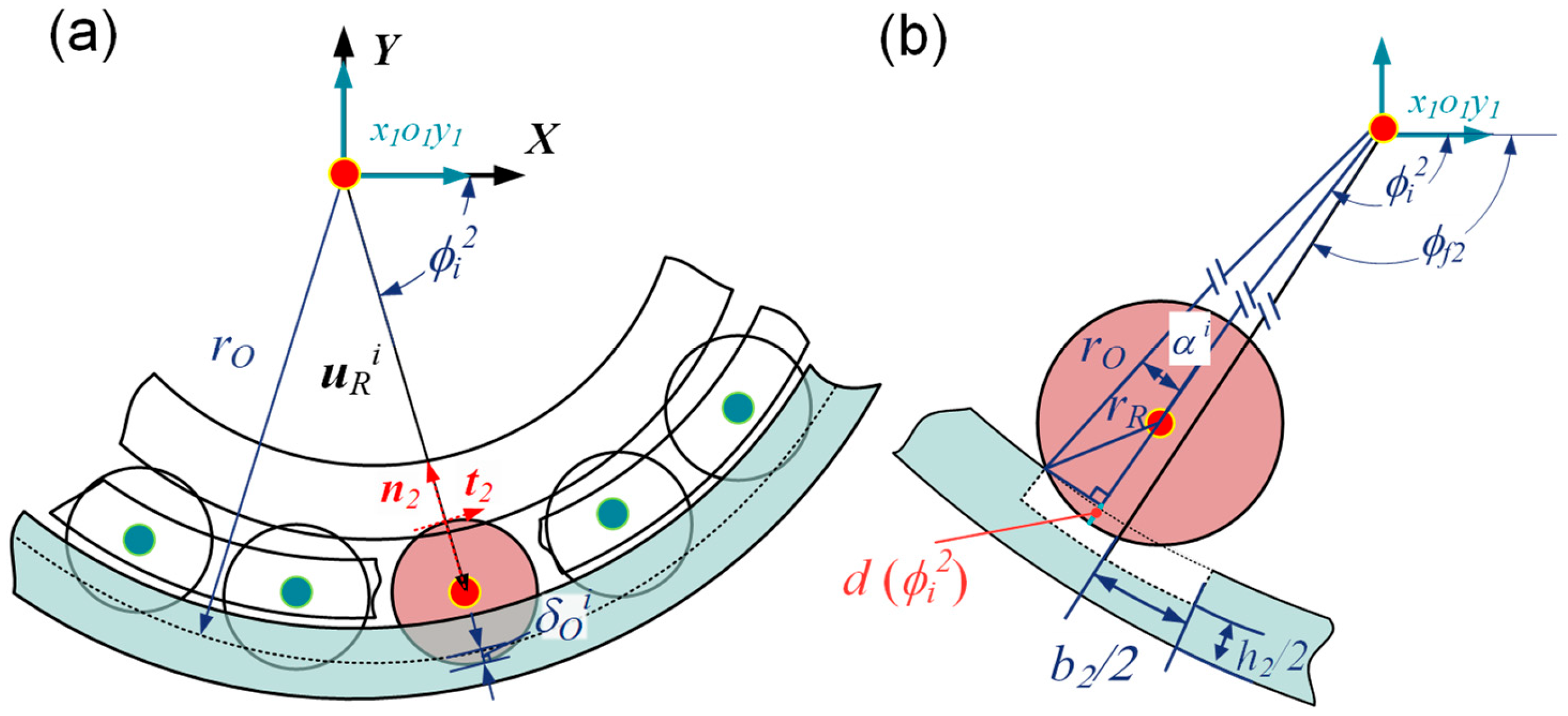
2.1.2. Modeling for Localized Defect on Outer Raceway

Figure 4 shows a schematic illustration of the contact situation between the roller and the outer race. Figure 4a presents the contact situation between roller i and the outer race, and the formula for calculating the contact deformation depth is as follows:
δ O i = u R i + r R r O
where r O is the radius of the outer ring.
The normal vector of the contact between roller i and the outer race is represented as follows:
n 2 = u R i u R i
Similarly, the interaction force and frictional force between roller i and the outer race are calculated using Equations (4) and (6), with the directions being n 2 and t 2 , respectively. When the roller enters the defect region of the outer race, the new contact depth calculation formula is as follows:
d ϕ i 2 = m i n h 2 , r O cos α i 1 + r R + r R 2 r O 2 sin 2 α i ϕ i 2 ϕ f 2 ± 0.5 Δ ϕ f 2 0 o t h e r s
The angular range of the outer raceway defect is Δ ϕ f 2 = b 2 / r O , where ϕ f 2 represents the azimuth angle of the center of the outer raceway defect in the global coordinate system XOY. Unlike the inner race, the outer race does not rotate. α i denotes the angle between the center azimuth angle of roller i and the boundary edge of the outer race defect, calculated as follows:
α i = ϕ i 2 ϕ f 2 + 0.5 Δ ϕ f 2 ϕ i 2 ϕ f 2 0.5 Δ ϕ f 2 , ϕ f 2 ϕ f 2 + 0.5 Δ ϕ f 2 ϕ i 2 ϕ i 2 ϕ f 2 , ϕ f 2 + 0.5 Δ ϕ f 2
sin ϕ i 2 = u R i 2 / u R i cos ϕ i 2 = u R i 1 / u R i
The sum of the forces exerted by all the rollers on the outer race is represented as follows:
F O X F O Y = i = 1 n r sin ϕ i 2 cos ϕ i 2 cos ϕ i 2 sin ϕ i 2 F O t i F O n i
where F O t i and F O n i are the contact force and frictional force exerted by roller i on the outer race, respectively.

2.1.3. Modeling for Cage Fracture

The cage pillar fracture is a prevalent type of fault in bearing cages. This study simulates a scenario involving a missing cage separator. Numerous potential causes for this fault can arise in actual train operations, including, but not limited to, misaligned loads, insufficient lubrication, and excessive loading conditions. Figure 5 presents a schematic representation of a broken cage separator fault. It is evident that this fault permits two adjacent rollers, designated as roller i and roller j, to move freely within the pocket of the missing separator. This scenario not only causes them to collide with each other, but also results in more severe impacts with the intact side of the cage pillar.
For roller j, in addition to the contact with the inner and outer raceways, it also makes contact with roller i and the right-side cage wall. Therefore, additional unit vectors are required to describe the direction of these contacts. The contact normal and tangential vectors between roller j and roller i on the left side are defined as n l j and t l j , respectively. The contact normal and tangential vectors between roller j and the right-side cage wall are defined as n r j and t r j , respectively. The normal and tangential vectors for the contact between roller j and the raceways, denoted as n j and t j , are modeled in the same way as for raceway faults.
t l j = sin ϕ j Δ ϕ R , cos ϕ j Δ ϕ R T n l j = cos ϕ j Δ ϕ R , sin ϕ j Δ ϕ R T t r j = sin ϕ j + Δ ϕ R , cos ϕ j + Δ ϕ R T n r j = cos ϕ j + Δ ϕ R , sin ϕ j + Δ ϕ R T
Figure 5a shows a schematic of the contact between two rollers. For the contact between roller i and roller j, the deformation depth and relative rotational velocity are expressed as follows:
δ R i j = 2 r R u R j u R i   u R R i j = u ˙ R i · n r i u ˙ R j · n l j + ω r i + ω r j r R
where u ˙ R i and u ˙ R j represent the translational velocity vectors of rollers i and j, respectively, while ω r i and ω r j denote their rotational velocities. Based on δ R i j , the right-side contact force F R R n i and friction force F R R t i for roller i, as well as the left-side contact force F R L n j and friction force F R L t j for roller j, can be determined. The calculations of the contact forces and friction forces are consistent with the models introduced in the section on raceway defects.
Figure 5b shows a schematic illustration of the contact between a roller and both sides of the cage wall. Due to the absence of the cage pillar, the roller can no longer be fixed in its original position, and the assumption of an ideal revolute joint connection between the roller and the cage is no longer valid. Therefore, the contact between the roller and the intact cage wall on the opposite side must also be considered. Taking roller j as an example, the contact deformation depth and the relative sliding velocity at the contact position with the right cage wall can be expressed as follows:
δ C j = e j · t r j c p u R C j = ω r j r R + u ˙ R j · n r j u ˙ C · n r j
where, e j = u R j u C j represents the offset vector of the center position of roller j, u R j is relative to the corresponding pocket center position of the original cage, u C j = u C + u ¯ C j , and c p denotes the circumferential clearance between the roller and the cage pocket wall.
For the contact depth and relative sliding velocity at the contact point between roller i and the cage wall, they can be expressed as follows:
δ C i = e i · t l i c p u R C i = ω r i r R + u ˙ R i · n l i u ˙ C · n l i
Due to the near-identical curvature of the roller and the cage wall, the contact is conformal and is no longer applicable to the Johnson contact model. Therefore, an improved cylindrical conformal contact model [25] is utilized to determine the contact force between the roller and the cage wall.
f n = 0.965 Δ R + 0.0965 L E Δ R δ n 1 + 3 1 c e 2 4 δ ˙ δ ˙
where Δ R = c p ,   L = l r , and n = Y Δ R 0.005 . When Δ R 0.005 0.34954   m m , the constant Y = 1.51 ln 1000 Δ R 0.151 . The calculation of the friction force remains consistent with the previous models. Consequently, the contact force F R C n j and the friction force F R C t j for roller j with the right cage wall are determined. Similarly, the contact force F R C n i and the friction force F R C t i for roller i with the left cage wall are computed.
After determining the contact forces and friction forces between the rollers, as well as between the rollers and the cage walls, the resultant external force vector acting on each roller can be obtained. Taking roller j as an example:
F R t j = F R l t j · t l j · t j + F R l n j · n l j · t j + F R r t j · t r j · t j + F R r n j · n r j · t j F R n j = F R l t j · t l j · n j + F R l n j · n l j · n j + F R r t j · t r j · n j + F R r n j · n r j · n j
The force exerted by roller j on the cage is expressed as follows:
F C x j F C y j = t l j n l j F R l t j F R l n j + t r j n r j F R r t j F R r n j M C j = F R r t j F R l t j r m

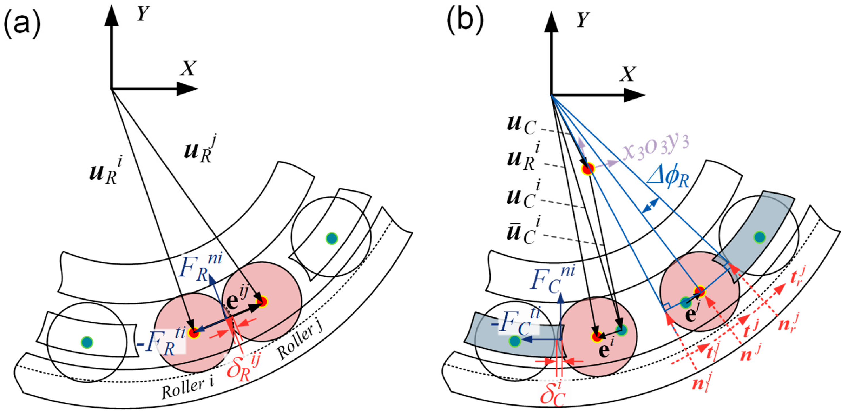
2.1.4. The Generalized Motion of the Roller

The motion of the roller not only needs to consider the radial and circumferential velocities and accelerations caused by external forces but also the effects of Coriolis acceleration and centripetal acceleration. Figure 6 shows a schematic of the forces acting on the roller.
Assuming that the displacement vector of roller i in its body coordinate system is u ¯ R i = u ¯ R i 0 T , the generalized displacement of roller i in XOY can be expressed as follows:
u R i = A i u ¯ R i
where A i is the planar rotation matrix of body i, expressed as follows:
A i = cos ϕ i sin ϕ i sin ϕ i cos ϕ i
Taking the second derivative of Equation (25) yields the following:
u ¨ R i = ϕ i ˙ 2 A i u ¯ R i n o r m a l + ϕ i ¨ A ϕ i u ¯ R i t a n g e n t i a l + 2 ϕ i ˙ A ϕ i u ¯ ˙ R i c o r i o l i s + A i u ¯ ¨ R i r a d i a l
where A ϕ i is the result of differentiating A i with respect to ϕ i , expressed as follows:
A ϕ i = sin ϕ i cos ϕ i cos ϕ i sin ϕ i
The circumferential velocity ϕ i ˙ and acceleration ϕ i ¨ of roller i are expressed as follows:
ϕ i ˙ = u ˙ R i · t 2 / u R i ϕ i ¨ = F R t i F I t i + F O t i · u R i / I ϕ
where I ϕ represents the moment of inertia relative to the origin of the global coordinate system XOY.
u ¯ ˙ R i = u ˙ R i · n 2 u ¯ ¨ R i = F I n i F O n i F R n i / m R i
where m R i is the mass of roller i.

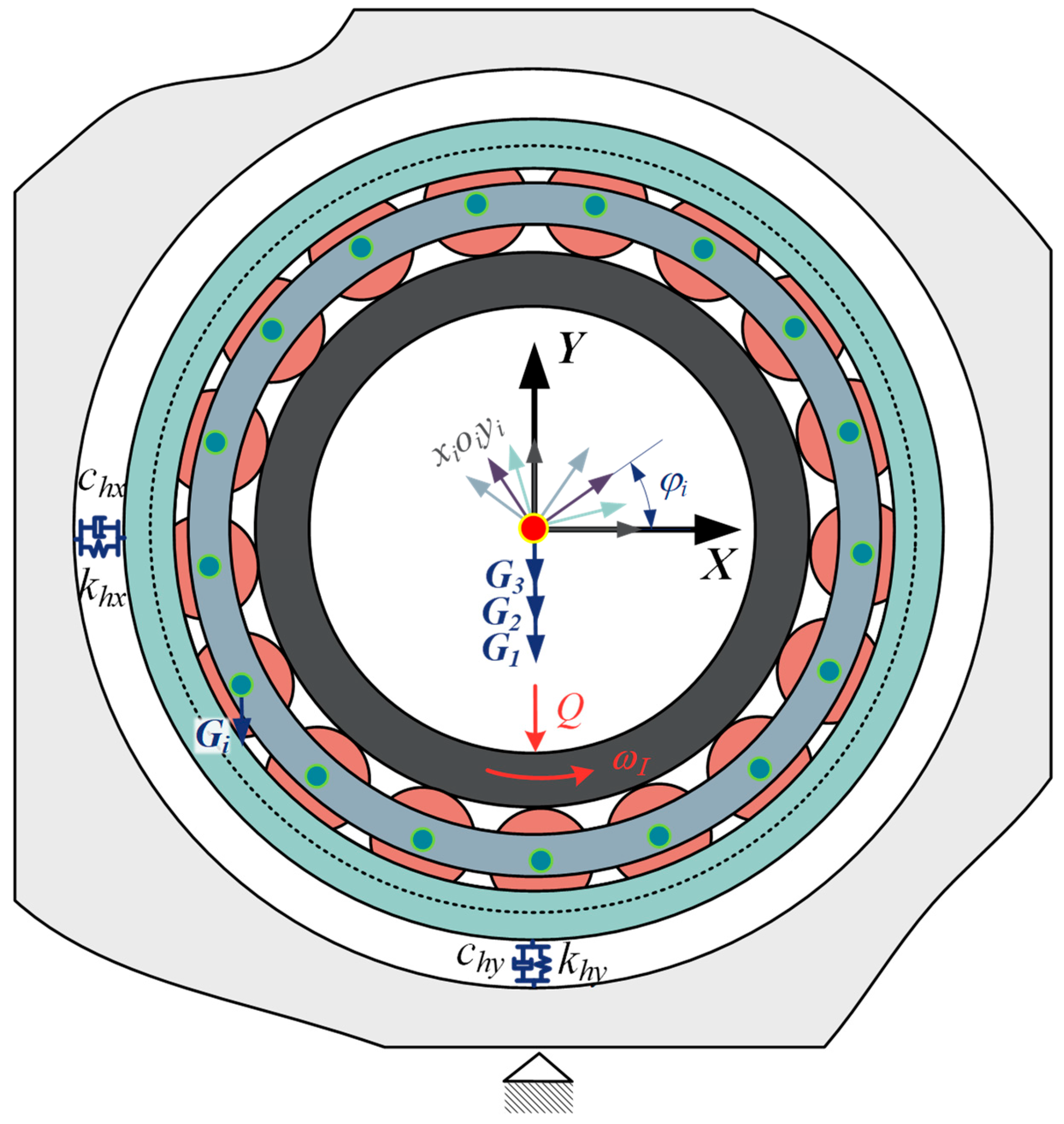
2.2. Modeling of DCRBs Multibody System

2.2.1. Multibody System DAEs

In the double-row cylindrical roller bearing multibody system, as illustrated in Figure 2, two coordinate systems are introduced: the global coordinate system XOY and the body-fixed coordinate system xioiyi, which is attached to the centroid of the object. Thus, the generalized coordinate vector of the system is defined as follows:
q = u 1 , φ 1 T , u 2 , φ 2 T , , u i , φ i T T
where u i = x i ,   y i represents the relative translational displacement vector of the body-fixed coordinate system fixed at the centroid of object i with respect to the global coordinate system, and φ 1 represents the relative rotational angle of the body-fixed coordinate system with respect to the global coordinate system.
In a multibody system, the motion of objects or the motion between objects may be subject to constraints. These constraints can be represented analytically as Φ q , t = 0 , referred to here as constraint equations. Additionally, Lagrange multipliers λ are introduced to determine the generalized constraint force vector. The equations of motion can then be expressed as follows:
M q ¨ = Q e Φ q T λ
where q ¨ represents the generalized acceleration vector, M denotes the system’s mass matrix, Q e is the generalized external force vector, and Φ q = Φ / q is the Jacobian matrix of the constraint equations.
The acceleration equation of the multibody system is expressed as follows:
Φ q q ¨ = Φ q q ˙ q q ˙ 2 Φ q t q ˙ Φ t t γ
The differential algebraic equation is obtained by combining Equations (32) and (33).
M Φ q T Φ q 0 q ¨ λ = Q e γ 2 α Φ ˙ + β 2 Φ
where α and β are Baumgarte feedback coefficient [26], used to stabilize the constraints in a multibody dynamics system.

2.2.2. The Dynamics Equations of the DCRB Multibody System

As shown in Figure 2, the multibody system consists of 5 + nr objects, including one bearing outer ring, one bearing inner ring, two bearing cages, nr rollers, and one bearing housing. The system has a total of 15 + 3nr degrees of freedom. For the regions without cage fracture, the contact between the roller and the cage pocket is treated as an ideal revolute pair. The bearing housing is considered a ground constraint, and the inner ring applies displacement, velocity, or acceleration driving constraints. The outer ring and bearing housing are press-fit, so rotational direction constraints are applied to the outer ring. For planar motion, an ideal revolute pair restricts the degrees of freedom in two translational directions. Driving and limiting constraints restrict one degree of freedom in the rotational direction. Lastly, the ground constraint restricts the degrees of freedom in three motion directions. Therefore, the remaining degrees of freedom for the double-row cylindrical roller bearing system are 10 + nr. In the case of a broken cage separator fault, the remaining degrees of freedom are 14 + nr. The system’s constraint equation vector is expressed as follows:
Φ q , t = Φ G 1 Φ S 1 Φ D 1 Φ R i = 0 , i = 1 , , n r
Φ G 1 represents the ground constraint exerted on the bearing housing, Φ S 1 represents the constraint limiting the rotation of the outer ring, Φ D 1 represents the driving constraint that drives the rotational direction of the inner ring, and Φ R i represents the revolute pair constraint between roller i and the cage pocket.
The earlier part of this chapter computed the contact and frictional forces between the rollers and the raceways, as well as the generalized accelerations of the rollers. In the case of a broken cage separator fault, the contact forces and frictional forces between the rollers and between the rollers and the cage wall were calculated. These forces were then transformed into the global coordinate system and assembled into the external force matrix of the system components to satisfy the needs of solving the dynamics equations.
Q e = Q e 0 Q e 1 Q e 2 Q e 3 Q e 4 Q e 4 + i , i = 1 , , n r
where
Q e 1 = F O X + k h x u o 1 + c h x u ˙ o 1 , F O Y + k h y u o 2 + c h y u ˙ o 2 m 1 g , M O T Q e 2 = F I X , F I Y m 2 g Q , M I T Q e 3 = j = n r / 2 1 n r / 2 F C x j , j = n r / 2 1 n r / 2 F C y j m 3 g , j = n r / 2 1 n r / 2 M C j T , j = n r / 2 1 , n r / 2 Q e 4 = j = n r 1 n r F C x j , j = n r 1 n r F C y j m 4 g , j = n r 1 n r M C j T , j = n r 1 , n r Q e 4 + i = m 4 + i u ¨ R i 1 + F R x j , m 4 + i u ¨ R i 2 m 4 + i g + F R y j , M R i + F R r n j F R l n j r R T , i = 1 , n r j = i = n r / 2 1 , n r / 2 , n r 1 , n r  
where
F R x j F R y j = sin ϕ i cos ϕ i cos ϕ i sin ϕ i F R t j F R n j
F R x j and F R y j represent the components of the external force acting on roller j in the global X- and Y-directions, respectively, under cage fault conditions. Similarly, u ¨ R i 1 and u ¨ R i 2 denote the components of the acceleration vector u ¨ R i of roller i in the global X- and Y-directions, respectively. Q is the radial load applied to the inner ring. k h x ,   k h y and c h x ,   c h y are the stiffness and damping coefficients between the bearing housing and the outer ring in the global X- and Y-directions, respectively. j represents the index of rollers within the defective cage pocket. When both cages are assumed to have faults at the same angular position, the indices of rollers within the faulty cage pocket are n r / 2 1 , n r / 2 , n r 1 , n r . If the fault location changes, the indices adjust accordingly.
In a multibody dynamic system, the addition of components increases the system’s degrees of freedom. During operation, the bearing is influenced by multiple factors, including generated heat, lubrication conditions, and contact topography, all of which require substantial computational power. To ensure the accuracy of the model, the following assumptions are made in this study:
  • The geometric center of each bearing component coincides with its center of mass.
  • All bearing components are considered rigid bodies, without accounting for elastic deformation.
  • The installation of bearing components does not consider human-induced errors, apart from the clearance allowance.
  • Contact between bearing components involves dry friction, ignoring the effects of frictional heat generation.

2.3. Model Solution Process and Model Validation

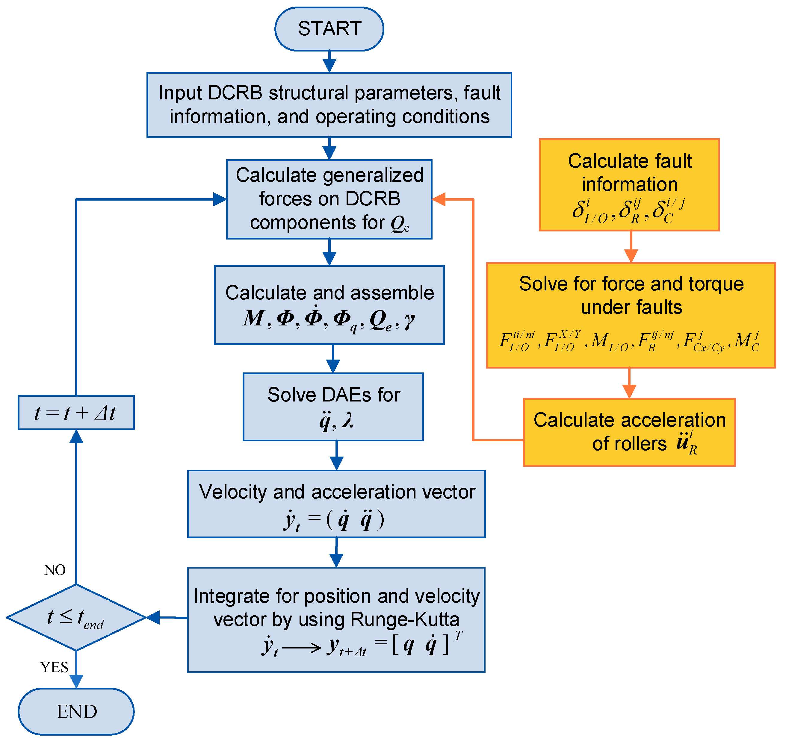
2.3.1. Model Solution Process

The solution of the ordinary differential equations uses the fourth-order explicit Runge–Kutta method [27]. This algorithm does not require evaluating partial derivatives but still maintains the same accuracy level as the Taylor method. It strikes a good balance between precision and computational complexity and is commonly used for rigid body problems. The algorithm is as follows:
y i + 1 = y i + h g
where h represents the integration step size.
  g = 1 6 f 1 + 2 f 2 + 2 f 3 + f 4 f 1 = f ( y i , t i ) f 2 = f ( y i + h 2 f 1 , t i + h 2 ) f 3 = f ( y i + h 2 f 2 , t i + h 2 ) f 4 = f ( y i + h f 3 , t i + h )
Figure 7 illustrates the flowchart of the entire calculation process, which can be categorized into the following steps. The first step involves inputting the structural information, fault conditions, and operating conditions of the double-row cylindrical roller bearing. The second step is to determine the applicable model for the contact between components based on the defect information and calculate the contact forces, friction forces, and constraint reaction forces between components to form the generalized external force matrix Qe. Then, the mass matrix M, constraint matrices Φ , Φ ˙ ,   γ , and the Jacobian matrix Φ q are assembled, which are required to solve the dynamics equations. The third step is to convert the multibody system’s DAEs into an n-th order ODE and use two new auxiliary vectors y = q q ˙ T and y ˙ = q ˙ q ¨ T to convert the problem into a stiff initial value problem y = f t , y ,   y 0 = y 0 . The fourth step involves time integration until the specified time node. The calculation uses the high-speed train axle box double-row cylindrical roller bearing NJ(P)3226X1, with its structural information as shown in Table 1.

2.3.2. Model Validation

Under ideal operating conditions, the rotational velocities of the bearing components should follow certain relationships. Since the outer ring is constrained by the interference fit with the bearing housing, its rotational velocity is not discussed. The inner ring is driven at a constant velocity ωI, while the rotational velocities of the cage and roller, ωC and ωR, are given by
ω C = ω I × r I 2 × r I + r R
ω R = ω I ω C × r I r R
Figure 8 records the variation in the rotational velocities of the bearing components from the start-up to the end of the 3 s simulation. At the beginning of the simulation, the bearing has not yet reached a steady-state operation. After 0.1 s, there is an indication of the establishment of steady-state operation. The inner ring is driven at a constant speed of 1200 rpm, corresponding to a theoretical value of 124.8 rad/s. The calculated theoretical rotational velocities for the cage and roller are 52.4 rad/s and −380.5 rad/s, respectively, with the results aligning well with the theoretical values. As the roller passes through the loading zone, fluctuations occur, leading to rapid oscillations in the rotational speed several times during the 3 s simulation.

3. Results and Discussion

3.1. Analysis of the Tribological Behavior of Defective DCRBs

Figure 9a shows the relationship between the contact force between the roller and the inner raceway and the variation in the roller’s azimuth angle during its motion. The orange line represents the total force exerted by all rollers on the inner ring, which is consistent with the applied load of 100 kN, and the support reaction force remains close to 100 kN throughout the operation. The blue line represents the contact force between a single roller and the inner ring as its azimuth angle varies from −90 degrees to 90 degrees. The azimuth angle is measured relative to the Y-axis. Due to radial clearance, contact between the roller and the raceway only occurs within the −30 degrees to 30 degrees range, known as the loading zone, where the maximum contact force of approximately 30 kN is reached near 0 degrees. Figure 9b shows the friction force corresponding to the contact force between a single roller and the inner raceway. The magnitude of the friction force increases as the contact force of the roller in Figure 9a increases, reaching a maximum of approximately 1.5 kN near 0 degrees. The direction of the friction force continuously changes, causing the friction force to alternate between positive and negative values.
Figure 9c represents the relative sliding velocity of a single roller with respect to the inner ring. In an ideal and stable operating environment, the theoretical value of the relative sliding velocity should be 0. However, in actual operation, the displacement of the inner ring caused by clearance leads to a larger relative sliding velocity when the roller is in the non-loading zone. The relative sliding velocity decreases in the loading zone and approaches 0. Figure 9d shows the global rotational velocity of the roller, with counterclockwise motion as positive. The roller rotates in the clockwise direction, so the rotational velocity is negative. It can be observed that in the non-loading zone, the roller’s rotational velocity is lower than the theoretical rotational velocity due to relative sliding with the inner ring. In the loading zone, the relative sliding decreases, and the roller’s rotational velocity fluctuates around the theoretical value.
Figure 10 illustrates the contact friction between the roller and the raceway under fault and normal conditions. From top to bottom, the subfigures represent the following: (a) the total contact force in the global Y-direction exerted by all rollers on the inner raceway, (b) the contact force of a single roller with the raceway, and (c) the frictional torque of a single roller with the raceway. The x-axis represents the position angle of the roller within the raceway. Figure 10b shows the contact and friction behavior of the roller with the raceway under cage fracture, where the roller is located in a cage with a broken separator. Compared to the defect-free bearing, it is observed that the loading area of the roller in the faulty cage is larger and asymmetric. This is due to the different contact conditions on either side of the roller: one side is in contact with the normal cage wall, and the other side is in contact with the missing cage, which provides greater freedom of movement. Moreover, since the roller and the cage are no longer ideal rotational pairs, the fluctuations in the contact friction force between the roller and the inner raceway are more pronounced. Figure 10c shows the results of the inner raceway defect. The defective area on the inner raceway rotates with the inner ring. The contact force only undergoes a sudden change when the roller in the contact area encounters the defective area. Corresponding sudden changes in frictional torque are also observed. Figure 10d displays the results of the outer raceway defect. As the defect is located at the center of the loading area, each roller passing through the loading zone causes a sudden change in both the contact force and the frictional torque. The contact force and frictional torque shown for a single roller are generated by the interaction with the outer ring. A large sudden change occurs when the roller passes near 0 degrees, and subsequent changes are caused by the previous and subsequent rollers. From the above analysis, it can be concluded that all three fault conditions affect the friction torque experienced by the roller. Cage fracture leads to more unstable fluctuations, while raceway defects cause periodic sudden changes.

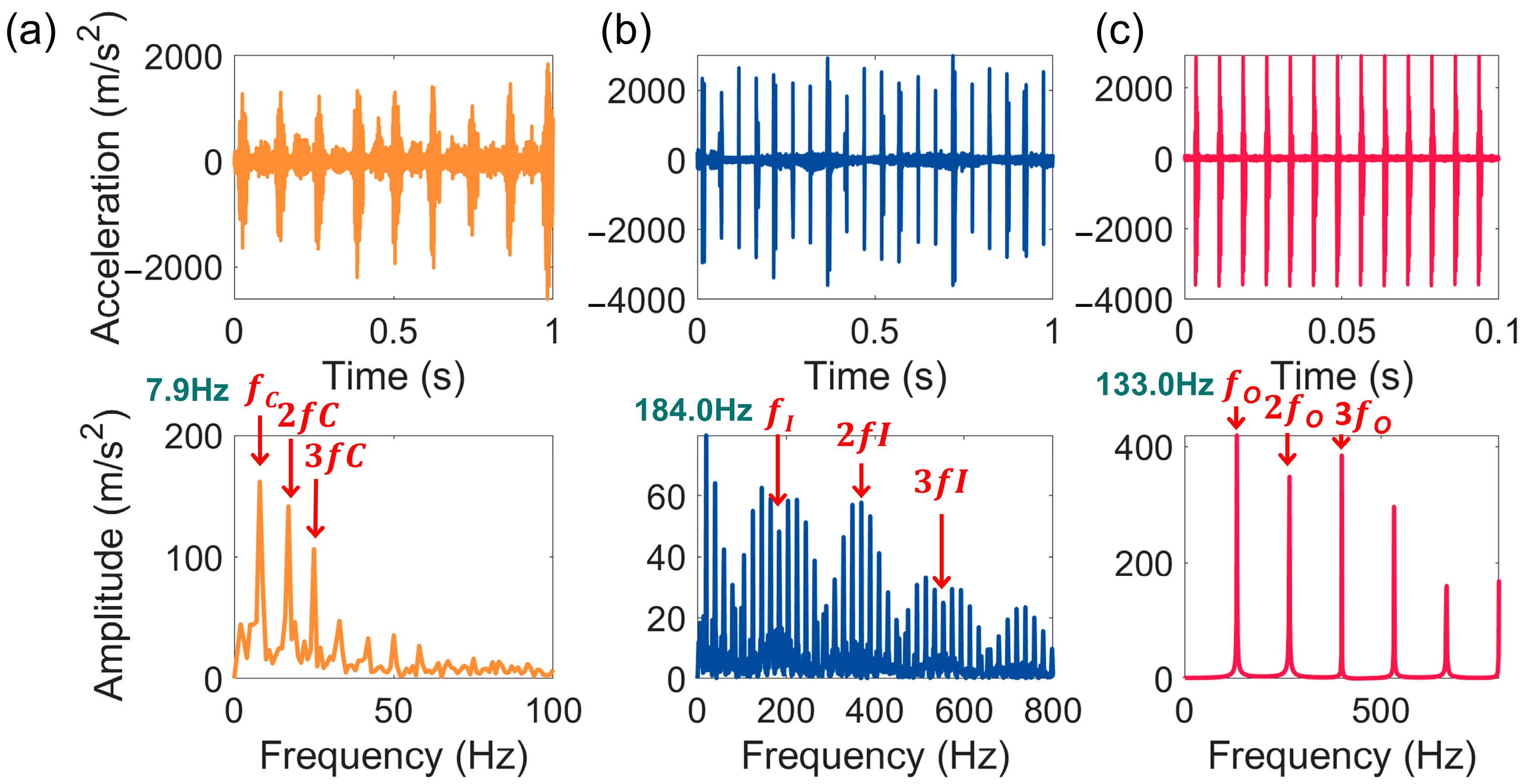
3.2. Analysis of the Dynamic Response of Defective DCRBs

When a bearing experiences a fault, different defective components will exhibit periodicity in the vibration signal depending on the fault location. By performing envelope demodulation on the signal, the periodic variations in the signal can be more intuitively observed in the frequency domain. In this study, faults in the cage, inner ring, and outer ring are simulated, and their corresponding theoretical characteristic frequencies f c , f I   , and f O can be calculated using the following formulas:
f c = 1 2 1 r r r m f r
f I = n r 2 1 + r r r m f r
f O = n r 2 1 r r r m f r
where f r represents the rotational frequency, which appears in the signal of the inner ring fault. Additionally, information related to the rotational frequency will also appear near the fundamental frequency and its harmonics of the inner ring fault characteristic frequency.
Figure 11 illustrates the vibration responses of cage, inner ring, and outer ring faults under an inner ring driving speed of ωI = 1200 rpm, corresponding to a rotational frequency of f r = 20   H z . The upper row shows the time-domain acceleration signals at a fixed position on the outer ring, while the lower row displays the corresponding envelope spectrum. According to Equations (43)–(45), the theoretical characteristic frequencies are f C = 8.4   H z , f I = 185.5   H z , and f O = 134.5   H z . Figure 11a presents the vibration signal for a cage fault caused by the cage pillar fracture. The dominant frequency is 7.9 Hz, which agrees well with the theoretical value of 8.4 Hz. Figure 11b shows the vibration response of an inner ring fault, with a dominant frequency of 184 Hz, matching the theoretical value of 185.5 Hz. The frequency spectrum for the inner ring fault exhibits a unique characteristic: instead of isolated peaks at the characteristic frequency and its harmonics, additional peaks spaced by the rotational frequency appear on both sides of the primary peaks, decreasing in magnitude progressively. This phenomenon aligns better with the actual operational behavior of bearings and arises due to the installation clearance and load-induced displacement. These factors cause the inner ring’s center of mass to deviate from that of the outer ring, leading to the influence of rotational frequency. Figure 11c represents the vibration signal for an outer ring fault, with a dominant frequency of 133 Hz, closely matching the theoretical value of 134.5 Hz. In summary, the proposed model effectively simulates the operational behavior of bearings under cage, inner ring, and outer ring faults.

4. Conclusions

This paper establishes a numerical model for a double-row cylindrical roller bearing in an axle box, incorporating inner and outer raceway faults as well as cage faults. The model effectively simulates the dynamic behavior of the bearing under both normal and faulty conditions, with a particular focus on raceway and cage faults. The analysis reveals the mechanisms behind fault-induced impacts: raceway faults are caused by collisions between rollers and defective areas of the raceway, while cage faults result from irregular roller motions within the cage pockets. By validating the model against fault characteristic frequencies, this study provides a reliable tool for simulating the vibration response of bearings under various fault conditions. The proposed approach offers a versatile framework for the numerical simulation of different bearing models and types, contributing valuable insights for fault diagnosis and bearing health monitoring in industrial applications.

Author Contributions

Conceptualization, L.F. and X.Z.; Methodology, L.F.; Validation, X.Z., W.H. and X.H.; Investigation, L.F., X.Z., W.H. and C.M.; Resources, L.F.; Writing—original draft, L.F. and X.Z.; Writing—review & editing, L.F., X.Z., W.H., C.M. and X.H.; Visualization, X.Z.; Supervision, L.F. and C.F.; Project administration, L.F., C.M. and C.F.; Funding acquisition, L.F. All authors have read and agreed to the published version of the manuscript.

Funding

This work is supported by the Key Project of Scientific Research Project of Hunan Provincial Department of Education (Grant No. 24A0015).

Data Availability Statement

The original contributions presented in this study are included in the article. Further inquiries can be directed to the corresponding author.

Acknowledgments

The authors are thankful to the anonymous reviewer for the extremely fruitful reviewing of the manuscript.

Conflicts of Interest

The authors declare no conflicts of interest.

Nomenclature

A i Planar transformation matrix;
A ϕ i Derivative of A i with respect to ϕ i ;
b1/2Width of inner/outer raceway defect (m);
c p Radial clearance between roller and cage pocket (m);
c h x ,   c h y Damping of the outer ring and the bearing housing (Ns/m);
dO, dI, dRDiameters of the outer raceway, inner raceway and roller (m);
dMPitch diameter (m);
d ϕ i 1 / 2 Effective depth of roller and inner/outer raceway (m);
c s Stick–slip effect coefficient;
Ei, EjElastic modulus of cylinder i and j (GPa);
E Composite elastic modulus (GPa);
f O , f I , f c Calculated frequency of outer ring/inner ring/cage (Hz);
FnIndentation contact force (N);
F I X ,   F I Y Contact force acting on inner ring (N);
F O X ,   F O Y Contact force acting on outer ring (N);
F C x j ,   F C y j Contact force that roller j acting on cage (N);
F I n i ,   F I t i Normal and tangential components of contact force between the inner raceway and roller i (N);
F O n i ,   F O t i Normal and tangential components of contact force between the outer raceway and roller i (N);
F R l / r n j , F R l / r t j Normal and tangential components of contact force between left/right pocket side and roller j (N);
F R R n i , F R R t i Normal and tangential components of contact force that roller j acting on roller i (N);
F R C n i , F R C t i Normal and tangential components of contact force between roller i and cage pocket (N);
I ϕ Moment of inertia around the central axis of the outer ring (kg·m2);
k h x ,   k h y Stiffness of the outer ring and the bearing housing (N/m);
LCylinder length (m);
MMass matrix of a multibody system;
m R i Mass of roller i (kg);
nrNumber of rollers;
n 1 / 2 Unit vector along the contact force between the inner/outer raceway and roller i;
QRadial load (N);
Q ψ Radial load on rolling element (N);
Q e Generalized external force vector (N);
R * Equivalent radius (m);
Ri, RjRadii of cylinder i and j (m);
rO, rI, rRRadii of the outer raceway, inner raceway and roller (m);
tTime (s);
t 1 / 2 Unit vector along the contact force between the inner/outer raceway and roller i;
UNon-dimension parameter of velocity;
u R R i j Sliding velocity of contact surfaces for roller i relative to roller j (m/s);
u R C i Sliding velocity of contact surfaces for roller i relative to pocket (m/s);
u 1 / 2 Relative velocity between the inner/outer raceway and roller (m/s);
u R i , u I Displacement vectors of roller i and inner ring (m);
u B i Relative displacement vector of roller i (m)s;
u i Global translation position vector of the reference frame origin on body i (m);
vi, vjPoisson’s ratio of cylinder i and j;
vsStribeck velocity (m/s);
WNon-dimension parameter of load;
wContact load (N).
Greek letters
γExternal generalized force vector;
δIndentation depth (m);
δ I i ,   δ O i Contact deformation between inner/outer raceway and roller i (m);
δ R i j Contact deformation for roller i relative to roller j (m);
δ C i Contact deformation for roller i relative to pocket (m);
λVector of Lagrange multipliers;
μ s ,   μ k Static and kinetic friction coefficients;
φ i Rotation displacement of the reference frame along with the rotation of body i (rad);
ΦqJacobian matrix of constraint equations;
Φ Constraint equations of multibody system;
ϕ 1 i ,   ϕ 2 i Azimuth angle of roller i with respect to inner/outer ring center (rad);
ΨAngular position of the roller to the y axis (rad);
ωIAngular velocity of inner ring (rpm);
ωCAngular velocity of cage (rpm).
Coordinate systems
XOYGlobal coordinate system in the outer ring center;
xioiyiReference coordinate system fixed on the body i.
Abbreviations
DCRBDouble-row cylindrical roller bearing.

References

  1. Xu, H.; Ma, H.; Wen, B.; Yang, Y.; Li, X.; Luo, Z.; Han, Q.; Wen, B. Dynamic characteristics of spindle-bearing with tilted pedestal and clearance fit. Int. J. Mech. Sci. 2024, 261, 108683. [Google Scholar] [CrossRef]
  2. Tingarikar, G.; Choudhury, A. Vibration Analysis-Based Fault Diagnosis of a Dynamically Loaded Bearing with Distributed Defect. Arab. J. Sci. Eng. 2022, 47, 8045–8058. [Google Scholar] [CrossRef]
  3. Patel, S.P.; Upadhyay, S.H. Influence of roller defect and coupled roller–inner–outer race defects on the performance of cylindrical roller bearing. Proc. Inst. Mech. Eng. Part K J. Multi-Body Dyn. 2019, 233, 731–746. [Google Scholar] [CrossRef]
  4. Liu, J.; Wang, L.; Shi, Z. Dynamic modelling of the defect extension and appearance in a cylindrical roller bearing. Mech. Syst. Signal Process. 2022, 173, 109040. [Google Scholar] [CrossRef]
  5. Tu, W.; Yu, W.; Shao, Y.; Yu, Y. A nonlinear dynamic vibration model of cylindrical roller bearing considering skidding. Nonlinear Dyn. 2021, 103, 2299–2313. [Google Scholar] [CrossRef]
  6. Chen, Y.; Zhang, H.; Li, X.; Xiao, S.; Gu, F.; Shi, Z. Effects of Wear on Lubrication Performance and Vibration Signatures of Rotor System Supported by Hydrodynamic Bearings. Lubricants 2023, 11, 107. [Google Scholar] [CrossRef]
  7. Tofighi-Niaki, E.; Safizadeh, M.S. Dynamic of a Flexible Rotor-Bearing System Supported by Worn Tilting Journal Bearings Experiencing Rub-Impact. Lubricants 2023, 11, 212. [Google Scholar] [CrossRef]
  8. Wu, Z.; Tang, H.; Li, Y.; Ren, Y.; Chen, L.; Kumar, A. Simulation and experimental analysis of rotor-bearing system with rolling element bearing fault in axial piston pump under churning condition. Proc. Inst. Mech. Eng. Part K J. Multi-Body Dyn. 2022, 237, 98–113. [Google Scholar] [CrossRef]
  9. Li, N.; Zhang, J.; Meng, X.; Han, Q.; Zhai, J. Dynamic response and failure analysis of bearing under the impact of vibration excitation. Eng. Fail. Anal. 2023, 154, 107640. [Google Scholar] [CrossRef]
  10. Peng, H.; Zhang, H.; Fan, Y.; Shangguan, L.; Yang, Y. A Review of Research on Wind Turbine Bearings’ Failure Analysis and Fault Diagnosis. Lubricants 2023, 11, 14. [Google Scholar] [CrossRef]
  11. Li, X.; Liu, J.; Ding, S.; Xu, Y.; Zhang, Y.; Xia, M. Dynamic modeling and vibration analysis of double row cylindrical roller bearings with irregular-shaped defects. Nonlinear Dyn. 2023, 112, 2501–2521. [Google Scholar] [CrossRef]
  12. Shinde, P.V.; Desavale, R.G. Application of dimension analysis and soft competitive tool to predict compound faults present in rotor-bearing systems. Measurement 2022, 193, 110984. [Google Scholar] [CrossRef]
  13. Zhao, Y.; Chen, Z.; Zi, Y.; Zhang, M.; Tang, T. Dynamic Effect Analysis of Cryogenic Solid-Lubricated Ball Bearings with Geometrical-Frictional Defects. Lubricants 2024, 12, 84. [Google Scholar] [CrossRef]
  14. Deng, W.; Li, Z.; Li, X.; Chen, H.; Zhao, H. Compound fault diagnosis using optimized MCKD and sparse representation for rolling bearings. IEEE Trans. Instrum. Meas. 2022, 71, 1–9. [Google Scholar] [CrossRef]
  15. Denni, M.; Biboulet, N.; Abousleiman, V.; Lubrecht, A.A. Dynamic study of a roller bearing in a planetary application considering the hydrodynamic lubrication of the roller/cage contact. Tribol. Int. 2020, 149. [Google Scholar] [CrossRef]
  16. Wang, P.; Yang, Y.; Ma, H.; Xu, H.; Li, X.; Luo, Z.; Wen, B. Vibration characteristics of rotor-bearing system with angular misalignment and cage fracture: Simulation and experiment. Mech. Syst. Signal Process. 2023, 182, 109545. [Google Scholar] [CrossRef]
  17. Li, H.; Li, H.; Liu, Y.; Liu, H. Dynamic characteristics of ball bearing with flexible cage lintel and wear. Eng. Fail. Anal. 2020, 117, 104956. [Google Scholar] [CrossRef]
  18. Shi, Z.; Liu, J.; Li, H.; Zhang, Q.; Xiao, G. Dynamic simulation of a planet roller bearing considering the cage bridge crack. Eng. Fail. Anal. 2022, 131, 105849. [Google Scholar] [CrossRef]
  19. Luo, Y.; Tu, W.; Fan, C.; Zhang, L.; Zhang, Y.; Yu, W. A study on the modeling method of cage slip and its effects on the vibration response of rolling-element bearing. Energies 2022, 15, 2396. [Google Scholar] [CrossRef]
  20. Skrinjar, L.; Slavič, J.; Boltežar, M. A review of continuous contact-force models in multibody dynamics. Int. J. Mech. Sci. 2018, 145, 171–187. [Google Scholar] [CrossRef]
  21. Muvengei, O.; Kihiu, J.; Ikua, B. Dynamic analysis of planar multi-body systems with LuGre friction at differently located revolute clearance joints. Multibody Syst. Dyn. 2012, 28, 369–393. [Google Scholar] [CrossRef]
  22. Ju, C. Modeling Friction Phenomena and Elastomeric Dampers in Multibody Dynamics Analysis; Georgia Institute of Technology: Atlanta, GA, USA, 2009. [Google Scholar]
  23. Kermani, M.; Patel, R.; Moallem, M. Friction identification in robotic manipulators: Case studies. In Proceedings of the Proceedings of 2005 IEEE Conference on Control Applications, 2005, CCA 2005, Toronto, ON, Canada, 28–31 August 2005; pp. 1170–1175. [Google Scholar]
  24. De Wit, C.C.; Lischinsky, P. Adaptive friction compensation with partially known dynamic friction model. Int. J. Adapt. Control Signal Process. 1997, 11, 65–80. [Google Scholar] [CrossRef]
  25. Pereira, C.; Ramalho, A.; Ambrosio, J. An enhanced cylindrical contact force model. Multibody Syst. Dyn. 2015, 35, 277–298. [Google Scholar] [CrossRef]
  26. Baumgarte, J. Stabilization of constraints and integrals of motion in dynamical systems. Comput. Methods Appl. Mech. Eng. 1972, 1, 1–16. [Google Scholar] [CrossRef]
  27. Tan, D.; Chen, Z. On a general formula of fourth order Runge-Kutta method. J. Math. Sci. Math. Educ. 2012, 7, 1–10. [Google Scholar]
Figure 1. Bearing NJ(P)3226X1.
Lubricants 13 00080 g001
Figure 2. DCRB system.
Lubricants 13 00080 g002
Figure 3. Inner raceway fault: (a) deformation depth of roller–inner raceway; (b) deformation depth of roller–inner raceway under defective area.
Lubricants 13 00080 g003
Figure 4. Outer raceway fault: (a) deformation depth of roller–outer raceway; (b) deformation depth of roller–outer raceway under defective area.
Lubricants 13 00080 g004
Figure 5. Cage fracture fault: (a) roller–roller contact; (b) roller–cage pillar contact.
Lubricants 13 00080 g005
Figure 6. Force conditions of roller i.
Lubricants 13 00080 g006
Figure 7. Flowchart of the computation process.
Lubricants 13 00080 g007
Figure 8. Rotational velocity of the bearing components (ωI = 1200 rpm).
Lubricants 13 00080 g008
Figure 9. Roller-raceway contact forces, friction, and motion characteristics (Q = 100 kN, ωI = 1200 rpm): (a) contact force; (b) friction force; (c) sliding velocity; (d) roller rotation speed.
Lubricants 13 00080 g009
Figure 10. Contact friction between rollers and raceways under normal and fault conditions (Q = 100 kN): (a) defect-free; (b) cage fracture; (c) inner raceway defect; (d) outer raceway defect.
Lubricants 13 00080 g010
Figure 11. The acceleration of the outer ring and corresponding envelop spectrum (ωI = 1200 rpm): (a) cage fracture; (b) inner raceway defect; (c) outer raceway defect.
Lubricants 13 00080 g011
Table 1. Parameters of the NJ(P)3226X1 bearing.
ParametersValueParametersValue
Inner raceway radius rI (m)78.86 × 10⁻³Mass of cage mC (kg)2.459
Outer raceway radius rO (m)
Pitch radius rM (m)
109.14 × 10⁻³
94 × 10−3
Inertial moment of cage IC (kg·m2)2.19 × 10⁻²
Roller radius rR (m)15 × 10−3Mass of roller mR (kg)2.48 × 10⁻¹
Roller length lR (m)
Roller number nr (m)
48 × 10−3
16 × 2
Inertial moment of roller IR (kg·m2)6.15 × 10⁻⁵
Elastic modulus E (GPa)
Poisson’s radio ν (-)
207.5
0.3
Stiffness of the outer ring and the bearing housing khx, khy (N/m)212 × 106
Mass of outer ring mO (kg)
Inertial moment of outer ring IO (kg·m2)
1.349 × 101
1.66 × 10⁻¹
Damping of the outer ring and the bearing housing chx, chy (Ns/m)1.0 × 105
Mass of inner ring mI (kg)7.316
Inertial moment of inner ring II (kg·m2)3.82 × 10⁻²
Disclaimer/Publisher’s Note: The statements, opinions and data contained in all publications are solely those of the individual author(s) and contributor(s) and not of MDPI and/or the editor(s). MDPI and/or the editor(s) disclaim responsibility for any injury to people or property resulting from any ideas, methods, instructions or products referred to in the content.

