1. Introduction
The rapid advancement of space technology is placing ever-increasing demands on the control precision, response speed, and service life of attitude-control actuators for spacecraft, including satellites, manned vehicles, and space stations [
1,
2,
3]. The Control Moment Gyro (CMG) is a core inertial actuator in satellite and spacecraft attitude control systems. Valued for its high output torque and rapid response, it is widely employed in large spacecraft and high-precision pointing satellites. The CMG comprises a high-speed rotor-bearing system and a frame assembly. Its principle of operation is based on a high-speed rotor generating constant angular momentum. The frame assembly then drives the rotor in a low-speed reciprocating motion around an axis perpendicular to the angular momentum vector to alter its direction, thereby producing a control torque. This torque facilitates angular momentum exchange with the spacecraft, resulting in precise attitude control [
4,
5,
6,
7,
8,
9,
10,
11,
12]. However, the performance of the CMG is critically dependent on the long-term stability of its bearing-rotor system. Prolonged in-orbit service leads to lubrication degradation, which manifests as abnormal operating currents and speed responses [
13]. In severe cases, this progression can cause bearing seizure or complete failure. These failures induce degradation in friction performance, elevated torque fluctuations, and ultimately a loss of attitude control accuracy, posing a critical risk to mission reliability [
14,
15,
16,
17].
The lubrication research of CMG bearings presents significant challenges due to their complex motion patterns and operating conditions. On one hand, during operation, multiple contact forms exist between the inner ring, outer ring, cage, and balls, while the balls themselves undergo compound motion involving revolution, rotation, and sliding. On the other hand, factors such as machining errors in bearing components (e.g., roundness deviation, waviness, and surface roughness), vibrations induced by bearing clearance, and elastic deformation between balls and raceways interact synergistically. This interplay collectively results in highly nonlinear and time-varying characteristics of contact mechanics and friction torque [
18,
19,
20,
21]. Furthermore, lubrication behavior under vacuum conditions differs fundamentally from that in terrestrial environments [
22]. These factors, compounded by the stringent requirements for long service life and high reliability, make lubrication research for CMG bearings exceptionally difficult. Currently, the lubrication and life assessment of CMG bearings predominantly rely on 1:1 scale running-in tests. Although this approach offers a direct assessment, it is time-consuming, costly, and lacks the capacity for rapid, accurate evaluation of lubrication status and service life, consequently hindering the elucidation of underlying mechanisms and accurate prediction of in-orbit performance evolution. Therefore, the development of a test system that can accurately simulate rolling element lubrication state while incorporating multi-parameter in situ monitoring is essential for advancing the understanding of bearing tribology, enabling precise life prediction, and ultimately improving the on-orbit reliability of CMGs.
To investigate the lubrication behavior of bearing rolling elements, researchers have designed and developed various types of ball-on-disc tribometers. Utilizing these devices, they have conducted in-depth studies on the friction and wear characteristics of bearings and related patterns. As early as the 1960s, Gohar et al. [
23] designed a ball-on-disc friction tester capable of measuring lubricant film thickness. By applying optical interferometry to quantify elastohydrodynamic lubrication (EHL) films, this apparatus provided an effective method for analyzing the lubrication state of rolling bearings. Over the subsequent decades, ball-on-disc testers have continued to serve as a fundamental experimental platform for investigating the lubrication behavior of bearings, evolving alongside technological advancements. For instance, Cann [
24] developed an advanced ball-on-disc apparatus capable of simulating realistic bearing operating conditions and lubricant supply configurations. By integrating optical interferometry with infrared spectroscopy, this system enabled detailed analysis of grease behavior within rolling bearing contacts. Liang et al. [
25] developed a high-speed ball-on-disc tribometer capable of operating at sliding velocities up to 100 m/s, with the ability to measure lubricant film thickness within a 42 m/s range, thereby enabling precise characterization of lubrication regimes. However, this apparatus lacks the capability to simulate vacuum environments. In a complementary approach, Ma et al. [
26] designed a vacuum tribometer that facilitates ball-on-disc testing under high vacuum conditions (1 × 10
−5 Pa). A limitation of this setup is that the ball specimen remains stationary during testing, restricting the contact to pure sliding friction. Consequently, it cannot replicate the complex compound motions—such as combined rolling and spinning—typical of actual bearing rolling elements. Li et al. [
27] developed a ball-on-ring contact system to simulate the interaction between rolling elements and the outer raceway. This system enables friction measurement under various slide-to-roll ratios by independently controlling the rotational speeds of the ball and ring. However, it is incapable of simulating vacuum environments or replicating the orbital motion of rolling elements. Furthermore, the measurable parameters are limited to friction force and the friction coefficient, which are insufficient for a comprehensive evaluation of the lubrication behavior of bearing rolling elements under vacuum conditions. The ball-on-disc tribometer developed by Liu et al. [
28] is capable of operating over a broad temperature range from −175 °C to ambient temperature. It enables accurate measurement of the friction coefficient of lubricants under simulated bearing sliding and rolling conditions. However, this device is unable to simulate a vacuum environment or replicate the orbital motion of bearing rolling elements.
Despite considerable progress, existing test rigs remain incapable of accurately simulating the combined rotational and orbital motion of bearing rolling elements under vacuum conditions. Moreover, they generally lack the capability for in situ real-time monitoring of the lubrication status within the contact area. Therefore, this study developed a simulation system with integrated in situ monitoring capabilities for the lubrication state of rolling elements in space CMG bearings. The system accurately replicates the lubrication state during combined rotational and orbital motion under vacuum while enabling in situ real-time monitoring of key parameters including friction force, surface morphology evolution, tribochemical changes, lubricant depletion, and gaseous reaction products. The core functions and performance metrics of the system have been systematically validated.
2. Principle of the System
The system developed in this study primarily consists of a vacuum and motion simulation module, an in situ monitoring module, and a data acquisition and control module. The vacuum and motion simulation module simulates the compound motion and lubrication state of a bearing rolling element—including its rotation, revolution, and sliding—under vacuum conditions. The in situ monitoring module continuously tracks the friction forces, surface morphology evolution, tribochemical properties, lubricant dissipation, and gaseous byproducts during the operation of a bearing rolling element.
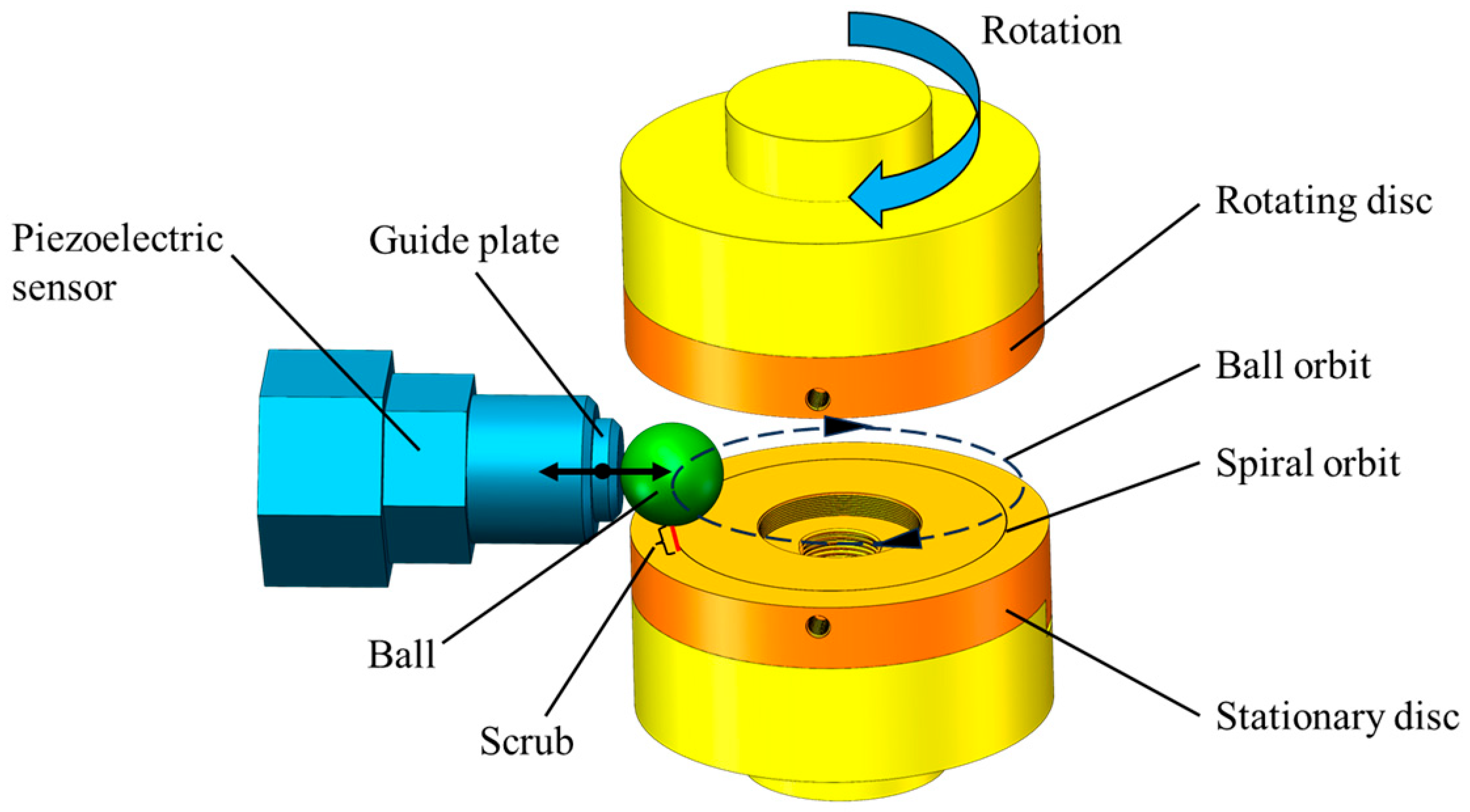
The vacuum and motion simulation module employs a stationary disc, a rotating disc, and a lubricated steel ball that rolls and pivots between them to simulate the motion and lubrication conditions of a bearing rolling element, as shown in
Figure 1. Its operating principle is as follows: First, a load is applied to the stationary disc, positioning the lubricated steel ball between the rotating and stationary discs. Next, the rotating disc is driven at a specific speed, causing the steel ball to undergo both rotation and revolution, thereby simulating the contact motion state of a rolling element within a bearing. Simultaneously, the centrifugal force generated by the revolution causes the steel ball to follow a spiral trajectory. To prevent the steel ball from being ejected from the stationary disc, a guide plate is installed on the outer side of the stationary disc. Collisions between the steel ball and the guide plate redirect the ball back onto its intended orbital path [
29].
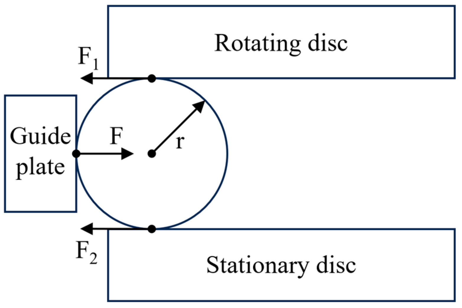
The measurement of the coefficient of friction is based on the unique mechanical design of the spiral orbit tribometer. When the loaded steel ball enters the scrubbing zone and collides with the guide disc, it undergoes macroscopic radial sliding at the point of contact with the rotating disc, thereby generating a radial sliding friction force [
30]. To counterbalance the torque generated by this friction force, the stationary disc must apply an equal and opposite radial force to the ball, as shown in
Figure 2.
At this point, the linear relationship between the piezoelectric force sensor measurement and the sliding friction force is:
In Equations (1) and (2), is the sliding friction force exerted by the rotating disc on the ball, measured in N; is the radial force exerted by the stationary disc on the ball, measured in N; is the measured value from the piezoelectric force sensor, measured in N; is the radius of the ball.
From this, the formula for calculating the friction coefficient can be derived:
In Equation (3),
μ is the friction coefficient, and
is the normal load, measured in N. This relationship has been proven in Reference [
30].
The in situ monitoring module primarily consists of a friction force monitoring unit, an in situ morphology observation unit, a Raman spectroscopy detection unit, and a gas detection unit. The friction monitoring unit acquires real-time friction signals between the steel ball and both discs while calculating the coefficient of friction. The in situ morphology observation unit monitors the surface morphology evolution of the stationary disc online. The Raman spectroscopy detection unit analyzes dynamic changes in the surface friction chemistry of the stationary disc online. The gas detection unit tracks lubricant dissipation and identifies potential gas decomposition products.
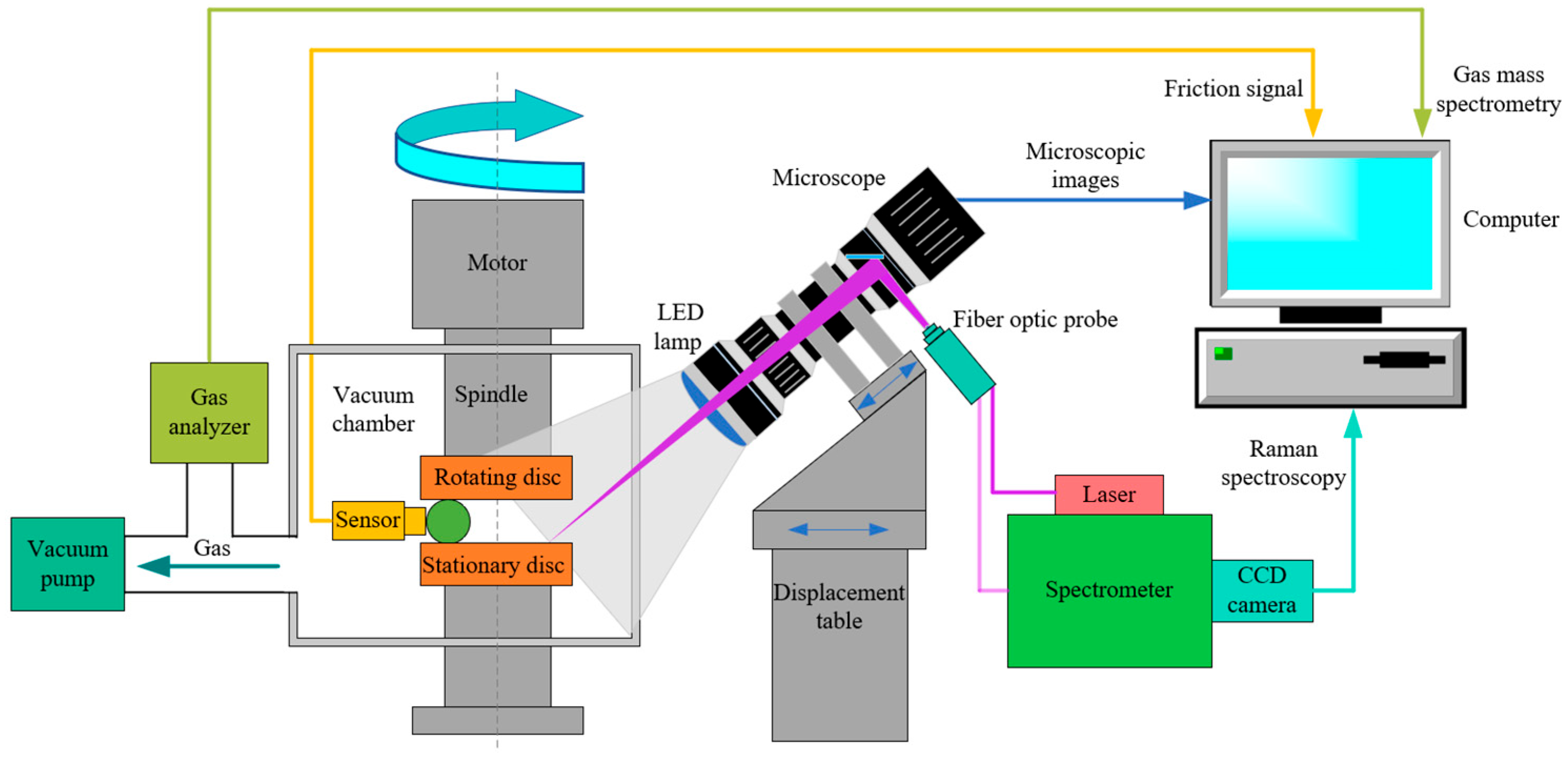
The operating principle of the in situ monitoring module is illustrated in
Figure 3. As the rotating disc turns, the steel ball follows a spiral trajectory. Upon colliding with the guide plate equipped with piezoelectric sensors, the ball returns to its original path. During this process, the piezoelectric sensors continuously capture friction force signals generated by the collision and transmit them to a computer for acquisition and processing. Simultaneously, an optical microscope is aligned with the stationary disc’s surface through the vacuum chamber’s observation window. A displacement stage enables fine adjustment and precise focusing of the microscope. The computer enables real-time observation of friction trajectories and wear morphology on the stationary disc’s surface. For Raman spectroscopy monitoring, the laser light passes through the excitation path and is introduced into the vacuum chamber via the observation window, focused onto the stationary disc’s surface. The resulting Raman-scattered light is collected and directed back through the same optical path to the spectrometer for analysis. The generated spectra are then displayed and processed on the computer. Additionally, the system continuously extracts residual gases from the chamber via a vacuum pump and directs them into a gas analyzer. Analysis results are displayed on the computer, enabling online monitoring and analysis of volatiles and gas composition.
3. Development of the System
3.1. Vacuum and Motion Simulation Module
The main structure of the simulation system with integrated in situ monitoring capabilities is shown in
Figure 4. The lubrication state of the CMG bearing rolling element under vacuum conditions differs significantly from that in atmospheric-pressure ground environments. To more accurately simulate the operational environment of the CMG bearing rolling element in space, this system must possess the capability to maintain a high-vacuum environment. Therefore, the system’s vacuum module employs a series configuration of a mechanical pump and a molecular pump to evacuate the vacuum chamber, thereby simulating a high-vacuum environment. This module primarily includes the vacuum chamber, the mechanical pump, the molecular pump, an ionization vacuum gauge, a resistance vacuum gauge, along with piping, valves, and auxiliary connection mechanisms. During formal experiments, the manual air valve in the vacuum chamber is first closed to ensure the chamber is sealed. Subsequently, the mechanical pump is activated to evacuate gases from the chamber through the piping. When the resistance vacuum gauge indicates a pressure below 15 Pa, the molecular pump is initiated to further enhance the vacuum level. At this stage, the system’s vacuum degree can be monitored and recorded in real-time via the ionization vacuum gauge.
Table 1 lists the primary equipment parameters of the vacuum module.
The system employs a 50.8 mm diameter rotating disc, a stationary disc, and a 12.7 mm diameter ball to simulate bearing rolling element motion. The discs are mounted in the upper and lower specimen holders via bolts. The ball is positioned between them and is driven by the rotating disc to perform an orbital motion. A guide plate, installed on the outer periphery of the stationary disc, controls the trajectory of the ball.
To achieve precise control over the turntable’s rotational speed, this system employs an HQ5M80-75D30J1 servo motor (Shanghai Rujing Technology Corp., Shanghai, China) along with its dedicated driver. The motor has a rated power of 750 W, rated torque of 2.39 N m, and rated speed of 3000 r/min. The drive offers control accuracy of ±1 r/min. Together, they ensure high-precision regulation of servo motion. To ensure the vacuum chamber’s sealing integrity, the system employs a high-precision coupling to connect the servo motor to the magnetic fluid seal. This configuration effectively suppresses motor vibration, enhancing operational stability and test accuracy while guaranteeing reliable sealing of the vacuum chamber under dynamic operating conditions.
The system’s loading device employs a JK57HS112-4204-03 stepper motor (Changzhou Jingkong Motor & Electrical Appliance Corp., Changzhou, China), featuring a torque of 2.8 N m and a step angle of 1.8°. This motor drives the ball screw to rotate, pushing the load plate to compress the spring and thereby applying a vertical axial load to the loading rod. To measure the loading force with real-time precision, a force sensor with a range of 0–500 N and an accuracy of 0.1% F.S. is installed on the load plate. Spring assemblies are positioned at both the upper and lower ends of the load plate to effectively compensate for the self-weight of the loading components, enhancing loading precision. The loading rod extends into the test chamber via a vacuum-sealed metal bellows and connects to the lower specimen holder, ensuring the vacuum chamber’s integrity during loading. Throughout the loading process, guide columns provide centering and alignment, while springs ensure smooth load transfer, guaranteeing shock-free, continuous, and reliable loading. The system employs fully closed-loop control, supporting multiple modes including constant load and step loading. It allows for flexible configuration of complex loading sequences according to experimental requirements, offering excellent controllability and adaptability.
3.2. In Situ Monitoring Module
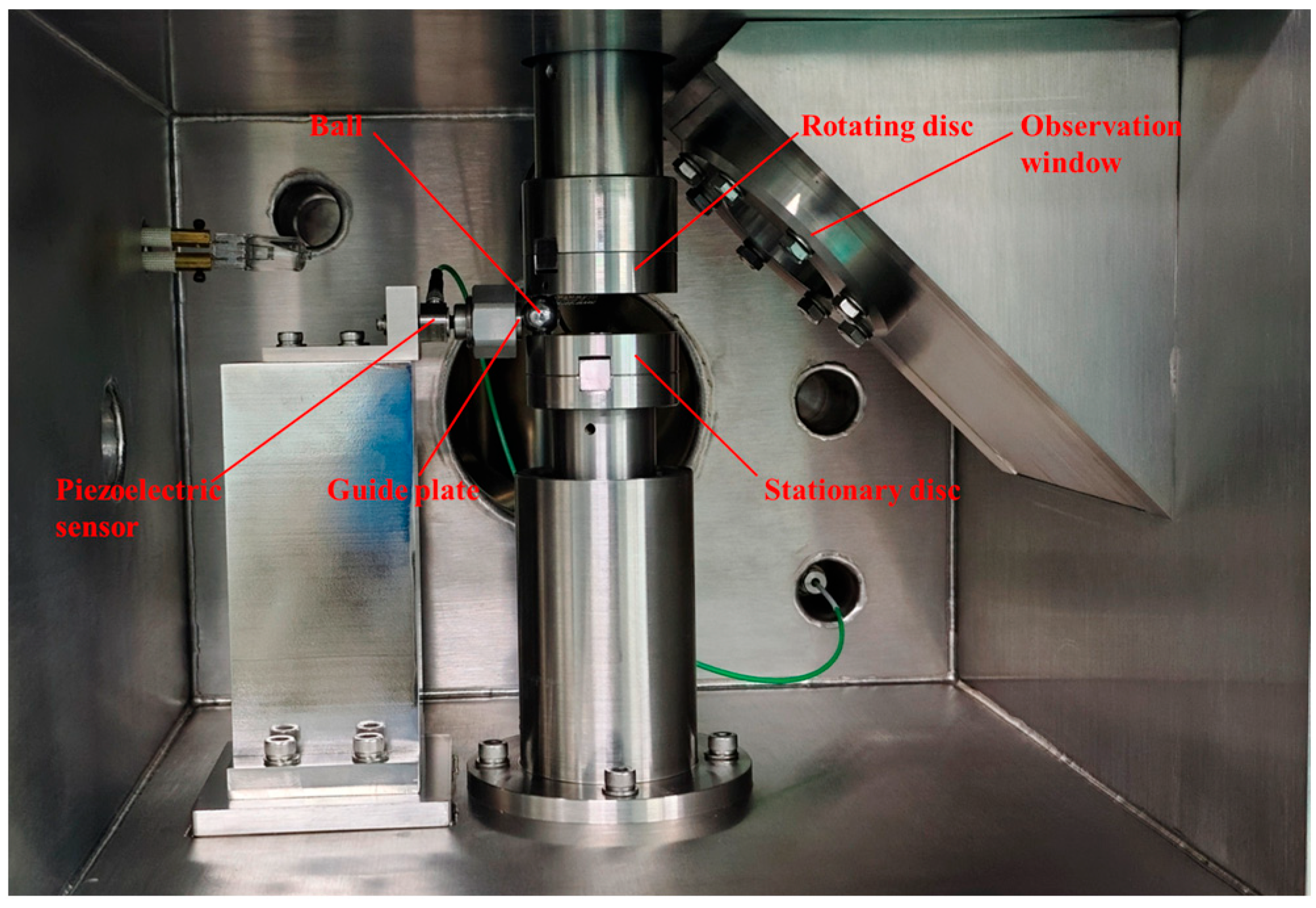
The friction force monitoring unit employs a BZ1201 piezoelectric force sensor (Qinhuangdao Beidaihe Land Technology Corp., Qinhuangdao, China) with a measurement range of 0–100 N and accuracy of 1% F.S. The piezoelectric force sensor is securely mounted on the guide plate. When the rotating disc drives the ball to perform a spiral motion, periodic collisions occur between the ball and the guide plate. The friction force signal generated by each collision is converted from an analog signal to a digital signal by the BZ2107 charge converter (Qinhuangdao Beidaihe Land Technology Corp., Qinhuangdao, China), then transmitted to the computer system for acquisition and recording. This friction measurement device is located inside the vacuum chamber and primarily consists of a guide plate, subplates, a force transmission rod, a piezoelectric sensor, and a sensor support.
The in situ morphology observation unit primarily consists of a high-resolution optical microscope and a precision displacement stage. The optical microscope is aligned with the stationary disc surface through a 45° inclined observation window on the right side of the vacuum chamber. Micrometer-level focusing and position adjustment are achieved via the displacement stage, enabling dynamic observation of friction trajectories on the stationary disc surface. Observation images are captured in real-time by a high-definition camera and transmitted to the computer system. The microscope features a 50× optical magnification, resolution better than 6 μm, and a working distance range of 65–120 mm. The integrated camera employs a color sensor with a pixel resolution of 5440 × 3648 (20 megapixels). To ensure clear imaging, a white light ring illumination source is integrated into the microscope lens, with its observation window shown in
Figure 5. The displacement stage features focusing, lateral translation, and pitch adjustment capabilities. The lateral translation has a minimum step accuracy of 0.5 μm and supports both manual and computer-controlled modes. During experiments, manual fine-tuning of the lens fore/aft position and lateral translation enables precise focusing on the sample surface.
The Raman spectroscopy detection unit primarily consists of a laser, CCD camera, filters, grating spectrometer, and excitation/collection optical path components. It is used for real-time online detection and analysis of chemical property changes in the lubricating film on the stationary disc surface and the structure of surface products formed in the friction zone during the lubrication process. The module employs a laser model MSL-DS-532-100 mW (Changchun Institute of Optics, Mechanics and Physics, Chinese Academy of Sciences, Changchun, China), emitting at 532 nm with an output power of 50 mW and automatic focusing accuracy better than 0.2 μm. The CCD camera model is ivac-316-CCD (Beijing Zhuoli Hanguang Instruments Corp., Beijing, China), with a response spectral range of 200–1100 nm and effective pixels of 2000 × 256. The grating spectrometer model is Omni-λ300i (Beijing Zhuoli Hanguang Instruments Corp., Beijing, China), with a focal length of 320 mm, a scanning step size of 0.005 nm, and a resolution better than 2.0 cm−1. This unit shares a vacuum observation window and precision displacement stage with the in situ morphology observation unit. During experiments, the laser beam enters through the observation window onto the sample surface. The displacement stage adjusts the spot position, and the Raman scattered light is collected via the same optical path and returned to the spectrometer. After spectral separation and processing, the Raman spectrum is generated and displayed in real-time for recording within the computer system.
The gas detection unit primarily employs a residual gas analyzer for real-time monitoring of lubricant dissipation and potential gaseous reaction products. The model is RGA-100 (Beijing APhoton Technology Corp., Beijing, China), with a mass detection range of 1–100 amu and a resolution better than 0.5 amu. The gas analyzer installation location is shown in
Figure 4. During the experiment, the vacuum pump evacuates the vacuum chamber. Volatile gases generated during the rotation of the bearing rolling element are distributed within the chamber and vacuum piping. To enable real-time gas detection, a bypass line is branched from the main vacuum line. The residual gas analyzer connects to this bypass via a flange interface, allowing for continuous sampling and analysis of the chamber’s gas composition.
3.3. Data Acquisition and Control Module
This system enables precise simulation and multidimensional real-time in situ monitoring of the motion of a bearing rolling element under vacuum conditions through its control software, featuring outstanding automation and integration capabilities. Prior to testing, the software interface allows for presetting of loading force, rotational speed, test duration, and one-click initiation of the vacuum pumping program, enabling rapid establishment and stable control of the test environment. During testing, the system supports real-time observation of the stationary disc surface morphology, continuous acquisition and analysis of Raman spectra, as well as online monitoring and mass spectrometry analysis of residual gases. This facilitates qualitative identification and quantitative tracking of friction chemical reaction products. All critical parameters—including applied load, rotational speed, revolutions, friction force, friction coefficient, vacuum level, and residual gas mass spectrometry data—are automatically recorded and stored within the system.
4. System Performance Verification
4.1. Functional Verification
4.1.1. Vacuum Level Verification
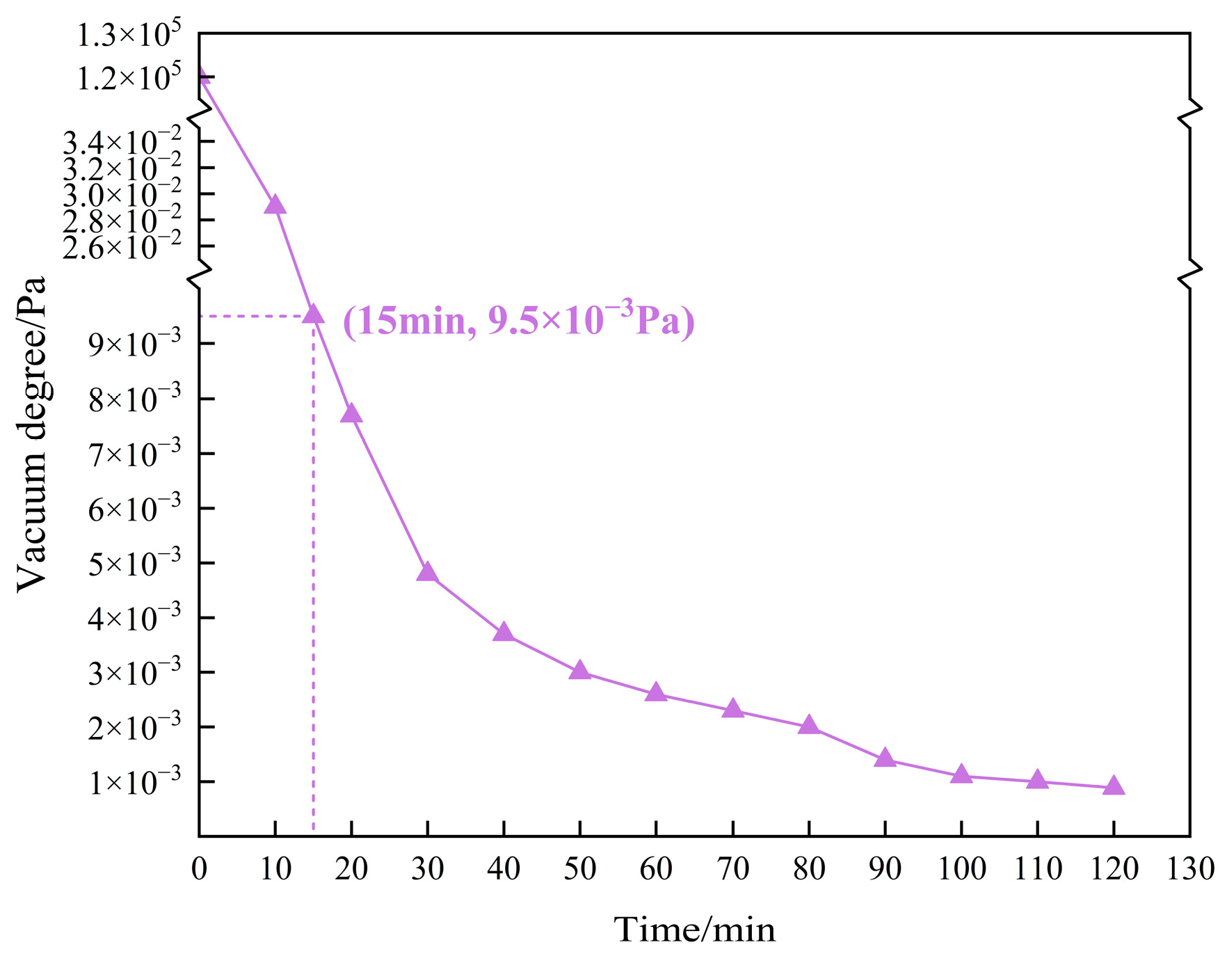
To accurately simulate the actual operating conditions of bearing rolling elements in a vacuum environment, it is necessary to verify the vacuum performance of the system. The system employs mechanical pumps and molecular pumps to evacuate the vacuum chamber, utilizing a resistive ionization vacuum gauge to monitor real-time pressure changes within the chamber. Test results are shown in
Figure 6. The system demonstrated excellent pumping efficiency and stability, rapidly achieving a vacuum level of 9.5 × 10
−3 Pa within 15 min of startup. Within one hour, it reached a high-vacuum operating state of 2.6 × 10
−3 Pa and maintained stability at the 10
−3 Pa level for the subsequent hour. These results demonstrate that the system possesses an excellent vacuum maintenance capability. It effectively simulates extreme high-vacuum conditions in space, meeting the vacuum environment requirements for space bearing testing.
4.1.2. Loading Force and Rotational Speed Accuracy Verification
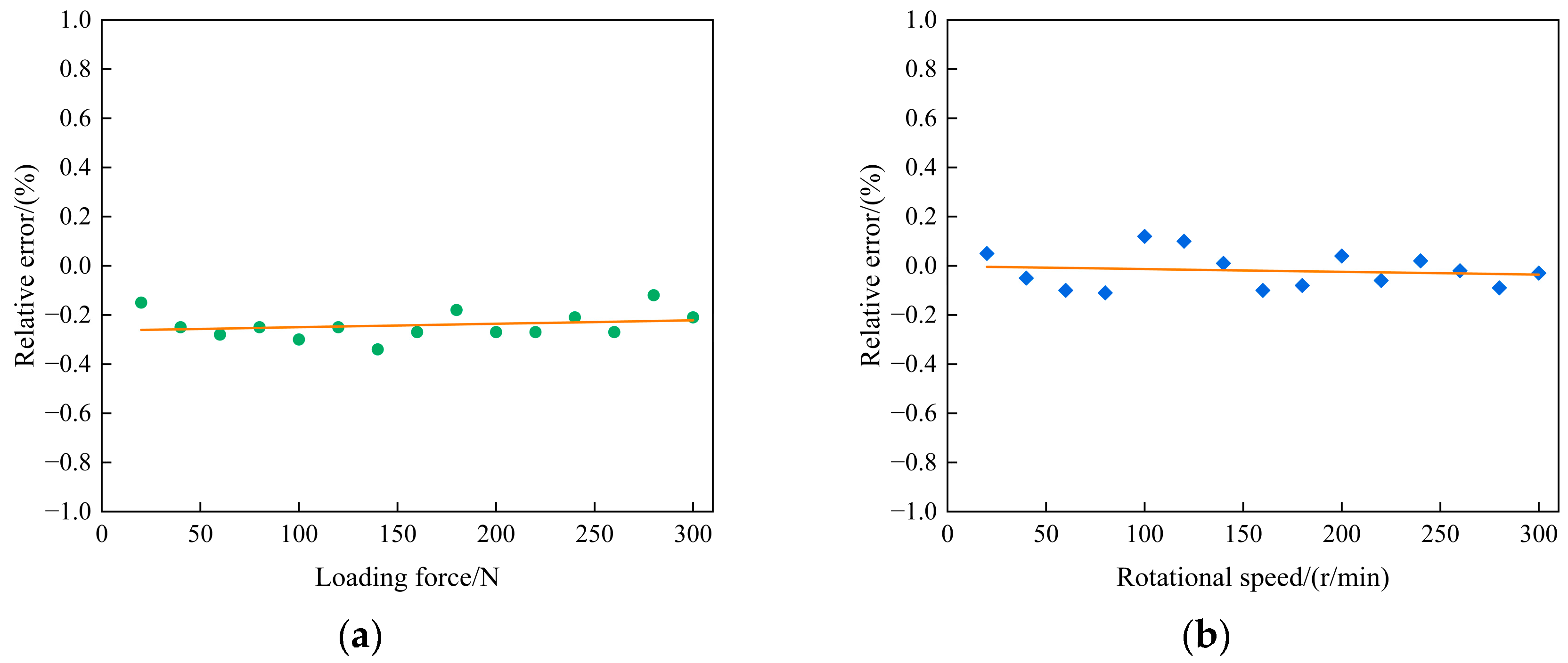
To account for potential inaccuracies in load measurement due to component alignment errors and to ensure realistic simulation of the motion of a bearing rolling element, the accuracy of both the applied load and rotational speed was verified. Load accuracy was evaluated by comparing system readings against a standard pressure sensor installed on the lower specimen holder. The load was incremented from 0 N to 300 N using the system software, with both force values recorded synchronously; the process was repeated three times, after which the data were averaged to calculate the relative error. Rotational speed accuracy was calibrated using a digital tachometer. A reflective marker was attached to the spindle, and the tachometer’s infrared probe was positioned 100 mm away. After the spindle reached a stable preset speed (1–300 r/min), the tachometer reading was recorded and compared with the system-displayed value. The average value over three experimental runs was calculated to determine the relative error.
Statistical analysis of the test data, as shown in
Figure 7, demonstrates that the system exhibits high precision and stability across the entire load range (0–300 N) and rotational speed range (1–300 r/min). The relative error at all measurement points remains within 1%. The test results validate that the system delivers high precision in both load force and rotational speed control, along with excellent dynamic response characteristics and steady-state accuracy, thereby meeting the application requirements.
4.1.3. In Situ Monitoring Module Verification
To ensure the functional reliability and collaborative effectiveness of the four core units within the in situ monitoring module—the friction force monitoring unit, in situ morphology observation unit, Raman spectroscopy detection unit, and gas detection unit—systematic functional validation experiments must be conducted on each unit.
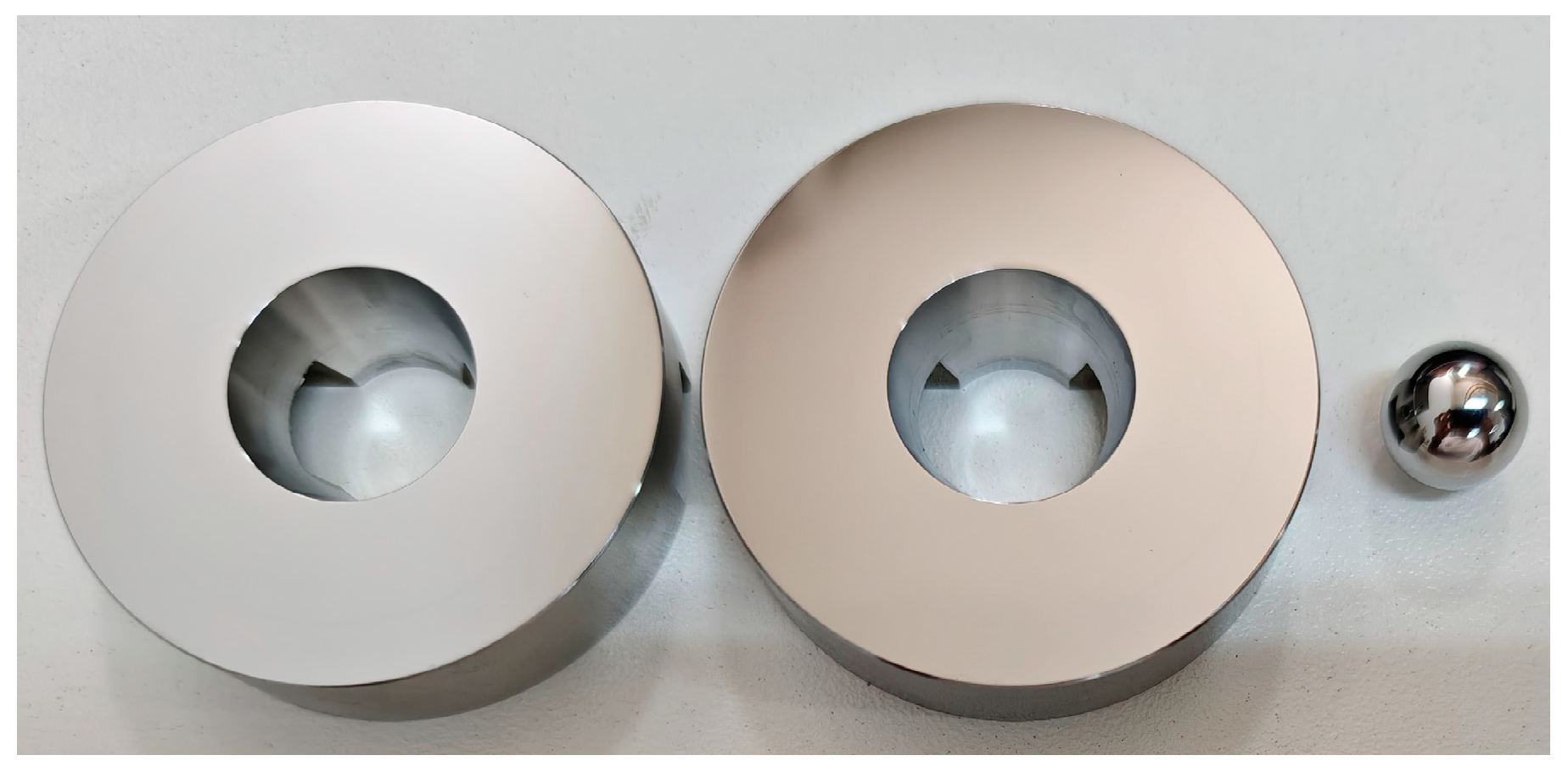
The test specimens consisted of a rotating disc, a stationary disc, a steel ball, and PAO4 lubricant; the configurations of these components are shown in
Figure 8. Both discs, made of 304 stainless steel, had an outer diameter of 50.8 mm and an inner diameter of 20 mm, while the steel ball had a diameter of 12.7 mm. The rotating and stationary discs were mounted on the upper and lower specimen holders, respectively. The steel ball, coated with a layer of PAO4 lubricant, was placed between them. The test parameters were set to 25 °C, an applied load of 100 N, and a rotational speed of 100 r/min. As the gas analyzer requires a vacuum level within 10
−3 Pa or better to detect residual gases, the chamber was evacuated until this pressure was reached before activating the motion simulation and in situ monitoring modules.
The test results are shown in
Figure 9. The average friction coefficient measured in the experiment was 0.0541, with a stable friction curve as depicted in
Figure 9a, indicating a stable friction state.
Figure 9b displays the wear morphology generated during the ball’s movement on the stationary disc, clearly revealing the wear track and debris distribution. Real-time Raman spectroscopy analysis of the PAO4 lubricant is shown in
Figure 9c. This lubricant is a synthetic polyalphaolefin oil produced by polymerizing and hydrogenating alpha-olefins. As shown in the figure, a prominent characteristic peak is observed near 1445 cm
−1. This peak corresponds to the bending vibration of the CH
2 group in the PAO4 lubricant [
31], confirming the effectiveness of the Raman spectroscopy unit in identifying the lubricant’s chemical state and molecular structure.
Figure 9d presents the residual gas mass spectrum, clearly displaying characteristic peaks for H
2, He, N
2, O
2, H
2O, and CO
2. This demonstrates the gas detection unit’s capability to accurately detect multiple volatile products. In summary, all units of the in situ monitoring module are operating normally and producing reliable data, validating the overall stability and effectiveness of the system.
4.2. Differentiation Verification
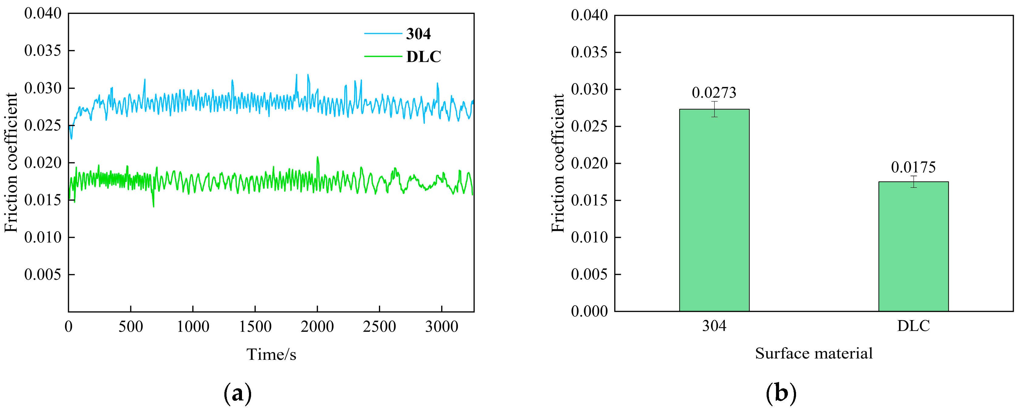
To ensure the reliability of this system in CMG bearing material research, a differentiation verification must be conducted to assess its capability to distinguish between samples with different surface materials. The experiment selected two sets of test discs with surface materials of 304 stainless steel and diamond-like carbon (DLC) as research subjects. Conducted at room temperature (25 °C), the test employed a loading force of 200 N and a rotational speed of 200 r/min. A steel ball coated with PAO4 lubricant was placed between the rotating disc and the stationary disc. The experiment was then initiated to collect friction force and friction coefficient data.
The experimental results are shown in
Figure 10. The average coefficient of friction for the 304 stainless steel test disc was 0.0273, whereas the value measured during validation of the in situ monitoring module was 0.0541, indicating a notable discrepancy. This discrepancy is primarily attributed to the combined thermal effects of increased rotational speed and applied load. As the rotational speed rises, the intensified relative motion between the ball and disc, coupled with the elevated load, enhances shear-induced heating in the contact zone. This leads to a significant temperature rise, consequently reducing lubricant viscosity. The resultant decrease in viscosity partly diminishes the internal friction of the lubricant, thereby lowering the friction coefficient. This observation is consistent with results reported by Li et al. [
27] using a ball–ring point-contact friction measurement system.
The average friction coefficient measured on the DLC-coated test disc was 0.0175. This value is close to the range of 0.007–0.013 reported in Reference [
32] for DLC coatings under vacuum. The slight deviation can be attributed to differences in coating structure and the higher load applied in our experiments.
The test results serve to demonstrate the system’s capability to distinguish frictional performance across different disc materials, which is consistent with its designed operational requirements.
4.3. Repeatability Verification
During actual testing, the time-varying nature of systematic errors leads to inconsistent results under identical experimental conditions, severely undermining the reliability of experimental data. To ensure the reliability of this system’s test results, its repeatability must be verified.
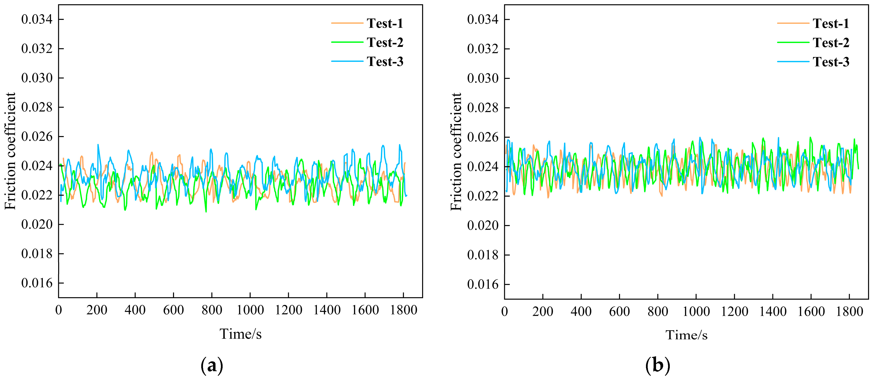
The experiment employed identical sets A and B of 304 stainless steel rotating discs, stationary discs, and steel balls. Under a load of 200 N and at a rotational speed of 200 r/min, three repetitive clamping tests were conducted on the same set of test discs, each lasting 30 min. By analyzing friction force and coefficient of friction data obtained across different clamping cycles, the relative error and standard deviation were calculated to quantify the impact of clamping repeatability on experimental reliability. This also assessed the stability of the equipment itself and the reliability of the data acquisition system.
The test results are shown in
Figure 11. The repeatability standard deviation for the two sets of test data was calculated using the Bessel formula:
In Equation (4), n denotes the number of measurements, represents the measurement value for the i-th measurement, and denotes the mean value.
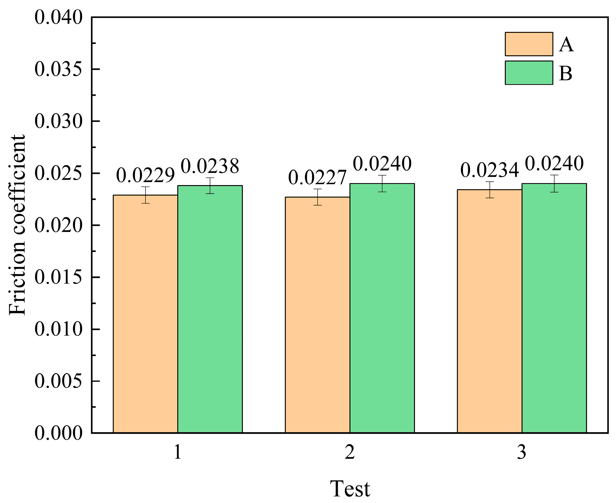
Statistical analysis of the two sets of test data, as shown in
Figure 12, reveals that the average friction coefficient for the three clamping tests of Sample A was 0.02300 with a standard deviation of 0.000361, while that for Sample B was 0.02393 with a standard deviation of 0.000116. The standard deviations for both tests were below 0.001, indicating excellent system stability and repeatability, thereby meeting all operational requirements.
Test data fluctuations stem from two primary sources: the inherent precision limitations of measurement instruments (including piezoelectric sensors and load cells), and unpredictable variations in experimental conditions and measurement processes. The combined effect of these factors contributes to the observed fluctuations in test data.
