Article

The Influence of Initial Solution Estimate Method on Efficient Boundary Element Modeling of Rolling Contact

1
School of Rail Transit, Chengdu Vocational & Technical College of Industry, Chengdu 610213, China
2
MOE Key Laboratory of High-Speed Railway Engineering, Southwest Jiaotong University, Chengdu 610031, China
3
School of Civil Engineering, Southwest Jiaotong University, Chengdu 610031, China
4
Metals and Chemistry Research Institute, China Academy of Railway Sciences Corporation Limited, Beijing 100081, China
*
Authors to whom correspondence should be addressed.
Lubricants 2025, 13(11), 508; https://doi.org/10.3390/lubricants13110508
Submission received: 15 October 2025 / Revised: 14 November 2025 / Accepted: 17 November 2025 / Published: 20 November 2025

Abstract

A novel methodology is proposed for accelerating the calculation efficiency of the boundary element modeling of rolling contact. This methodology involves the implementation of an initial solution estimate. The method is to provide the initial estimate value by means of simplifying the method, which is used for the iterative calculation of the boundary element method to solve the normal and tangential contact problems. In the normal contact problem, the normal pressure and contact patch are provided as the initial values for the iterative calculation of the boundary element method. In the tangential contact problem, the initial values for tangential stress and adhesion-slip distribution are provided. A first novel aspect is breaking the initial iteration setting of the traditional BEM, which can significantly reduce the iterations. A second novelty is that a method for determining the potential contact area is proposed to ensure the correctness of boundary element modeling without increasing the computational cost. In the following section, an analysis is conducted to ascertain the impact of the initial solution estimate method on the efficacy of boundary element modeling. The result is that efficiency increased by 69.1% of normal contact calculations, with the initial contact patch exerting the most significant influence. The efficiency of the process under investigation increased by 56.9%, and the most pronounced effect is the distribution of adhesion-slip.

1. Introduction

The railway employs the wheel–rail contact pair to bear train load and provide guidance. The manner in which the wheel–rail interface interacts directly impacts the safety, stability, and ride comfort of railway trains. The primary function of a wheel–rail system is to support substantial loads; consequently, they are typically composed of steel. Consequently, the wheel–rail interface manifests minor deformation, thus giving rise to a contact patch with an approximate area of 1 cm2. Consequently, the contact pressure may exceed 1 GPa [1]. To date, it has proven to be a considerable challenge to directly measure the behavior of wheel–rail contact in such a minute contact area. The utilization of a precise and expeditious numerical model constitutes the primary instrument for the investigation of wheel–rail contact behavior [2]. In the following models, a systematic division into three groups can be proposed: the finite element method (FEM) [2,3,4,5], the boundary element method (BEM) [6,7,8,9], and the virtual penetration method (VPM) [10,11]. The comparison of different contact methods is shown in Table 1.

1.1. The Accurate Solution

In the FEM, the wheel and rail are meshed by solid element, and their contact is treated by the penalty method. The structural deformation, the real wheel–rail contact geometry, and the material nonlinearity can thus be considered, so it is usually used for complex contact problems such as wheel–rail transient impact [12,13], local stress concentration [14], and plastic deformation-related damage problems [15,16]. However, this method generally requires several to dozens of hours to reach a resolution for a given contact case. The low computational cost of this process has further limitations when applied to practical engineering analysis.
The BEM has been widely used in the field of wheel–rail contact research, encompassing the optimization of wheel–rail profiles, engineering-oriented damage assessment, and the validation of simplified contact models [17]. The method under discussion employs the half-space assumption and concerns itself exclusively with the local contact area arising in the wheel–rail interface. This renders it considerably more computationally efficient than the FEM. One of the most renowned models is the “exact theory” proposed by Kalker [18,19]. In his theory, the contact mechanics equation is transformed into a problem that involves finding the minimum value of complementary energy. In light of the absence of an explicit solution, a robust numerical program was devised, designated CONTACT, for the purpose of resolving the convex optimization problem. The nature of this program is to discretize the potential contact area and use the BEM to iteratively solve the final solutions. The advent of numerical algorithms has led to significant advancements in the field of numerical analysis. For instance, Vollebregt [20,21,22] has proposed a methodology that expedites Kalker’s method by employing the conjugate gradient (CG) approach as an alternative to the Newton–Raphson method. Another well-known BEM was proposed by Polonsky and Keer [23]. In their method, they used multi-level multi-summation algorithms (MLMS) to speed up the solution of the elastic displacement matrix, and the combined conjugate gradient (CG) method to speed up the iterative solution process. The rationale behind this phenomenon is that full matrix–vector products necessitate n2 operations, with n the number of discretization elements, whereas fast algorithms require only nlog (n) to work.

1.2. The Simplified Solution

Though large improvements in computational efficiency have been achieved for the BEM, it remains regarded as inefficient for the purpose of solving problems related to wear prediction and vehicle–track dynamics, which necessitates the resolution of millions of contact cases. The fundamental constraint imposed on the BEM by its nature is the requirement for iteration. Consequently, in the context of normal contact problems, certain researchers have proposed the non-iterative VPM, whereby the wheel and rail are permitted to rigidly penetrate, and the effect of elastic deformation on contact patch size is simply represented by the reduction factor. Kik and Piotrowski [24,25] proposed an approximate method for determining the initial contact area by using a constant reduction factor (=0.55), and assumed that the normal pressure distribution along the lateral direction is proportional to the longitudinal length of the contact patch. Ayasse and Chollet [26] also used the VPM to develop the model STRIPES. The model under consideration divides the contact patch into multiple strips along the rolling direction. Each strip is located at the center of the corresponding equivalent ellipse, and the contact pressure on the strip is calculated based on the Hertz theory. In contrast to the KP method, it employs a curvature-related variable at the contact point as opposed to the utilization of an empirical constant value. Subsequent to the publication of these two pioneering works, several scholars attempted to enhance the accuracy and analytical content of their research. Liu et al. [27] pioneered an extension of the KP method, incorporating the yaw angle of the wheelset as a critical element. This innovation enhanced the method’s precision, particularly in quantifying contact pressure. The researchers’ approach entailed a meticulous consideration of the variation in profile curvature across the contact patch, a significant advancement in the field. Sun et al. [28] proposed a modified KP method that is more robust on some special contact cases by considering the relationship between the elastic deformation of a line and the normal pressure distribution. Zhu et al. [29] modified the STRIPES to enhance the contact results by recalculating the virtual penetration value. This idea is more accurate if the force is given as a priori when a static contact case arises. Recently, An and Wang [30] proposed a model called INFCON that combines the VPM and the strip-like Boussinesq’s integral. A novel VPM is proposed to delineate the longitudinal and lateral boundaries of the contact patch. Subsequently, the strip-like Boussinesq’s integral is utilized to ascertain the normal pressure. A significant improvement of accuracy is reported in terms of contact shape and pressure distribution. However, it should be noted that the aforementioned fast algorithms are founded upon a series of assumptions and are merely approximate models. Consequently, they exhibit deficiencies in certain exceptional non-Hertz cases.
On the tangential contact problem, the most widely employed rolling contact model is the simplified theory proposed by Kalker [30]. It is assumed that the contact stress in the contact patch is only related to the elastic displacement in the corresponding direction and that it is linear. Based on this, the expression of the flexibility coefficient in three directions is obtained. The tangential stress distribution on each strip is recursively obtained from the front edge of the contact patch, and the required creep force and torque are obtained by integration. A numerical algorithm FASTSIM is developed. Since the accuracy of FASTSIM will be affected by mesh size, Vollebregt improved it to have second-order accuracy and updated the mesh generation method, to reduce the dependence of FASTSIM on mesh size [31]. However, the fundamental purpose of FASTSIM is to furnish precise contact forces for the purpose of vehicle dynamics. Consequently, the introduction of certain erroneous assumptions is inevitable. The model is inaccurate for solving local tangential contact solutions. Therefore, Sichani et al. [32] proposed an alternative algorithm named FaStrip by extending Kalker’s strip theory. Furthermore, in order to apply it to non-Hertzian contact, it is necessary to use equivalent ellipse [25,33] or local ellipse [26] to change the contact stiffness based on the ellipse shape to improve the calculation accuracy.
In summary, the FEM is difficult to use in engineering applications due to low computational efficiency. The simplified algorithm based on the VPM needs no iterations, whereas the results are only approximate for employing a variety of assumptions. The half-space-based BEM appears to be a promising solution in achieving a balance between computational accuracy and efficiency. However, further enhancement to its computational efficiency is necessary to meet the requirements for mass engineering computations.

1.3. The Purpose of This Paper

An aspect that is not well elaborated in this reference is the initial estimate for the BEM. It is imperative to note that this estimation incorporates two indispensable factors. Firstly, it is essential to ascertain a reasonable potential contact area that should be sufficiently extensive to encompass the actual contact area. Secondly, it is crucial to consider the initial contact area and pressure to initiate the iteration of the BEM calculation. For the first factor, the determination of potential contact usually depends on the researchers’ computation experience and its size is overestimated to avoid the abortion of continuous computation in the engineering analysis. In the second factor, a common approach is to assume the entire potential contact area as the initial contact patch and that contact pressure is constant with a small value on normal contact, while on tangential contact it is assumed that the whole contact patch is an adhesion zone and that the tangential stress is set to zero. These two factors limit the speed of computation due to redundant iterations.
In this paper, we propose an initial estimate approach for accelerating boundary element modeling of wheel–rail contact (Figure 1). The model utilizes a simplified contact model to evaluate contact patch and pressure, which is employed as an initial estimate for the BEM. It is thus possible to determine the potential contact area automatically, and to reduce iterations by a significant amount.
This paper is organized as follows: In Section 2 and Section 3, we propose a methodology for the efficient modeling of wheel–rail normal and tangential contact and explain how to improve the computational efficiency of the BEM. Section 4 presents the numerical results of the new method, and its effectiveness is demonstrated through simple Hertzian contact conditions. The main influencing factors are analyzed using complex non-Hertzian conditions. Section 5 concludes.

2. Methodology of Initial Estimate on Normal Contact

This section proposes a methodology for the efficient boundary element modeling of wheel–rail normal contact. The model under consideration combines a simplified contact model and a BEM. For a wheel–rail system with given track conditions, the contact geometry parameters of wheel–rail contact are determined by the trace method [34], which are basic parameters of contact. Because the material properties of the wheel and rail are similar, they are regarded as the same material in this paper, so that normal and tangential problems can be decoupled. In the event of these materials being regarded as entities characterized by distinct properties, it is imperative that they are subjected to iteration by the Panagiotopoulos method. This is requisite in order to achieve the desired coupling of normal and tangential contact.

2.1. Iterative Calculation of Normal Contact Using BEM

For a normal contact problem, there is a relation among penetration δ , geometry gap g , and normal elastic deformation μ n as follows:
δ = μ n + g
Thus, the normal contact problem is to determine the contact region C and the contact conditions are satisfied as follows:
in   exterior   E : δ > 0 , p n = 0 in   contact   C : δ = 0 , p n 0
There is no explicit solution for Equation (1), because the deformation μ n is associated with the pressure throughout the unknown contact area. Therefore, the BEM is utilized in order to discretize the problem, determine the potential contact area by dividing several rectangular elements, and iteratively solve each element to satisfy the boundary conditions Equation (2).
Thus, determining potential contact area is very important. Should the area be considered excessively large, then this will result in an increase in the calculation cost. It is important to note that a sample size of this magnitude is not sufficient to ensure the attainment of precise results. However, determining potential contact area often depends on the experience of researchers. In this paper, a methodology is proposed for determining the potential contact area.
Lateral boundary y L , R of a potential contact area is determined by initial penetration δ 0 (penetration amount calculated by the Hertz contact theory at a rigid contact point) and lateral geometric gap f ( y ) , while the longitudinal geometric gap is assumed to be a parabolic of longitudinal curvatures A :
x L , R : A x 2 δ 0
y L , R : f ( y ) δ 0
Then, the potential contact area ( x , y ) is divided by an iterative calculate grid ( m x , m y ) for the BEM calculation. In this paper, the classical method known as the Extended CG method [23] is employed. This method was developed for the purpose of addressing quadratic optimization problems with linear inequality constraints. The determination of the contact area is made according to the contact pressure in the iterative process. Consequently, in terms of the contact area, there is no requirement for outer iteration. Another advantage of the Extended CG method is that it is a simultaneous or explicit iterative method.
In a conjugate gradient and quantities μ n solution including a convolution calculation of a matrix, we consider the DC-FFT method [35] to accelerate computational efficiency.
However, in the calculation it sets a potential contact value close to zero, and is distributed in the whole rectangular potential contact area (w/o initial estimate), which significantly reduces computational efficiency. In this paper, an approximate initial solution is provided as an input. This is achieved by calculating the contact area and normal pressure using simplified models. These are then re-meshed into the potential contact area grid. The normal BEM is then used to solve the exact solution based on this.

2.2. Initial Estimate Using Simplified Normal Contact Models

In normal contact, we need a simplified algorithm to calculate initial normal pressure and contact patch for the BEM. In this section, we provide a concise overview of three simplified normal contact models that are employed for the initial estimate, which is shown in Table 2. These models vary from Hertzian to non-Hertzian in the contact patch and from low to high accuracy in contact pressure calculation, but from fast to slow in computational speed.

2.2.1. Hertz Contact Theory

The first initial estimate approach we consider is Hertz theory. It was proposed by Hertz and has been widely used up to now for its analytical and accurate elliptical solution.
This method assumes that the contact patch is elliptical, so the normal contact pressure distribution p n x , y in the contact area can be obtained by Hertz parameters, which have no need to divide the initial estimate grid ( n x , n y ) . In order to apply it to accelerate the Extended CG algorithm, the pressure is distributed to the iterative calculate grid ( m x , m y ) by the following formula [36]:
p n ( x I , y I ) = p n max ( 1 ( x I / a ) 2 ( y J / b ) 2 ) 1 / 2 , ( I 1   ~   m x , J 1   ~   m y )
There are three parameters in this formula: the long and short half-axis length of the elliptical patch a , b , and the maximum contact pressure p n m a x at the elliptical center. The specific calculation is in Reference [36].

2.2.2. Kik–Piotrowski’s Approximate Method

Then we considered an approximate non-Hertz contact model, i.e., KP’s method [24]. Similarly, this method first needs to determine the contact area. Since the length of the non-Hertzian lateral and longitudinal contact area cannot be directly determined, it is necessary to first calculate the contact area boundary by discrete coordinates in the initial estimate grid ( n x , n y ) . The length of the longitudinal contact area still follows the Hertz hypothesis [24]:
g ( y j ) = ε k p δ f ( y j ) 0 , ( j 1   ~   n y )
a ( y j ) 2 R g ( y j ) , ( j 1   ~   n y )
In the formula, ε k p   =   0.55 is the proportional coefficient and R is the contact radius.
To simplify the calculation of contact pressure, it is assumed that the lateral normal pressure distribution is proportional to the longitudinal length of the contact area. Thus, we can obtain the contact pressure distribution in the initial estimate grid ( n x , n y ) [24]:
p n ( x i , y j ) = p n ( y j ) a 2 ( y j ) x i 2 , ( i 1   ~   n x , j 1   ~   n y )
p n ( y j ) p n max = a ( y j ) a 0 , ( j 1   ~   n y )
where a 0 is the length of the longitudinal half axis at y = 0 , since the elastic deformation at the contact point is equal to the penetration. Then the contact pressure can be redistributed in the subsequent iterative calculate grid ( m x , m y ) to accelerate the Extended CG algorithm.

2.2.3. An–Wang’s Model (INFCON)

We further employed a more accurate simplified non-Hertz contact model called INFCON [37].
This method combines the VPM and Boussinesq’s integral., which is similar to Kik–Piotrowski’s model, but the difference is that the author proposes the attenuation coefficient χ to scale the potential contact area instead of using empirical values ε k p , which can ensure an accurate Hertz contact solution and better adapt to non-Hertz contact [37]:
g ( y j ) = χ δ f ( y j ) 0 , ( j 1   ~   n y )
a ( y j ) = a e g ( y j ) χ δ , ( j 1   ~   n y )
χ = n e 2 B e r e ( A + B e )
The formula contains the Hertz parameters n e , r e and the lateral curvature B e obtained by elliptic integral. a e is the equivalent elliptical longitudinal half-axis length of the contact area.
Furthermore, the deformation can be solved via the Boussinesq’s integral and the pressure distribution is assumed to be symmetric and elliptic about the x = 0 [37]:
p n ( x i , y j ) = p n ( 0 , y j ) 1 ( x i / a ( y j ) ) 2 , ( i 1   ~   n x , j 1   ~   n y )
The contact pressure can be redistributed in the subsequent iterative calculate grid ( m x , m y ) to accelerate the BEM contact algorithm.

3. Methodology of Initial Estimate on Tangential Contact

Following the attainment of normal contact results, the tangential contact problem can be further resolved by the subsequent calculation of tangential stress distribution in the contact patch, adhesion, and slip area distribution. As with the normal contact process, the initial solution is obtained by means of the simplified algorithm.

3.1. Iterative Calculation of Tangential Contact Using BEM

Similarly to normal contact, for a tangential (micro-slip) contact problem, there are the following geometric relationships:
s τ = ω τ + μ ˙ τ , τ = ( x , y )
Among them, s τ is the tangential sliding displacement difference and ω τ is the rigid slip. The dot denotes a material (particle-fixed, Lagrangian) time derivative. The tangential contact conditions in the adhesion and slip areas H and S are satisfied as follows:
in   adhesion   H : | s τ | = 0 , | p τ | g in   slip   S : | s τ | > 0 , | p τ | = g , s τ / | s τ | = p τ / | p τ |
E.A.H Vollebregt [38,39] proposed a special Gauss–Seidel method based on convex programs to solve the tangential contact problem, called ConvexGS. The idea of the solver is to generate a sequence of feasible points with decreasing function values by updating a sub-vector each time. It is discretized using a “previous time instance” t 0 , with Δ t   =   t t 0 :
s τ = ω τ + ( μ τ μ τ ) / Δ t , τ = ( x , y )
μ τ is the current displacement difference in two contacting particles and μ τ is the same particles one time step earlier, at the position where they resided at time t 0 .
The traditional algorithm assumes the contact patch is all adhesion area, and it also assumes a potential pressure close to zero without an initial estimate (w/o initial estimate). We provide an approximate initial solution as an input: the adhesion-slip distribution and tangential stress calculated by simplified models are re-meshed into the potential contact area grid, and then the normal BEM is used to solve the exact solution based on this.

3.2. Initial Estimate Using Simplified Tangential Contact Models

Similarly to the normal contact process, the initial solution is obtained by the simplified algorithm. Here we consider two typical methods: Kalker’s simplification theory [30] and Sichani–Enblom–Berg’s method [32], which are shown in Table 3.

3.2.1. Kalker’s Simplification Theory and Its Numerical Algorithm

Kalker’s simplified theory [30] assumed that the displacement of a point on the contact surface is only related to the surface pressure acting on this point. Then, the numerical algorithm FASTSIM is developed, which assumes the contact patch is elliptical, consisting of several strips along the rolling direction, and each strip is divided into several rectangular units. For steady rolling, the tangential force of the contact patch at the leading edge of the rolling is zero, and so the distribution of the tangential stress in the strip can be obtained by the negative increase in the increment to the x axis:
δ q x i = ν x L 1 ϕ L 3 y j d x i δ q y j = ν y L 2 + ϕ L 3 x i d y j
where ν x , ν y , and φ are longitudinal, lateral creepage, and spin, respectively. L 1 , L 2 , and L 3 are the flexibility coefficient in the longitudinal, lateral, and normal directions. Considering the Coulomb friction law, if the trial pressure satisfies the tangential boundary criterion, then the point x     d x is located in the adhesion area and its longitudinal and lateral tangential stress is as follows:
q x i ( x i d x i ) = q x i ( x i ) + δ q x i q y j ( x i d x i ) = q y j ( x i ) + δ q y j
Otherwise, the point is located in the slip area and its tangential stress is as follows:
q x i ( x i d x i ) = δ q x i g ( x i , y j ) δ q x i 2 + δ q y j 2 q y j ( x i d x i ) = δ q y j g ( x i , y j ) δ q x i 2 + δ q y j 2
The tangential boundary satisfies the Coulomb law g = f p n friction coefficient f in the formula.

3.2.2. Sichani–Enblom–Berg’s Numerical Algorithm

Similarly to FASTSIM, the FaStrip algorithm is also based on the assumption of elliptical contact patch [32], but the strip in the FaStrip does not need to be further divided into rectangular elements. Thus the tangential stress of the adhesion area can be calculated by the following formula.
q x i ( x i , y j ) = g a 0 [ κ a ( y j ) 2 x i 2 κ ( a ( y j ) d ( y j ) ) 2 ( x i d ( y j ) ) 2 ] q y ( x i , y j ) = g a 0 [ λ a ( y j ) 2 x i 2 λ ( a ( y j ) d ( y j ) ) 2 ( x i d ( y j ) ) 2 ]
In the formula, κ ,     κ ,   λ , and λ are dimensionless coefficients. d ( y ) is half the length of the slip area in each strip. In this way, the pressure distribution of the adhesion area is obtained. For the slip area, the FaStrip algorithm is solved by the FASISIM algorithm.
As previously stated, both the FASTSIM and FaStrip algorithms are based on the elliptical contact patch. It is important to note that these algorithms are not applicable to non-Hertzian contact conditions. Consequently, non-elliptic adaptation methods must be employed to modify them appropriately, such as the local ellipse method [39]. The core is to make the non-Hertzian contact patch equivalent to an ellipse, and to change the flexibility coefficient based on the ellipse in the algorithm.

4. Results and Discussions

In this section, the initial estimate method is programmed by MATLAB 2024b, typical Hertz and non-Hertz conditions are selected to prove the effectiveness of the method, and which factor is more important for reducing iterations is discussed.

4.1. The Influence of Initial Estimate on Normal Contact

4.1.1. Performance for Hertz Contact

The Hertzian contact case is investigated in this section. The longitudinal and lateral curvatures of Hertzian contact A = 0 . 001   mm 1 and B = 0 . 005   mm 1 are considered. The materials of two contacting bodies are assumed as steels, with E = 206 GPa and v = 0.28.
In this case, we are only concerned with the effect of the initial estimate using INFCON. In order to perform a boundary element analysis, the geometric gap should be given, being expressed by the following formula:
f ( x , y ) = A x 2 + B y 2
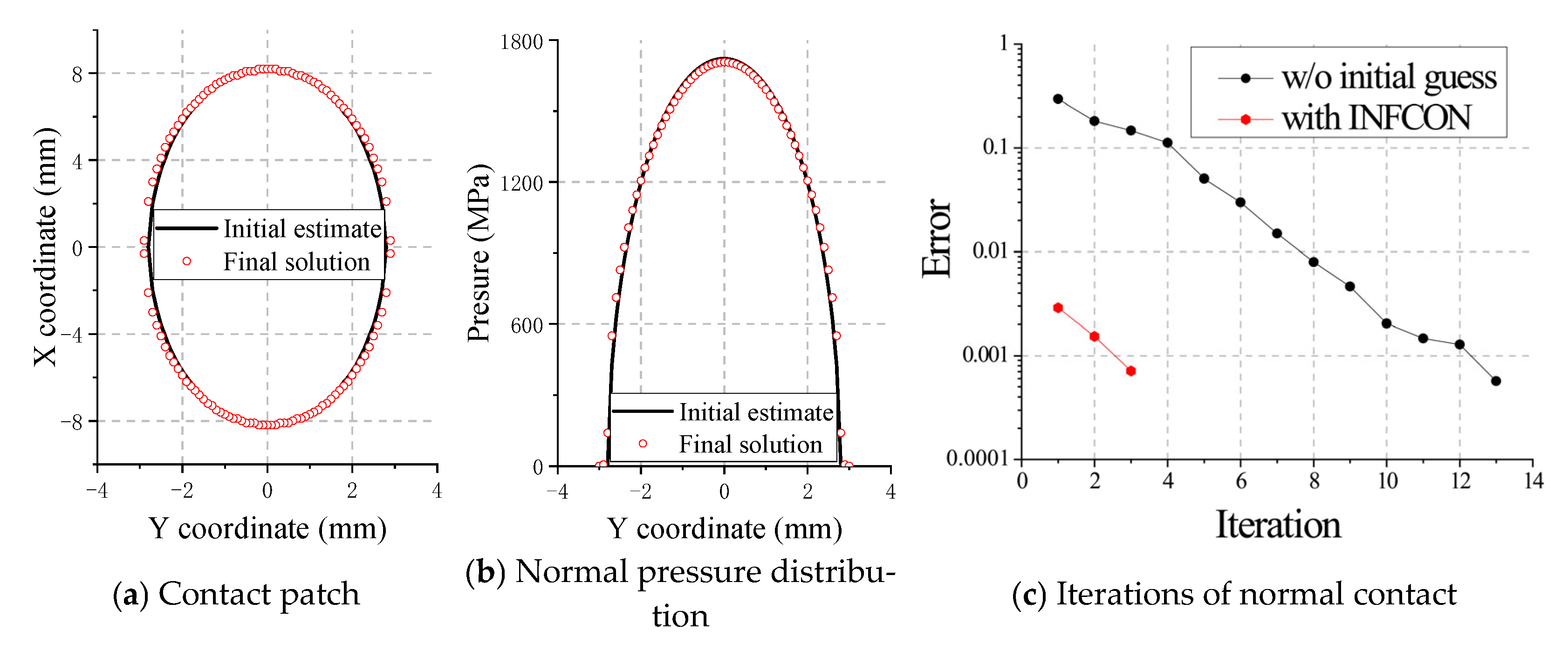
Figure 2 shows the influence of the initial estimate on normal contact under the penetration of 0.1 mm, including contact patch shapes, pressure distribution, and iterations. In this case, an error tolerance of 1 × 10⁻³ is used. The solution from the Extended CG algorithm without an initial estimate (w/o initial estimate) is used as a comparison. It is evident that the initial estimated solution by INFCON for contact patch shape and pressure distribution is highly congruent with the final solution, exhibiting an error margin of 2.9 × 10⁻³. It is evident that the iteration is considerably reduced from 13 to 3 in comparison to the solution that does not incorporate an initial estimate.
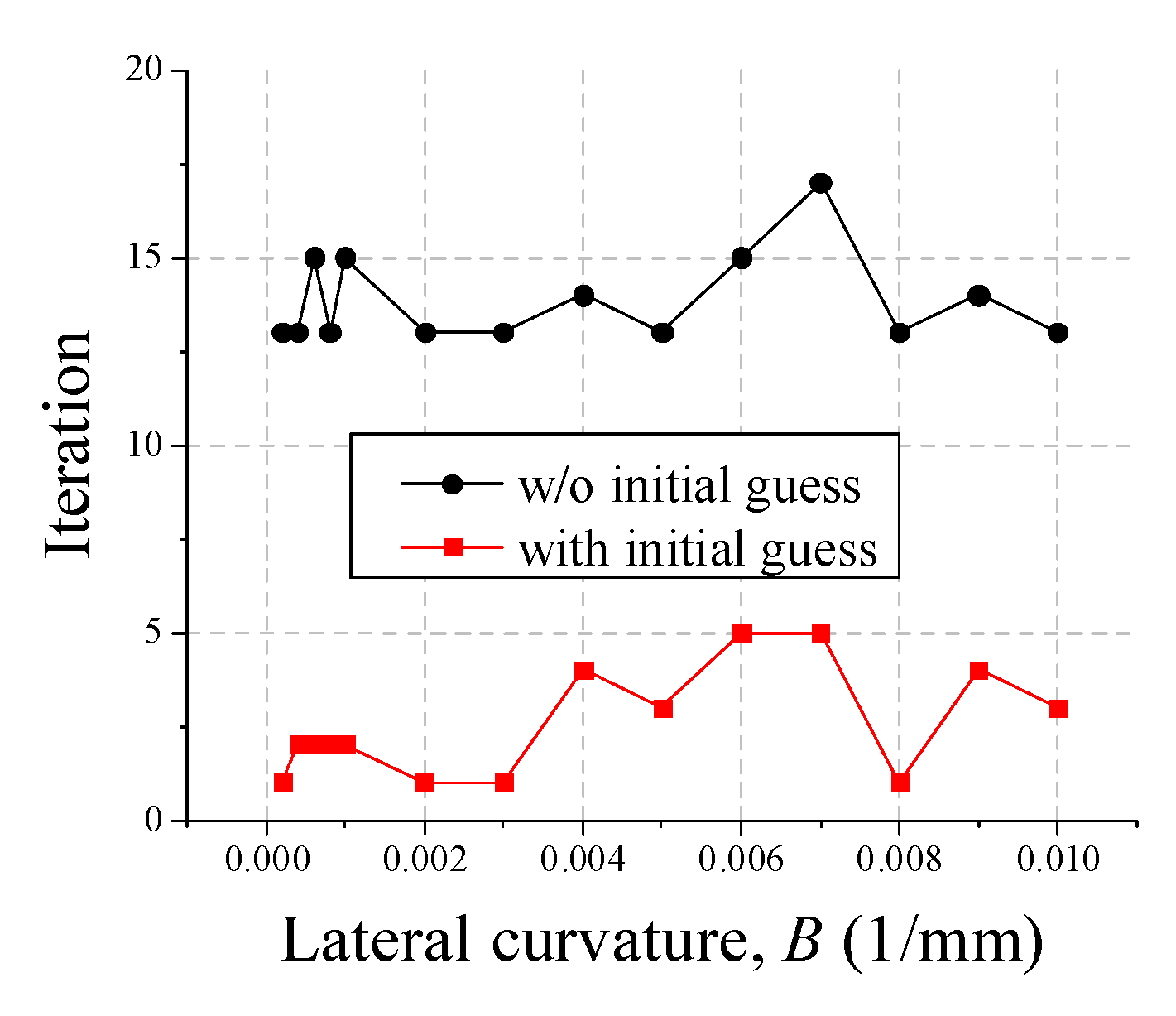
Figure 3 compares more Hertz contact cases with A = 0.001   m m 1 and increasing lateral curvature B from 2 × 10⁻⁴ to 1 × 10⁻² mm−1. The effectiveness and robustness are thus evaluated when the contact cases vary dramatically. In these cases, it can be seen that, for the solution without an initial estimate, the number of iterations is maintained at 13–17. In comparison, the number of iterations is maintained at 1–5 by using the INFCON calculation with the initial estimate, which significantly reduces the number of iterations.

4.1.2. Performance for Non-Hertz Contact of Wheel and Rail

Furthermore, we consider more complex non-Hertzian contact between the wheel and rail. The standard wheel–rail profile combinations of S1002CN and CN60 are employed, which are widely used in Chinese high-speed railways. The nominal rolling radius is 460 mm, and the yaw angle of the wheelset is ignored.
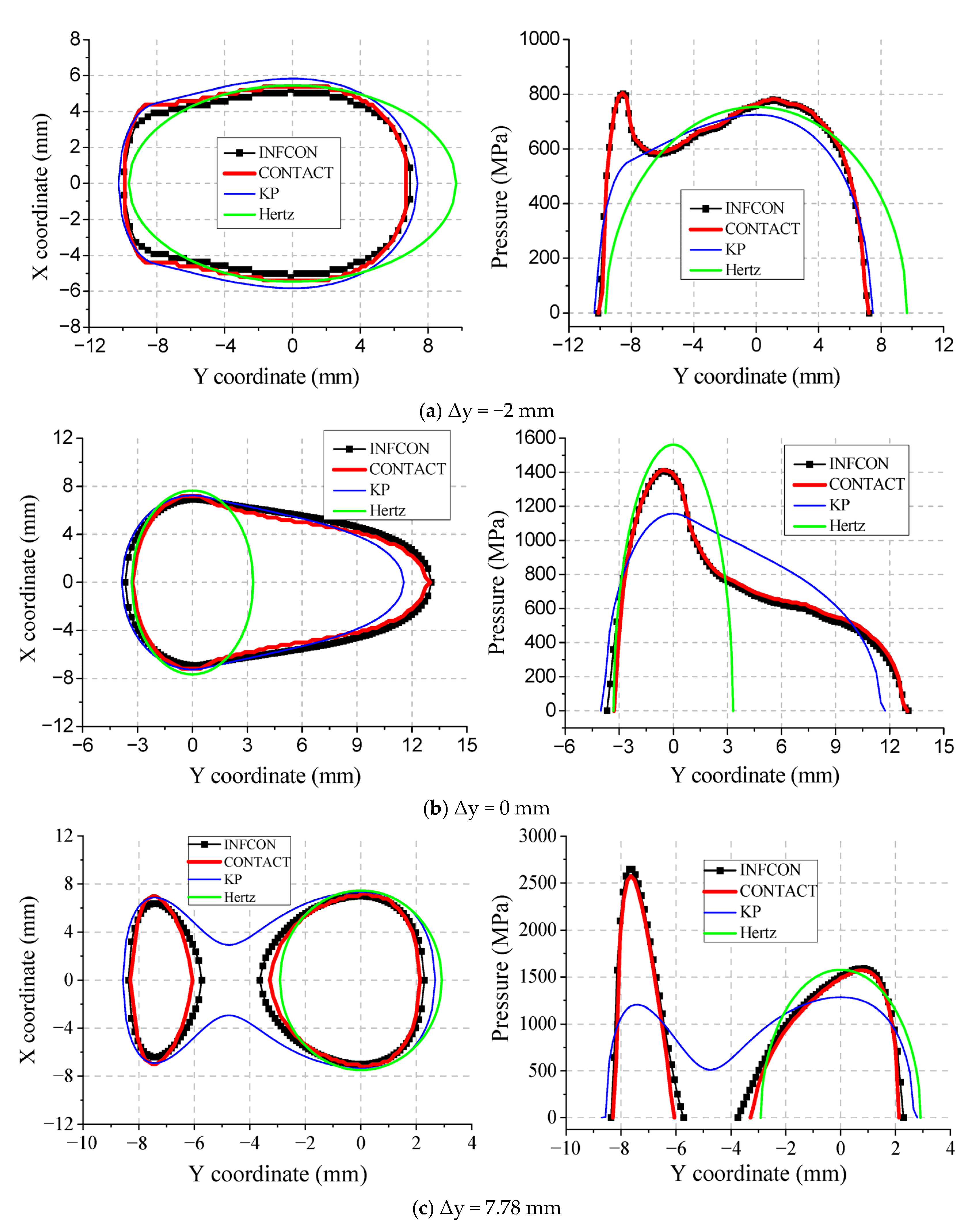
We select three typical cases with lateral wheelset displacements of −2, 0, and 7.78 mm. Since we focus on contact modeling applied to vehicle–track dynamics that uses penetration as an input, the input penetration for each contact case is obtained under the contact force of 83.3 kN. Figure 4 presents the contact patch shape and laterally distributed pressure for three lateral displacement Δy cases. The results are predicted by three simplified contact models and the exact solution CONTACT. The three contact cases under consideration are archetypal examples of wheel–rail contact, exhibiting a range of elliptical characteristics from closely elliptical to highly non-elliptical, and from one-point contact to two-point contact. The accuracy of the three simplified contact models (Hertz, KP, and INFCON) vary from low to high. Therefore, they are appropriate for investigating the effect of the initial estimate on boundary element contact modeling.
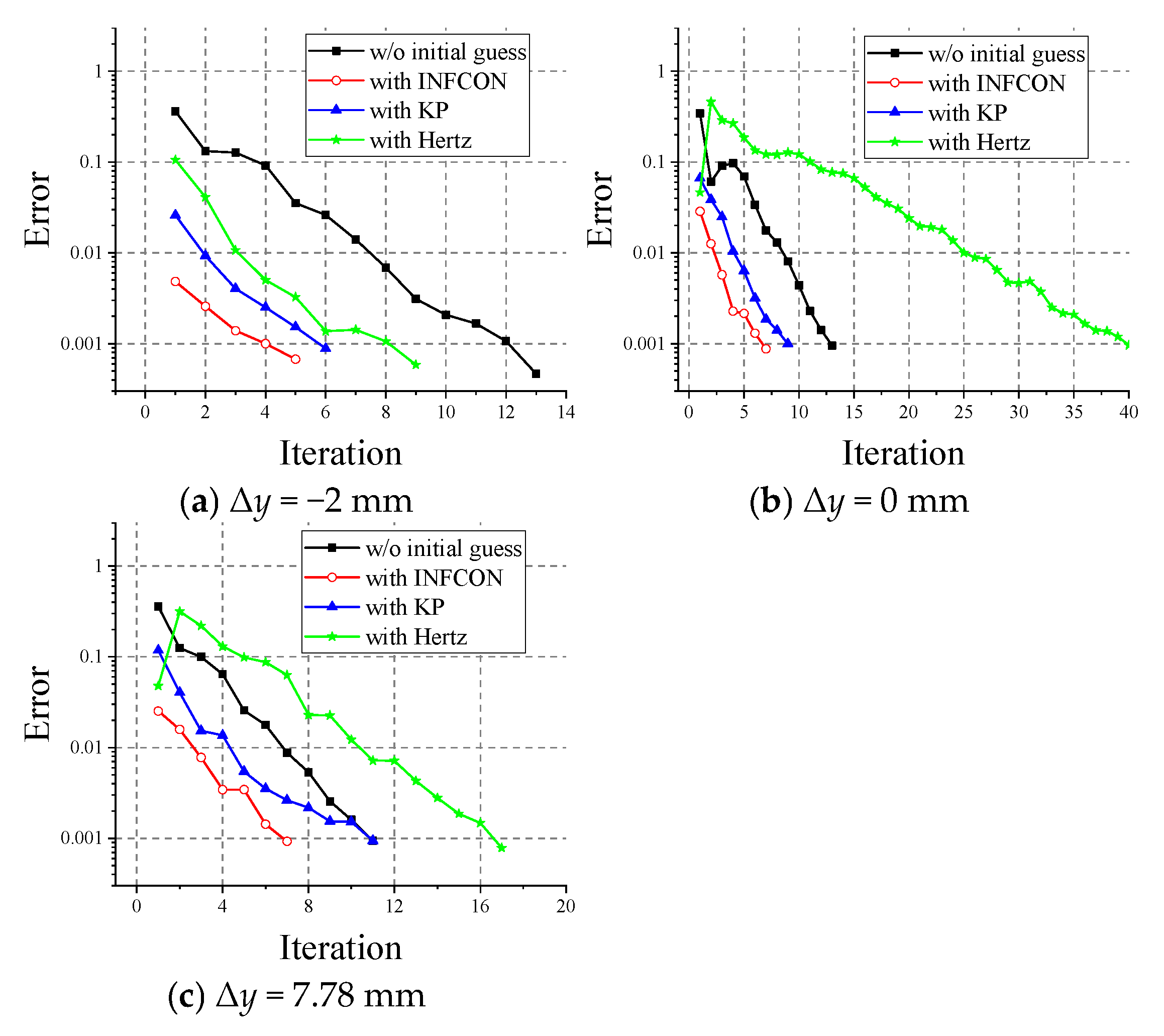
For the three cases, Figure 5 compares the iteration from four contact models with or without an initial estimate. The convergence error is set as 1 × 10⁻³. It has been demonstrated that the accuracy of the initial estimate has a significant impact on the subsequent iterations. For first case Δy = −2 mm, the iteration is reduced from 13 to 9, 6, and 5 by using Hertz, KP, and INFCON, respectively. From Figure 4a, we can see that the contact patch shape are similar for the three simplified contact models and the reference, while their contact pressures are different. This means the iteration is not very sensitive to the accuracy of the initial estimate pressure but is sensitive to the contact patch shape. This may be because the predicted pressure after initial contact patch shape estimation will become close to the accurate solution, as plotted in Figure 5a. As for the latter two cases in Figure 5b,c the performance of Hertz is poor, even worse than the solution without an initial estimate. The reason is that its predicted contact patch shape is greatly different from the reference shown in Figure 4. This viewpoint is corroborated by the analogous performance of INFCON and KP, which exhibit comparable contact patch shapes despite disparate pressures.
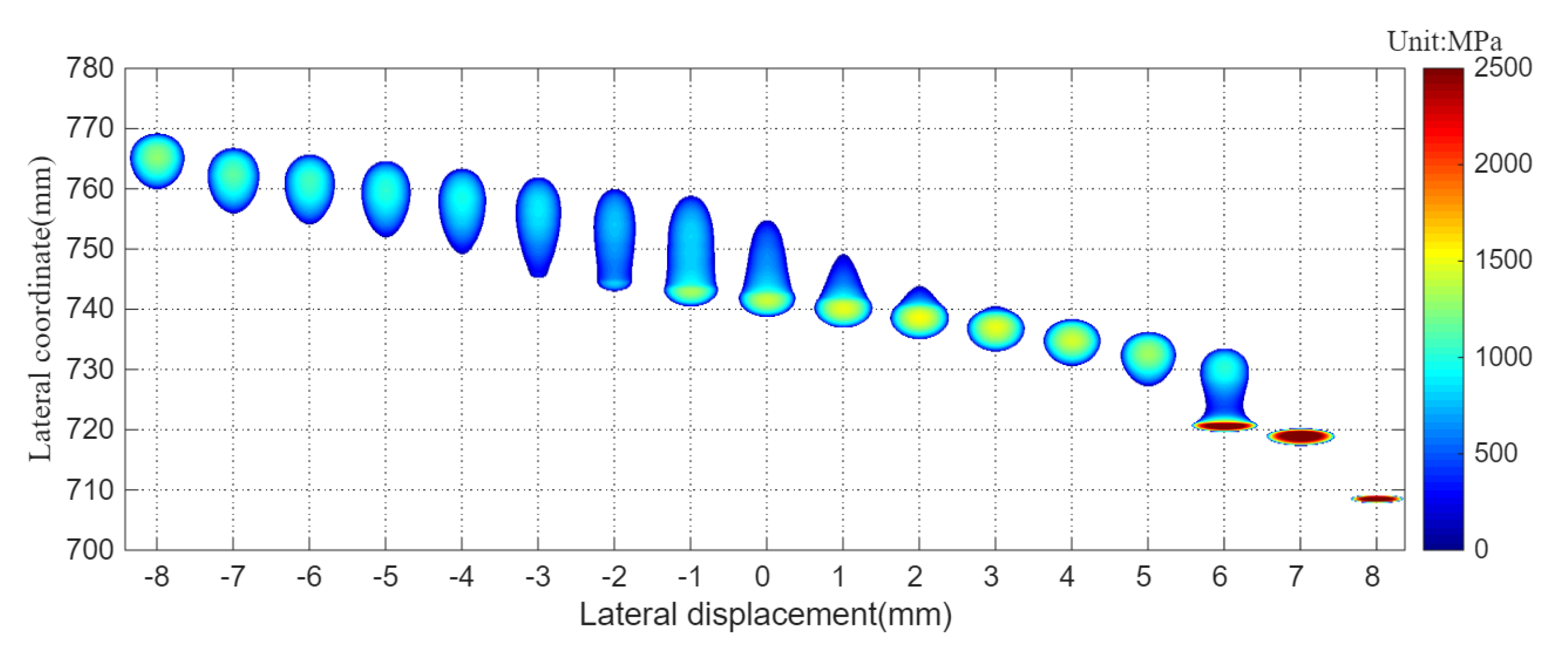
To verify the conclusion, more wheel–rail contact cases are investigated in the following, to test the effectiveness of the proposed method. As illustrated in Figure 6, the variation in wheel–rail contact patch shapes and pressure distribution by CONTACT under lateral displacements ranges from −8 to 8 mm, with an increment of 1 mm. It can be seen that the highly non-elliptic contact is reflected in the range of −3 to 2 and 5 to 7 lateral displacements.
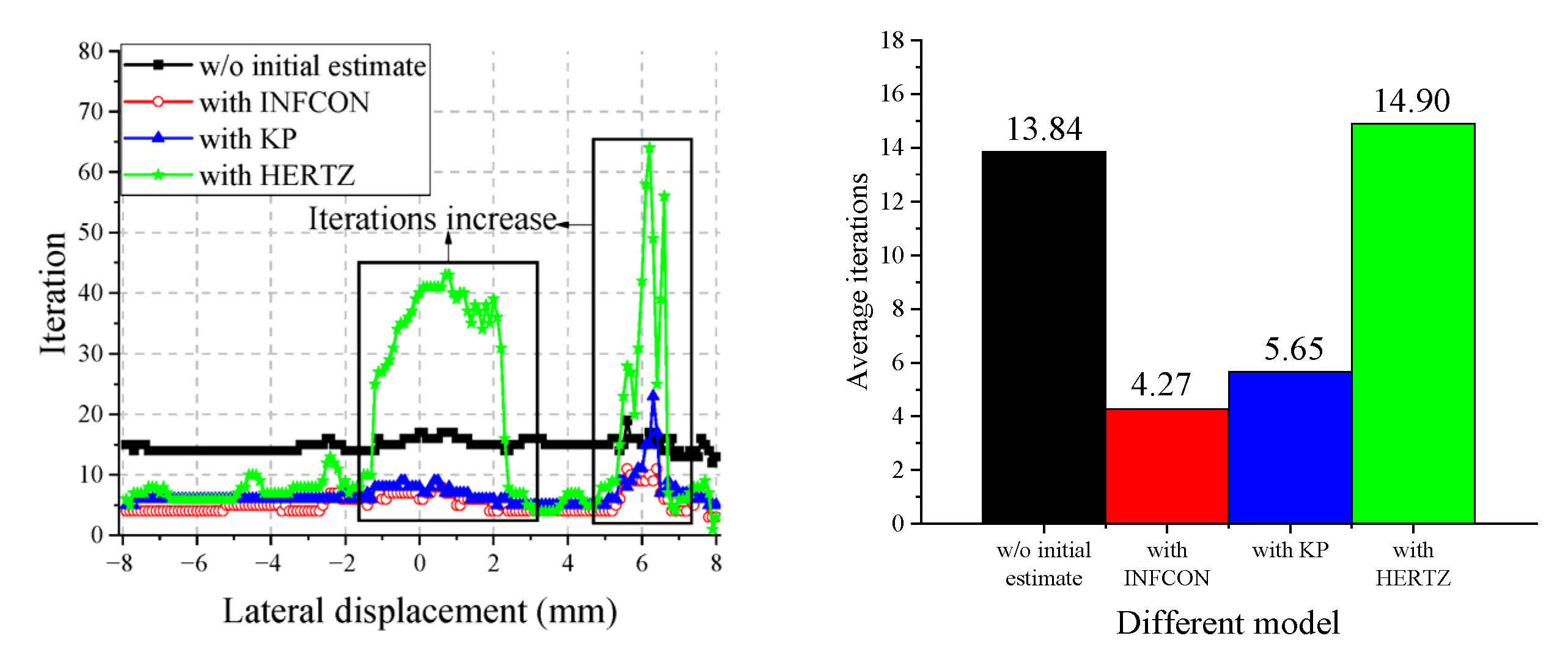
As demonstrated in Figure 7, the number of iterations varies in accordance with the lateral wheel set displacement, which is shown to range from −8 to 8 mm, with an increment of 0.1 mm. This choice result in the number of contact cases Nc = 1601. The mean iteration count for the Extended CG algorithm in the absence of an initial estimate is demonstrated as 13.84. By contrast, the iterations decrease to 4.27 and 5.65 when it uses an initial estimate of INFCON and KP, whereas the iteration increases to 14.90 for the solution with Hertz. As explained in Figure 4, the contact patch predicted by INFCON and KP are close to the exact solution, and then they help accelerate convergence of iteration. Hertz is erroneous in its prediction of the contact shape, particularly in instances where the contact shape manifests as highly non-elliptical, as illustrated in Figure 6.

4.1.3. The Influence of Normal Tolerance Error ε n on Computational Accuracy and Efficiency

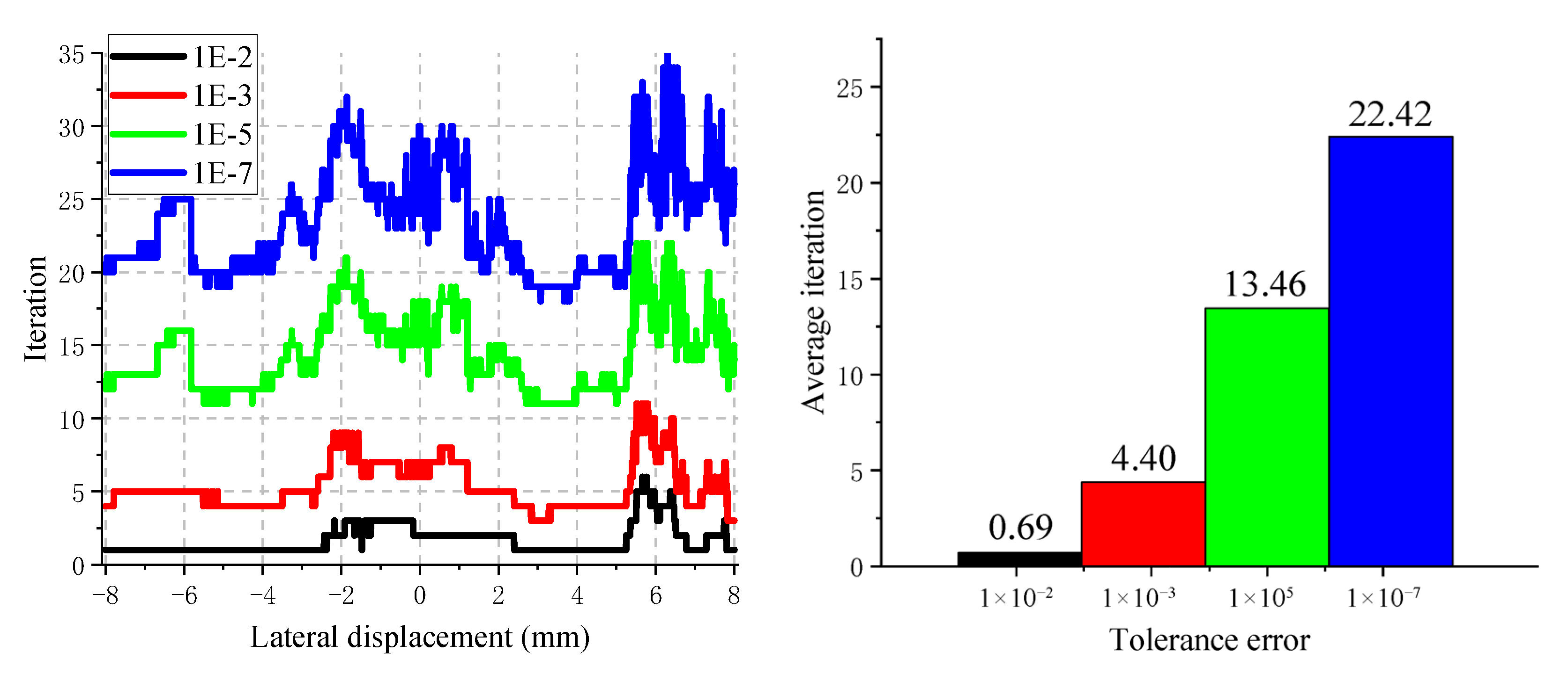
Figure 8 shows the comparison results of average iterations and computational cost when ε n is reduced from 1 × 10⁻² to 1 × 10⁻⁷, the lateral displacement is increased from −8 mm to 8 mm, and the increment is 0.01 mm, including 1601 cases. It can be seen from the results that, as the ε n decreases, the average iterations and computational cost increase exponentially. The reason is that, to achieve a smaller ε n , the BEM algorithm needs to go through more iterations, which increase the iterations and computational cost.
In addition, when the ε n is 1 × 10⁻², the average iteration is 0.69. The reason is that the calculation results of the simplified model INFCON in some cases meet the accuracy requirements and do not need to enter the BEM algorithm to iterate.
The influence of ε n from 1 × 10⁻² to 1 × 10⁻⁷ on the calculation accuracy is calculated in Figure 9, which compares the cumulative distribution function (CDF) of the normal contact force, the maximum contact pressure, and the contact patch calculation results. The reference is in Table 4. The figure contains 1601 contact cases in which the lateral displacement increases from −8 mm to 8 mm with a step size of 0.01 mm. The calculation results show that the accuracy of the calculation results is significantly improved with the decrease of ε n . The calculation results are obviously closer to the reference value.
The above results are summarized in Table 4. The results show that, with the decrease of ε n , the iterations will be significantly increased, and the calculation accuracy will also be significantly improved, while the calculation time will be significantly increased. Therefore, to ensure that the accuracy of the calculation results is 95% and the calculation error does not exceed 5%, a reasonable value is proposed. In this section, ε n is recommended to be 1 × 10⁻³, to ensure that the calculation accuracy is lost as little as possible, and to ensure that the iterations and the computational cost are not too great.

4.2. The Influence of Initial Estimate on Tangential Contact

4.2.1. Performance for Hertz Contact

The present study continues to focus on the influence of the Hertz tangential contact on this method. The normal contact condition is consistent with Section 4.1.1, and only the longitudinal creepage is considered to set 0.001. The longitudinal creepage and spin are set to zero. The application of the Coulomb friction law results in the determination of the friction coefficient f being set to 0.4. In this instance, the focus is on the impact of the initial estimate utilizing the FaStrip method.
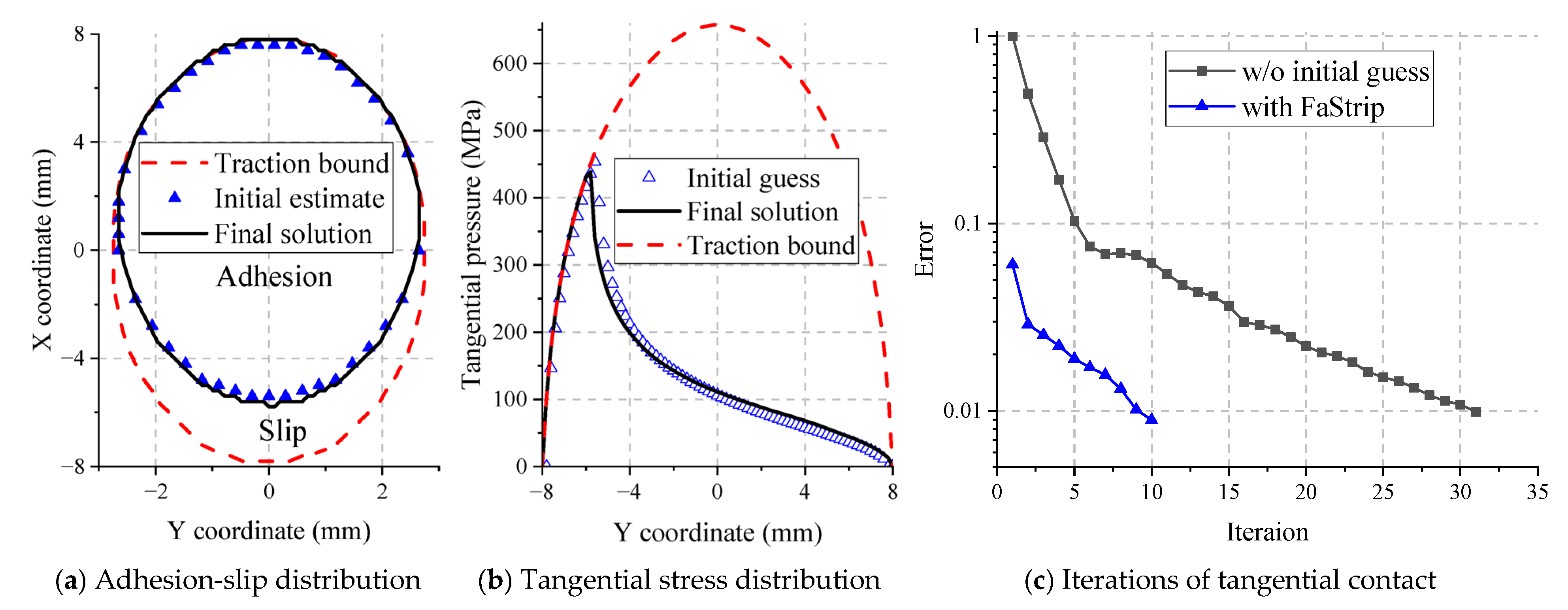
Figure 10 shows the influence of the initial estimate on tangential contact under Hertz contact, including tangential stress distribution and iterations. In this case, an error tolerance of 1 × 10⁻² is used. The specific reason is explained in Section 4.2.3. The solution from the ConvexGS algorithm without an initial estimate (w/o initial estimate) is used as a comparison. For adhesion-slip and pressure distribution, the initial estimated solution by FaStrip for adhesion-slip and pressure distribution exhibits a high degree of convergence with the final solution, with a discrepancy of only 0.06. It is evident that the iteration is considerably reduced from 31 to 10 in comparison with the solution that does not incorporate an initial estimate.
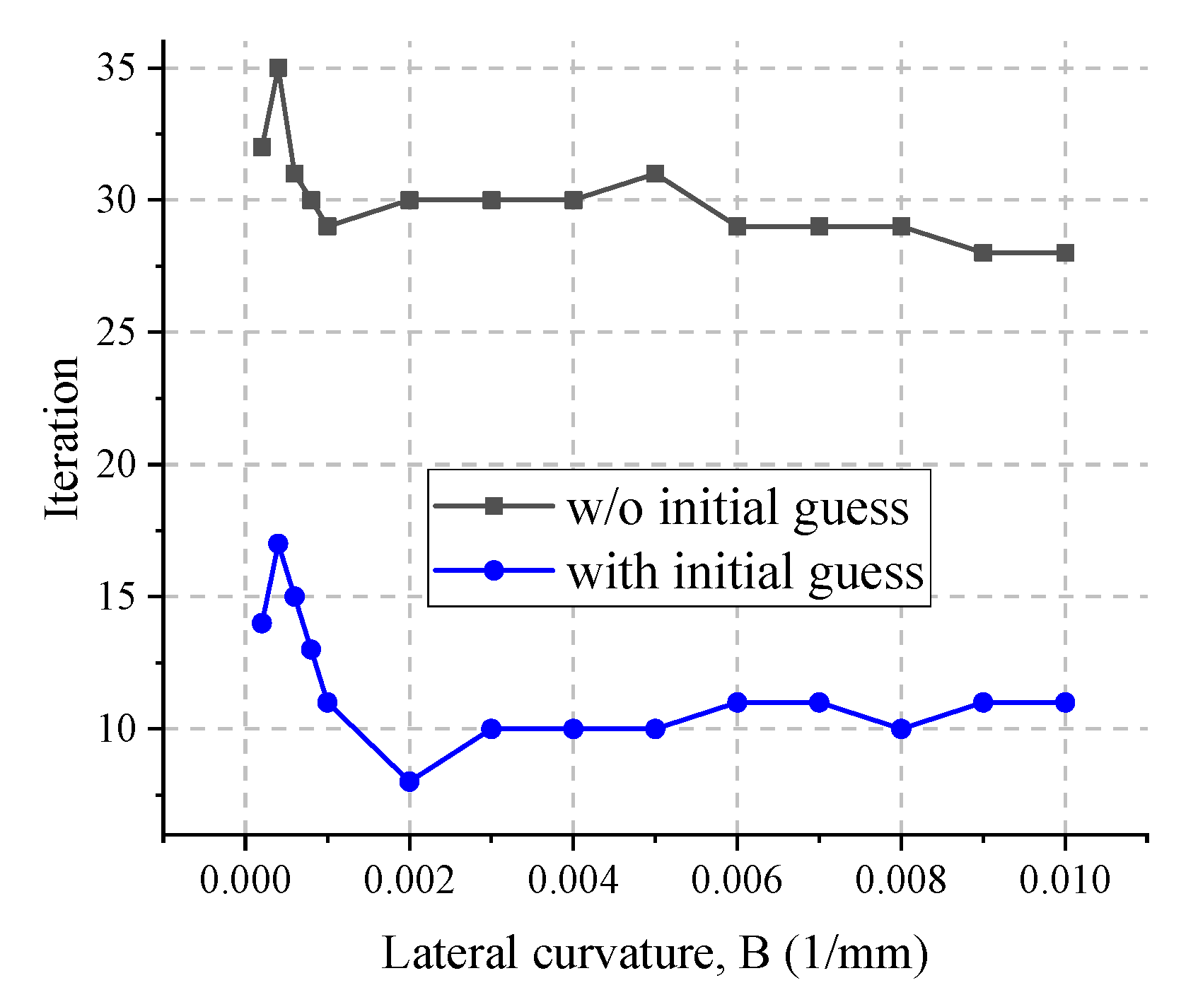
Further, Figure 11 compares more Hertz contact cases with A   =   0.001   m m 1 and increasing lateral curvature B from 2 × 10⁻⁴ to 1 × 10⁻² mm−1. In these cases, it can be seen that, for the solution without an initial estimate, the number of iterations is maintained at 24~33. In comparison, the number of iterations is maintained at 8~19 by using the FaStrip calculation with the initial estimate, which significantly reduces the number of iterations.

4.2.2. Performance for Non-Hertz Contact of Wheel and Rail

We further consider the non-Hertzian tangential contact between the wheel and rail. The normal contact condition of Section 4.1.2 is used, in which the friction coefficient is set to 0.4.
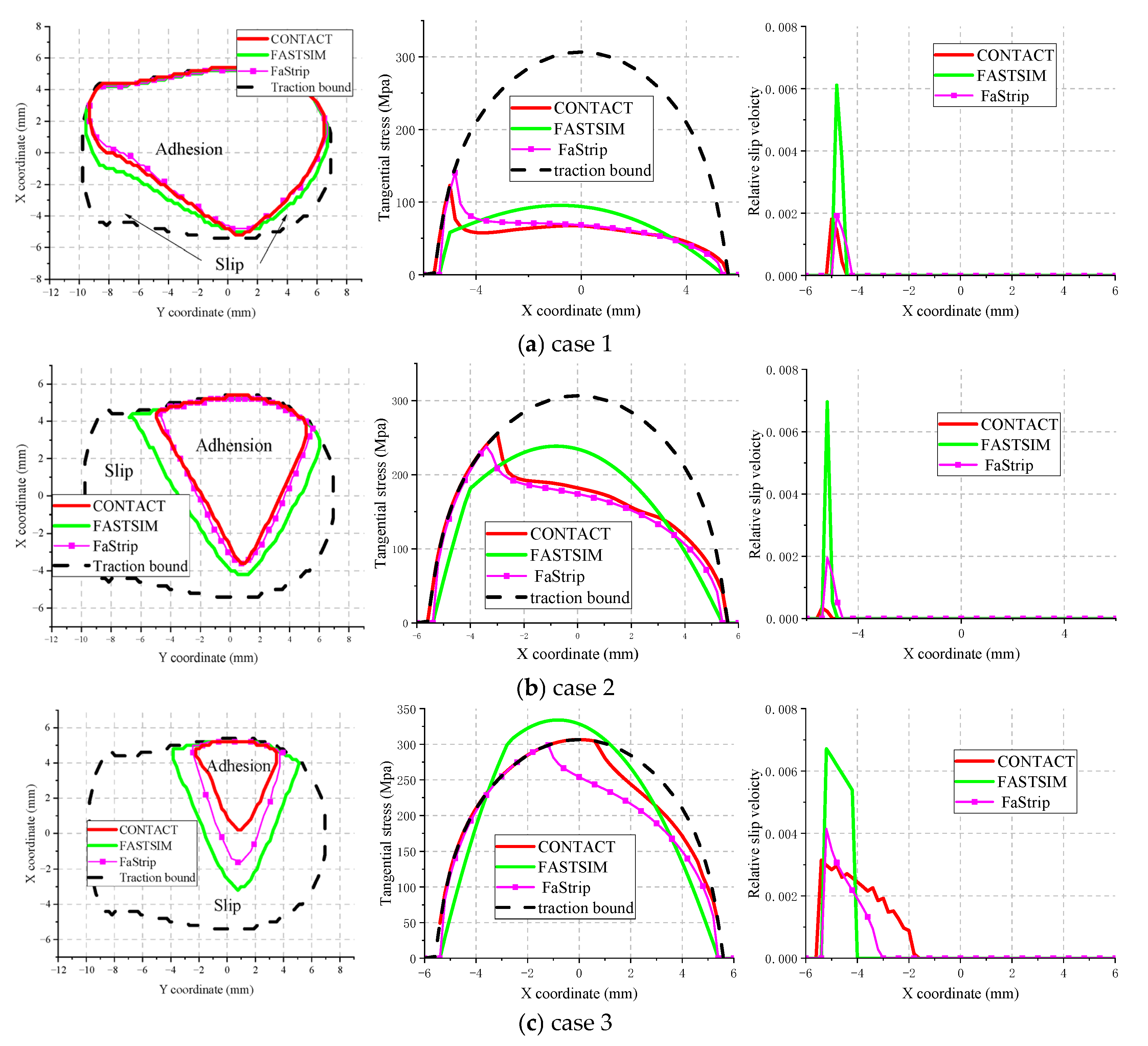
To provide an accurate reference, Figure 12 shows the results of tangential contact calculated by the CONTACT algorithm under three different creepage settings with lateral wheelset displacements of −2 mm. The creepage settings are shown in Table 5, ranging from small to large for cases 1 to 3. As can be seen in Figure 10, these three contact cases correspond to slight, moderate, and large creep.
Figure 13 compares adhesion-slip distribution, tangential stress, and relative slip velocity of longitudinal (y = 0 mm) for the above three cases. The results are predicted by two simplified contact models and exact solution CONTACT. The accuracy for the simplified contact models (FASTSIM, FaStrip) vary from low to high. The adhesion-slip distribution and tangential stress results calculated by FaStrip are more accurate than those calculated by FASTSIM; however, the relative slip velocity calculation has a large margin of error.
For the three cases, Figure 14 compares the iteration from the three contact models with or without an initial estimate. The convergence error is set as 1 × 10⁻². Figure 14 shows that, without an initial estimate, the iterations are 29, 29, and 16 in the three cases of nonlinear reduction in the logarithmic coordinate system. FASTSIM provides input values with large errors, which cannot reduce the iterations correctly; the iterations are 27, 23, and 12. The FaSrip algorithm is more accurate and computationally efficient, reducing the number of iterations to 13, 8, and 5.
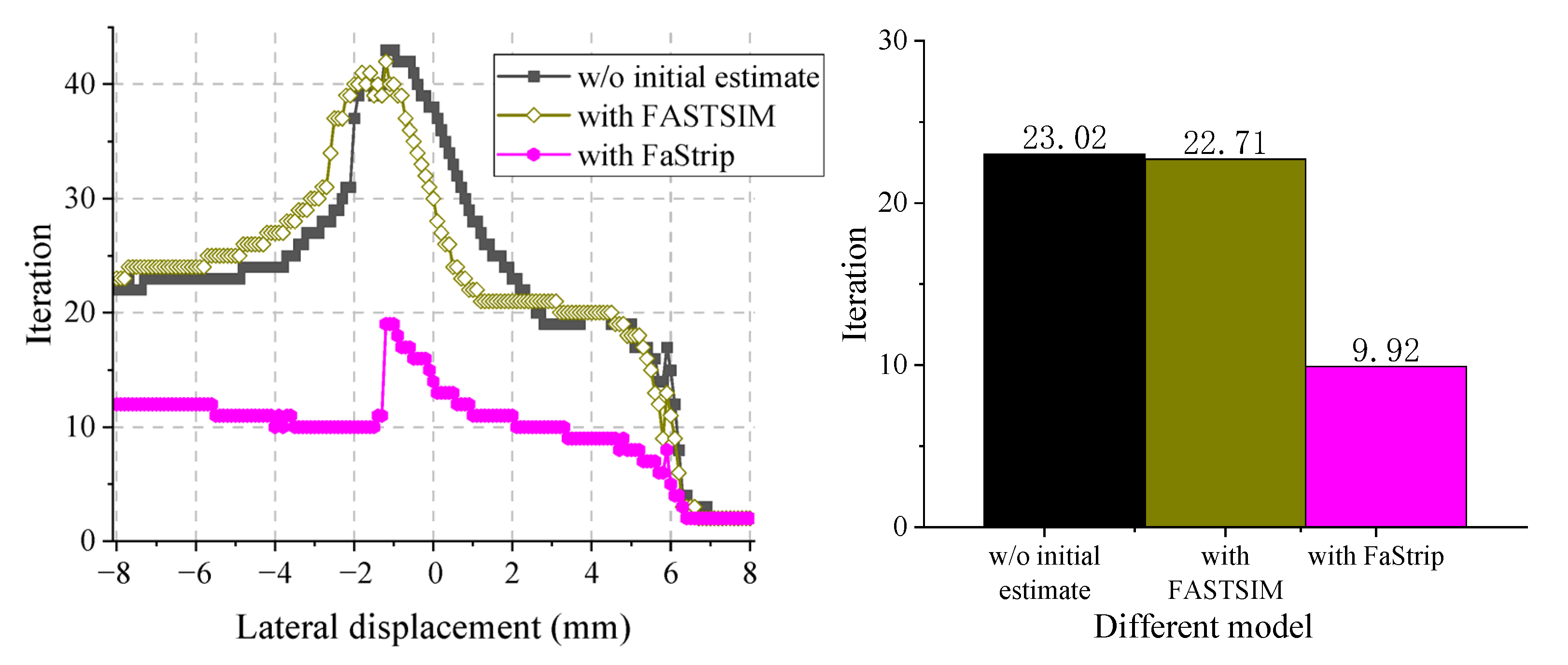
Further, we consider more non-Hertz cases, considering the actual wheel–rail contact conditions. Figure 15 shows the variation in iterations when the lateral wheelset displacement increases from −8 to 8 mm. It shows the average iteration is 23.02 for the ConvexGS algorithm without an initial estimate. By contrast, iterations decrease to 9.92 when an initial accurate FaStrip estimate is used, increasing computational efficiency by 56.9%. Using the FSATSIM algorithm with a poor initial prediction has no significant effect; iterations remain at 22.71.

4.2.3. The Influence of Tangential Tolerance Error ε τ on Computational Accuracy and Efficiency

Finally, we discuss the influence of tolerance error on the accuracy and computational efficiency of the BEM algorithm. The reason is that the selection of tolerance error is very important. Too large a tolerance error will lead to a huge calculation error, while too small a tolerance error will significantly reduce computational efficiency.
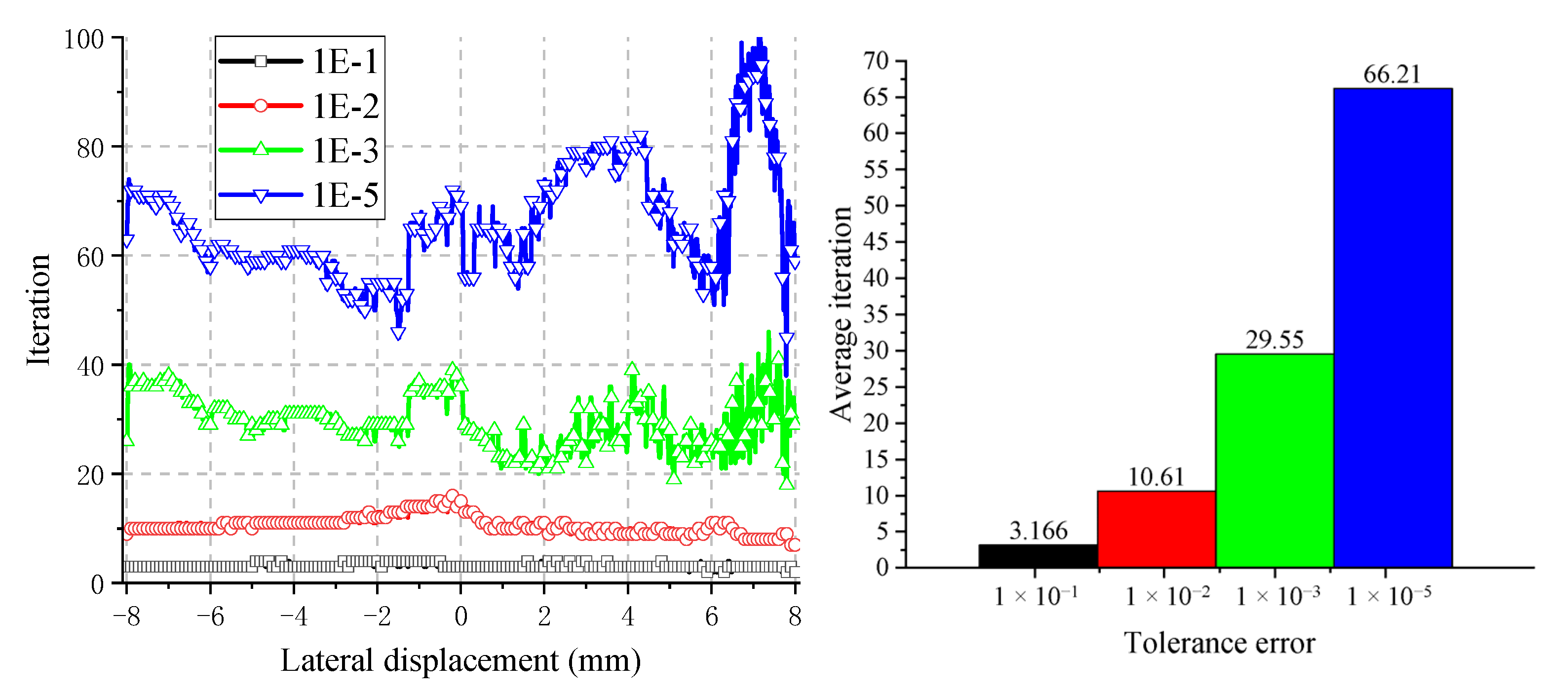
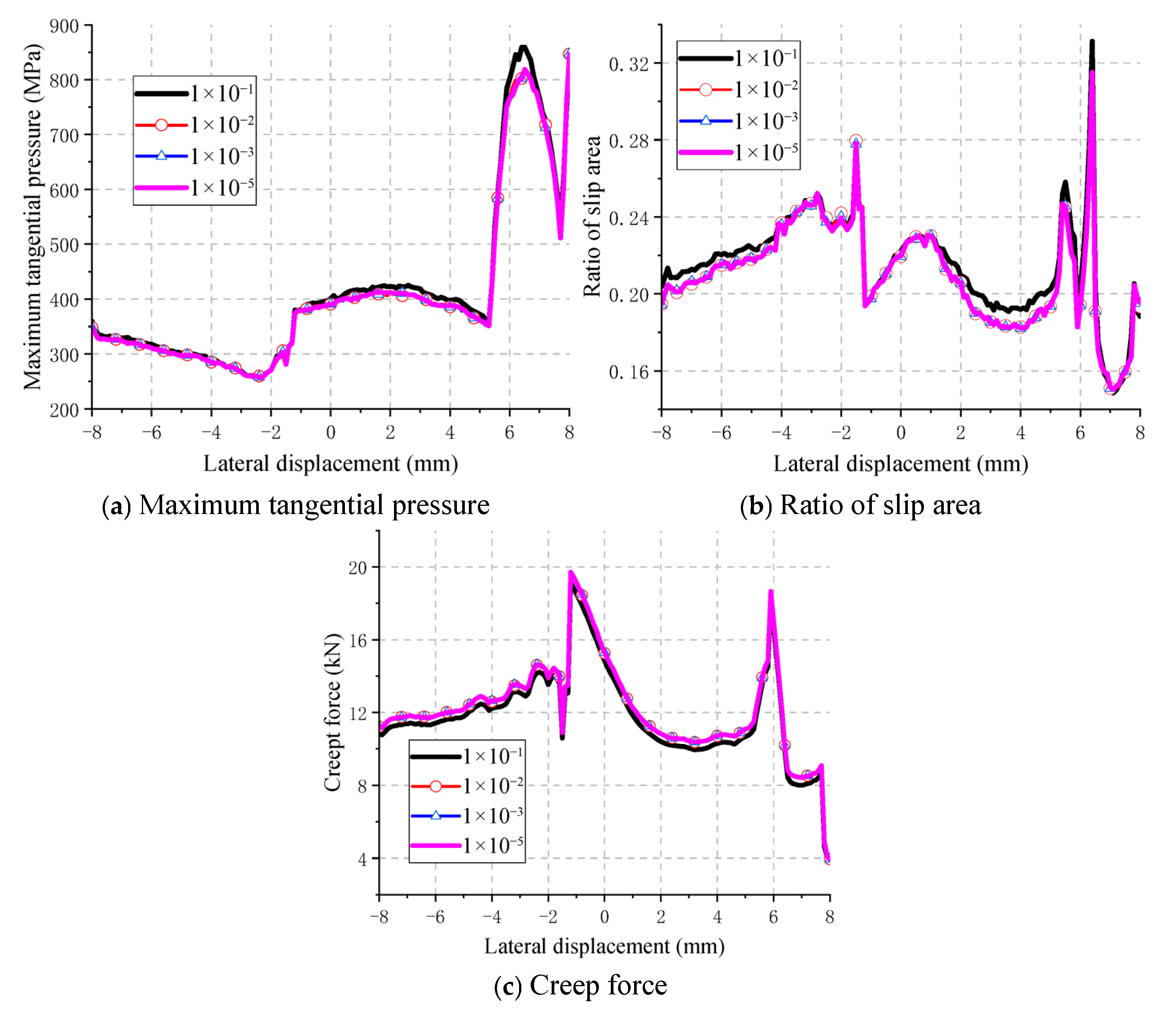
Figure 16 shows the comparison results of average iterations and computational cost when ε τ is reduced from 1 × 10⁻¹ to 1 × 10⁻⁵, the lateral displacement is increased from −8 mm to 8 mm, and the increment is 0.1 mm, including 161 cases. It can be seen that, as the ε τ decreases from 1 × 10⁻¹ to 1 × 10⁻⁵, the average iterations increase exponentially from 3.17 to 66.21. The reason is that, to achieve a smaller ε τ , the BEM algorithm needs to go through more iterations, which increase the iterations and computational cost.
The influence of ε τ increasing from 1 × 10⁻² to 1 × 10⁻⁷ on the calculation accuracy is calculated in Figure 17, which compares the maximum tangential pressure, ratio of slip area to contact area, and total creep force under different lateral displacement conditions. The calculation results show that the accuracy of the calculation results is significantly improved with the decrease in ε τ . The calculation results are obviously closer to the reference value. When ε τ is 1 × 10⁻¹, the results still have a certain error, but, when ε τ is less than 1 × 10⁻², the calculation results are basically consistent.
The above results are summarized in Table 6. The results show that, with the decrease in ε τ , the iterations will be significantly increased, and the calculation accuracy will also be significantly improved. However, when ε τ is less than 1 × 10⁻², the relative error is less than 1%. Continuing to reduce ε τ will great increase iterations, sacrificing too much computational efficiency. Thus, ε τ is recommended to be 1 × 10⁻², that is, to ensure that the calculation accuracy is lost as little as possible, and to ensure that the iterations and the computational cost are not too large.

5. Conclusions and Outlook

In this paper, a new initial estimate method is proposed to accelerate the calculation speed of the wheel–rail contact boundary element modeling of rolling contact. The program is written to verify the feasibility of the initial estimate method under both Hertz and non-Hertz typical cases. The calculation efficiency and accuracy are then compared with the BEM without an initial estimate. This is performed in order to analyze the influence of the initial solution estimate method on efficient boundary element modeling. The following conclusions are obtained:
In a normal contact part, the initial estimate method can significantly reduce the iterations and improve the calculation efficiency by 70%~90% in the Hertz case. The calculation efficiency in non-Hertz cases is enhanced by the simplified algorithm. Utilizing the more accurate INFCON algorithm results in an increase of approximately 60–70% in computational efficiency. By comparing the initial estimate results of the INFCON, KP, and Hertz simplified models, it is found that the initial prediction of the contact patch shape is the most important for reducing iterations, followed by the contact normal pressure.
In the tangential contact part, the initial estimate method can significantly reduce the iterations and improve the calculation efficiency by 50%~80% in the Hertz case. The calculation efficiency in non-Hertz cases is enhanced by the simplified algorithm. Utilizing the more accurate FaStrip algorithm results in an increase of approximately 60–70% in computational efficiency.
The initial estimate method proposed in this paper also has limitations. Firstly, it is important to note that the initial estimate models utilized in this method are predicated on certain assumptions. Firstly, it is assumed that the contact area satisfies the elastic half-space assumption [40], and secondly, the simplified model calculation simplifies the contact patch shape along the longitudinal symmetry distribution [41]. Therefore, when the method is used to calculate the contact calculation, the asymmetric contact calculation along the longitudinal direction, such as the yaw angle and the geometric irregularity, is included [42,43]. Secondly, the computational effectiveness of this method and the control parameters and recommended values discussed in Section 4 are all for wheel–rail contact. Further research is required to ascertain whether the effect is significant when calculating contact based on other BEMs [44,45].

Author Contributions

S.C.: Conceptualization, Investigation, and Software; H.L.: Conceptualization, Methodology and Writing—Original Draft; B.A.: Methodology, Investigation, Project Administration, and Editing; J.L.: Supervision, Investigation, and Resources. All authors have read and agreed to the published version of the manuscript.

Funding

This research was funded by [China State Railway Group Corporation Limited] grant number [N2023G063] and [National Natural Science Foundation of China] grant number [52478468].

Data Availability Statement

The data presented in this study are available on request from the corresponding author. The data are not publicly available due to restrictions on privacy.

Conflicts of Interest

Author Jiapeng Liu was employed by the company China Academy of Railway Sciences Corporation Limited. The remaining authors declare that the research was conducted in the absence of any commercial or financial relationships that could be construed as a potential conflict of interest.

References

  1. An, B. Numerical Study of Wheel-Rail Rolling Contact Behavior. Ph.D. Thesis, Southwest Jiaotong University, Sichuan, China, 2020. [Google Scholar]
  2. Yan, W.; Fischer, F.D. Applicability of the Hertz contact theory to rail-wheel contact problems. Arch. Appl. Mech. 2000, 70, 255–268. [Google Scholar] [CrossRef]
  3. Deng, X.; Qian, Z.; Li, Z.; Dollevoet, R. Applicability of half-space-based methods to non-conforming elastic normal contact problems. Int. J. Mech. Sci. 2017, 126, 229–234. [Google Scholar] [CrossRef]
  4. Deng, X.; Qian, Z.; Li, Z. Numerical modeling of dynamic frictional rolling contact with an explicit finite element method. Tribol. Int. 2019, 129, 214–231. [Google Scholar] [CrossRef]
  5. Pun, C.L.; Kan, Q.; Mutton, P.J.; Kang, G.; Yan, W. An efficient computational approach to evaluate the ratcheting performance of rail steels under cyclic rolling contact in service. Int. J. Mech. Sci. 2015, 101, 214–226. [Google Scholar] [CrossRef]
  6. Kalker, J.J. Rolling contact phenomena—Linear elasticity. In Rolling Contact Phenomena, CISM Courses and Lectures; Jacobson, B., Kalker, J., Eds.; Springer: New York, NY, USA, 2000; pp. 1–84. [Google Scholar]
  7. Knothe, K. A contribution to the calculation of the contact stress distribution between two elastic bodies of revolution with non-elliptical contact area. Comput. Struct. 1984, 18, 1025–1033. [Google Scholar] [CrossRef]
  8. Yu, C.; Yaoliang, S.; Wenhao, D.; Ping, W. Assessing the fast non-Hertzian methods for wheel-rail rolling contact integrated in the vehicle dynamics simulation. Proc. Inst. Mech. Eng. Part F J. Rail Rapid Transit. 2023, 237, 371–384. [Google Scholar] [CrossRef]
  9. Triantafyllidis, T. 3-D time domain be using half-space green-functions. Eng. Anal. Bound. Elem. 1991, 8, 115–124. [Google Scholar] [CrossRef]
  10. Chen, Y.; Yu, Z.; Wang, H.; Fan, Y.; An, B.; Chen, P.; Wang, P. Study on the Influence of Wheel-rail Conformal Contact Modeling on Vehicle-track Coupling Dynamics. Railw. Stand. Des. 2025, 69, 12–23. [Google Scholar] [CrossRef]
  11. Huang, S.; Zhao, X.; Cai, Y.; Wem, Z. Modeling of Wheel-Rail Adhesion Behavior at Large Creepages Based on Polach Adhesion Theory. J. Tribol. 2025, 69, 133–155, (In Chinese and English). [Google Scholar]
  12. Yang, Z.; Boogaard, A.; Chen, R.; Dollevoet, R.; Li, Z. Numerical and experimental study of wheel-rail impact vibration and noise generated at an insulated rail joint. Int. J. Impact Eng. 2018, 113, 29–39. [Google Scholar] [CrossRef]
  13. Yang, Z.; Boogaard, A.; Wei, Z.; Liu, J.; Dollevoet, R.; Li, Z. Numerical study of wheel-rail impact contact solutions at an insulated rail joint. Int. J. Mech. Sci. 2018, 138, 310–322. [Google Scholar] [CrossRef]
  14. Zhao, X.; An, B.; Zhao, X.; Wen, Z.; Jin, X. Local rolling contact fatigue and indentations on high-speed railway wheels: Observations and numerical simulations. Int. J. Fatigue 2017, 103, 5–16. [Google Scholar] [CrossRef]
  15. Zhao, X.; Huang, S.; Yang, J.; Yang, Z.; Wen, Z. On Transient Wheel-Rail Rolling-Sliding-Jumping Contact and Critical Sizes of Short/Medium-wave Irregularities at Higher Speeds. Railw. J. 2024, 46, 21–32. [Google Scholar]
  16. Zhao, X.; Wen, Z.; Wang, H.; Jin, X.; Zhu, M. Modeling of high-speed wheel-rail rolling contact on a corrugated rail and corrugation development. J. Zhejiang Univ. Sci. A 2014, 15, 946–963. [Google Scholar] [CrossRef]
  17. An, B.; Wang, P. A novel local ellipse method for ellipse-based tangential contact model applied to wheel-rail contact. Int. J. Rail Transport. 2022, 12, 180–199. [Google Scholar] [CrossRef]
  18. Kalker, J.J. The computation of three-dimensional rolling contact with dry friction. Int. J. Numer. Methods Eng. 1979, 14, 1293–1307. [Google Scholar] [CrossRef]
  19. Kalker, J.J. Three-Dimensional Elastic Bodies in Rolling Contact; Kluwer Academis Publishers: Dordrecht, The Netherlands, 1990. [Google Scholar]
  20. Vollebregt, E.A.H. A new solver for the elastic normal contact problem using conjugate gradients: Deflation, and an FFT-based preconditioner. J. Comput. Phys. 2014, 257, 333–351. [Google Scholar] [CrossRef]
  21. Zhao, J.; Vollebregt, E.A.H.; Oosterlee, C.W. A fast nonlinear conjugate gradient based method for 3D concentrated frictional contact problems. J. Comput. Phys. 2015, 288, 86–100. [Google Scholar] [CrossRef]
  22. Vollebregt, E.A.H. 100-fold speedup of the normal contact problem and other developments in CONTACT. In Proceedings of the CM 2012, Chengdu, China, 15 March 2012; Southwest Jiaotaong University: Chengdu, China, 2012; pp. 79–86. [Google Scholar]
  23. Polonsky, I.A.; Keer, L.M. A numerical method for solving rough contact problems based on the multi-level multi-summation and conjugate gradient techniques. Wear 1999, 231, 206–219. [Google Scholar] [CrossRef]
  24. Piotrowski, J.; Kik, W. A simplified model of wheel/rail contact mechanics for non-Hertzian problems and its application in rail vehicle dynamic simulations. Veh. Syst. Dyn. 2008, 46, 27–48. [Google Scholar] [CrossRef]
  25. Piotrowski, J.; Chollet, H. Wheel–rail contact models for vehicle system dynamics including multi-point contact. Veh. Syst. Dyn. 2005, 43, 455–483. [Google Scholar] [CrossRef]
  26. Ayasse, J.B.; Chollet, H. Determination of the wheel rail contact patch in semi-Hertzian conditions. Veh. Syst. Dyn. 2005, 43, 161–172. [Google Scholar] [CrossRef]
  27. Liu, B.; Bruni, S.; Vollebregt, E. A non-Hertzian method for solving wheel–rail normal contact problem taking into account the effect of yaw. Veh. Syst. Dyn. 2016, 54, 1226–1246. [Google Scholar] [CrossRef]
  28. Sun, Y.; Zhai, W.; Guo, Y. A robust non-Hertzian contact method for wheel–rail normal contact analysis. Veh. Syst. Dyn. 2018, 56, 1899–1921. [Google Scholar] [CrossRef]
  29. Zhu, B.; Zeng, J.; Wang, Q.; Wu, Y.; Qu, S. Modification of the semi-Hertz wheel–rail contact method based on recalculating the virtual penetration value. Veh. Syst. Dyn. 2018, 57, 1407–1420. [Google Scholar] [CrossRef]
  30. Kalker, J.J. A fast algorithm for the simplified theory of rolling contact. Veh. Syst. Dyn. 1982, 11, 1–13. [Google Scholar] [CrossRef]
  31. Vollebregt, E.A.H.; Wilders, P. FASTSIMsd a second-order accurate frictional rolling contact algorithm. Comput. Mech. 2011, 47, 105–116. [Google Scholar] [CrossRef]
  32. Sichani, M.S.; Enblom, R.; Berg, M. An alternative to FASTSIM for tangential solution of the wheel–rail contact. Veh. Syst. Dyn. 2016, 54, 748–764. [Google Scholar] [CrossRef]
  33. Kik, W.; Piotrowski, J. A fast, approximate method to calculate normal load at contact between wheel and rail and creep forces during rolling. In Proceedings of the Second Mini Conference on Contact Mechanics and Wear of Rail/Wheel Systems, TU Budapest, Budapest, Hungary, 29–31 July 1996. [Google Scholar]
  34. Wang, K. Calculation of wheel contact point trace and wheel/rail contact geometric parameters. J. Southwest Jiaotong Univ. 1984, 18, 89–99. [Google Scholar]
  35. Liu, S.; Wang, Q.; Liu, G. A versatile method of discrete convolution and FFT (DC-FFT) for contact analyses. Wear 2000, 243, 101–111. [Google Scholar] [CrossRef]
  36. Hertz, H. Über die Berührung fester elastischer Körper. J. Reine Und Angew. Math. 1882, 92, 156–171. [Google Scholar] [CrossRef]
  37. An, B.; Wang, P. A wheel-rail normal contact model using the combination of virtual penetration method and strip-like Boussinesq’s integral. Veh. Syst. Dyn. 2022, 61, 1583–1601. [Google Scholar] [CrossRef]
  38. Vollebregt, E.A.H. Improving the speed and accuracy of the frictional rolling contact model ‘CONTACT’. In Proceedings of the 10th International Conference on Computational Structures Technology, Valencia, Spain, 14–17 September 2010; Topping, B.H.V., Ed.; [Google Scholar]
  39. Vollebregt, E.A.H. A Gauss-Seidel type solver for special convex programs, with application to frictional contact mechanics. J. Optim. Theory Appl. 1995, 87, 47–67. [Google Scholar] [CrossRef]
  40. Goryacheva, I.G.; Tsukanov, I.Y. Modeling of normal contact of elastic bodies with surface relief taken into account. J. Phys. Conf. Ser. 2018, 991, 012028. [Google Scholar] [CrossRef]
  41. Huang, J.; Wu, B.; Li, D.; Wang, Z. Comparison of Results from Different Wheel-Rail Rolling Contact Models Considering Large Creepages. J. Railw. 2025, 47, 57–65. [Google Scholar]
  42. Alonso, A.; Giménez, J.G. A new method for the solution of the normal contact problem in the dynamic simulation of railway vehicles. Veh. Syst. Dyn. 2005, 43, 149–160. [Google Scholar] [CrossRef]
  43. Skipper, W.; Meierhofer, A.; Chalisey, A.; Six, K.; Lewis, R. Generation of Sanded Creep Curves Using the Extended Creep Force Model with High Pressure Torsion Data. Wear 2024, 542, 205278. [Google Scholar] [CrossRef]
  44. Majumdar, A.; Tien, C.L. Fractal Characterization and Simulation of Rough Surfaces. Wear 1990, 136, 313–327. [Google Scholar] [CrossRef]
  45. Zhou, S.; He, C.; Di, H. An efficient method for predicting train-induced vibrations from a tunnel in a poroelastic half-space. Eng. Anal. Bound. Elem. 2017, 85, 43–56. [Google Scholar] [CrossRef]
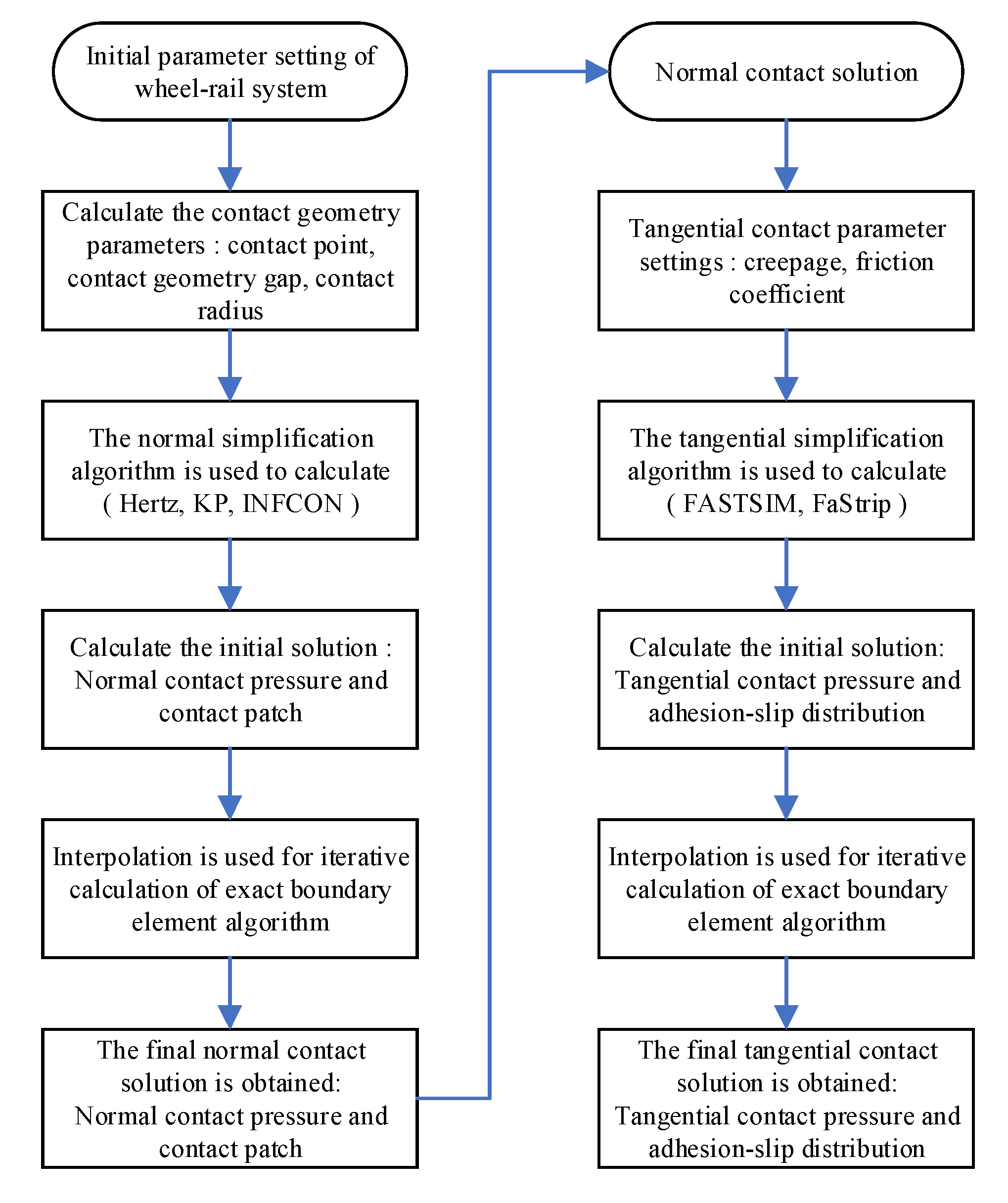
Figure 1. Schematic of initial estimate method on efficient boundary element modeling.
Lubricants 13 00508 g001
Figure 2. Comparison of contact patch, normal pressure, and iteration error by two models.
Lubricants 13 00508 g002
Figure 3. The influence of initial estimate on normal contact iteration with lateral curvature B.
Lubricants 13 00508 g003
Figure 4. Contact patch and normal pressure (y = 0) for three shifts with different models.
Lubricants 13 00508 g004
Figure 5. The influence of different initial estimate normal models on iteration.
Lubricants 13 00508 g005
Figure 6. Contact patch and pressure distribution under different lateral displacements.
Lubricants 13 00508 g006
Figure 7. The influence of different models’ initial estimates on normal iteration with lateral displacement.
Lubricants 13 00508 g007
Figure 8. The influence of normal tolerance error on iteration and computational cost.
Lubricants 13 00508 g008
Figure 9. The influence of normal tolerance error on accuracy.
Lubricants 13 00508 g009
Figure 10. Comparison of A/S distribution tangential stress and iteration error by two models.
Lubricants 13 00508 g010
Figure 11. The influence of initial estimate on tangential contact iteration with lateral curvature B.
Lubricants 13 00508 g011
Figure 12. Tangential contact results for three cases.
Lubricants 13 00508 g012
Figure 13. A-S distribution, tangential stress, and relative slip velocity of longitudinal for three shifts with different models.
Lubricants 13 00508 g013
Figure 14. The influence of different initial estimate tangential models on iteration.
Lubricants 13 00508 g014
Figure 15. The influence of different model initial estimates on tangential iteration with lateral displacement.
Lubricants 13 00508 g015
Figure 16. The influence of tangential tolerance error on iteration.
Lubricants 13 00508 g016
Figure 17. The influence of tangential tolerance error on accuracy.
Lubricants 13 00508 g017
Table 1. Comparison of different contact methods.
MethodCharacteristicAdvantageDisadvantage
The accurate solutionFinite Element MethodBy dividing the wheel–rail system into physical units, contact is simulated using the penalty function method.Simulation of real wheel–rail contact geometry and material nonlinearity.Low computational efficiency. The finer the grid, the exponential higher growth of computing time.
Boundary Element MethodOnly the contact surface is divided into grids.High calculation precision.The process requires iterative refinement until convergence is achieved, and its computational efficiency is suboptimal.
The simplified solutionVirtual Penetration MethodAssuming the wheel/rail profiles can rigidly penetrate each other, the elastic deformation of the material can be equivalent to the reduction factor.It has high computational efficiency, no iteration, and analytical solution.The calculation’s precision is suboptimal, and significant calculation errors are observed when the transverse displacement and gauge angle are both large.
Table 2. Comparison of simplified normal contact models.
MethodCharacteristicEfficiencyPrecision
HertzBased on the ellipse hypothesis, the contact patch and the contact pressure are elliptically distributed.HighestLow
KPBased on the virtual penetration method, the calculation result is non-Hertz.HighRather high
INFCONBased on virtual penetration method and Boussinesq integral.Rather highHighest
Table 3. Comparison of simplified tangential contact models.
MethodCharacteristicEfficiencyPrecision
FASTSIMBased on Kalker’s simplified theory development, based on the ellipse hypothesis, several strips along the rolling direction are formed, and each strip is divided into several rectangular elements.HighestLow
FaStripBased on the ellipse hypothesis, several strips along the rolling direction are formed, but the rectangular grid is not further divided.HighHigh
Table 4. The influence of normal tolerance error ε n .
ε n Average IterationsRelative Error (%)
Max. PressureContact AreaContact Force
1 × 10−20.691.563.730.63
1 × 10−34.400.402.050.10
1 × 10−513.460.341.580.04
1 × 10−722.420.140.600.01
Table 5. The setting of creepage of three cases.
CreepageLateralLongitudinalSpin
Case10.5 × 10−40.5 × 10−40.5 × 10−4
Case22 × 10−42 × 10−42 × 10−4
Case35 × 10−45 × 10−45 × 10−4
Table 6. The influence of tangential tolerance error ε τ .
ε n Average IterationsRelative Error(%)
Max. PressureContact AreaContact Force
1 × 10−13.171.231.673.38
1 × 10−210.610.140.277.87 × 10−2
1 × 10−329.555.9 × 10−27.98 × 10−26.51 × 10−3
1 × 10−566.215.58 × 10−43.34 × 10−41.26 × 10−4
Disclaimer/Publisher’s Note: The statements, opinions and data contained in all publications are solely those of the individual author(s) and contributor(s) and not of MDPI and/or the editor(s). MDPI and/or the editor(s) disclaim responsibility for any injury to people or property resulting from any ideas, methods, instructions or products referred to in the content.