Article

Effect of Substrate Bias on the Structure and Tribological Performance of (AlTiVCrNb)CxNy Coatings Deposited via Graphite Co-Sputtering

1
School of Mechatronics Engineering, Henan University of Science and Technology, Luoyang 471003, China
2
Collaborative Innovation Center of Henan Province for High-End Bearing, Henan University of Science and Technology, Luoyang 471000, China
3
Luoyang Bearing Group Co., Ltd., Luoyang 471000, China
4
Henan Key Laboratory for Machinery Design and Transmission System, Henan University of Science and Technology, Luoyang 471003, China
*
Author to whom correspondence should be addressed.
Lubricants 2024, 12(9), 325; https://doi.org/10.3390/lubricants12090325
Submission received: 6 August 2024 / Revised: 3 September 2024 / Accepted: 4 September 2024 / Published: 23 September 2024

Abstract

:
In the existing literature, there are few studies on the effect of deposition bias on the tribological properties of carbon-doped high-entropy alloy coatings. In order to further study the effect of the deposition bias on the properties of coatings, (AlTiVCrNb)CxNy coatings were deposited via unbalanced RF magnetron sputtering. The microstructure and tribological properties of carbon-doped high-entropy alloy ceramic coatings under different deposition biases were studied. The composition, morphology, crystal structure, and chemical morphology of each element of the coating were analyzed using scanning electron microscopy (SEM), X-ray diffraction (XRD), and X-ray photoelectron spectroscopy (XPS). The hardness, elastic modulus, friction, and wear properties of the coating were further characterized using a nanoindentation instrument, reciprocating sliding friction, a wear tester, and a white light interferometer. The coating density reached the optimal level when the deposition bias value was 90 V. The hardness and elastic modulus of the (AlTiVCrNb)CxNy coating increased first and then decreased with an increase in deposition bias, and the maximum hardness was 23.98 GPa. When the deposition bias was 90 V, the coating formed a good-quality carbon transfer film on the surface of the counterbody due to sp2 clusters during the friction and wear process. The average friction coefficient and wear rate of the (AlTiVCrNb)CxNy coating were the lowest, 0.185 and 1.6 × 10⁻⁷ mm3/N·m, respectively. The microstructure, mechanical properties, and tribological performance of the (AlTiVCrNb)CxNy coating were greatly affected by the change in deposition bias, and an (AlTiVCrNb)CxNy coating with excellent structure and friction properties could be prepared using graphite co-sputtering.

1. Introduction

With the rapid development of the aerospace industry, rolling bearings, as an important rotating component in aerospace equipment, are facing more complex working conditions, and their performance requirements are increasing. Solving the failure problem caused by friction and wear during their service process is imperative. A coating with good mechanical properties, a low friction coefficient, and a low wear rate can be prepared using modern surface modification technologies on the bearing contact surface, which is an effective way to ensure the normal operation of rolling bearings under complex working conditions, such as high speed and high load-carrying capacity [1,2,3]. A sulfide-based coating has been widely used in the aerospace industry. However, because of its poor hardness and wear resistance, it cannot operate under long-life and high-load conditions. It has the disadvantage of easily combining with oxygen atoms in the air and oxidizing in an atmospheric environment, so the application of the sulfide-based coating is limited [4,5,6].
Since Yeh et al. proposed the concept of a high-entropy alloy (HEA) in 2004, this new material with high entropy, lattice distortion, slow diffusion, and a cocktail effect has attracted wide attention, which has made the high-entropy alloy coating a research hotspot [7,8,9]. Magnetron sputtering is an effective means of preparing high-entropy alloy coatings. Scholars have carried out related studies, but work has mostly been confined to studying hard, high-entropy alloy coatings in micron and nanodevices, and the tribological performance of the coatings is poor [10,11,12]. It is important to prepare a high-entropy alloy coating with excellent tribological performance and expand the application scope of high-entropy alloy coating. Liu et al. [13] studied the influence of carbon content on the friction, wear, and corrosion resistance of laser-cladding CoCrFeMnNiCx high-entropy alloy coating. They confirmed that the addition of appropriate carbon can effectively improve the compressive strength and ductility of the material. Xin et al. [14] studied an Al0.2Co1.5CrFeNi1.5Ti0.5 coating and found that the coating wear rate was significantly improved by using a doping carbon element. Che et al. [15] studied the effect of carbon alloying on AlCrFeCoNi coating and found that the friction coefficient of the coating decreased by 51.89% after introducing the carbon element. The above studies show that, as a special non-metallic element, carbon doped in a high-entropy alloy coating can improve the structure and tribological performance of the coating. Zhuang et al. [16] introduced TiC (4 wt%) into the CrMnFeCoNi coating and compared it with the coating without TiC, showing that the friction coefficient of the coating decreased by 51.89%. The abovementioned studies demonstrate that the high-entropy alloy carbide coating exhibits excellent wear resistance, and the introduction of carbon in the coating reduces the wear rate.
In this study, in order to improve the tribological performance of high-entropy alloy nitride coating, a carbon element is introduced into the high-entropy alloy nitride coating. (AlTiVCrNb)CxNy coatings were prepared using unbalanced magnetron sputtering, and the effects of the deposition bias (Zc) on the composition, structure, and tribological performance of (AlTiVCrNb)CxNy coatings were studied.

2. Experiments and Methods

In the experiment, the coating was prepared using a magnetron sputtering deposition system produced by the Shenyang Keyi Factory of the Chinese Academy of Sciences, Shenyang, China. The microstructure, mechanical properties, and frictional performance of the coating were tested on 9Cr18 steel and Si sheet. Before the test, the substrate was first polished and then ultrasonically cleaned with acetone and ethanol. The target material was installed in the vacuum chamber, and AlTiVCrNb high-entropy alloy blocks with equal molar ratios were prepared using the powder metallurgy process. In addition, a Cr target and a graphite target were used in the chamber as the deposition transition layer and doped C element, respectively. The target size was φ50 mm × 3 mm; the graphite target was prepared using the same method. Its composition is shown in Table 1. Before deposition, the Cr transition layer was deposited on the substrate for 10 min to enhance the bonding strength of the coating film base. During the deposition process, high-purity argon and nitrogen (purity of 99.99%) were used as the sputtering and reaction gas, respectively. The AlTiVCrNb target and graphite target were sputtered at the same time. The sample rack was rotated at a speed of 20 r/min, and the samples were prepared using two sputtering targets in turn. The main process parameters were as follows: the vacuum degree in the vacuum chamber was 5.0 × 10⁻⁴ Pa, the nitrogen flow rate was 20 mL/min, the argon flow rate was 20 mL/min, the deposition temperature was 300 °C, and the deposition time was 120 min. More test parameters are shown in Table 2. The deposition parameters employed in this work were selected based on a preliminary optimization study.
Field emission scanning electron microscopy (ZEISS Sigma300, Jena, Germany) was used to observe the surface and wear morphology of the coating, and EDS was used to analyze its chemical composition. The phase structure of the coating was analyzed using an X-ray diffractometer (Smartlab RIGAKU, Tokyo, Japan), Cu target Kα radiation, scanning speed range of 10~90°, scanning speed of 1°/min. In order to measure the existing form of carbon element, the metallographic image of the surface of the metal sample after a certain treatment was observed by a metallographic microscope to determine the carbonization depth. A nanoindentation instrument (iNano, Ann Arbor, MI, USA) was used to test the hardness and elastic modulus of the coating. In order to reduce the error, three monocrystalline silicon samples were prepared in three experiments using the same process. The Berkovich indenter randomly tested five different positions on each sample, and the results were taken as the average. The test load was 50 mN, and the maximum pressing depth did not exceed 1/10 of the coating thickness. The friction and wear properties of the coating were tested on the RTEC reciprocating sliding friction and wear testing machine (MFT-5000, San Jose, CA, USA). The test condition was room temperature, and the friction mode was linear reciprocating friction in a dry friction state. The GCr15 (φ6 mm) steel ball was selected, the operating load was 5 N, the radius of the counterface ball was 2.5 mm, the reciprocating frequency was 3 Hz, the stroke length was 1 cm, the test duration was 1000 s, and the sliding frequency was 3 Hz. In order to ensure the accuracy of the experimental results, three different positions were selected for friction experiments using the same process. The RTEC white light interference three-dimensional profilometer (UST-2, San Jose, CA, USA) was used to measure the cross-section profile of the wear mark. The wear area was obtained by integrating the section outline, and the wear volume was obtained by multiplying the stroke length. The wear rate was calculated according to the following formula:
W = V L F
where W is the wear rate, mm3/(N·m); V is the wear volume, mm3; F is the normal load [17], N; and L is the total friction stroke, m. The error was reduced by calculating the average wear rate of the three friction experiments, and the wear rate was used as the index to measure the wear performance of the coating in this paper.

3. Results and Analysis

3.1. Coating Structure Characterization

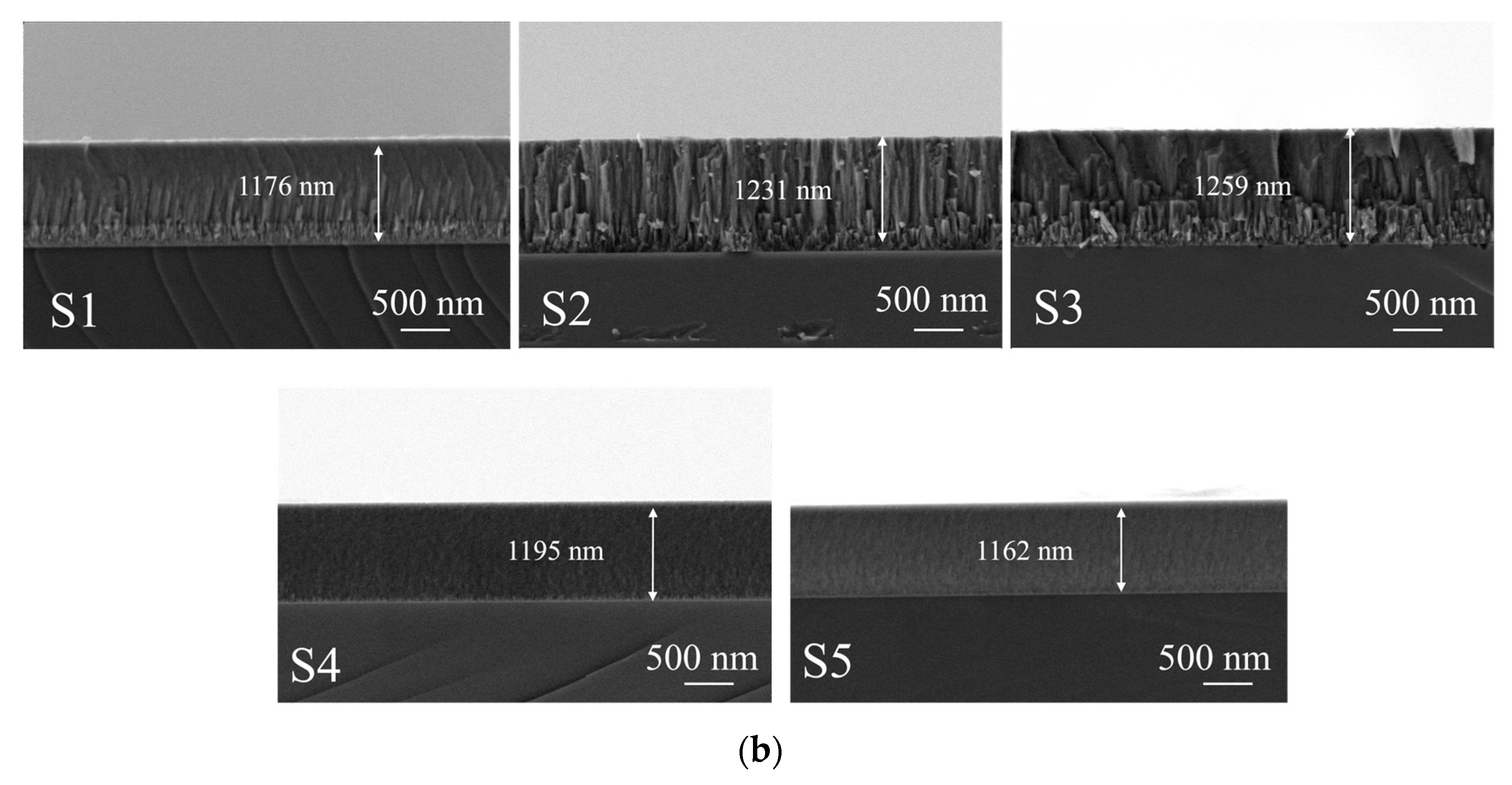
Figure 1a shows the SEM surface morphology of the (AlTiVCrNb)CxNy coating under different deposition bias conditions. According to the surface morphology of the coating, the surface roughness and density of the (AlTiVCrNb)CxNy coating are improved with the increase in the Zc value under different Zc values. This is because under the effect of the matrix bias, the ion beam with a high ionization rate can be precisely regulated, and the ion beam energy on the coating surface can be effectively regulated. When the Zc value is 0 V, the surface flatness of the coating is poor, and the particle size difference of the coating is large. When the Zc value increased from 30 V to 60 V, the deposited ions reached the substrate surface with higher energy, and the loosely bound atoms on the surface of the coating were peeled off via reverse sputtering. The surface roughness of the coating improved, the grains were refined, and the density of the coating increased. When the Zc value increased to 90 V, the surface of the coating was smooth, and the surface of the coating prepared under the biased pressure condition showed excellent densification [16], indicating that the crystallization property of the coating significantly improved. When the Zc value was 120 V, the density of the coating decreased, and large particles appeared on the surface of the coating. Figure 1b shows the SEM cross-sectional morphology of (AlTiVCrNb)CxNy coatings under different deposition bias conditions. The cross-section morphology shows that the coating structure is a columnar crystal, and the columnar crystal size decreases first and then increases with the change in the Zc value. The deposition rate of the coating is related to the ion bombardment and deposition mechanism of the pulsed bias during the deposition process. When the bias is low, the atoms and ions are mainly involved in the deposition, and the sputtering effect is weak. Increasing the bias voltage can increase the energy of the deposited ions and the deposition rate of the coating. When the bias voltage continues to increase, the sputtering effect is enhanced so that the unfilmed atoms adsorbed on the substrate are sputtered, resulting in a decrease in the deposition rate. In addition, the lower bias voltage is conducive to the agglomeration of large particles [18], thereby increasing the deposition rate, resulting in a loose and porous coating structure and reducing the compactness of the coating. When the Zc value increases to 90 V, the coating exhibits a dense columnar crystal structure [19]. Under the continuous bombardment of high-density charged ions on the surface of the coating, the columnar crystals are interrupted by high-energy ion beams during the growth process. They re-nucleate and continue to grow, thereby forming a fine and dense columnar crystal structure.

3.2. Coating Structure Analysis

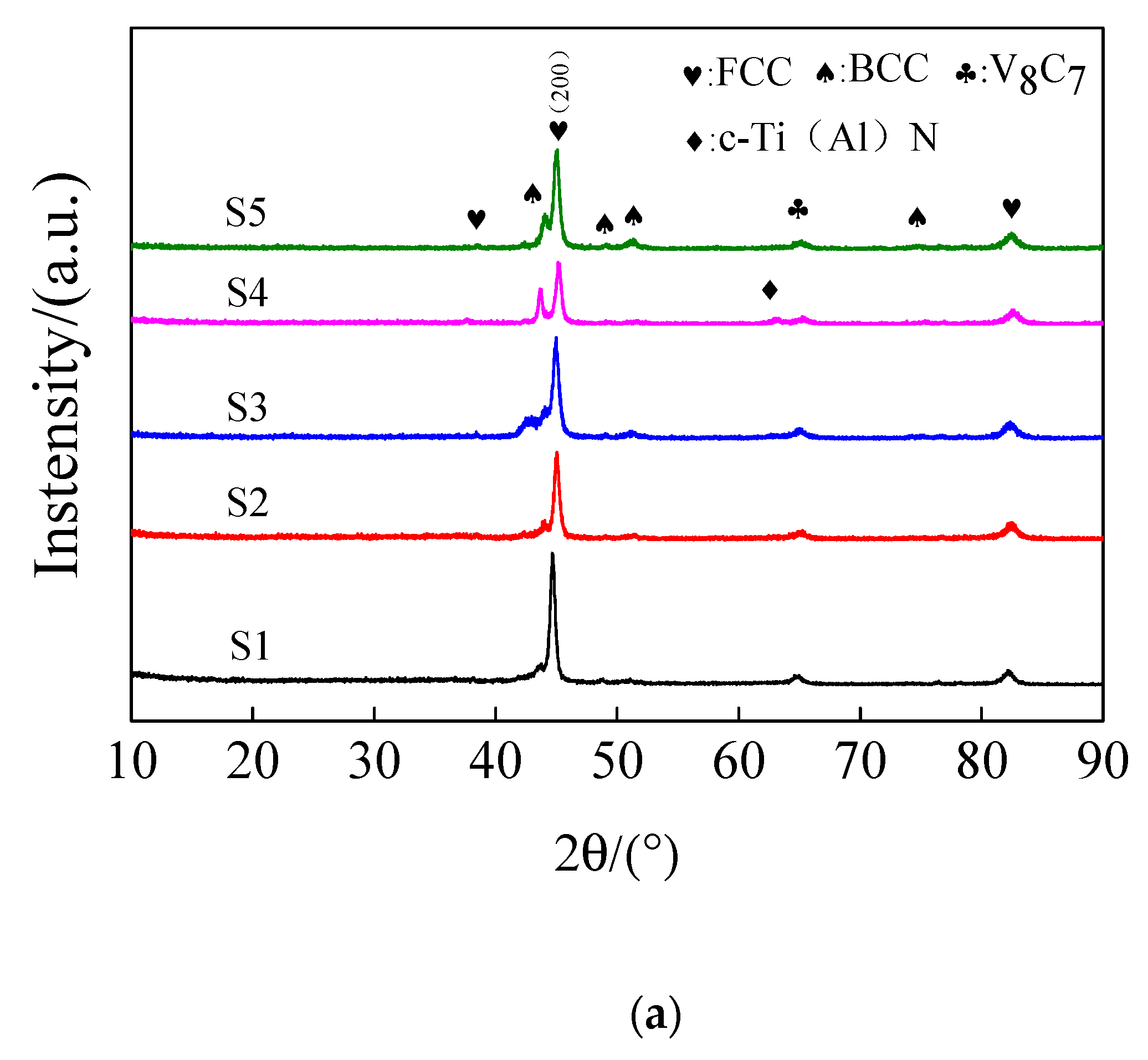
Figure 2a shows the XRD spectra of the coating at different Zc values. The diffraction peaks of (200), V8C7, and c-Ti (Al) N crystal faces can be observed in the diffraction spectra of the coating. The diffraction peaks of each crystal face of the coating are widened, showing a nanocrystalline structure. When the Zc value rises to 90 V, the diffraction peaks of (111) in the coating and c-Ti (Al) N crystal surface in the coating increase in shape and intensity. The high-density charged ions continuously bombard the film-forming surface, resulting in an atomic-scale heating effect on the growing coating surface [20], and the increase in the matrix temperature helps improve the crystallization properties of the coating. Among them, the S4 coating affects the grain growth mode in the coating due to the formation of different compound crystals, which in turn affect the density of the coating.
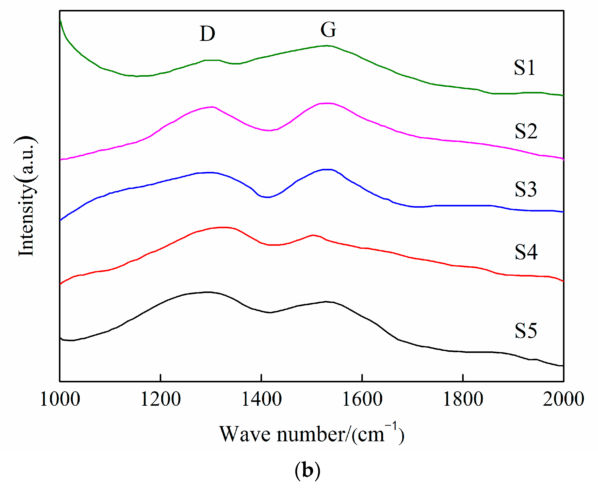
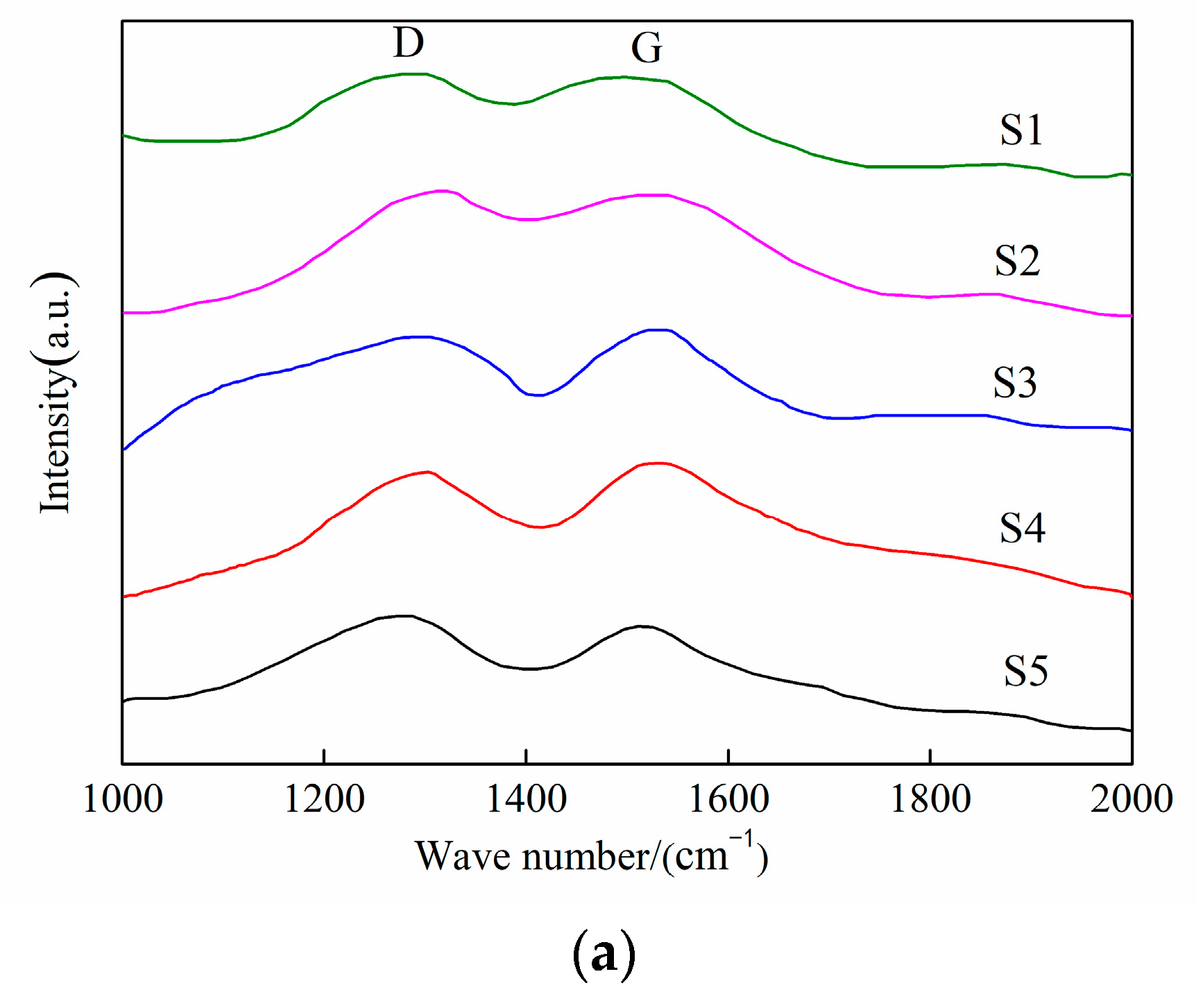
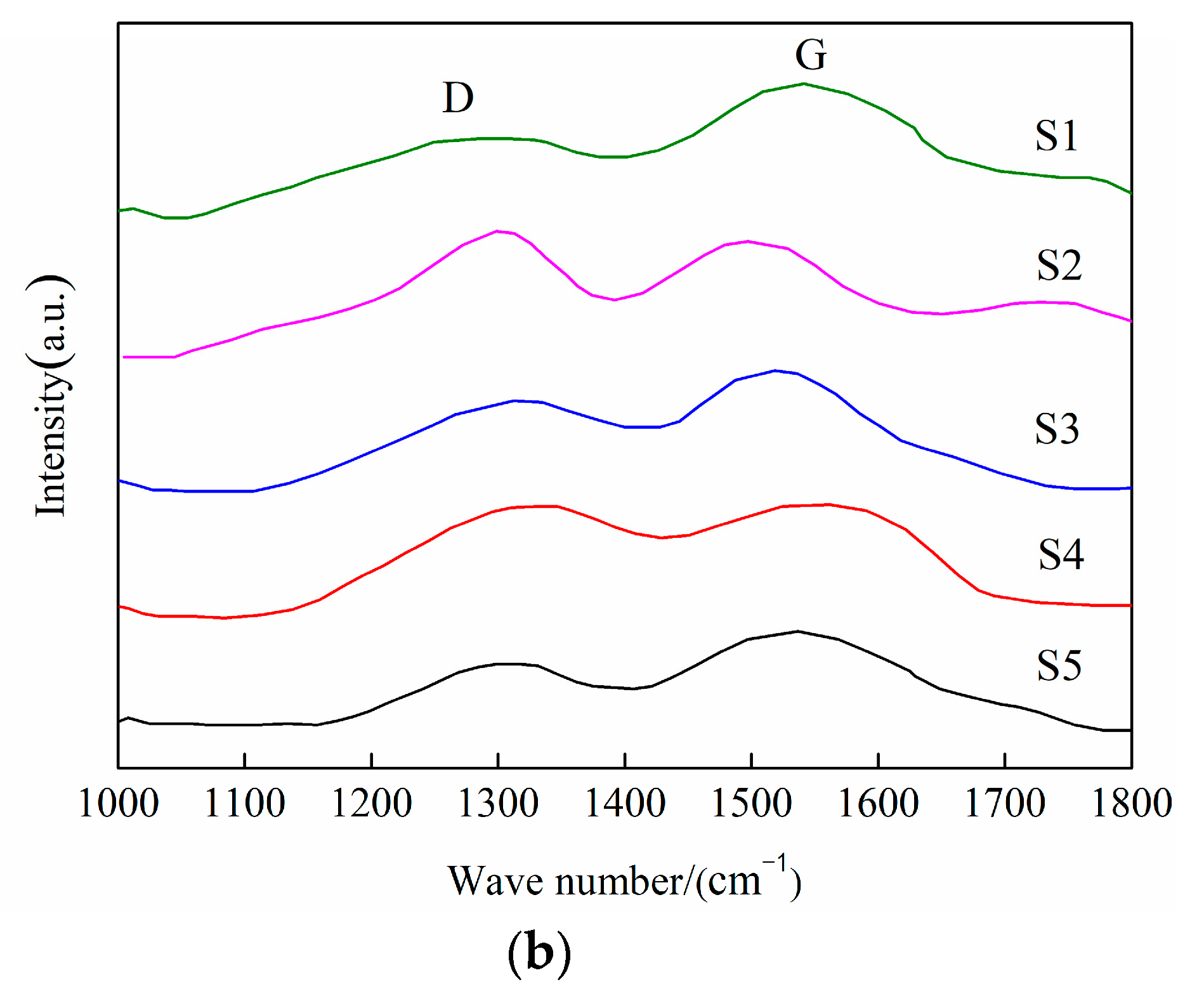
Figure 2b shows the Raman spectra of (AlTiVCrNb)CxNy coatings at different Zc values. The Raman spectrum mainly comprises a D peak near 1360 cm−1 and a G peak near 1560 cm−1. The in-plane stretching vibration of all ring or chain sp2 states in the coating is the main source of the G peak. The D peak is derived from the respiratory vibration of the sp2 state of the ring structure, highlighting the formation of graphite rings in the sp2 cluster. The half-peak full width of peak G corresponds to the structural disorder caused by the disorder of the bond length and bond angle [21], and the increase in sp2 content can increase the size of the hexagonal ring shape, thereby reducing the structural disorder, which is one of the reasons for the dense structure of the coating. The signal of the D peak and G peak can be observed in the Raman spectrum. The results show that the crystalline phase of the coating changes with the change in the Zc value, and the (AlTiVCrNb)CxNy coating contains an amorphous carbon phase. The results show that the (111) diffraction peak and c-Ti (Al) N crystal peak appear in the coating when the Zc value is 90 V. The coating mainly comprises Face-Centered Cubic, the Body-Centered Cubic crystal phase, and a small amorphous carbon phase. Moreover, the crystal phase composition of the coating is affected by the change in the Zc value.
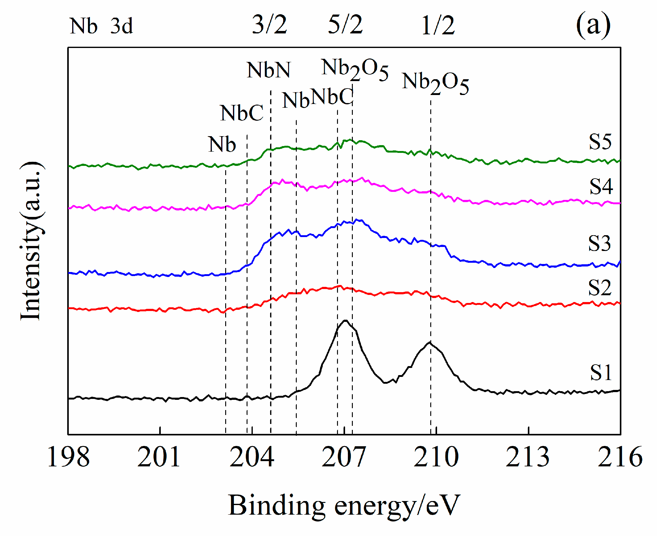
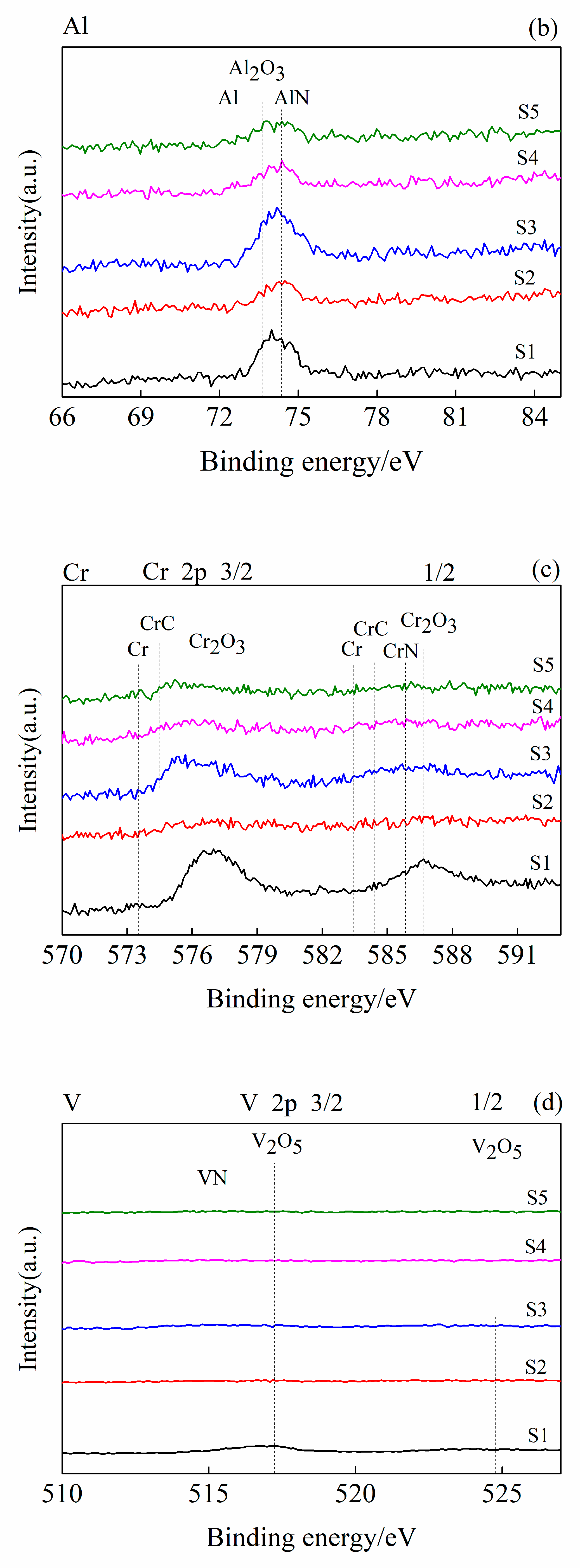
In order to further study the chemical state of elements in the coating (AlTiVCrNb)CxNy, an XPS test was carried out on the coating (AlTiVCrNb) CxNy, and the chemical forms of five metal elements and carbon were calibrated through NIST XPS database and the literature [22,23,24]. Figure 3a shows the high-resolution spectrum of Nb 3d of (AlTiVCrNb)CxNy coating. In the figure, Nb on the surface of the coating combines with carbon to form carbide NbC, part of which exists in the form of NbN and Nb2O5 (205.31, 207.68 and 210.32 eV [22,24]), and a small part of Nb exists in a metallic state. Figure 3b shows that Al exists in the form of Al2O3 and AlN (74.61, 74.7 eV [22]) on the surface of the coating, and a small part of Al exists in the metallic state. The figure shows that with the increase in the Zc value, the peaks of Nb3d5/2 and Al2p1/2 move toward higher binding energy, indicating that they react with oxygen and their chemical valence states increase. Figure 3c shows that under the influence of different Zc values, when the Zc value is 90 V, carbon reacts with Cr to form CrC, and the rest exists in the form of metallic Cr, nitride CrN, and oxide Cr2O3 (579.99, 586.59 eV [23]). In Figure 3d, the V2p1/2 peak does not change with the increase in the Zc value, indicating that the change in the Zc value has little influence on it, which is similar to Nb. Figure 3e shows that, with an increase in the Zc value, TiC begins to be generated in the coating, and the remaining Ti exists in the form of TiC and TiO2 (455 and 461.12, 464.57 eV [22]) and part of Ti exists in the form of a metal state. With the increase in the Zc value, the peak of Ti2p3/2 shifts to a high binding energy. This shows that it reacts with carbon and oxygen and its chemical valence state increases. Figure 3f of the C1s peak shows that there are sp3 state C-C and sp2 state C=C in the coating, indicating that there are a carbide ceramic phase and amorphous carbon phase in the coating. When the deposition bias of (Al Ti VCr Nb) CxNy coating is 0 V, the main form of Nb in the coating is Nb2O5, the main form of Cr is Cr2O3, and the main form of Ti is TiN. The reason for this is that the deposition rate of the coating is related to the ion bombardment and the deposition mechanism of the pulse bias during the deposition process. When the bias voltage is 0 V, the atoms and ions are mainly involved in the deposition, and the sputtering effect is weak. As the bias voltage increases, the energy of the deposited ions increases, and the deposition rate of the coating decreases, which affects the elemental composition of the coating. According to the above analysis results, the metal element reacts with oxygen to form an oxide on the surface of the coating, which is consistent with the XRD analysis results in Figure 2a, indicating that there is a small amount of oxide in the coating. Due to the difference in mixing enthalpy between carbon and other metal elements [25], the mixing enthalpy acts as a driving force to promote the combination of Nb, Cr, and Ti with carbon to form an FCC ceramic phase, thus affecting the composition fluctuations in the coating, while V and Al form an amorphous phase with the remaining Nb, Cr, Ti, and C. In addition, when the Zc value is 90 V, the carbon in the coating exists in the form of sp2 state C=C and sp3 state C-C. Previous studies have shown that the increase in sp2 structure (graphitization) can reduce the friction force between friction contact surfaces and affect the friction coefficient. This also indicates that the change in the Zc value affects the form of carbon in the coating, thus affecting the microstructure and tribological properties of the coating.

3.3. Hardness and Elastic Modulus Analysis

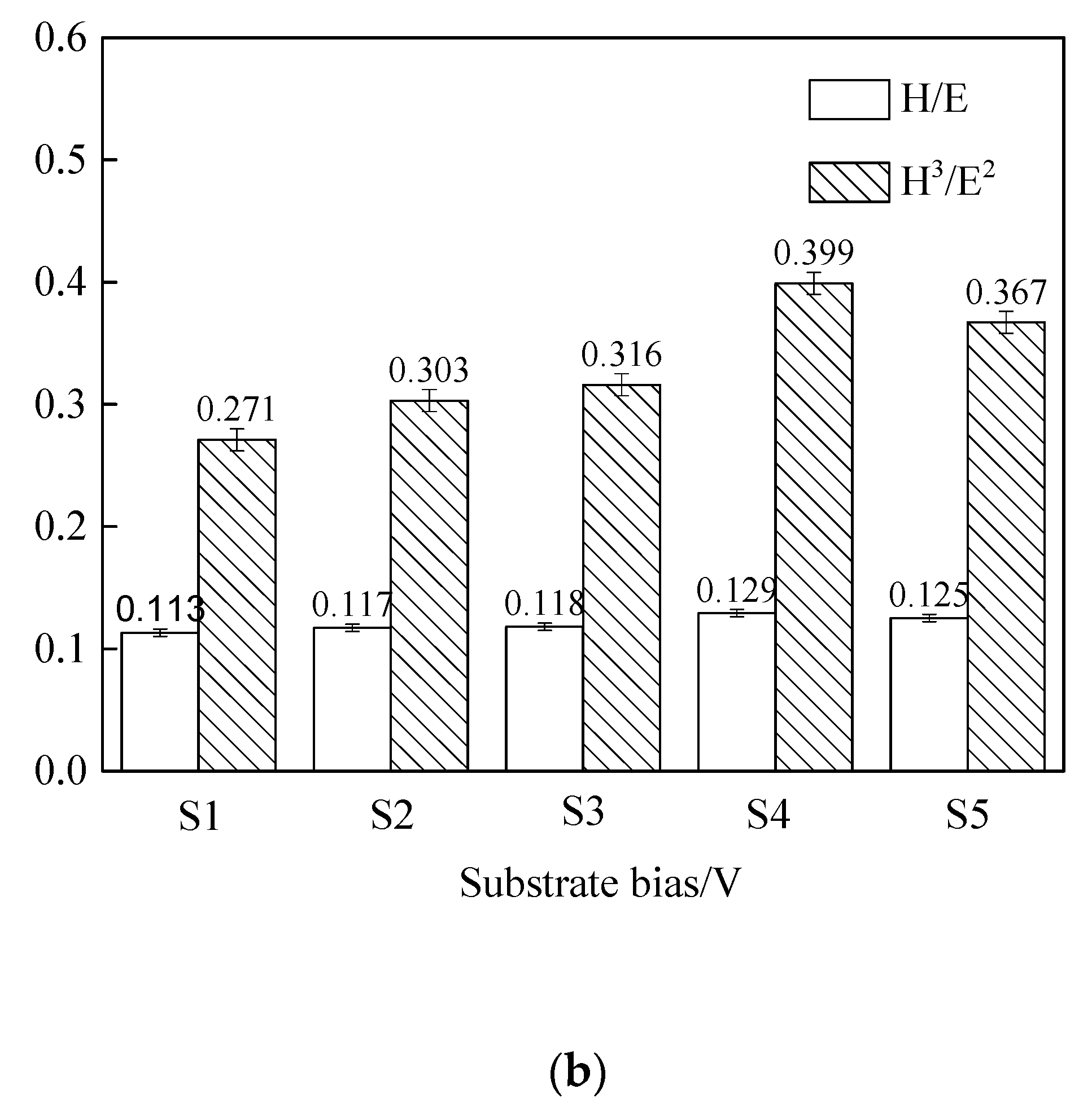
Figure 4 shows the hardness H and elastic modulus E, H/E (anti-plastic deformation index), and H3/E2 (anti-elastic deformation index) values of the (AlTiVCrNb)CxNy coating under different Zc values. With the increase in the Zc value, the hardness of the coating increases first and then decreases. When the Zc value is 90 V, the maximum hardness of the coating is 23.98 GPa. The linear relationship between the elastic modulus of the prepared coating and the bias parameter is not obvious under different bias conditions. When the bias pressure is 90 V, the elastic modulus of the coating reaches the minimum value of 184.8 GPa. During the deposition process, a highly ionized deposited ion beam without large particles is formed, and the beam reaches the coating surface at a high speed under the bias of the matrix. With the increase in bias pressure, the bombardment effect of charged ions on the coating surface is enhanced [26], which is conducive to the formation of a compact and flat nanocrystalline coating structure. Therefore, with the increase in the Zc value, the hardness value increases gradually. According to the SEM analysis of the coating, when the bias value is about 90 V, the densification and grain refinement of the coating can be significantly improved. In addition, the continuous high-energy particle bombardment gives the deposited ions enough energy to complete the amplitude modulation decomposition of the nanocrystalline and amorphous phases. Thus, the formation of nanocomposite structures can improve the hardness and toughness of the coating simultaneously. When the Zc value is 90 V, the mechanical properties of the coating are the best—the H/E value is 0.129, H3/E2 is 0.399—and it has excellent plastic deformation resistance. On the one hand, the ion beam increases the migration rate and distance of deposited ions under a higher bias [27].
Due to the change in the deposition bias value, the number and probability of a collision of the sputtering peak of atoms before reaching the matrix are affected, which further affects the grain size and leads to lattice distortion [28], thus affecting the dislocation slip deformation in the grains and the fine grain strengthening effect. In addition, according to the Hall–Petch relationship [28], the increase in coating hardness is related to the decrease in grain size. As the bias voltage increases, the deposition rate of the coating gradually decreases. This is because the atomic energy at a low bias is lower and it is easier to deposit on the substrate surface. However, as the bias voltage increases, the Al, Cr, and Ti atoms from the sputtering target to the substrate have higher kinetic energy and more atoms on the surface will be sputtered again to inhibit the growth of the film. The change in the grain orientation and grain refinement of the coating also affects its hardness. The grains with the same crystal structure but different growth orientations meet to form grain boundaries. The discontinuity of the slip surface between the grain boundaries and the grains hinders the dislocation movement and slip, which affects the hardness of the coating.
On the other hand, the crystallization properties of the coating are obviously improved due to the atomic heating effect. Combined with XRD and SEM analysis, the prepared coating shows a dense columnar crystal structure under this condition, which significantly affects its mechanical properties.

3.4. Tribological Performance Analysis

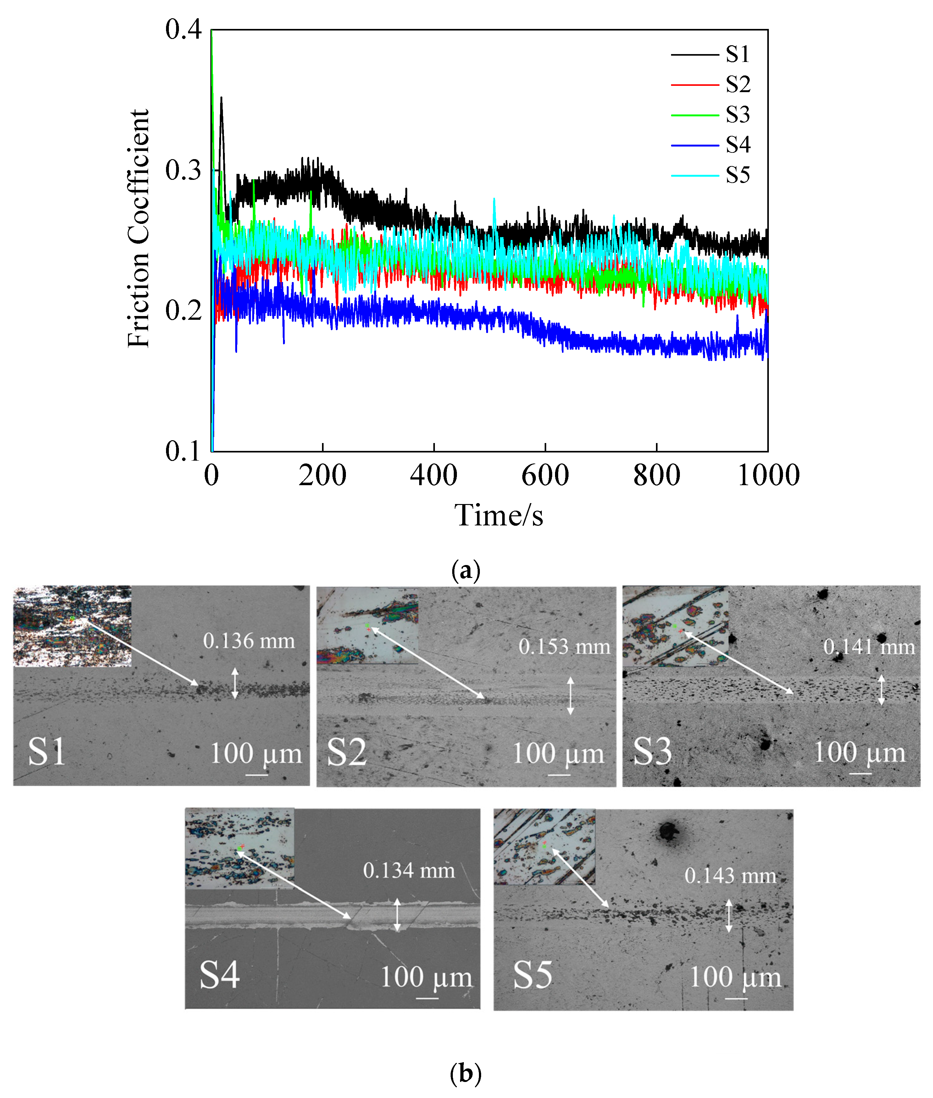
The change trend of the friction coefficient curve of (AlTiVCrNb)CxNy coating is shown in Figure 5a. Because the contact stage between the coating and the friction pair is the “irregular” micro-convex interaction at the initial time, the contact stress causes the friction coefficient to rise. Then, a relatively stable friction coefficient is formed. The results show that the highest average friction coefficient of the coating is 0.261, and the lowest average friction coefficient is 0.185. According to the above analysis, due to the influence of different Zc values, when the Zc value is 90 V, the dense structure of S4 coating has a great influence on the tribological performance of the coating. The coating S1 and S2 show loose columnar growth structures, as shown in Figure 1b. In Figure 2a XRD, the (200) crystal peak value is also large, indicating that its grain size is large, which is also the reason for the influence of its tribological performance. In order to further analyze the friction and wear mechanism of the coating, the wear morphology of the surface of the coating (AlTiVCrNb)CxNy was observed via scanning electron microscopy, as shown in Figure 5b. The wear of coating S1 is relatively serious, and obvious grooves and scratches of the coating are observed during the wear process, which proves that abrasive wear is its main wear mechanism. The minimum wear width of the coating S4 is 0.134 mm, and there are pits and small patches in the wear marks, typical characteristics of adhesive wear. The wear marks of coatings S2 and S5 are relatively wide, with the maximum width of S2 being 0.153 mm. In addition, there are a small number of pits, patches, and small transverse cracks in the wear marks of coatings S3 and S5, indicating that the wear surface experienced the periodic accumulation of wear chips and local fractures. In addition, obvious grooves and scratch marks can be observed in the wear marks, indicating that abrasive [29] and adhesive wear [30] occur on the coating.
D and G peaks appeared in the Raman spectra of the samples. The appearance of D and G peaks indicates that the friction products contain amorphous carbon-based films. This is because the friction process generates a carbon-based film with a lubricating effect at the interface. The intensity ratio of the D peak to the G peak (ID/IG) reflects the degree of graphitization. The larger the ID/IG is, the higher the degree of graphitization. Graphite is a layered structure, which easily shears during the friction process, resulting in a lubricated friction interface, which can effectively reduce the friction force. Figure 5b shows that the coating prepared when the bias voltage is 0 is seriously worn, with a large number of furrows appearing on the wear marks and abrasive wear. This is due to the cutting of the matrix by the hard products formed during the friction process under the action of tangential force. When the bias voltage is high, a small amount of shallow furrows appear on the wear scar of the coating. With the increase in bias voltage, when the bias voltage is 90 V, the wear scar width decreases, and the wear resistance of the coating increases, which is related to the smooth surface and high hardness of the coating [12].
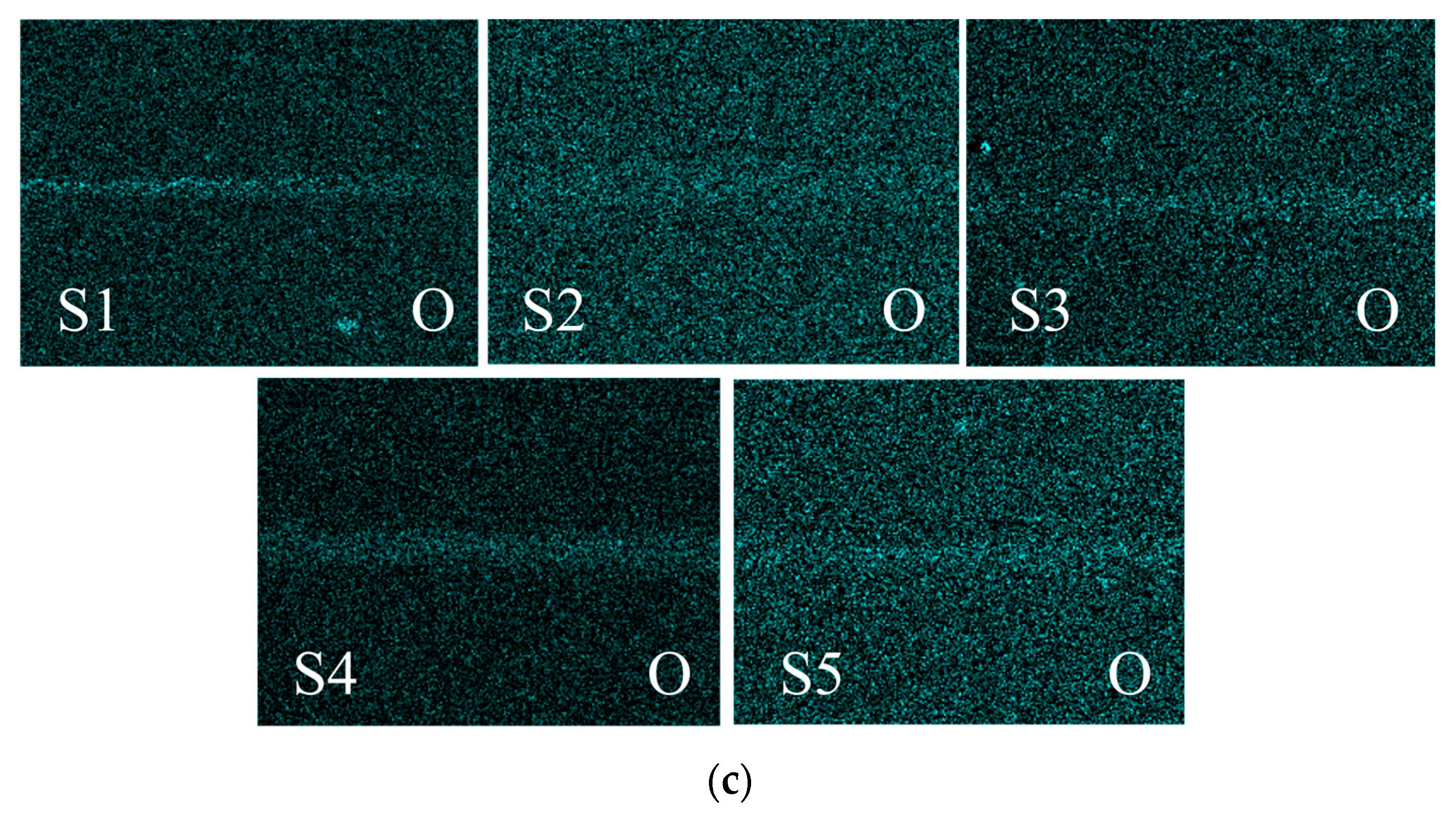
In addition, when analyzing the chemical composition of the wear scar surface, as shown in Figure 5c, oxygen was found. This shows that during the friction process in the (AlTiVCrNb)CxNy coating, heat is generated due to friction and the coating deformation, resulting in oxidation of the coating surface. These results show that there is an oxidative wear mechanism in the coating. This is because there are more metal phases in the coating. During the friction process, the metal phase easily oxidizes into an oxide structure, and the formation of the oxide layer can avoid direct contact between the coating and the counterbody, thereby improving the wear resistance of the coating. In the figure, there are fewer oxygen elements at the wear marks of S1 and S5 coatings, indicating that the oxidative wear mechanism of the coating is weak. The increase in oxygen at the wear mark of the coating S4 indicates that the oxidative wear mechanism is relatively enhanced [31]. The formation of the oxide layer on the surface of the contact pair during the wear process improves the wear resistance of the coating.
Figure 6 shows a picture of the wear scar of the steel ball, in which the steel ball has obvious friction loss. The wear scar morphology shows that the wear scar width of the S4 pattern is the narrowest, only 163.3 μm. During the friction process, some of the flaked chips are crushed to the bottom of the wear scar, and the other part is squeezed to the outside of the wear scar. At this time, the formation of a transfer film on the dual surface of the counterbody plays a lubricating role, which is also why coating S4 has a better friction coefficient. The Raman at the coating wear mark in Figure 7a shows that obvious D-peak and G-peak signals appear in the coating wear mark Raman map. In Figure 7b showing Raman detection of the wear tracks on the balls, there are also D-peak and G-peak signals of different strengths at the parts of the wear tracks on the balls. The results show that with the progress of friction, the micro convex on the surface of the coating is gradually worn down, and the sp2 clusters in the coating are cut off from the surface of the coating during the friction process. Some of them remain at the position of the wear mark, and some stick to the counterbody to form a transfer film. This carbon transfer film formed during the coating wear process can effectively prevent direct contact between the coating and the counterbody, thereby reducing the friction coefficient and forming stable friction. The reason for this is that after the friction and wear test, the hard points in the coating bulge outward, while the soft parts concave inward. Small gaps can be formed between the sliding surfaces, which is conducive to forming a high-quality transfer film. The distribution of elements in Figure 6 shows that the transfer film mainly exists in two forms, namely, the oxide layer formed on the contact surface and the carbon transfer film. The coating mainly forms V2O5 in the Magnéli phase [32], which has an anti-friction effect. Al2O3, Cr2O3, and Nb2O5 easily form dense oxides. When the load is 5 N during the friction process, the worn steel ball hinders the movement of the oxide and slows down the consumption rate of the lubricating phase and the wear-resistant phase. At the same time, the interlayer slip performance between the coating and the counterbody plays a role in reducing friction and wear performance, which leads to the improved wear performance of the coating. The coating presents a low and stable friction coefficient and mechanical properties, partly because the hard points raised during wear have a better supporting effect [28], which can improve the bearing capacity of the coating. The S4 coating has a low and stable friction coefficient, indicating that the transfer film is formed better during the process of coating friction and wear. The reason for this is that the change in the Zc value affects the density structure of the coating and affects the formation quality of the transfer film.
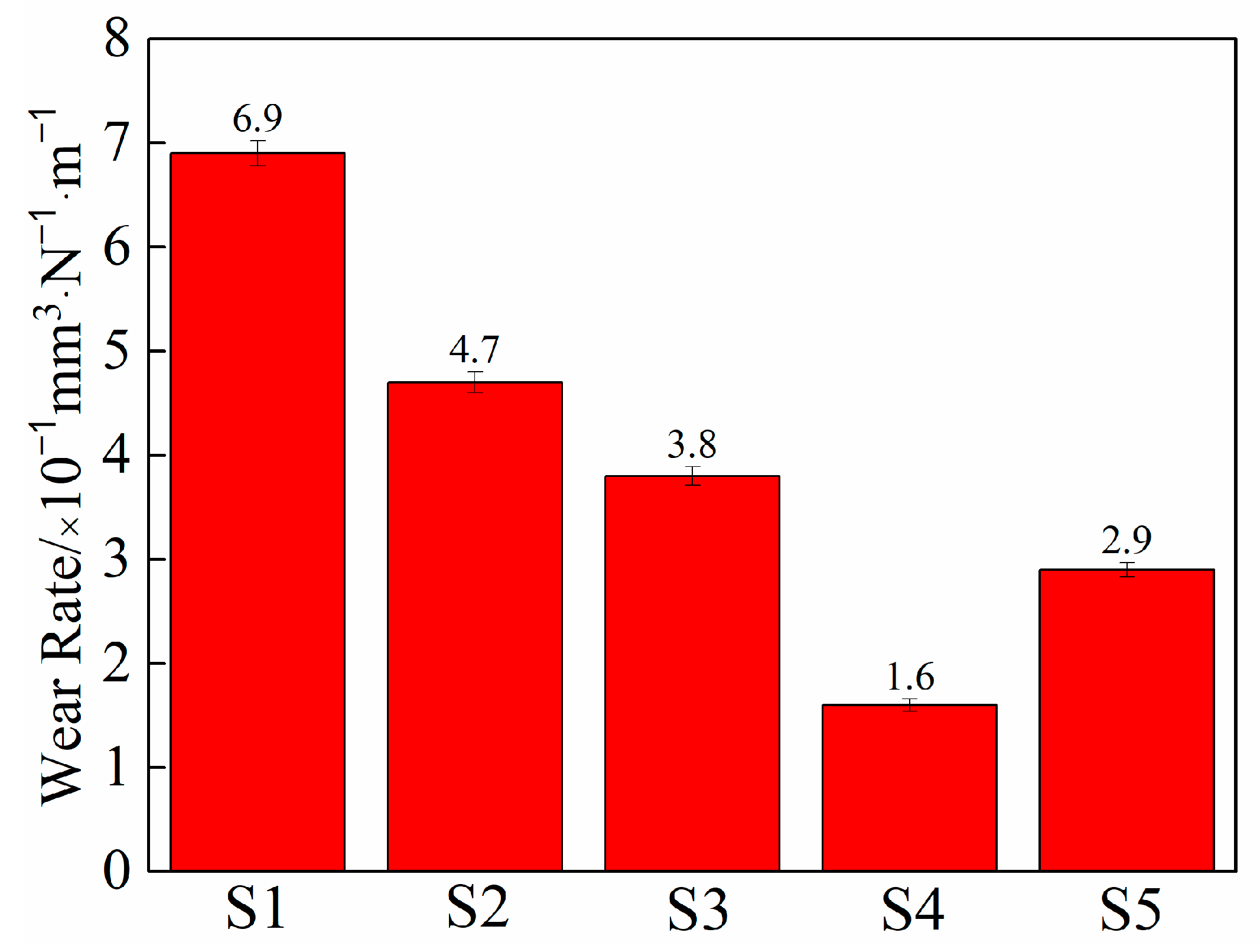
The wear rate of (AlTiVCrNb)CxNy coating is shown in Figure 8. The figure shows that the wear rate of the coating and the friction coefficient have similar change rules, and the wear rate of coating S1 is the largest, reaching 6.9 × 10⁻⁷ mm3/N·m. On the one hand, the oxidation wear mechanism at the wear mark of coating S1 is weak; on the other hand, the microstructure of the coating is loose, and the external stress is concentrated during the friction process, so the wear rate is also high. The wear rate of coating S4 is the lowest, 1.6 × 10⁻⁷ mm3/N·m. The analysis shows that when the Zc value is 90 V, the density of the coating is the best, the hardness and elastic modulus are also large, the small pores between the particles are reduced, and the bearing capacity of the coating is enhanced. The wear rate of coating S2 is 4.7 × 10⁻⁷ mm3/N·m and that of coating S3 is 2.2 × 10⁻⁶ mm3/N·m. The wear rate of coatings S2 and S3 is relatively lower than that of coating S1, and the reason for this is that the oxidation wear mechanism at the wear marks of coatings S2 and S3 is relatively strong. In addition, the carbide crystal phase and a small amount of amorphous carbon phase formed in the coating affect the microstructure of the coating and then the friction and wear properties of the coating.
Due to the progress of friction, the asperities on the surface of the coating were gradually smoothed, and the sp2 clusters in the coating were cut off from the surface of the coating during the friction process. Some of them remained in the wear scar position, and some were ground to form a transfer film on the counterbody. The carbon transfer film formed during the wear process of the coating can effectively prevent direct contact between the coating and the counterbody, thereby reducing the friction coefficient and forming stable friction. The reason for this is that increasing the bias conductance weakens the lattice distortion inside the coating structure, resulting in a decrease in internal stress. High-energy ion bombardment promotes the formation of surface and subsurface defects (such as ion implantation and point defects). Therefore, a small gap can be formed between the sliding surfaces, which will benefit the formation of high-quality transfer films. There are two main forms of transfer film: oxide film and carbon transfer film formed on the surface of the contact pair. The coating exhibits a low and stable friction coefficient and mechanical properties. Part of the reason for this is that the protruding hard particles will have a good supporting effect during the wear process, which can improve the bearing capacity of the coating. In the process of friction, (AlTiVCrNb)CxNy coating forms a carbon transfer film on the dual surface of the counterbody during wear, which is also the reason for the low wear rate of the (AlTiVCrNb)CxNy coating when the Zc value is 90 V. The above results show that the coating has excellent wear resistance when the Zc value is 90 V.

4. Conclusions

(1) The phase of (AlTiVCrNb)CxNy coating comprises FCC ceramic, amorphous alloy, amorphous carbon, and carbide nanocrystalline phases. The change in the matrix bias has a great influence on the structure and properties of the (AlTiVCrNb)CxNy coating. With the increase in matrix bias pressure, the microstructure of the coating changes, and the density of the coating increases first and then decreases. The density of the coating is optimal when the Zc value is 90 V.
(2) With the change in substrate bias, the hardness of the (AlTiVCrNb)CxNy coating increases first and then decreases, and the coating has excellent tribological properties and good friction and wear properties. When the Zc value is 90 V, the maximum hardness of the coating is 23.98 GPa, the elastic modulus is 184.8 GPa, and the average friction coefficient and wear rate of the coating are 0.185 and 1.6 × 10⁻⁷ mm3/N·m, respectively, which indicate excellent plastic deformation resistance.
(3) There is abrasive and adhesive wear in the wear process of the coating, and the oxidation wear is accompanied by the contact part of the counterbody. The oxidation film is generated on the surface of the contact pair, and the sp2 cluster in the coating forms a carbon transfer film on the dual surface of the counterbody during the wear process, thereby improving the tribological performance of the coating.

Author Contributions

Conceptualization, Y.X.; data curation, H.C.; formal analysis, P.G.; project administration, H.C. and L.P.; resources, Y.X.; writing—original draft, H.C. and L.P.; writing—review and editing, J.Y. and Y.Z. All authors have read and agreed to the published version of the manuscript.

Funding

This research was funded by the National Key Research and Development Program, grant number 2021YFB3400400, and the Project of Science and Technology Development of Henan Province, grant number 232102220047.

Data Availability Statement

The authors confirm that the data supporting the findings of this study are available within the article.

Conflicts of Interest

Author Pengge Guo was employed by the company Luoyang Bearing Group Co. The remaining authors declare that the research was conducted in the absence of any commercial or financial relationships that could be construed as a potential conflict of interest.

References

  1. Nie, H.; Zeng, S.; Nie, J.; Lai, C. Effect of VC Addition on microstructure and properties of Laser cladding Fe50Mn30Cr10Co10 High Entropy alloy coating. Mater. Mech. Eng. 2019, 47, 7–11. [Google Scholar]
  2. Yang, Y.; Zhang, Y.; Li, J.; Zhu, H.; Zhang, J. Research status of high entropy alloying. Metall. Eng. 2021, 8, 10. [Google Scholar]
  3. Li, X.; Wang, Y.; Zhang, J.; Wu, K.; Liu, G.; Sun, J. Research progress of High-entropy alloy coating. Surf. Technol. 2023, 52, 1–20. [Google Scholar]
  4. Ragachev, A.; Yarmolenko, M.; Rogachev, A.; Gorbachev, D.; Zhou, B. Chemical composition, morphology and optical properties of zinc sulfide coatings deposited by low-energy electron beam evaporation. Appl. Surf. Sci. 2014, 303, 23–29. [Google Scholar] [CrossRef]
  5. Wang, H.; Zhuang, D.; Wang, K.; Liu, J.; Fang, X.; Li, Y. Microstructures and wear-resistance behaviors of ferrous sulfide coatings. Acta Metall. Sin.-Chin. Ed. 2003, 39, 1031–1036. [Google Scholar]
  6. Kang, C.; Jeon, B.; Kumar, R.; Park, S.; Park, H.; Kim, S. Stability of Coatings on Sulfide Minerals in Acidic and Low-Temperature Environments. Mine Water Environ. 2017, 36, 436–442. [Google Scholar] [CrossRef]
  7. Liang, H.; Qiao, D.; Miao, J.; Cao, Z.; Jiang, H.; Wang, T. Anomalous microstructure and tribological evaluation of AlCrFeNiW0.2Ti0.5 high-entropy alloy coating manufactured by laser cladding in seawater. Mater. Sci. Technol. 2021, 85, 224–234. [Google Scholar] [CrossRef]
  8. Li, J.; Peng, Z.; Ma, M.; Lu, J.; Wu, Y. Effect of CeO2 on microstructure and hardness of AlCoCuFeMnNi high-entropy alloy coating. Jinshu Rechuli/Heat Treat. Met. 2017, 42, 19–23. [Google Scholar]
  9. Zhang, Y.; Han, T.; Xiao, M.; Shen, Y. Preparation of Diamond Reinforced NiCoCrTi0.5Nb0.5High-Entropy Alloy Coating by Laser Cladding: Microstructure and Wear Behavior. J. Therm. Spray Technol. 2020, 29, 1827–1837. [Google Scholar] [CrossRef]
  10. Wang, J. Effect of Y on Microstructure and Properties of Al0.8FeCrCoNiCu0.5 High Entropy Alloy Coating on 5083 Aluminum by Laser Cladding. Lubricants 2023, 11, 50. [Google Scholar] [CrossRef]
  11. Guo, Y.; Liu, Q.; Zhou, F. Microstructure and Wear Resistance of High-Melting-Point AlCrFeMoNbxTiW High-Entropy Alloy Coating by Laser Cladding. Chin. J. Rare Met. 2017, 41, 1327. [Google Scholar]
  12. Zhang, Y.; Han, T.; Xiao, M.; Shen, Y. Tribological behavior of diamond reinforced FeNiCoCrTi0.5 carbonized high-entropy alloy coating. Surf. Coat. Technol. 2020, 401, 126233. [Google Scholar] [CrossRef]
  13. Liu, J.; Liu, H.; Di, Y.; Lin, J.; Hao, X.; Wang, Y.; Chen, L.; Zhang, X. Effect of Carbon Content on friction, wear and corrosion resistance of Laser cladding CoCrFeMnNiCx high entropy alloy coating. China Surf. Eng. 2019, 33, 118–127. [Google Scholar]
  14. Xin, B.; Zhang, A.; Han, J.; Meng, J. The tribological properties of carbon doped Al0.2Co1.5CrFeNi1.5Ti0.5 high entropy alloys. Wear 2021, 484, 204045. [Google Scholar] [CrossRef]
  15. Che, L.; Liu, J.; Peng, F.; Xiong, H.; Zhang, F.; Ma, X.; Gao, N.; Liu, X. Effect of C alloying on microstructure and tensile properties of AlCrFeCoNi2.1 eutectic high entropy alloy. J. Netshape Form. Eng. 2022, 8, 14. [Google Scholar]
  16. Zhuang, D.; Tao, W.; Ni, H.; Wang, A.; Du, B.; Zhang, S.; Lian, X. TiC morphology and corrosion resistance of CrMnFeCoNi+x(TiC) coatings prepared by laser cladding. Mater. Charact. 2023, 205, 113339. [Google Scholar] [CrossRef]
  17. Muhammad Nadzri, N.; Halin, D.; Al Bakri Abdullah, M.; Joseph, S.; Mohd Salleh, M.; Vizureanu, P.; Burduhos-Nergis, D.; Sandu, A. High-Entropy Alloy for Thin Film Application: A Review. Coatings 2022, 12, 1842. [Google Scholar] [CrossRef]
  18. Barber, Z.H. The Structure of Vapor-Deposited Materials. Mater. Sci. Mater. Eng. 2016. [Google Scholar] [CrossRef]
  19. He, Q.; DePaiva, J.; Kohlscheen, J.; Beake, B.; Veldhuis, S. Study of wear performance and tribological characterization of AlTiN PVD coatings with different Al/Ti ratios during ultra-high speed turning of stainless steel 304. Int. J. Refract. Met. Hard Mater. 2021, 96, 102–110. [Google Scholar] [CrossRef]
  20. Alfonso, J.; Torres, J.; Marco, J. Influence of the substrate bias voltage on the crystallographic structure and surface composition of Ti6A14V thin films deposited by rf magnetron sputtering. Braz. J. Phys. 2006, 36, 994–996. [Google Scholar] [CrossRef]
  21. Li, Y.; Shi, Y.; Olugbade, E. Microstructure and process optimization of AlCrFeCoNiCu high-entropy alloy by laser deposition. Opt. Precis. Eng. 2019, 42, 184–195. [Google Scholar]
  22. Cheng, C.; Li, H.; Zhang, C.; Guo, C.; Li, J.; Zhang, H.; Lin, S.; Wang, Q. Effect of substrate bias on structure and properties of (AlTiCrZrNb)N high-entropy alloy nitride coatings through arc ion plating. Surf. Coat. Technol. 2023, 467, 129692. [Google Scholar] [CrossRef]
  23. Dai, C.; Fu, Y.; Guo, J.; Du, C. Effects of substrate temperature and deposition time on the morphology and corrosion resistance of FeCoCrNiMo0.3 high-entropy alloy coating fabricated by magnetron sputtering. J. Miner. Metall. Mater. 2020, 27, 10. [Google Scholar] [CrossRef]
  24. Ivanov, Y.; Akhmadeev, Y.; Koval, N.; Shugurov, V.; Petrikova, E.; Krysina, O.; Prokopenko, N.; Tolkachev, O. Nitride Coatings Based on a High-Entropy Alloy Formed by the Ion-Plasma Method. High Energy Chem. 2023, 57 (Suppl. 1), S77–S80. [Google Scholar] [CrossRef]
  25. Lim, J.; Mimura, K.; Miyake, K.; Yamashita, M.; Isshiki, M. Effect of Substrate Bias Voltage on the Thermal Stability of Cu/Ta/Si Structures Deposited by Ion Beam Deposition. Jpn. J. Appl. Phys. 2003, 42, 2780–2785. [Google Scholar] [CrossRef]
  26. Hamzah, E.; Ali, M.; Toff, M. Effect of Substrate Bias on Friction Coefficient, Adhesion Strength and Hardness of Tin-Coated Tool Steel. Surf. Rev. Lett. 2006, 13, 763–771. [Google Scholar] [CrossRef]
  27. Cui, K.; Zhang, Y. High-Entropy Alloy Films. Coatings 2023, 13, 635. [Google Scholar] [CrossRef]
  28. Lin, J.; Zhang, X.; Ou, Y.; Wei, R. The structure, oxidation resistance, mechanical and tribological properties of CrTiAlN coatings. Surf. Coat. Technol. 2015, 277, 58–66. [Google Scholar] [CrossRef]
  29. Cai, H.; Xue, Y.; Wang, J.; Ye, J.; He, J. Effect of Sputtering Power on High Temperature Tribolo-gical Behavior of La-Ti/WS2 Composite Films. Rare Met. Mater. Eng. 2023, 52, 1201–1209. [Google Scholar]
  30. Wang, W.; Pelenovich, V.; Yousaf, M.; Yan, S.; Bin, H.; Wang, Z.; Tolstogouzov, A.; Kumar, P.; Yang, B.; Fu, D. Microstructure, mechanical and tribological properties of WC/a-C:H coatings deposited by cathodic arc ion-plating. Vacuum 2016, 132, 31–39. [Google Scholar] [CrossRef]
  31. Wu, R.; Zhang, Y.; Zhang, F.; Hou, B.; Liu, J.; Chen, Y.; Yang, S. Effect of Heat Treatment on Microstructure and properties of AlFeCoCrNiTi0.2 High entropy alloy. Nonferr. Met. Eng. 2019, 13, 41–48. [Google Scholar]
  32. Chang, W.; Cai, H.; Lei, X.; Xue, Y.; Li, H. High-temperature Tribological Properties of (AlCrNbTiVCe)N Coating Deposited by Co-sputtering Rare Earth Ce. Rare Met. Mater. Eng. 2023, 52, 527–534. [Google Scholar]
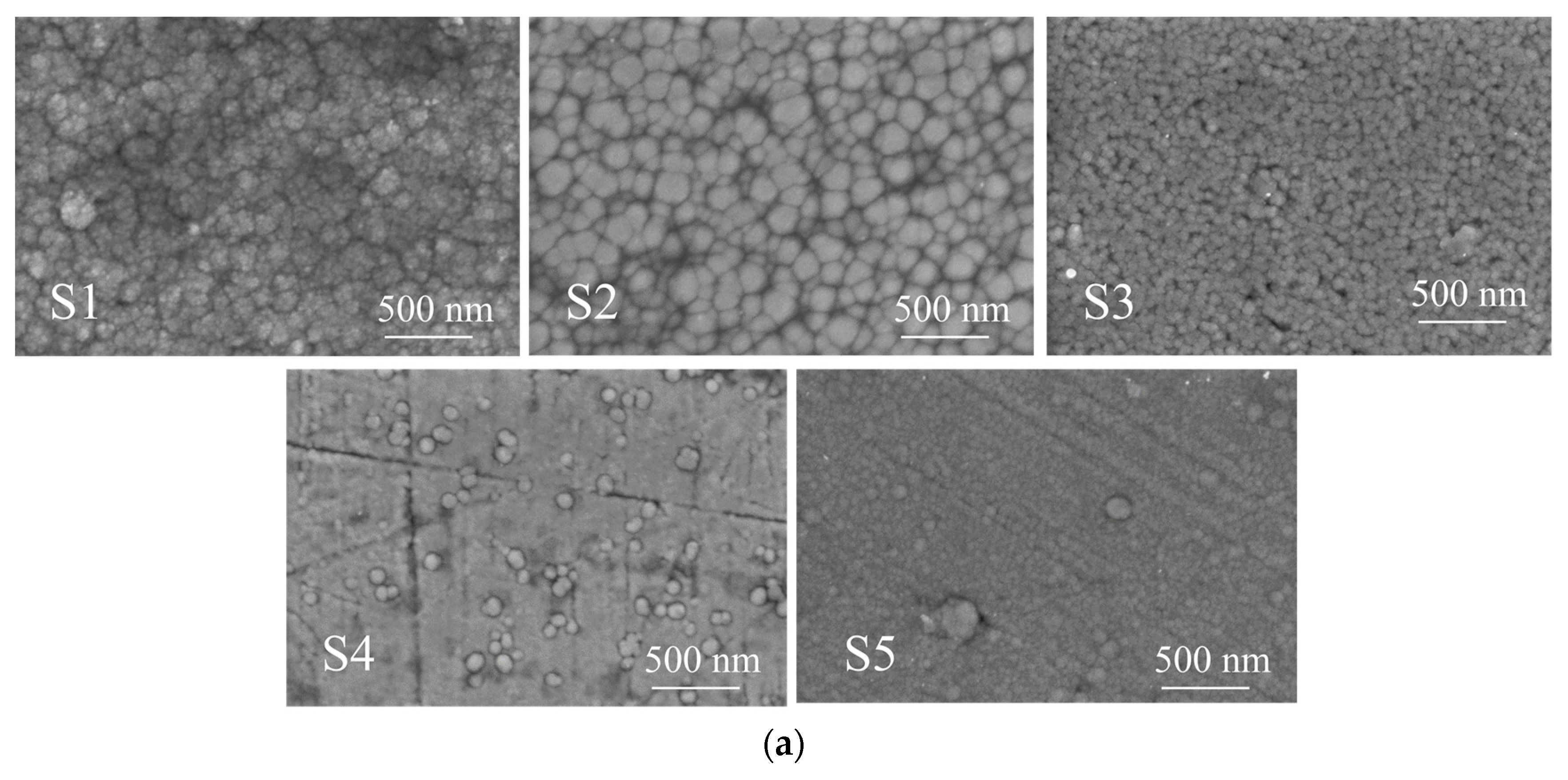
Figure 1. Surface and cross-sectional SEM images of (AlTiVCrNb)CxNy coating. (a) (AlTiVCrNb)CxNy coating surface morphology. (b) (AlTiVCrNb)CxNy coating surface morphology.
Lubricants 12 00325 g001aLubricants 12 00325 g001b
Figure 2. XRD and Raman spectra of coatings with different Zc values (AlTiVCrNb)CxNy. (a) XRD patterns. (b) Raman spectra.
Lubricants 12 00325 g002aLubricants 12 00325 g002b
Figure 3. The (AlTiVCrNb)CxNy coating XPS Nb 3d, Al2p, Cr2p, V2p, Ti2p, and C1s spectra. (a) Nb3d spectrum. (b) Al2p spectrum. (c) Cr2p spectrum. (d) V2p spectrum. (e) Ti2p spectrum. (f) C1s spectrum.
Lubricants 12 00325 g003aLubricants 12 00325 g003bLubricants 12 00325 g003c
Figure 4. The hardness H and elastic modulus E, H/E, and H3/E2 of (AlTiVCrNb)CxNy coatings with different Zc. (a) Hardness. (b) H/E and H3/E2.
Lubricants 12 00325 g004aLubricants 12 00325 g004b
Figure 5. The friction coefficient, the morphology of wear marks, and the distribution of oxygen elements in wear marks of coatings under different De values (AlTiVCrNb)CxNy. (a) The friction coefficient. (b) The wear scar appearance. (c) The distribution of oxygen element in wear scar.
Lubricants 12 00325 g005aLubricants 12 00325 g005b
Figure 6. SEM micrographs and EDS mapping images of the wear scars on the steel balls.
Lubricants 12 00325 g006
Figure 7. The Raman spectrum of the coated samples. (a) The Raman spectra of the wear tracks. (b) The Raman spectra of the wear scars on the steel balls.
Lubricants 12 00325 g007aLubricants 12 00325 g007b
Figure 8. The wear rate of (AlTiVCrNb)CxNy coating.
Lubricants 12 00325 g008
Table 1. The chemical composition of the target (at.%).
TargetAlCrNbTiVC
AlTiVCrNb19.419.720.720.319.9-
C-----99.9
Table 2. The deposition parameters of the coating.
SamplesGraphite Target Power
/(W)
Substrate Bias (Zc)/(V)AlTiVCrNb
Target Power/(W)
Roughness of
the Coating RZ/(µm)
Coating Thickness (nm)Cr Sputtering Target Power/(W)
S115001500.085 ± 0.0021176 ± 10100
S2150301500.083 ± 0.0021231 ± 10100
S3150601500.047 ± 0.0021259 ± 10100
S4150901500.029 ± 0.0021195 ± 10100
S51501201500.016 ± 0.0021162 ± 10100
Disclaimer/Publisher’s Note: The statements, opinions and data contained in all publications are solely those of the individual author(s) and contributor(s) and not of MDPI and/or the editor(s). MDPI and/or the editor(s) disclaim responsibility for any injury to people or property resulting from any ideas, methods, instructions or products referred to in the content.