Abstract
Amorphous carbon coatings are widely used due to their beneficial friction and wear characteristics. A detailed understanding of their behavior during running-in, apart from model tribosystems, has yet to be obtained. Multiple analytical methods were used to detect the physical and chemical changes in a ta-C coating and its thermally sprayed, metallic counterpart after a running-in procedure with pin-on-disk experiments. Both coatings exhibited changes in their surface and near-surface chemistry. The mechanisms in and on the metallic coating were identified to be a mixture of the third-body type, with the formation of gradients in the microstructure and chemistry and an additional carbon-rich tribofilm formation on top. The ta-C coating’s changes in chemistry with sp2 enrichment and lubricant element inclusions proved to be too complex to allocate them to tribofilm or third-body formation.
1. Introduction
Even though amorphous carbon coatings are already advanced (e.g., DuroGlide from Federal Mogul), the processes and mechanisms of the running-in are still largely not understood. Research has focused strongly on the mechanisms of model systems like diamond friction and wear behavior driven by amorphization and rehybridization to sp2 bonding [1]. Another important role is played by the surface passivation by hydroxyls under water lubrication, which inhibits cold welding and thereby reduces friction [2,3,4]. Furthermore, recent discoveries suggest similar mechanisms of passivation for glycerol-lubricated DLC–DLC contacts [5] and a strong dependency between the lubricant chemistry and wear beahvior of super hard ta-C coatings [6,7]. The wear of hard ta-C coatings on the asperity scale shows a similar mechanism to that of the amorphization of diamonds [8,9]. Further studies with advanced analytical methods into the wear mechanism of DLC lubricated with oleic acid indicated the formation of graphene oxides on the surface [10]. Closest to the applications outlined in this publication is those of a study focused on the interplay of ZDDP additives with hard DLC coatings and the formation of tribofilms using XPS and TEM [11].
This is astonishing, as this knowledge represents a major lever for the application and optimization of tribosystems. This article therefore deals with the running-in behavior of amorphous carbon coatings in a lubricated tribological system with a metallic counter body. It focuses on the tribochemical changes happening during running-in and tries to discuss the prevalent mechanisms with regard to the well-known third-body model from Godet and Berthier [12,13,14] and to the model of tribofilm formation on surfaces [15,16].
Tribological tests are often carried out with high loads and pressures in order to generate wear in a short time. Since the transferability of the results to practice is questionable, samples generated under realistic boundary conditions were analyzed in this work that were energetically similar to the real system, see [17]. Furthermore, no model systems were used; instead, materials and lubricants with industrial applications were considered. This work is expressly not intended as research related to combustion engine technology but as a fundamental contribution to the friction- and wear-reducing use of amorphous carbon coatings and thus to a general increase in the efficiency of industry.
2. Tribological Measurements and Physico-Chemical Analysis
2.1. Tribometry
The tribological results performed in this study were generated from a highly modified pin-on-disk tribometer (SST) from Tetra GmbH (Ilmenau, Germany). As the name suggests, the tribological system consisted of a rotating disk and an eccentrically mounted cylindrical pin. The disk was driven by a motor via a toothed belt at an angular speed , and the pin was positioned radially and vertically by two stepper motors. A normal force was applied by pretensioning a spring and, like the frictional force , was measured via a multiaxis force sensor from ME Meßsysteme using strain gauges. Contact was continuously supplied with oil heated to temperature via a circulating lubrication system. The oil circuit was designed for use with radionuclide technology, which is described more in detail in [18].
2.2. Topography Measurement
The topography of the samples used was recorded with a confocal white light interferometer (WLI) (Bruker ContourGT-K, Bruker Corp., Billerica, MA, USA). Two magnifications (10× and 50×) were used to measure the surface. The former was used to determine shape deviations, waviness, and line-based roughness parameters on an area of 5 × 5 mm2, and the latter was used to determine the surface-related roughness on an area of 100 × 100 μm2.
2.3. Determination of the Chemical Composition near the Surface
X-ray photoelectron spectrometry (XPS) was carried out using a PHI 5000 Versaprobe II (ULVAC-PHI, Chigasaki, Japan)). In combination with an argon ion beam, it was possible to measure the element concentrations with depth resolution by ablating the surface step by step and then recording the spectrum. The ablation rate was calibrated to 2 nm/min on a Si-SiO2 reference sample. For sputtering the DLC samples, the same procedure was used on a carbon coating on a silicon substrate reference sample provided by IWS. The removal of the 56 nm thick coating, which was measured in advance using X-ray reflectometry (XRR) at IWS, was carried out up to the SiC interface in 112 min. This corresponded to a removal rate of 0.5 nm/min. The lateral measuring range of the XPS was limited to a circle within a diameter of 200 μm. The photon energy of the Al-Kα X-ray source was 1486.7 eV, and the energy resolution was 0.2 eV.
2.4. Elastoplastic Material Characterization
A Hysitron Triboindenter TI 950 (Bruker Corp., Billerica, MA, USA) was used for elastoplastic material characterization. A cube corner was chosen as the tip, as this offered the smallest opening angle and tip radius with a self-similar tip shape [19]. The indenter and its tip were used as an AFM to image the surfaces of the sample and to position the tip. The loading function for the quasistatic indents went up to 1 with a constant strain rate and subsequent hold time to correct for creep. The area function of the tip is necessary for converting the measured forces and displacements into stresses and strains and then into modulus of elasticity and hardness. This requires the indentation area as a function of the indentation depth. The standard method for this is the Oliver–Pharr method on a test specimen with known and constant properties (usually quartz glass) [20]. A finer determination of the area function is possible by means of self-imaging of the tip, as shown by Saringer et al. [21]. For this purpose, a TGT1-AFM reference grating, which consisted of sharp needles and thus enabled in situ imaging of the tip, was scanned. The cross-sectional area was then calculated from the actual shape depending on the indentation depth [21].
2.5. Determination of Carbon Hybridization
Electron energy loss spectroscopy (EELS) makes use of the inelastic interaction of an electron beam with the electrons in a sufficiently thin sample [22]. Inelastic scattering can have several causes and accordingly occurs with different energy losses in the spectrum. In the low-loss range, for example, these are plasmons, while at higher loss energies, the electrons of the inner shells are excited and lead to a clearly detectable ionization edge [23]. EELS is one of the oldest methods of DLC analysis and is based on the evaluation of the carbon K-edge [24]. Here, the sp2 content is determined via the intensity ratio of the and states [25]. By considering the plasmon losses, relative changes in sample thickness are corrected [26,27]. Due to the TEM preparation, no exact sp2 content of DLC coatings can be determined using EELS, as this is systematically overestimated [25,27]. Nevertheless, a semiquantitative statement and precise determination of sp2 gradients in carbon-based materials is possible due to the high lateral resolution. An FEI Titan TEM (Thermo Fisher Scientific, Waltham, MA, USA) equipped with a Gatan Imaging Energy Filter Tridiem model 865 HR was used for the EELS measurements. The titanium microscope was operated at 300 kV in STEM mode to minimize radiation damage.
2.6. Nanostructural Investigation
Transmission electron microscopy (TEM) and high-resolution TEM (HRTEM) are powerful tools for investigating changes due to tribological loading [28]. In this work, both were used to observe the DLC near-surface volume, as a higher resolution and a much higher contrast than in an FIB cross-section in SEM are possible. The preparation of the lamellae was carried out with Ga+-FIB, as the damage induced in the DLC caused by Ga+ is well documented in the literature [29,30]. The fast Fourier transform (FFT) of HRTEM images enables an analysis of the near and far order, respectively, to separate them and thus make crystal orientations recognizable [25,31].
2.7. Chemical and Physical Analysis
Raman spectroscopy is a nondestructive method for the chemical and physical analyses of materials. It is widely used in the characterization of (amorphous) carbon coatings. This measuring method is based on the eponymous Raman effect, in which light is inelastically scattered by molecules. This energy transfer can be quantified using the wavelength shift of the scattered light. In the case of carbon, the D maximum at 1350 cm−1 and the G maximum at (1580–1600) cm−1 were used. These two modes are mainly influenced by the order of the sp2-hybridized regions. A derivation of the sp3 content of amorphous carbon is only possible indirectly [32]. For this purpose, their intensity ratio and the position of the G peak are used:
In this study, the intensity ratio was calculated from the ratio of the heights of the individual maxima. For this purpose, the measured Raman spectrum in the relevant range was approximated with the sum of a Cauchy–Lorentz distribution for the D peak and a Breit–Wigner–Fano line for the G peak using the least squares method [32]. The background resulting from the fluorescence of the sample was removed via polynomial regression. An inVia confocal microscope (Renishaw, Wotton-under-Edge, UK) with a laser wavelength of 532 nm and 20 and 100× optical magnification was used. This resulted in a minimum lateral resolution of 1 μm, with the theoretical value based on a numerical aperture (NA) of 0.9 and the Rayleigh criterion being 361 nm. As Raman spectroscopy is not surface-sensitive, it was only used to characterize the carbon on the metallic counterpart. The surface was mapped using a grid and classified according to the occurrence of the characteristic carbon maxima.
3. Materials of the Tribosystem
3.1. Iron Spray Coating
Iron spray coating is a standard material for cylinder liners. This coating is applied to aluminum crankcases in a series production process using arc wire spraying (TWA) of two 13Mn6 wires [33].
The material for the tribometer tests was taken directly from an unhoned cylinder liner. The separated strips were ground plane-parallel, and the 5 mm pins were created from them using water jet cutting. Finishing was carried out in a cup grinding machine via a process similar to honing. This meant that both the coating thickness and the roughness were based on the honed cylinder bore. The Abbot parameters averaged over all samples were Svk 819 ± 160, Sk 656 ± 236, and Spk (232 ± 49) nm. The edges of all pins were rounded off manually due to possible burrs, which is why the actual diameter was 4.95 mm. Subsequently, all pins were measured in the WLI, and samples with burrs in general, as well as with waviness and shape deviations greater than 1 μm, were excluded in order to enable reproducible, full-surface contact in the tribometer.
3.2. DLC
Coatings with different sp3 contents were deposited onto ground 100Cr6 disks using a PVD vacuum process at the Fraunhofer IWS. The so-called LaserArc process, in which a laser scans the graphite cathode and vaporizes the carbon, was used. A detailed description of the coating procedure, including substrate preparation and machine parameters, can be found in [34]. The plasma was filtered to reduce the particle implantation and thus the defect density [35]. Despite filtering, the coatings exhibited a large number of growth defects, especially within the investigated coating thickness range of (5.1–6.3) μm, measured in a calotte cut by IWS. These defects in turn led to the formation of a rough surface dominated by spikes (firmly anchored) and droplets (weakly bonded). These surfaces were not suitable for tribological use, which is why they had to be smoothed [36]. Two different methods were used for this purpose. One was short-stroke honing using a diamond belt, and the other was brush smoothing. The first method is also known as "superfinishing" and uses high-frequency oscillation perpendicular to the feed direction of the belt and while rotating. The resulting surface roughness is displayed in Table 1. This article focused on a ta-C coating with a Young’s modulus of 523 GPa, a hardness of 50 GPa, and an sp3 content of 66%.

Table 1.
Abbot–Firestone roughness values for the tested DLC coatings. Index a denotes coatings in as-deposited state, g for ground state, and b brushed smoothed state.
3.3. Lubricant
All experiments in this work were carried out with the same lubricant at an identical temperature (80 °C). This was a fully additive engine oil of SAE viscosity class 0W20 from Fuchs Petrolub. On the one hand, this oil contained zinc dialkyl dithiophosphate (ZnDTP), which is a common additive for wear protection [16,37]. On the other hand, molybdenum dithiocarbamate (MoDTC) was used as a typical friction modifier [38]. The elemental composition of the oil was analyzed by ICP-OES.
4. Results and Discussion on the Differentiation between Third Body and Tribofilm
Based on the mechanisms of third body formation in metal-metal tribosystems, we discussed whether DLC is subject to a comparable change in the running-in or whether the tribochemical change is limited to a film structure. The behavior of the mating body was also considered in the discussion, as part of the film or third body also remains on the mating body when the contact is separated.
4.1. Tribometry
All coatings were tested in the same manner, which means that at least three experiments were conducted. The procedure included a preliminary test in which a parameter field dictated by the Stribeck curve was defined. Starting with low contact pressure and high velocity, followed by a decrease in velocity moving from hydrodynamic lubrication to boundary lubrication, the load was increased until the maximum load of the pin-on-disk-tribometer of 980 N was reached or the simultaneously measured wear rate went beyond 2 μm/h. From the initial experiment, so-called key stress levels were defined, which were in turn used for the parameterization in a new experiment. The procedure itself as well as the resulting coefficients of friction and wear rates are displayed and discussed in detail in [17].
The results of the tribometrical testing of the differently smoothed ta-C coatings are shown via Stribeck curves after running-in in Figure 1. To facilitate the comparison, all CoFs are shown independent of the pseudo calculated from the Hersey parameter and the resulting combined roughness Sq in the following manner:
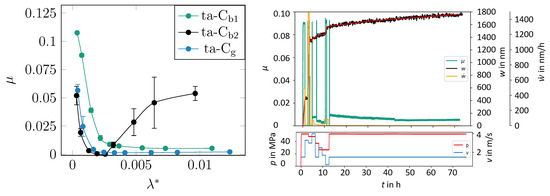
Figure 1.
Stribeck curves acquired after running-in with coefficient of friction over pseudo (left) and the running-in of the ta-Cg coating with CoF in green, measured wear from the pin in black, and calculated wear rates in yellow (right).
By doing so, the differences in the resulting roughness of the coatings and their counterbody were omitted from the comparison of friction coefficients under mixed lubrication. To give the reader an idea as to what happens during running-in, the results of the testing of the ground ta-C coating, which had the lowest CoFs in the Stribeck curve, are displayed in Figure 1 on the right. The test parameters were chosen in the same way as in the previously cited publication, with an initial contact pressure of 52 MPa and a relative velocity 1 m/s. Initial friction was high (CoF 0.9) and so were the linearized wear rates, which reached values of up to 1.5 μm/h. Passing the key stress levels, the CoF decreased below 0.01 after around twelve hours of stressing, and the pin wear rate stabilized below 10 nm/h.
All following investigations were carried out on specimens from the presented pin-on-disk experiment for a concise and focused discussion.
4.2. Gradient Formation
For the 13Mn6 spray coating, the formation of a gradient in the microstructure below the surface and its correlation with the wear rates were detected and are shown in Figure 2 on the left and are compared to those of the pristine material (right). The FIB cross-sections were placed in parallel to both the grooves and on top inside a ridge line.

Figure 2.
Near-edge microstructure of the spray coating after running-in against ta-C on the (left) and for comparison from an unworn, ground specimen on the (right).
The characteristics of near-surface microstructure are described in the literature [15,28]. A gradient formed in the grains from the microcrystalline structure above the bulk grains (between the lower and middle area, horizontal line) to the nanocrystalline near-surface region (above the upper line). This is in good agreement with the spray coatings that were rubbed against a metallic counter body [39], grey cast iron against chromium plated pins [40], and for steel–steel pairings under similar conditions [41]. This below-surface structure does not always develop in the same way but is influenced by the hardness of the DLC and its final processing with regard to grain size and the extent of the gradient.
The XP spectra and depth profiles (shown in Figure 3) were used to detect additive components from the wear protection (zinc and phosphorus) and the friction modifier (molybdenum and sulphur), which were present below the surface in decreasing concentrations. This form of gradient suggests the formation of a third body of natural and artificial material flow rather than an adsorbed film.
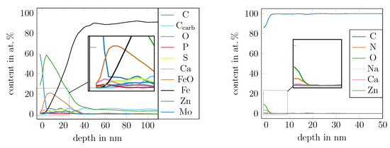
Figure 3.
XPS depth profiles from a 13Mn6-coated pin (left) after running-in against a ta-C coating (right).
The search for gradients in amorphous carbon coatings was more difficult, as the tribochemically altered near-edge volume was a maximum of 100 in thickness. For the ta-C coating, the XPS indicated a tribochemical interaction only up to a depth of 20 . However, the gradients in XPS depth profiles are only of limited significance for two reasons. Firstly, they are superimposed by the sp3-rich CHx contamination of the surface. Secondly, the information depth of the C1s photoelectron is just under ten nanometers. However, this is not in the form of a uniform distribution but of a logarithmic decrease in the exit probability with increasing depth [42]. Ten nanometers represents a limit with the 99% information quantity, corresponding to 3 of a normal distribution. As such, a thin film (20 ) cannot be separated from a gradient at all with XPS and C1s evaluation.
The results of the nanoindentation, plotted as Young’s modulus over height (ergo sample topography) in Figure 4a, must also be viewed critically, as the tip of the nanoindenter measures the elastic interaction with the material underneath and around the indentation surface, even at the smallest indentation depths. This means that the elastic modulus measured there, which is linearly related to the sp3 content, is not suitable for determining the shape of a tribochemically modified volume, especially as the average value of (347 ± 17) GPa inside the wear track is not significantly different from the values outside ((340 ± 14) GPa) of it. The only difference can be found in the slopes of the linear regression for both datasets, which indicate a lower Young’s modulus on high points inside the wear track.
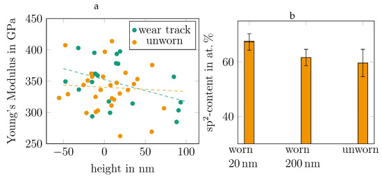
Figure 4.
Comparison of the Young’s moduli over measured topography height acquired on an unworn area on a ta-C disk in orange and data from inside the wear track in green (a) and EELS-measured sp2 contents on two lamellae prepared from the wear track with windowing in two different depths and from an unworn area on the same DLC disk (b).
Although the results of the investigation using EELS in Figure 4b shows significant differences in the sp2 content of the ta-C coating, in good agreement with the XPS, it is not possible to make a statement about the gradients due to the windowing that occurred when the lamella was scanned. Only the observations of the near-surface area using HRTEM and bright-field TEM in Figure 5 provide information about its composition. The original specimen surface is marked in both pictures with a white dashed line. Both lamellae show platinum contamination to some extent, even though the lamella from the worn ta-C sample was sputter-coated with gold beforehand. The lighter areas below the surface are sharp-edged (indicated with black dashed line) in the manner of a film. At first glance, this appears to be an argument in favor of the structure of a tribofilm.
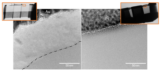
Figure 5.
HRTEM image of the ta-C lamellae from under the surface of the wear track on the (left) and from an unworn area on the (right). The original surface is marked with a white dashed line.
In detail, however, there are inconsistencies with this model. With the surface showing traces of plastic flow in the SEM image and the presence of a metallic calcium phase (a Ca-L-edge was detected at 345 eV via EELS) below the surface, marked with the black dashed line in the HRTEM image in Figure 6, it could be assumed that the near-surface zone formed by mechanical mixing in frictional contact and thus was analogous to the formation of a third body. Salinas Ruiz et al. came to a similar conclusion. They used HRTEM and EDX to demonstrate the formation of a third body by incorporating the wear particles of the ta-C coating and lubricant components, in particular sulphur and zinc [11]. A tribofilm would form on the surface in the form of an adsorbent and would not allow the incorporation of material under the surface. The formation of a tribofilm in the form of graphene oxide, as demonstrated by Barros Bouchet et al. in [10], could not be demonstrated, as the ta-C coating was amorphous up to the surface.
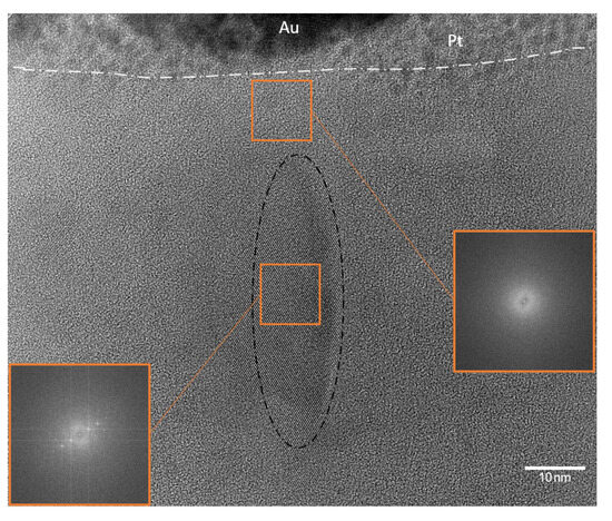
Figure 6.
Magnified acquisition of Figure 5 left, directly beneath the surface, with the FFT of an amorphous area on the right and of an area with a long distance order (marked with the black dashed line) on the lower left.
4.3. Material Transfer
A third body comprises the material flows from the first two bodies. Since the third body remains on the two first bodies when the contact is released, material transferred from the other first body should be present on their surface. On the 13Mn6 spray coat, the detection of carbon transfer was not trivial, as this had to be separated from the lubricant residues in the form of CHx contamination. The XPS shows a depth of approximately 5 nm in all depth profiles, which was dominated by sp3-hybridized carbon. Below this, there was generally a gradient in the carbon content. The results of Raman spectroscopy in Figure 7 show a film-like distribution of carbon, with local variations in the D- and G-peak intensity ratio and correlated G shift.
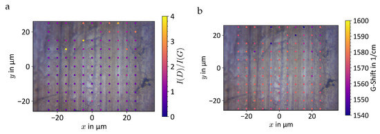
Figure 7.
Raman mapping of a 13Mn6 pin after running-in against ta-C with intensity ratio (a) and G shift (b). Values outside the limits were excluded.
The average value is 0.97 ± 0.05, with an average G shift of (1572 ± 1) cm−1. The local variation in both values increased to an intensity ratio of 3.9 and a G shift of 1540 cm−1. The average values indicated that the carbon film was between nanocrystalline graphite and a-C with an sp2 content of 90%, according to [43]. The deviating spots should be treated with caution, since the deviations did not align with the visible geometry (patches, holes, and grooves) even though the marker size in the scatter plot was scaled according to the approximate laser spot diameter based on the airy disk calculated from the wavelength and NA. Additionally, the values measured at those spots with low G shifts and high values do not match the data points from Ferrari and Robertson (neither for amorphous carbon nor for hydrocarbons) [32,43].
On the DLC side, it was much easier to prove a transfer from the 13Mn6 spray coating by measurement. As this coating consisted largely of iron, it should be possible to detect iron on or in the DLC, be it in the form of oxides, carbides, or metallic iron. As all XPS measurements showed, no transfer of iron in any form could be detected. This is therefore a contradiction to the model concept of the third body, as this should consist of both internal material inflows as a natural third body.
5. Conclusions
In summary, it can be stated that tribochemical changes in near-surface volume cannot simply be attributed to the phenomenon of the formation of a third body or the formation of a tribofilm. For the metal side, there is evidence in the material that gradients develop in the microstructure and in the chemistry, as is typical for third bodies in metallic tribosystems. Furthermore, XPS, SEM, and Raman show that an additional carbonaceous tribofilm builds up. The amorphous carbon coatings appear to participate only to a limited extent in the formation of a third body. There is no transfer from the metallic counter body. However, there is the incorporation of foreign material, plastic flow, and rehybridization of the carbon. Thus, the tribological behavior of DLC–metal systems can neither be clearly assigned to the path of run-in via the formation of a third body nor to the formation of a transfer film.
A further investigation of the near-surface volume in the DLC requires in-depth measurements. The resolution of the possible sp2–sp3 gradient requires a smaller windowing in the EELS measurement, which will, however, be accompanied by greater measurement uncertainty. Furthermore, a qualification of the distribution of the tribochemical modification using EDX on the same TEM lamella would be desirable.
Gaining a deeper understanding of tribofilm formation on iron spray coating requires a similar approach. A three-dimensional mapping of the carbon hybridization state could be acquired using Auger electron spectroscopy coupled with a sputter etching technique that does not alter carbon bonding, like argon gas cluster ions.
Author Contributions
Conceptualization, M.S.; formal analysis, J.F.; funding acquisition, M.S.; investigation, J.F.; methodology, J.F.; project administration, J.F.; writing—original draft, J.F. and M.S. All authors have read and agreed to the published version of this manuscript.
Funding
This research was funded by Bundesministerium für Wirtschaft und Klimaschutz grant number 03ET1609.
Data Availability Statement
Dataset available on request from the authors.
Acknowledgments
The authors would like to thank Frank Kaulfuß and Stefan Makowski (Fraunhofer IWS, Dresden) for providing the DLC coatings. From Fraunhofer IWM, we thank Philipp Daum and Dominic Linsler for XPS and SEM. Erich Müller and Reinhard Schneider from the Laboratory for Electron Microscopy (LEM KIT, Karlsruhe) are thanked for the TEM preparation and EELS measurements.
Conflicts of Interest
The authors declare no conflicts of interest.
References
- Pastewka, L.; Moser, S.; Gumbsch, P.; Moseler, M. Anisotropic mechanical amorphization drives wear in diamond. Nat. Mater. 2011, 10, 34–38. [Google Scholar] [CrossRef] [PubMed]
- Tzeng, Y. Very low friction for diamond sliding on diamond in water. Appl. Phys. Lett. 1993, 63, 3586–3588. [Google Scholar] [CrossRef]
- Zilibotti, G.; Corni, S.; Righi, M.C. Load-Induced Confinement Activates Diamond Lubrication by Water. Phys. Rev. Lett. 2013, 111, 146101. [Google Scholar] [CrossRef] [PubMed]
- Kim, J.E.; Choi, J.I.J.; Kim, J.; Mun, B.S.; Kim, K.J.; Park, J.Y. In-Situ Nanotribological Properties of Ultrananocrystalline Diamond Films Investigated with Ambient Pressure Atomic Force Microscopy. J. Phys. Chem. C 2021, 125, 6909–6915. [Google Scholar] [CrossRef]
- Kuwahara, T.; Romero, P.A.; Makowski, S.; Weihnacht, V.; Moras, G.; Moseler, M. Mechano-chemical decomposition of organic friction modifiers with multiple reactive centres induces superlubricity of ta-C. Nat. Commun. 2019, 10, 151. [Google Scholar] [CrossRef]
- Makowski, S.; Weihnacht, V.; Schaller, F.; Leson, A. Ultra-low friction of biodiesel lubricated ta-C coatings. Tribol. Int. 2014, 71, 120–124. [Google Scholar] [CrossRef]
- Makowski, S.; Schaller, F.; Weihnacht, V.; Englberger, G.; Becker, M. Tribochemical induced wear and ultra-low friction of superhard ta-C coatings. Wear 2017, 392-393, 139–151. [Google Scholar] [CrossRef]
- Kunze, T.; Posselt, M.; Gemming, S.; Seifert, G.; Konicek, A.R.; Carpick, R.W.; Pastewka, L.; Moseler, M. Wear, Plasticity, and Rehybridization in Tetrahedral Amorphous Carbon. Tribol. Lett. 2014, 53, 119–126. [Google Scholar] [CrossRef]
- von Lautz, J.; Pastewka, L.; Gumbsch, P.; Moseler, M. Molecular Dynamic Simulation of Collision-Induced Third-Body Formation in Hydrogen-Free Diamond-Like Carbon Asperities. Tribol. Lett. 2016, 63, 26. [Google Scholar] [CrossRef] [PubMed]
- de Barros Bouchet, M.I.; Martin, J.M.; Avila, J.; Kano, M.; Yoshida, K.; Tsuruda, T.; Bai, S.; Higuchi, Y.; Ozawa, N.; Kubo, M.; et al. Diamond-like carbon coating under oleic acid lubrication: Evidence for graphene oxide formation in superlow friction. Sci. Rep. 2017, 7, 46394. [Google Scholar] [CrossRef]
- Salinas Ruiz, V.R.; Kuwahara, T.; Galipaud, J.; Masenelli-Varlot, K.; Hassine, M.B.; Héau, C.; Stoll, M.; Mayrhofer, L.; Moras, G.; Martin, J.M.; et al. Interplay of mechanics and chemistry governs wear of diamond-like carbon coatings interacting with ZDDP-additivated lubricants. Nat. Commun. 2021, 12, 4550. [Google Scholar] [CrossRef] [PubMed]
- Godet, M. The third-body approach: A mechanical view of wear. Wear 1984, 100, 437–452. [Google Scholar] [CrossRef]
- Berthier, Y. Third-Body Reality—Consequences and Use of the Third-Body Concept to Solve Friction and Wear Problems. In Wear—Materials, Mechanisms and Practice; John Wiley & Sons Ltd.: Hoboken, NJ, USA, 2005; pp. 291–316. [Google Scholar] [CrossRef]
- Fillot, N.; Iordanoff, I.; Berthier, Y. Wear modeling and the third body concept. Wear 2007, 262, 949–957. [Google Scholar] [CrossRef]
- Scherge, M.; Brink, A.; Linsler, D. Tribofilms Forming in Oil-Lubricated Contacts. Lubricants 2016, 4, 27. [Google Scholar] [CrossRef]
- Spikes, H. The History and Mechanisms of ZDDP. Tribol. Lett. 2004, 17, 469–489. [Google Scholar] [CrossRef]
- Faller, J.; Scherge, M. The Identification of an Adequate Stressing Level to Find the Proper Running-In Conditions of a Lubricated DLC-Metal-System. Lubricants 2020, 8, 88. [Google Scholar] [CrossRef]
- Scherge, M.; Pöhlmann, K.; Gervé, A. Wear measurement using radionuclide-technique (RNT). Wear 2003, 254, 801–817. [Google Scholar] [CrossRef]
- Hintsala, E.D.; Hangen, U.; Stauffer, D.D. High-Throughput Nanoindentation for Statistical and Spatial Property Determination. JOM 2018, 70, 494–503. [Google Scholar] [CrossRef]
- Oliver, W.C.; Pharr, G.M. Measurement of hardness and elastic modulus by instrumented indentation: Advances in understanding and refinements to methodology. J. Mater. Res. 2004, 19, 3–20. [Google Scholar] [CrossRef]
- Saringer, C.; Tkadletz, M.; Kratzer, M.; Cordill, M.J. Direct determination of the area function for nanoindentation experiments. J. Mater. Res. 2021, 36, 2154–2165. [Google Scholar] [CrossRef]
- Fink, J. Recent Developments in Energy-Loss Spectroscopy. Adv. Electron. Electron Phys. 1989, 75, 121–232. [Google Scholar] [CrossRef]
- Egerton, R.F. Electron energy-loss spectroscopy in the TEM. Rep. Prog. Phys. 2008, 72, 016502. [Google Scholar] [CrossRef]
- Berger, S.D.; McKenzie, D.R.; Martin, P.J. EELS analysis of vacuum arc-deposited diamond-like films. Philos. Mag. Lett. 1988, 57, 285–290. [Google Scholar] [CrossRef]
- Zhang, X.; Schneider, R.; Müller, E.; Gerthsen, D. Practical aspects of the quantification of sp2-hybridized carbon atoms in diamond-like carbon by electron energy loss spectroscopy. Carbon 2016, 102, 198–207. [Google Scholar] [CrossRef]
- Oh-ishi, K.; Ohsuna, T. Inelastic mean free path measurement by STEM-EELS technique using needle-shaped specimen. Ultramicroscopy 2020, 212, 112955. [Google Scholar] [CrossRef]
- Mangolini, F.; Li, Z.; Marcus, M.A.; Schneider, R.; Dienwiebel, M. Quantification of the carbon bonding state in amorphous carbon materials: A comparison between EELS and NEXAFS measurements. Carbon 2021, 173, 557–564. [Google Scholar] [CrossRef]
- Fischer, A.; Dudzinski, W.; Gleising, B.; Stemmer, P. Analyzing Mild- and Ultra-Mild Sliding Wear of Metallic Materials by Transmission Electron Microscopy. In Microtechnology and MEMS; Springer International Publishing: Berlin/Heidelberg, Germany, 2018; pp. 29–59. [Google Scholar] [CrossRef]
- Mayer, J.; Giannuzzi, L.A.; Kamino, T.; Michael, J. TEM Sample Preparation and FIB-Induced Damage. MRS Bull. 2007, 32, 400–407. [Google Scholar] [CrossRef]
- Tong, Z.; Jiang, X.; Luo, X.; Bai, Q.; Xu, Z.; Blunt, L.; Liang, Y. Review on FIB-Induced Damage in Diamond Materials. Curr. Nanosci. 2016, 12, 685–695. [Google Scholar] [CrossRef]
- Chen, X.; Zhang, C.; Kato, T.; Yang, X.A.; Wu, S.; Wang, R.; Nosaka, M.; Luo, J. Evolution of tribo-induced interfacial nanostructures governing superlubricity in a-C:H and a-C:H:Si films. Nat. Commun. 2017, 8, 1675. [Google Scholar] [CrossRef]
- Ferrari, A.C.; Robertson, J. Resonant Raman spectroscopy of disordered, amorphous, and diamondlike carbon. Phys. Rev. B 2001, 64, 075414. [Google Scholar] [CrossRef]
- Biberger, J. Tribologisch Induzierte Oberflächenveränderung im Reib-Verschleiß-Kontakt Kolbenring Gegen Zylinderlaufbahn. Ph.D.Thesis, TU Berlin, Berlin, Germany, 2017. [Google Scholar] [CrossRef]
- Kaulfuss, F.; Weihnacht, V.; Zawischa, M.; Lorenz, L.; Makowski, S.; Hofmann, F.; Leson, A. Effect of Energy and Temperature on Tetrahedral Amorphous Carbon Coatings Deposited by Filtered Laser-Arc. Materials 2021, 14, 2176. [Google Scholar] [CrossRef]
- Schultrich, B. Structure and Characterization of Vacuum Arc Deposited Carbon Films—A Critical Overview. Coatings 2022, 12, 109. [Google Scholar] [CrossRef]
- Schultrich, B. Tetrahedrally Bonded Amorphous Carbon Films I; Springer: Berlin/Heidelberg, Germany, 2018. [Google Scholar]
- Mosey, N.J.; Muüser, M.H.; Woo, T.K. Molecular Mechanisms for the Functionality of Lubricant Additives. Science 2005, 307, 1612–1615. [Google Scholar] [CrossRef] [PubMed]
- Vengudusamy, B.; Green, J.H.; Lamb, G.D.; Spikes, H.A. Behaviour of MoDTC in DLC/DLC and DLC/steel contacts. Tribol. Int. 2012, 54, 68–76. [Google Scholar] [CrossRef]
- Linsler, D.; Kümmel, D.; Nold, E.; Dienwiebel, M. Analysis of the running-in of thermal spray coatings by time-dependent stribeck maps. Wear 2017, 376–377, 1467–1474. [Google Scholar] [CrossRef][Green Version]
- Shakhvorostov, D.; Gleising, B.; Büscher, R.; Dudzinski, W.; Fischer, A.; Scherge, M. Microstructure of tribologically induced nanolayers produced at ultra-low wear rates. Wear 2007, 263, 1259–1265. [Google Scholar] [CrossRef]
- Brink, A.; Lichtenberg, K.; Scherge, M. The influence of the initial near-surface microstructure and imposed stress level on the running-in characteristics of lubricated steel contacts. Wear 2016, 360–361, 114–120. [Google Scholar] [CrossRef]
- Jablonski, A.; Powell, C.J. Practical expressions for the mean escape depth, the information depth, and the effective attenuation length in Auger-electron spectroscopy and x-ray photoelectron spectroscopy. J. Vac. Sci. Technol. Vacuum, Surfaces, Film. 2009, 27, 253–261. [Google Scholar] [CrossRef]
- Ferrari, A.C.; Robertson, J. Interpretation of Raman spectra of disordered and amorphous carbon. Phys. Rev. B 2000, 61, 14095–14107. [Google Scholar] [CrossRef]
Disclaimer/Publisher’s Note: The statements, opinions and data contained in all publications are solely those of the individual author(s) and contributor(s) and not of MDPI and/or the editor(s). MDPI and/or the editor(s) disclaim responsibility for any injury to people or property resulting from any ideas, methods, instructions or products referred to in the content. |
© 2024 by the authors. Licensee MDPI, Basel, Switzerland. This article is an open access article distributed under the terms and conditions of the Creative Commons Attribution (CC BY) license (https://creativecommons.org/licenses/by/4.0/).