1. Introduction
Wet disk clutches are widely used in automotive, industrial, heavy-duty, marine, and other applications. The requirements and operating conditions associated with these clutches can vary significantly from application to application, resulting in different design objectives. However, the frictional behavior of these machine elements is critical to the safe and reliable operation of the system and influences the shifting comfort and NVH of the drivetrain.
The frictional behavior of wet disk clutches is subject to many influences and their complex interactions. So far, it cannot be reliably simulated. Therefore, appropriate experimental tests are required to evaluate the functional behavior. Component test rigs guarantee the transferability of the results to real systems by using genuine clutches and application-relevant operating conditions. These test rigs allow for the investigation of influences on the choice of components, such as friction lining, steel disk, and lubricant, but also of the operating conditions, such as mechanical and thermal loads, initial damage, and the clutch design, on the friction behavior.
In general, the friction behavior is dominated by the boundary lubrication film mainly created by oil additives at the contact of the highly porous friction materials’ and the steel disk’s surfaces [
1]. In this context, friction-modifying additives are known to be crucial in protecting the drivetrain from unwanted shudder due to their ability to lower the coefficient of friction (
CoF; in tribology also
µ or
f) at low sliding velocities and to cause an approximately logarithmic increase in the
CoF over sliding velocity [
1,
2,
3,
4]. Shudder is a self-excited oscillation of the clutch that typically occurs when the slope of the
CoF over the sliding velocity
vs is negative [
5] and is based on the physics of stick–slip friction. The occurrence of shudder is critical due to vibrations that occur. Detailed investigations by Ingram et al. [
1,
6] on the influence of various additives on friction behavior with pin-on-disk tests confirm the high importance of the composition of the lubricant on functional behavior. In addition to the influence of the lubricant, the general type of friction material (e.g., [
7]), its surface topography (e.g., [
8]), or its mechanical properties (e.g., permeability [
9,
10] and Young’s modulus [
11]) can have a decisive influence on the frictional behavior. Studies also determine the influence of the steel plate’s surface finishing on friction (e.g., [
12,
13,
14]).
However, the design of modern friction systems is concerned with preventing shudder and the ability to transmit high torque without slip. This is especially interesting for safety or torque-limiting clutches. Here, the lowering influence of the friction modifier additives on the
CoF at low sliding velocities is critical for a good torque-transmitting capacity. In this context, the transition from static to dynamic friction is hard to identify because creep phenomena can occur below the known macroscopic static friction coefficient (
SFC) [
15]. Investigations confirm that the occurrence of slip at very low sliding velocities is caused by the tribological boundary layer (e.g., [
4]). This makes a distinguished investigation of the transition from static to dynamic friction necessary. Early investigations on this transition are mentioned by Herscovici [
16], describing a specialized test rig for this purpose. Other approaches characterize the static friction by the
CoF at a specific differential speed (here: ∆
n = 2 rpm) [
17] or at the end of brake shift operation [
18]. Lloyd et al. [
19] confirm differences between the determination of the “static” friction behavior using three different measurement methods. In this context, the
CoF is consecutively determined at the end of a brake shift, at the breakaway at the initiation of forced slip, and during the following forced steady-state slip. In conclusion, all of these approaches show high sensitivity of the measurement of the friction behavior at the transition from static to dynamic friction. This leads to the necessity of an optimized test method for this operational mode. In this context, the development of a test rig guaranteeing optimized circumstances for determining the friction behavior at the transition of static to dynamic friction behavior [
7] is an essential part of the methodology presented in this paper.
Nevertheless, numerous publications focus on the investigation of dynamic friction behavior, which can be characterized in different, application-oriented operational modes like brake shift operation (e.g., [
20]), steady slip (e.g., [
21]), or transient slip (e.g., [
22]). The choice of a suitable test procedure should follow the needs of the intended operation mode for the genuine clutch system.
This paper focuses on the application-oriented testing of wet disk clutches, considering the strong influence of sliding velocity on friction behavior using a holistic approach. This approach allows for the measurement of friction behavior in a wide range of sliding velocities and, therefore, is adaptable to multiple applications, from, e.g., industrial to marine, heavy-duty, and automotive clutches. The results extend the findings of Meingassner [
7] and describe the applicability of the methodology proposed. Previous insights with paper-based and sinter-metallic friction lining can be confirmed for carbon friction materials used in limited-slip differentials. All investigations confirm values of the
CoF in micro-slip operation far below those in operational modes with higher sliding velocities. This underlines the need for a holistic investigation of friction behavior. The methodology applies to the operational conditions the clutch is exposed to in real applications and supports a sound understanding of the clutch’s friction behavior. The principles of the methodology are based on Meingassner [
7]. Since then, it has been applied to different friction systems and adapted to the needs of various research objectives, such as the influence of the steel plate on the friction behavior of automotive friction systems [
23]. This paper offers novel insights into the procedure for determining holistic friction behavior by using temperature measurements inside the clutch and comparing the results of friction systems from different applications. In addition to previous investigations, the combination of different operational modes suitable for each application is proposed.
2. Materials and Methods
The experiments are based on measurements of two optimized wet clutch component test rigs (KLP-260 and LK-3, both from FZG, Munich, Germany). Both test rigs operate in brake mode with a fixed outer carrier. Test rig KLP-260 allows for the measurement of the friction behavior at low, moderate, and high differential speeds. In contrast, test rig LK-3 enables measuring friction behavior at low speeds (micro-slip) and static friction. These measurements allow for the evaluation of the slope of the CoF over sliding velocity vs.
2.1. Measurement of the Dynamic Friction Behavior
The component test rig KLP-260 allows for measuring the dynamic friction behavior in multiple two operational modes.
In shifting operation, flywheels are accelerated by the main drive (speed-controlled electric motor connected to the shaft via a belt drive) up to a maximum speed. The main drive is decoupled before the investigated clutch or brake is actuated, leading to brake shift operation. In this case, only the starting differential speed is set, and the following shifting process depends on the actuation, the inertia of the flywheels (1 kg∙m
2 (connectable by actuator) and additionally 0.1 … 0.75 kg∙m
2 (manually connectable)), and the underlying torque transmission or friction behavior of the system. In forced slip operation, the differential speed of the closed clutch is directly controlled by the creep drive (speed-controlled electric motor with gearbox), which is connected to the inner shaft during the friction process. Here, the flywheels do not influence the measurement.
Figure 1 shows the schematic sketch of the component test rig KLP-260. Further information on the test rig and its capabilities can be found in previous publications (e.g., [
24]).
In both modes, the measurement of the friction torque
Tfr and the axial force
Fax are necessary for determining the
CoF according to Equation (1). Here, the axial force
Fax is expressed by the product of the specific surface pressure
p and the nominal friction area
A, which does not consider the grooves’ influence but allows for a construction space-related evaluation of the frictional behavior. The number of friction interfaces
z and the mean friction radius
rm complete the equation.
The (differential) speed
n is measured via a tachometer (brake shift operation) and an incremental encoder (forced slip operation). Oil can be supplied at specific oil inlet temperatures
ϑoil from the inside of the clutch via a nozzle and/or from above, which is especially recommended for low sliding velocities due to the uneven distribution of the oil at low sliding velocities. The measurement accuracy of the test rig depends on the clutch size and is therefore not discussed in this paper. Nevertheless, it is discussed in detail in previous publications [
7,
25].
2.2. Measurement of the Micro-Slip and Static Friction Behavior
Measuring the
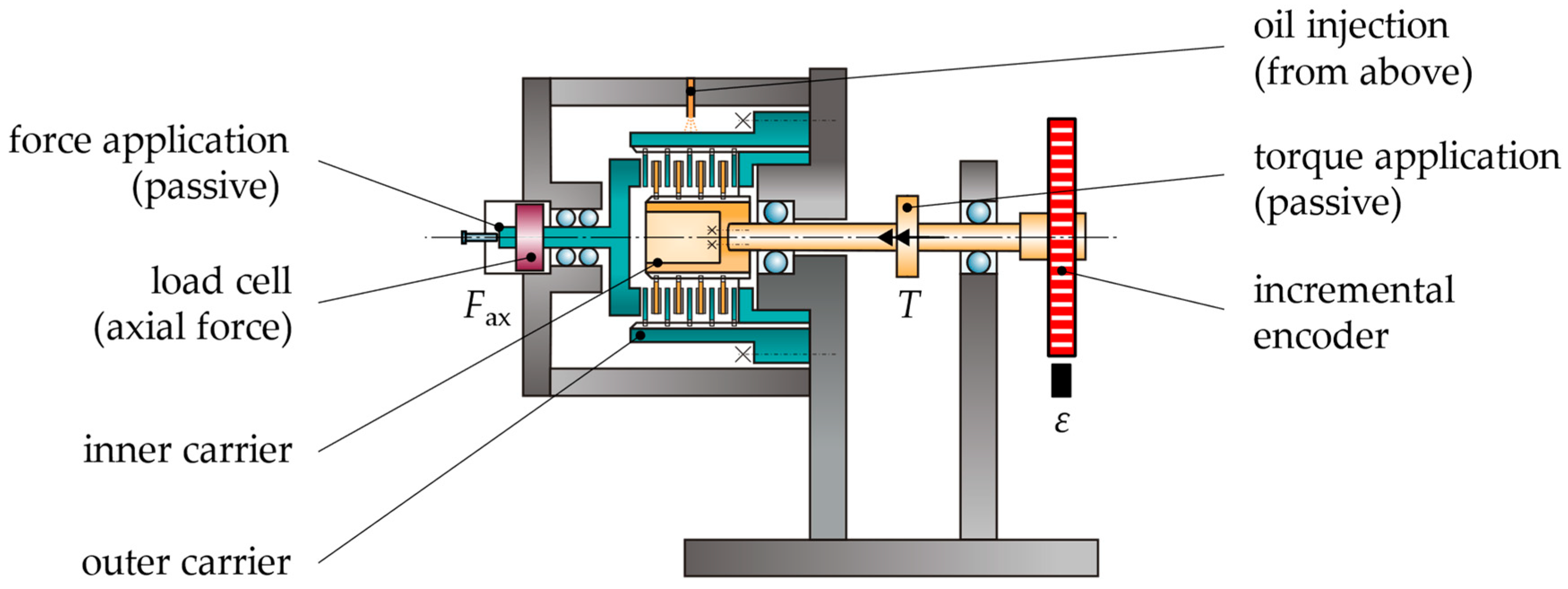
CoF at very low sliding velocities entails very different challenges. For this reason, a test rig especially suited for these challenges is recommended. In this context, test rig LK-3 can measure the friction behavior efficiently and precisely at the transition from static to dynamic friction. The passive force application applies an axial force
Fax on the clutch, measured via a load cell. The inner carrier is connected to a passive torque application that provides the torque
T. The angle
ε of the lever is measured over time via an incremental encoder. The evaluation only takes into account measurements within the range of −10° <
ε < 10° to remain in the valid area of the small-angle approximation. The temperature-controlled oil is injected from above.
Figure 2 shows a schematic sketch of the LK-3 test rig.
The clutch is actuated at first to investigate the friction behavior under micro-slip and static conditions. After that, the load torque
T is provided by a weight
m, connected to the inner shaft by a lever with the length
l. This weight mainly defines the operating point as a value of the utilized friction coefficient
UFC at an oil inlet temperature
ϑoil and a specific pressure
p. The
UFC is calculated as follows in Equation (2).
Each measurement is defined by an initially set value of the
UFC and results in an occurring creep rate over the measurement time. Therefore, the angle
ε allows for the calculation of the apparent sliding velocity for each point of investigation. The measurement time is mainly limited to around 15 min but can be extended with no limit for testing the long-term torque-transmitting capacity. The measurements are repeated for different values of the
UFC—commonly by changing the weight
m. If a measurement does not show any relevant creep rate, the measurement is rated as static. The maximum
UFC, up to which no relevant creep occurs, is called the static friction coefficient
SFC. All measurements showing a relevant creep rate are used for a curve fit of type f(
vs) =
a ∙
xb +
c with (0 <
b < 1) [
21]. The measurement uncertainty for the test rig also depends on the clutch size. It was discussed in detail previously [
7,
27].
2.3. Holistic Measurement Approach
The holistic measurement approach guarantees the application-relevant testing of the whole range of relevant sliding velocities occurring in the genuine application of the investigated friction systems. To provide this, the minimum and maximum relevant operating conditions of the test rig regarding oil or system temperature
ϑ and specific pressure
p must be derived from the genuine application. In the second step, the relevant range of the sliding velocity has to be defined. For this reason, three main categories, as shown in
Figure 3, according to the investigated ranges of the sliding velocity
vs are defined. These categories include micro-slip and static friction, low-speed slip, and brake shift operation. The exact boundaries between these categories depend on the specific test setup with parameters such as the clutch size, measurement accuracy, and speed control.
The mentioned categories can be tested in different operational modes, which mainly differ regarding the sequence in which the axial force
Fax, the friction torque
Tfr, and the differential speed ∆
n are applied to the system.
Figure 4 shows the four operational modes used in this investigation.
The clutch is actuated and loaded with a specific torque in micro-slip and static friction. This allows for the determination of very low sliding speeds due to the precise and stable torque loading. The clutch is also actuated first in the forced, low-speed slip operational modes and steady and transient slip modes. After that, the clutch is either tiered up to a defined steady differential speed or increased five times to a specific maximum differential speed ∆n. These modes allow for a different focus on the investigation. Brake shift mode allows for measurement at higher differential speeds, possibly leading to inadmissible energy input into the clutch if tested, e.g., in steady slip operation. Here, the clutch is accelerated to a maximum differential speed ∆n first and then actuated. During the transient phase of force application, the influence of the torque application must be considered.
A vital aspect of this paper is to provide an application-relevant test procedure suitable for different research objectives. Therefore, the methodology is adaptable to the needs of the specific application. The methodology is adaptable for other test rig setups and different operational modes but should always cover all application-relevant sliding velocities. It allows for the single analysis of each operational mode and the holistic study of friction behavior, which is defined by combining all necessary operational modes.
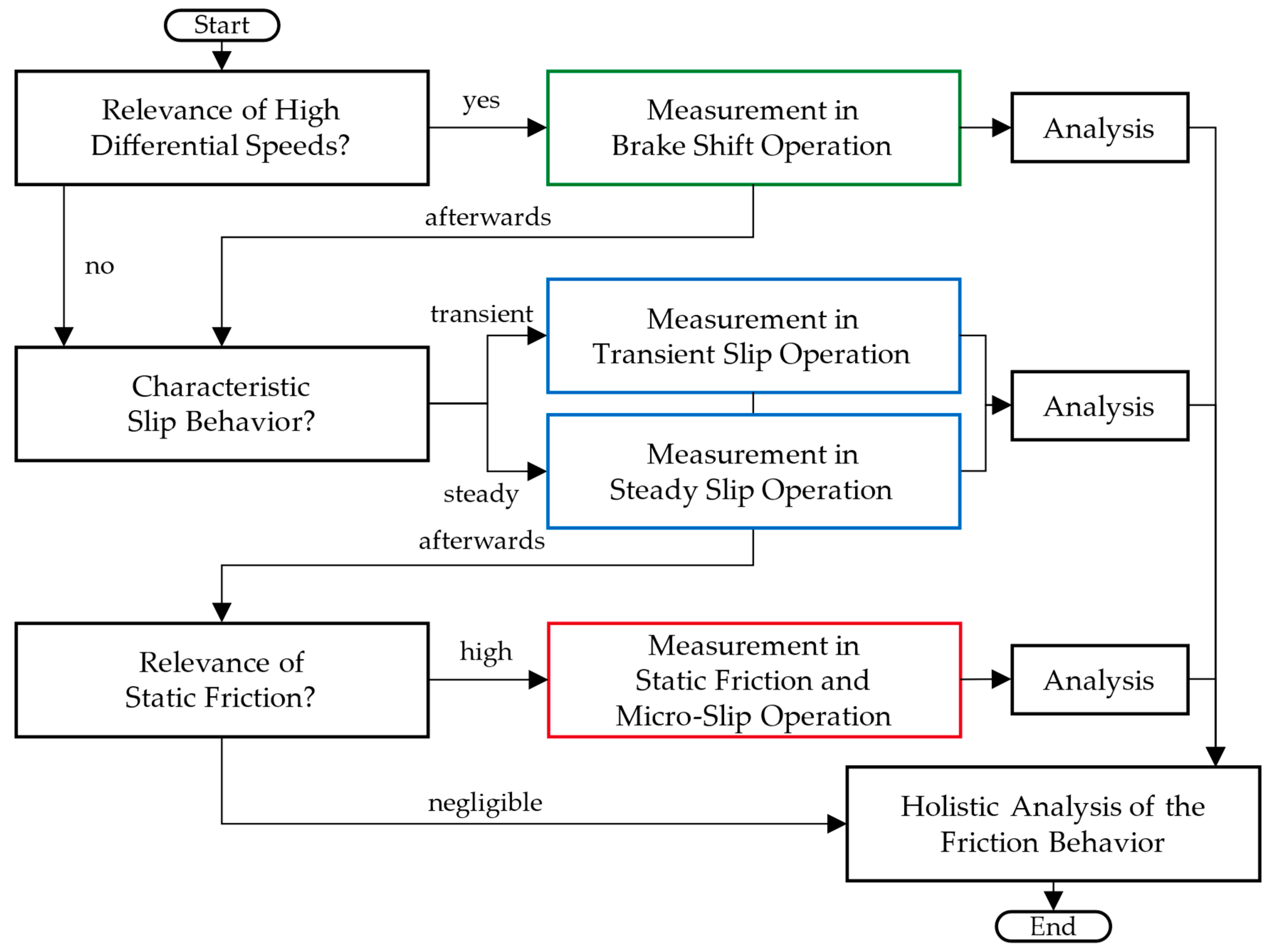
In
Figure 5, the design of a test and evaluation program is proposed considering the boundary conditions of the test rigs KLP-260 and LK-3. In the first step, the user has to decide if brake shifts should be investigated considering the relevance of high differential speeds or sliding velocities (
vs, max, forced slip > 1 m∙s
−1). After that, forced slip operation should be investigated according to the characteristic slip behavior in the genuine application, either in transient or steady slip mode. The investigation of the friction behavior in forced slip mode is obligatory. Depending on the relevance of the static friction in the intended application, measurements in micro-slip and static friction modes are performed.
2.4. Investigated Friction Systems
The results shown are based on experimental investigations with paper, sinter-metallic, and carbon friction linings, and application-relevant lubricants with different clutch sizes investigated in the research project no. 343 V, self-financed by the Research Association for Drive Technology e.V. (FVA) [
28]. Here, the described methodology was used for clutches from different applications. The following results concentrate on applying the holistic approach to measuring friction behavior in all relevant categories of the sliding velocity. The results shown are from run-in clutches. The run-in and exact procedure of the tests is described in previous publications [
28].
Table 1 gives an overview of the technical data of the parts used in the investigations. Each clutch size has a unique code (e.g., D155) denoting the mean friction diameter. All tests are performed with six friction surfaces (
z = 6).
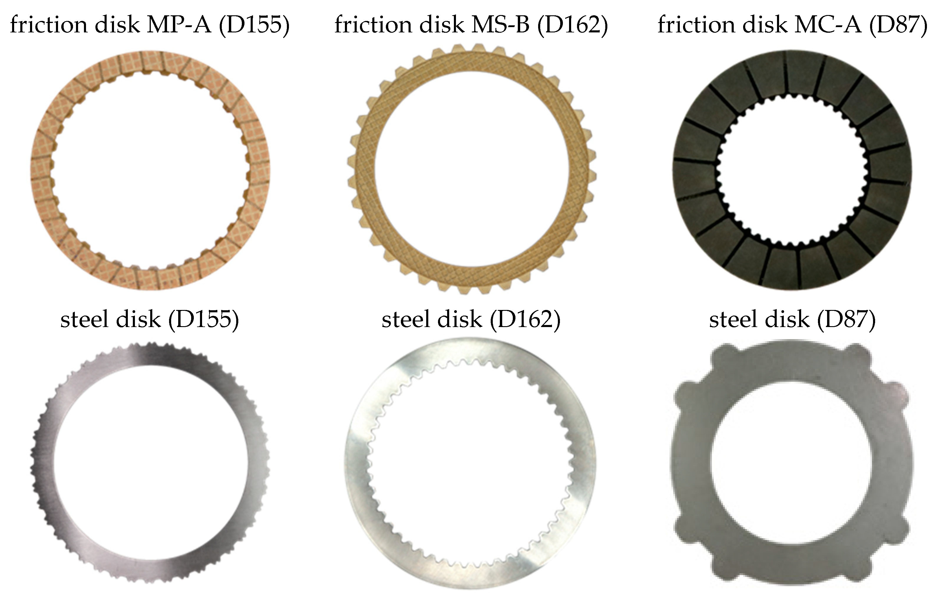
Figure 6 shows the friction and steel disks used for the investigations for the clutch sizes denoted in
Table 1. The shown measurements were performed with one friction system from a dual-clutch system (D155) with paper-based friction lining, from an industrial system (D162) with sinter-metallic friction lining, and from a limited-slip differential (D87) with carbon-containing friction lining. The steel disks of systems D87 and D155 are belt ground (bg), whereas the steel disks of systems D162 are cross ground (cg).
The outer disks are denoted with capital letters A–D, and the inner disks with lowercase letters a–c ascending on the side of the force actuation. The clutch temperature ϑ is measured with a NiCr-Ni thermocouple (type K) in one of the outer disks at around 45° from the vertical axis. Therefore, the corresponding tooth is removed, and a hole is drilled to the depth of the mean friction radius. For the paper-based friction system, the temperature is measured in the axial middle of steel disk B. For the sinter-metallic friction system, the temperature is measured in the axial middle of the friction disk B.
The investigations are performed with four application-relevant lubricants suitable for each friction lining and optimized for different objectives. Lubricant L-101 (dual-clutch) is tested with clutch system D155, lubricants L-201 and L-202 (axle gearbox) with clutch system D87, and lubricant L-301 (industrial) with clutch system D162. The technical data of the lubricants is given in
Table 2.
3. Results and Discussion
First, exemplary results from all operational modes are shown individually. After that, the combination of results from different sliding velocity-related categories and therefore different operational modes are shown. The focus of these results is to show the higher information content that the application of the proposed holistic methodology can obtain.
3.1. Friction and Temperature Behavior in Brake Shift Operation
In brake shift operation, the clutch temperature significantly influences the friction behavior due to the high energy input during engagement. Due to the different thermal conductivity of sinter-metallic and paper-based friction materials, the temperature behavior of both systems is different.
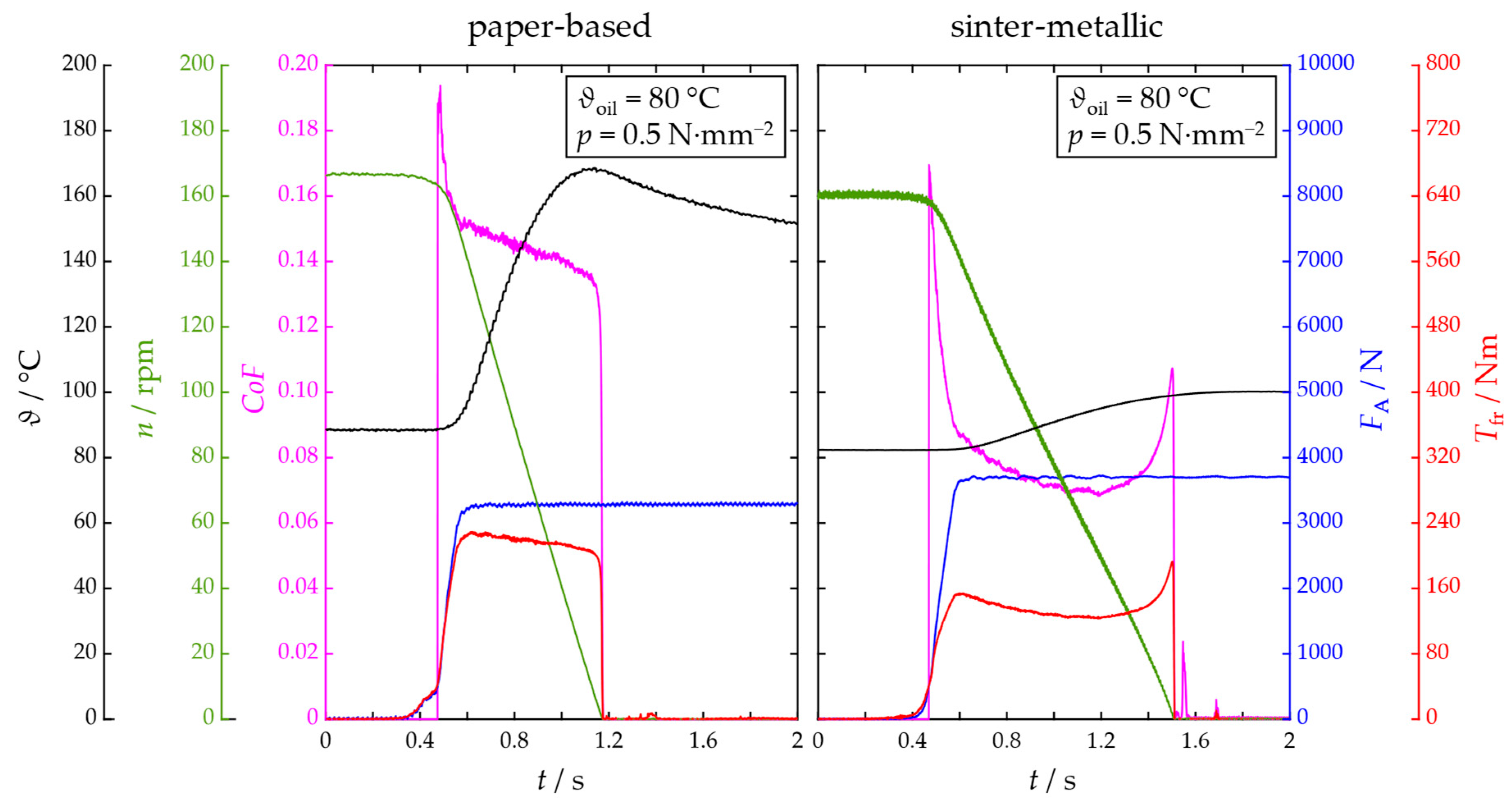
Figure 7 shows two measurements of the brake shift operation of a friction system, one with a paper-based and one with a sinter-metallic friction lining. The conditions of the clutches are chosen similarly. Still, they are not equivalent due to different friction work:
q = 0.2 J∙mm
−2 for the clutch with sinter-metallic friction material and
q = 0.25 J∙mm
−2 with paper-based friction material. Furthermore, the design of the friction system is not equivalent. Under consideration of this, the examples shown in
Figure 7 represent a more general comparison between both material groups concerning friction and temperature behavior than an exact comparison of the friction lining. It is possible to optimize and adapt the friction behavior of both systems, e.g., by using different lubricants or specific friction materials.
Figure 7 shows that the friction system with paper-based friction lining shows a comparatively high level of
CoF and a stable friction behavior with a positive friction characteristic. During the brake shift, the temperature
ϑ rises around 70 K, implicitly influencing the identified friction behavior. On the other hand, the friction behavior of the exemplary sinter-metallic system shows a negative friction characteristic, indicating an increased shudder tendency. Here, the
CoF level is generally lower but rises with lower sliding velocities. Due to the good thermal conductivity of the friction material, the rise of the clutch’s temperature
ϑ is significantly lower in this friction system. Nevertheless, a direct comparison of the temperature behavior of these systems is more qualitative due to different geometrical (e.g., clutch size, plate thickness) and materialistic properties of the outer disk (steel disk vs. friction disk).
At this point, an evaluation of the friction behavior in the form of a characteristic friction coefficient curve over the sliding velocity is omitted. However, this will be used later in the holistic analysis in
Section 3.4. Due to the influence of the clutch temperature, friction behavior at low speeds should be obtained using low-speed slip operation, as described in the following section.
3.2. Friction Behavior in Low-Speed Slip Operation
Steady or transient slip operation determines the friction behavior at low-speed slip. In steady slip operation, the
CoF is specified as its mean value over 25 s during the period of the forced steady slip of a total of five repetitions to minimize the influence of potential oscillations in the
CoF. The mean value is calculated according to Meingassner [
7], who also considers the oscillation of the sliding velocity. The resulting values are connected with straight lines.
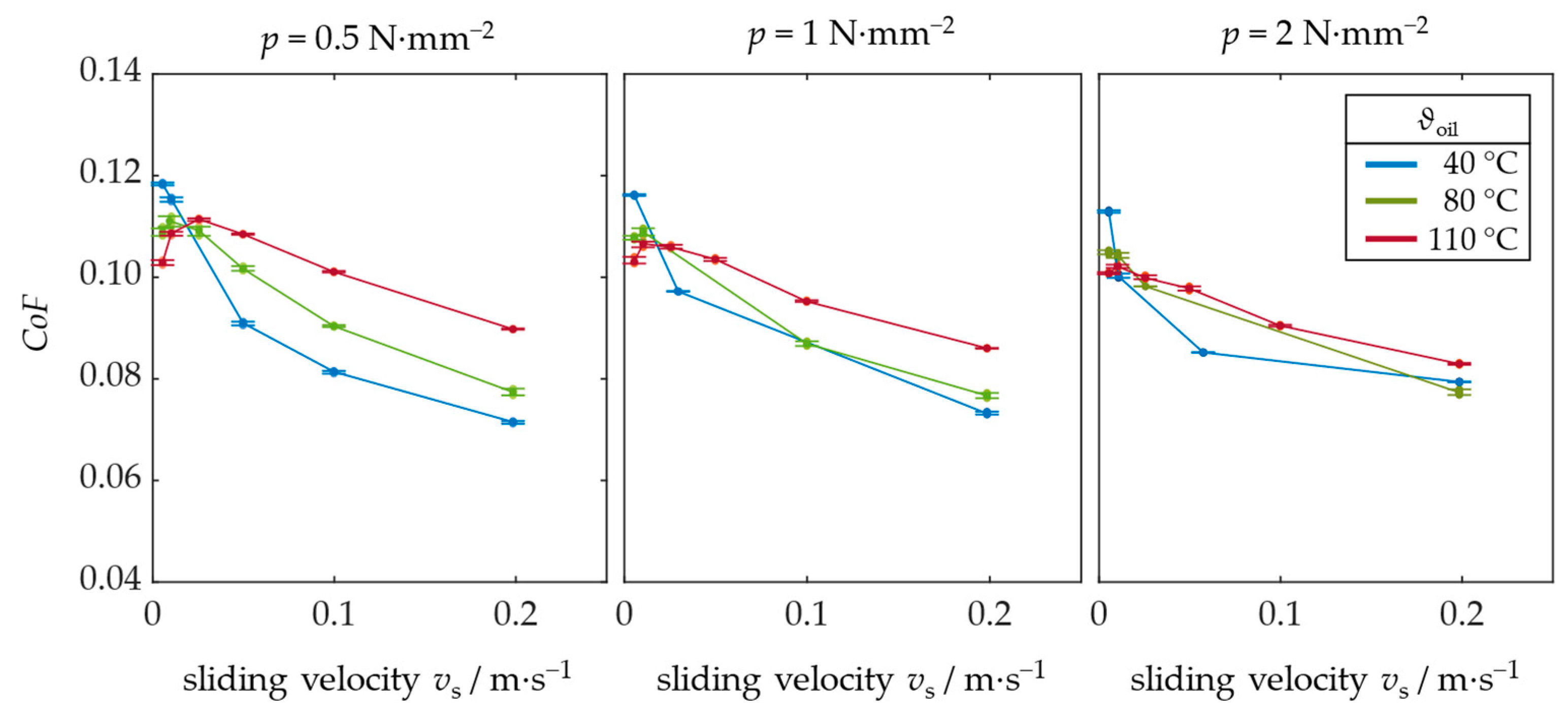
Figure 8 shows the friction behavior of an exemplary clutch system with sinter-metallic friction lining under steady conditions. Missing points (regular: six points per factor combination) indicate occurring shudder, which is critical for a stable investigation. The minimum and maximum
CoF values are depicted. It can be observed that the oil inlet temperature mainly influences the friction behavior and the NVH behavior due to the different gradients of the
CoF over sliding velocity. With higher temperatures, the increase in the
CoF towards lower sliding velocities is mitigated, leading to a distinct maximum of the
CoF in the range of the sliding velocities investigated.
Transient slip operation is recommended for automotive clutches, especially in the context of limited-slip differentials. Here, the higher information content can be used for a sound understanding of the course of the
CoF over sliding velocity v
s. The deaccelerating slip phases three and four of the transient slip mode are used from five repetitions to evaluate the sliding average of the
CoF over sliding velocity to mitigate the influence of oscillations of the
CoF. The method for this analysis is discussed by Strobl et al. [
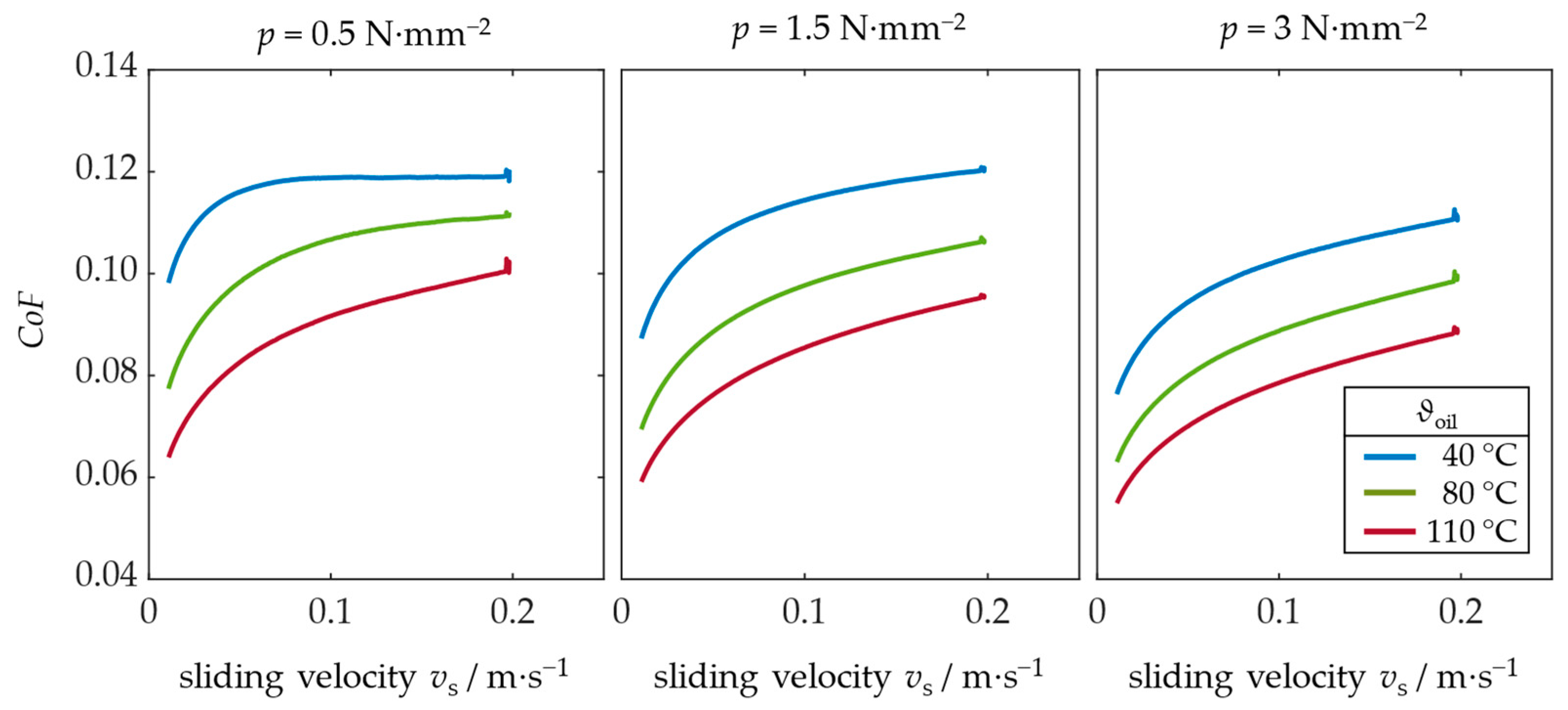
23]. The friction behavior from transient slip is shown in
Figure 9 for a friction system with carbon friction lining from limited-slip differentials.
The friction behavior shows a positive slope of the CoF over sliding velocity, indicating a low shudder tendency for all factor combinations. The oil temperature influences the friction behavior significantly, and the surface pressure influences the transmittable torque. Higher oil temperatures and higher surface pressure lead to lower CoF values.
3.3. Friction Behavior at the Transition from Static to Dynamic Friction
For typical friction systems, the friction behavior at the transition from static to dynamic friction is dominated by the approximately logarithmic behavior of the
CoF over sliding velocity
vs resulting from the usage of organic friction modifier additives, investigated, e.g., by Campen et al. [
2] and Ingram et al. [
1]. This leads to a smooth transition from static to dynamic friction and a static friction coefficient
SFC below the dynamic
CoF in low-speed slip operation. This transition can be observed for all friction systems investigated, which leads to the assumption that the lubricants contain corresponding additives.
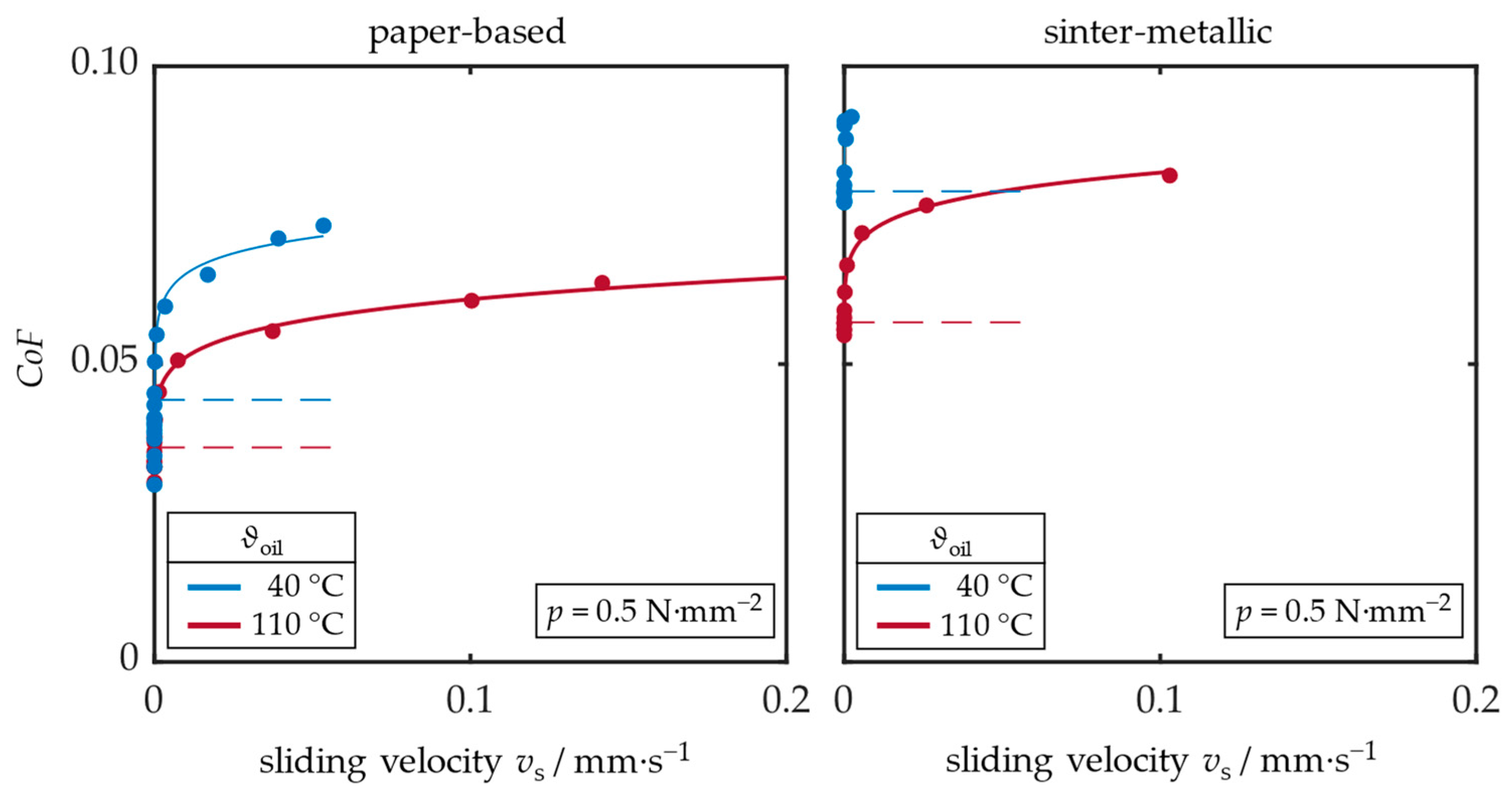
Figure 10 shows the friction behavior at the transition from static to dynamic friction for a friction system with paper-based (left) and sinter-metallic (right) friction lining for two oil temperatures. The
SFC values are indicated using dashed lines. The influence of the oil inlet temperature on the
CoF in micro-slip operation and the
SFC can be determined.
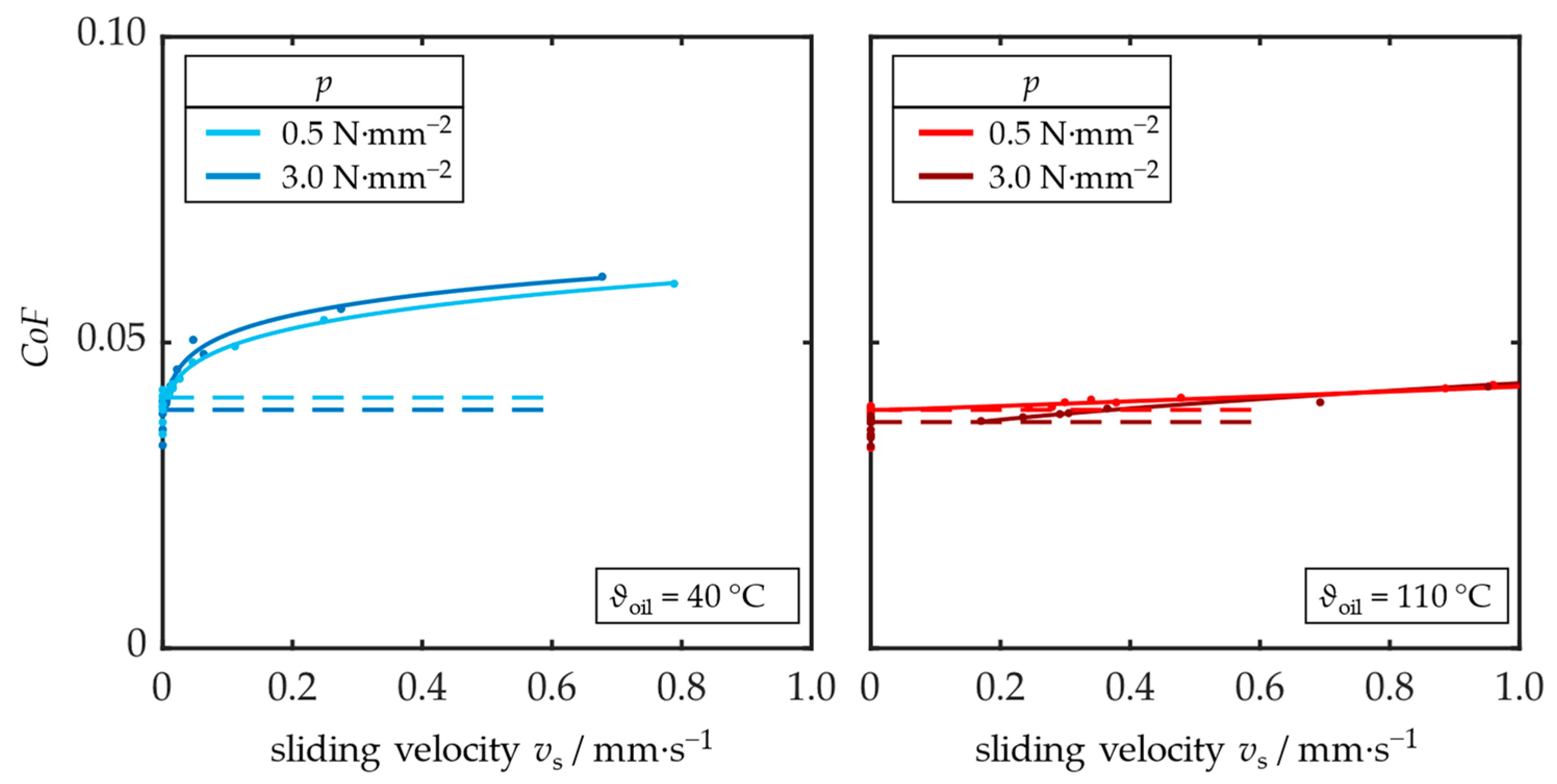
Nevertheless, some operating points abruptly transition from static to dynamic friction.
Figure 11 shows a different breakaway behavior for the two different oil inlet temperatures
ϑoil = 40 °C (left) and 110 °C (right). While at an oil inlet temperature of
ϑoil = 40 °C, the transition from static to dynamic friction is very smooth, the characteristic transition at
ϑoil = 110 °C shows an abrupt breakaway of the clutch characterized. In this case, the specific surface pressure p influences neither the
SFC values nor the oil inlet temperature
ϑoil.
In most investigations, the specific surface pressure p does not significantly influence the static friction coefficient SFC, whereas the influence on the CoF in micro-slip operation is higher. Nevertheless, the influence of the oil inlet temperature ϑoil is comparatively strong, leading to different friction behavior in micro-slip operation and even affecting the SFC of many friction systems.
3.4. Holistic Comparison of the Friction Behavior for Different Applications
The holistic methodology allows for the joint evaluation of the previously presented operational modes compactly. Here, the visualization by Meingassner [
26] is used to show the
CoF over the logarithmic sliding velocity v
s. The static torque-transmission capacity is indicated by the values of the
SFC.
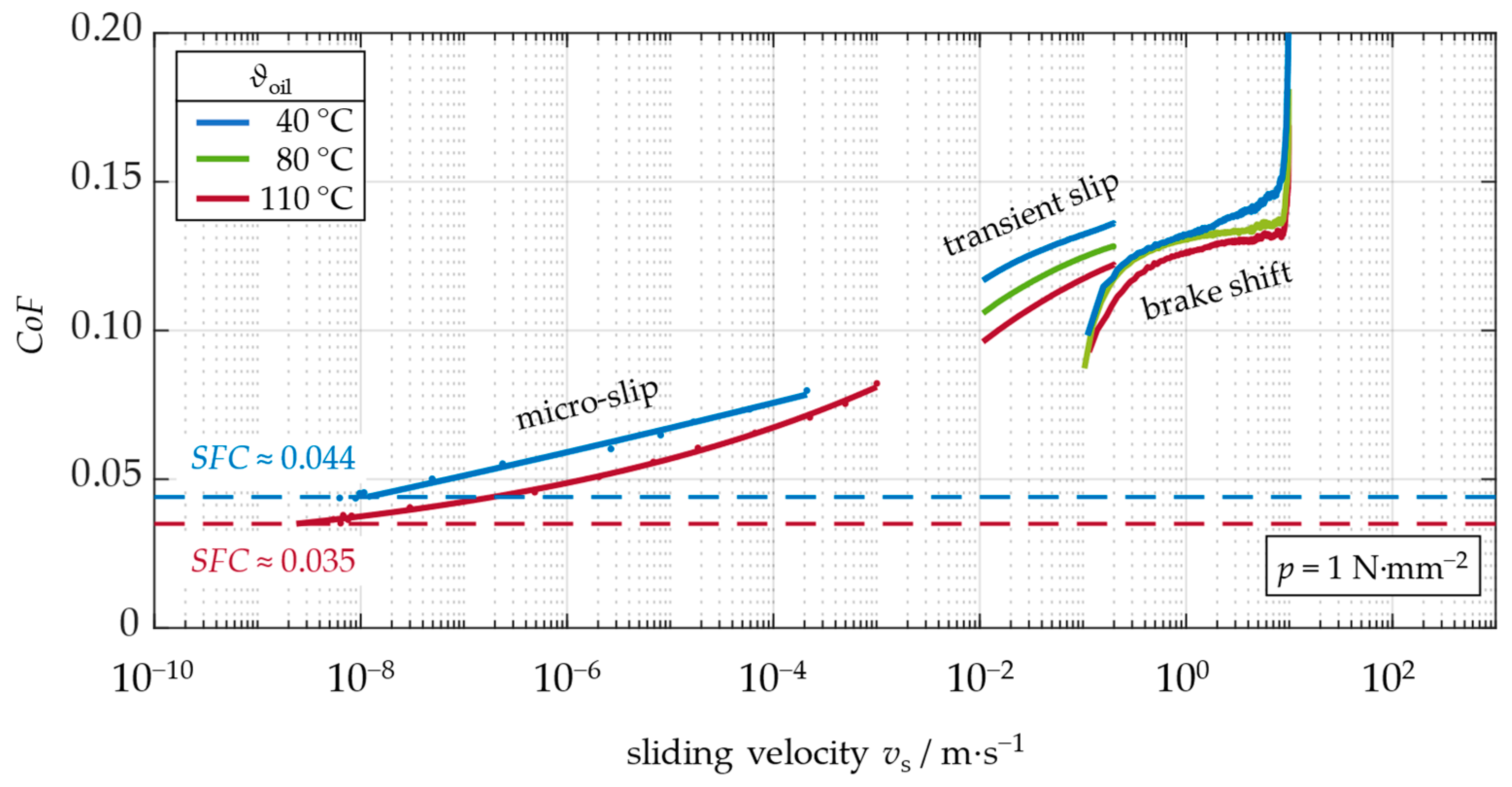
Figure 12 compares the friction behavior at different oil inlet temperatures in all relevant operational modes for a friction system with paper-based friction lining (MP-A) and a dual-clutch transmission lubricant (L-101).
In
Figure 12, the friction behavior at the highest speeds in the test is dominated by a peak in the
CoF, which is caused by the initial axial force build-up and therefore can be neglected for further interpretation. After that, the friction behavior shows a positive slope, indicating a good NVH behavior. During the brake shift, the clutch temperature rises significantly (see also
Figure 7), decreasing the
CoF for low sliding velocities. This decrease leads to an inconsistent transition between brake shift and low-speed slip operation. However, it is possible to show a strong connection over the system’s temperature by measuring the steel plate temperature.
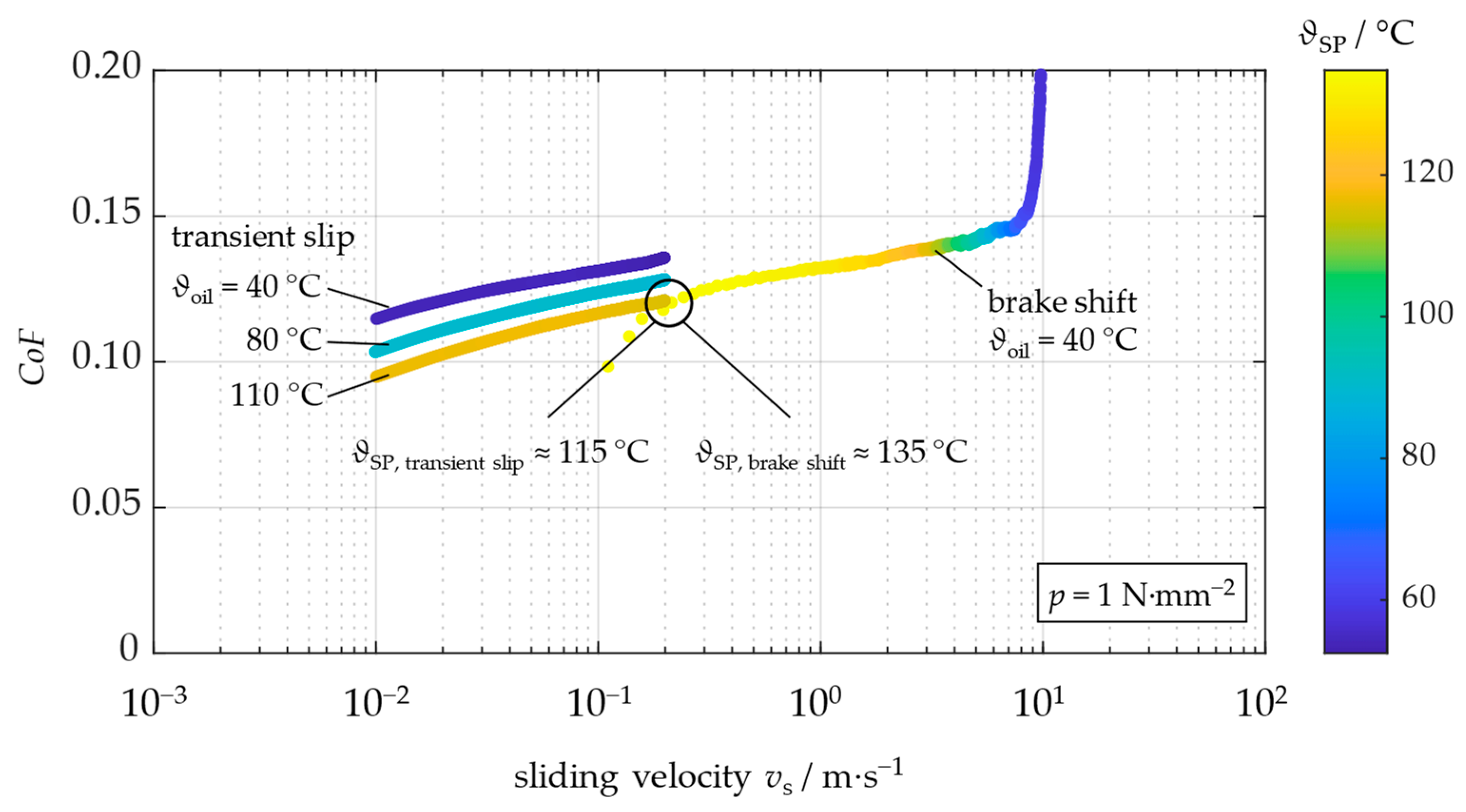
Figure 13 shows the brake shift at an oil inlet temperature of 40 °C and the measurements at different oil inlet temperatures in transient slip with additional color information on the steel plate temperature. At the transition from low-speed slip to brake shift operation, the steel plate’s temperature still differs by only 20 K. Nevertheless, the clutch temperature’s influence, as described by Maeki et al. [
29], can explain the different friction levels at the transition between these operational modes.
It can be assumed that the system’s temperature in micro-slip operation is slightly lower than the oil inlet temperature due to the low energy input and low friction work in this operational mode. The transition of the friction behavior from micro-slip to transient slip seems to be good, although the measurements could not close the gap between both operational modes. The holistic analysis shows a consistent decrease in friction behavior towards lower sliding velocities for the shown system.
This consistent decrease is typical for paper-based friction lining combined with fully formulated lubricants typical for automotive friction systems. Nevertheless, friction systems with sinter-metallic friction linings tend to show worse shudder tendency. These systems are mainly used in systems with lower requirements regarding comfortable shifting, such as industrial systems. The comparison between a representative automotive friction system with high requirements regarding reasonable control and NVH behavior and a robust industrial friction system with high shudder tendency is depicted in
Figure 14. Here, the holistic measurement allows for the evaluation of the friction behavior in the whole speed range, revealing a decrease in the
CoF that could not be evaluated using brake shift or low-speed slip operation. Measurements in micro-slip operation may support the safety-relevant design of clutch systems and allow for a data-driven decision on safety factors regarding static friction.
Besides the type of friction lining, the lubricant and additives it contains crucially influence the friction behavior of wet disk clutches in forced slip operation and micro-slip operation.
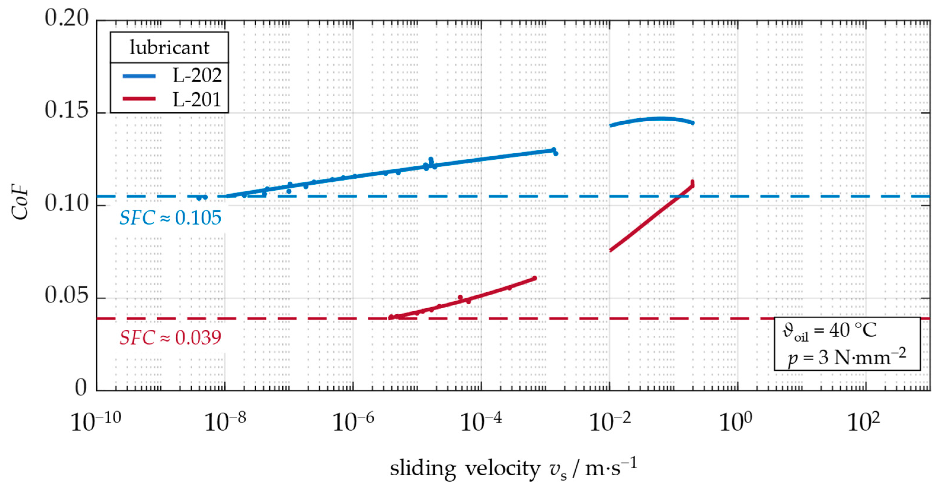
Figure 15 shows the influence of the lubricant for two friction systems from limited-slip differentials. No brake shifts were tested here due to their lack of relevance in the underlying application.
The comparison of the friction behaviors in micro-slip operation shows a considerable influence of the lubricant on the level of the static and dynamic CoF and the breakaway characteristics. For lubricant L-202, micro-slip operation is detected at very low sliding velocities around vs < 10−8 m∙s−1. For lubricant L-201, the clutch starts creeping at vs > 10−6 m∙s−1. A sole consideration of the friction behavior at low speed (or transient slip) cannot provide statements on the breakaway characteristics. Also, the decrease in the CoF over sliding velocity is very different for both lubricants, indicating the presence of friction-modifying additives. In addition, the SFC of both systems is lower than the values of the CoF for all relevant sliding velocities and is mainly affected by the lubricant.
4. Conclusions
The holistic measurement of friction behavior enables a more general evaluation of the functional behavior of wet disk clutches from torque-transmitting capacity without slip, breakaway characteristics, and the tendency of shudder up to the torque transmission at forced slip and brake shift operation. Due to the usage of optimized test rigs KLP-260 and LK-3, the methodology provides the measurement of the
CoF for low, moderate, and high sliding velocities. This guarantees the measurement of the friction behavior with high precision. The paper shows the exemplary application of the methodology for wet disk clutches from three different practical use cases. It extends previous findings to results from slip-controlled limited-slip differentials. The methodology is adaptable to various needs and research goals. For example, Strobl et al. use the methodology to identify the influence of the steel plate on the friction behavior [
23].
Due to increasingly stringent requirements for the efficient utilization of resources, the safety factors for dimensioning the clutch are getting smaller. For a reliable design of modern drivetrains, precise knowledge of the friction behavior at the transition from static to dynamic friction and at typically occurring sliding velocities is equally essential. All presented results indicate lower
CoF values at the transition from static to dynamic friction compared to traditional operational modes. Therefore, the characterization of the
SFC at defined sliding velocities (e.g., [
17]) or the end of a brake shift measurement (e.g., [
18]) might lead to a high uncertainty for the design of the clutch system and eventually cause unwanted slip in critical situations.
Stricter legislation in the context of particle emissions might lead to the need for automotive encapsulated wet brake systems [
30]. The friction behavior of this exemplary system should consider the holistic friction behavior to fully understand the friction behavior in the whole range of occurring sliding velocities v
s. But also, other clutch systems from all possible applications should be assessed considering the holistic measurement of the friction behavior to avoid unwanted slip and guarantee a reliable and comfortable friction system.

