Article

A Phenomenological Model for Estimating the Wear of Horizontally Straight Slurry Discharge Pipes: A Case Study

1
Key Laboratory of Urban Underground Engineering, Education Ministry, Beijing Jiaotong University, Beijing 100044, China
2
School of Civil Engineering, Beijing Jiaotong University, Beijing 100044, China
3
Faculty of Intelligent Manufacturing, Wuyi University, Jiangmen 529020, China
4
CCCC Tunnel Engineering Co., Ltd., Beijing 100024, China
*
Author to whom correspondence should be addressed.
Lubricants 2024, 12(6), 228; https://doi.org/10.3390/lubricants12060228
Submission received: 10 May 2024 / Revised: 7 June 2024 / Accepted: 10 June 2024 / Published: 19 June 2024
(This article belongs to the Special Issue Modeling and Characterization of Wear)

Abstract

:
When a slurry TBM advances in pebble and rock strata, large rock particles are carried in pipelines out of a tunnel by moving slurry. To estimate the wear of horizontally straight slurry discharge pipes, a phenomenological model was proposed that was mainly based on knowledge gained by means of direct and indirect in situ observations. The proposed model applies an equation composed of three variables, namely, the wear rate (λ), the central angle (2α), and the excavated tunnel length (L), to estimate the wear distribution along a pipe’s internal surface. The results indicated that wear mainly occurred on the bottoms of pipes. In addition, linear relationships between the maximum pipe wear amount (δmax) and the excavated tunnel length (L) were found for specific pipes and specified types of ground. The observed wear rates of different pipes in different types of ground had varied constants. The wear rates were higher for pipes in rock ground than for those in a pebble layer. For horizontally straight pipes, the observed wear rates were 0.0045 mm/m in a pebble layer and 0.0212 mm/m in rock ground. Lastly, to improve the proposed model, more field monitoring will be necessary to determine the pipe wear rates in different types of ground in the future.

1. Introduction

During slurry shield tunneling, excavated soils are conveyed in pipes by means of slurry transport [1,2,3]. During typical slurry shield tunneling operations in heterogeneous soils and rock ground, larger particles such as sand, gravel, cobble, boulder, and rock fragments must be expected [4,5], and the slurry used is usually a mixture of clay and bentonite or clay and natural soil that is suspended in water with other additives that are added for specific purposes [6,7,8,9]. The encountered particles, with sizes ranging from a few millimeters to tens of millimeters, are carried in pipelines out of a tunnel by the moving slurry [10]. During this hydraulic mucking process, pipeline wear is inevitable due to the frequent contact of the moving particles with the pipelines [11]. This wear will affect the lives of components and will cause leaks and even burst pipes if it is not well regulated, resulting in tunneling machine stoppages and extensions of construction schedules. Therefore, estimating slurry pipe wear is of great engineering significance for pipeline maintenance and management.
Hydraulic mucking, also called hydraulic transport, slurry transport, or slurry pipelining, is widely utilized in dredging [12,13,14,15], drilling, mining, etc., and involves the conveyance of solid particles in a suspension [16,17,18]. During these industrial applications, pipeline wear was found to be a significant limiting factor during the service life of a slurry pipelining system [19,20,21]. Table 1 indicates the correlations between factors influencing wear and the types of damage or wear that are possible. Many studies have been conducted to measure and predict wear in pipelines and associated pumping equipment [22,23,24]. More et al. [22] introduced an example of failure analysis for a coal ash slurry pipeline. The results indicated that failure occurred due to the impact of solid coal ash particles. Wang et al. [25] carried out indoor testing based on novel self-designed equipment to investigate the effects of flow velocity and coarse aggregate particle size. The results indicated that the wear rate increased in a power-law manner with both the flow velocity and the size of the coarse aggregate particles. Li et al. [26] conducted an in-depth analysis of elbow wear with the assistance of CFD-DEM modeling. The results showed that variations in sphericity did not change the location of the wall wear. Wang et al. [27] determined the effects of different filling slurry cement-to-tailings ratios and flow rates on pipeline wear based on indoor tests. The results indicated that the wear rate decreased with an increase in mass concentration and increased with growth in the flow rate.
In slurry shield tunneling, a slurry mainly consisting of bentonite and water rather than only water is usually adopted as a carrier. The transported rock particles, which are either natural particles from ground coarse grains or man-made particles from rock cutting using disc cutters in rock ground, are irregular in shape, large, and heavy. As a result, most of the particles cannot be suspended in the slurry and move on the pipeline’s inner surface, leading to more severe pipeline wear. However, research concerning slurry pipeline wear during slurry shield tunneling is rather limited, and two instances should be highlighted. The first instance involves the pipe wear caused by rock fragments of Bukit Timah granite at a slurry shield tunneling project in Singapore, where the relationship between the slurry discharge rate and the pipe wear rate was determined [28,29,30,31]. Another instance, in China, reported slurry pipeline wear and introduced measures against the wear [32,33,34,35].
According to the above analysis, the existing literature mainly focuses on the simulation of pipeline wear characteristics and the analysis of failure modes, and there are fewer phenomenological wear prediction models based on field measurements. When it comes to the wear of slurry discharge pipelines during slurry shield tunneling, three components are usually involved: abrasive particles; the material against which the particles impinge; and the relative impact, slide, or rolling velocity, which are influenced by the slurry flow. The transported particles and the movement of the particles in pipelines are influenced by many factors. Due to a general lack of reliable quantitative data on many of the factors affecting the wear of pipelines, predicting the wear or wear rates for new systems with reasonable certainty remains a demanding and challenging task. Based on direct and indirect in situ observations and the measured wear in pipelines at a slurry shield tunneling project in Beijing, China, the goal of this study was to build a phenomenological model to estimate the wear of slurry discharge pipes without detailed information being available on the nature of the fluid flow.

2. Project Overview

In this study, a case study in Beijing, China was used as a basis for the phenomenological model. The Tuan-Jiu part of the south-to-north water diversion project was constructed using a slurry shield machine, thus leading to the issue of hydraulic mucking. The longitudinal profiles of the soil and tunnel are described in Figure 1. The excavated ground has a total length of 1.7 km, and the involved soils at the job site can be divided into three sections according to the soil type, including an 848 m long section of cobble–clay mixed face, an 833 m long section of full bedrock face, and a 33 m long section of full clay face.
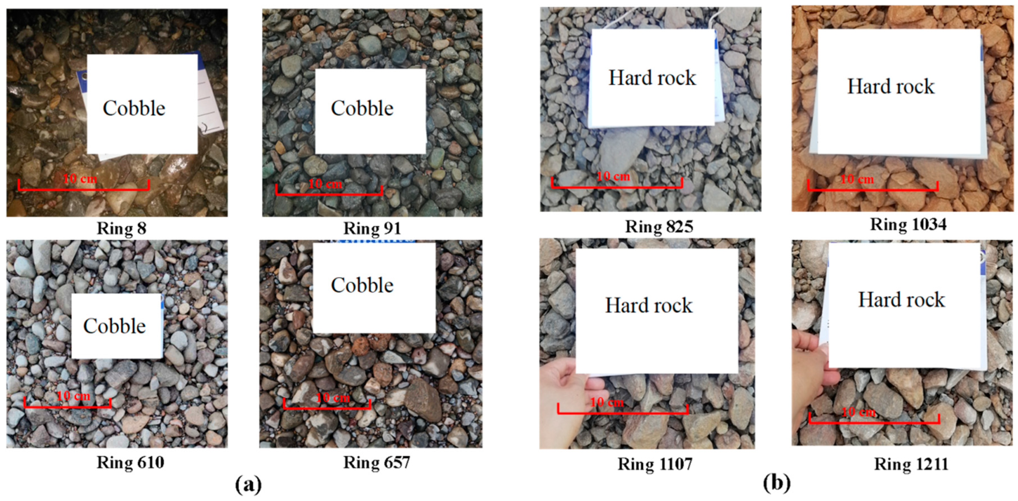
The slurry circulation system consists of pipes (Q235B mild steel) with an outer diameter of 300 mm and a wall thickness of 25 mm, elbows, centrifugal pumps, pipe joints, and gate valves, as described in Figure 2. To determine the wear rate of the pipeline, on-site field measurements were carried out, and the wear of the pipeline was measured using ultrasonic thickness gauges with an accuracy of 0.01 mm. Before the test began, the coupling agent was coated on the outer surface of the pipeline. Since the discharged muck contained a large amount of large hard particles, a knife gate valve was applied to disconnect the fluid when required. The ability of this valve to handle the fluid is attributed to the knife-edged disc. Figure 3a,b display the separated rock particles and pebble particles when the TBM was advancing in the rock and pebble strata, respectively. As described in Figure 3a, the separated pebble particles were usually spherical or sub-spherical, with a particle size of about 3–7 cm. Additionally, the separated rock particles were typically sharp-edged, with particle sizes of about 2–5 cm, as indicated in Figure 3b. Accordingly, the pipeline suffered severe wear and damage due to these hard and irregular particles being transported. This is not only dependent on the material properties of the particles, but also on the migration of the particles in the pipe. The former is mainly related to the excavated stratum and the shield machine used. In terms of the latter, both the size and weight of the particles being transported and the flow rate and rheological properties of the carrier fluid have significant effects on the migration of the particles in the pipe. In the water diversion tunnel project, the velocity of the carrier fluid applied in the pebble strata was in the range of 7–10 m3/min and was reduced to the range of 4–7 m3/min when tunneling in rock strata. In addition, the bentonite suspension was used as a carrier fluid to discharge the muck particles, and the rheological properties of the bentonite suspension were adjusted to adapt to the varied ground conditions during slurry shield advancement. Finally, the values of the slurry funnel viscosity and specific gravity fluctuated at 20 s and 1.15, respectively. More details about the project can be found in the study by Li et al. [36].
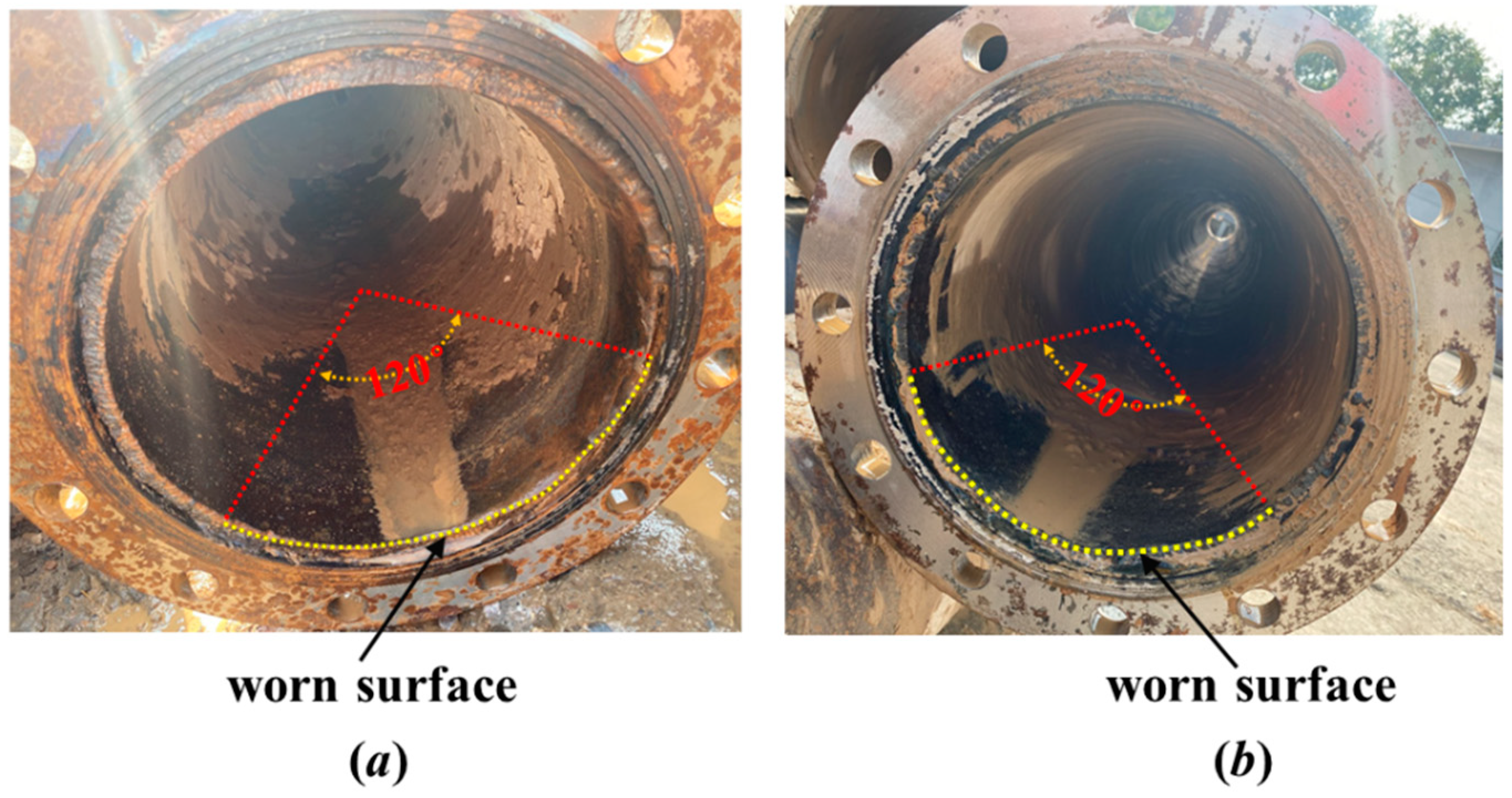
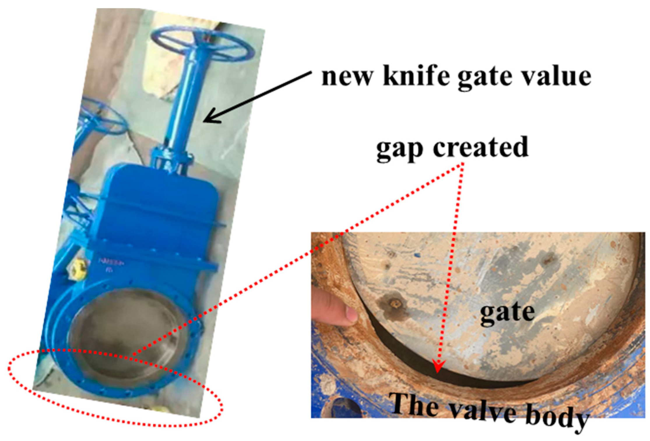
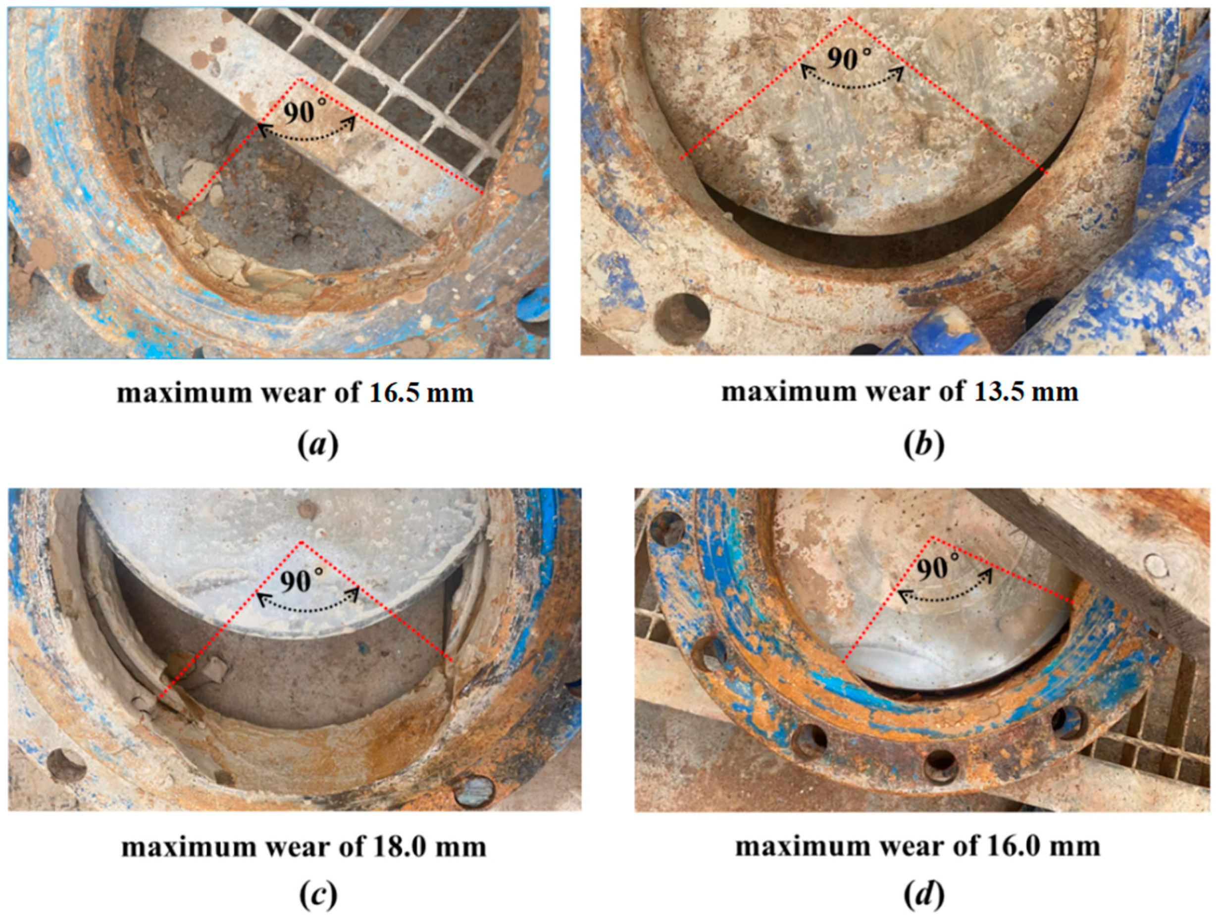
Large rock/pebble particles in the pipe make it difficult to achieve complete suspension under the action of its own gravity, and sliding, rolling, or fluctuations in the pipe inevitably result in the wear of the pipe and even in the slurry gushing during shield tunneling. As seen in Figure 4, the discharge pipe suffered serious abrasive wear and tear, the cumulative wear exceeded the wall thickness of the pipe, and the slurry in the pipe gushed. Figure 5 illustrates the worn-out pipelines used in the slurry shield circulation system. As can be observed in Figure 5, the bottom of the pipeline suffered the most severe wear and tear. In addition, a significant amount of wear occurred within the lower half of the pipe, which can be described by a central angle of 120°, as indicated in Figure 6. Additionally, the valve body was also subject to severe wear due to the frequent impacts of the transported rock/pebble particles, resulting in a large gap between the gate (the knife-edged disc) and the worn valve body and the seal failure of the knife gate valves, as depicted in Figure 7. Similar to the wear location of the pipeline, the wear location of the valve also occurred in the lower half, and the range of this wear can be defined with a central angle of about 90°, as shown in Figure 8.

3. Pipeline Wear Estimation Model

Based on the observed results shown in Figure 5, Figure 6, Figure 7 and Figure 8, two findings were attained: (1) the maximum wear is at the bottom of a pipeline; (2) the wear gradually decreases from the bottom to both sides along the internal surface of a pipeline and terminates at two specific locations within the lower half of a pipeline, and the worn range can be approximated with a specific central angle. In the following, the amount of wear is determined as the reduction in the radial thickness of a pipe’s walls.
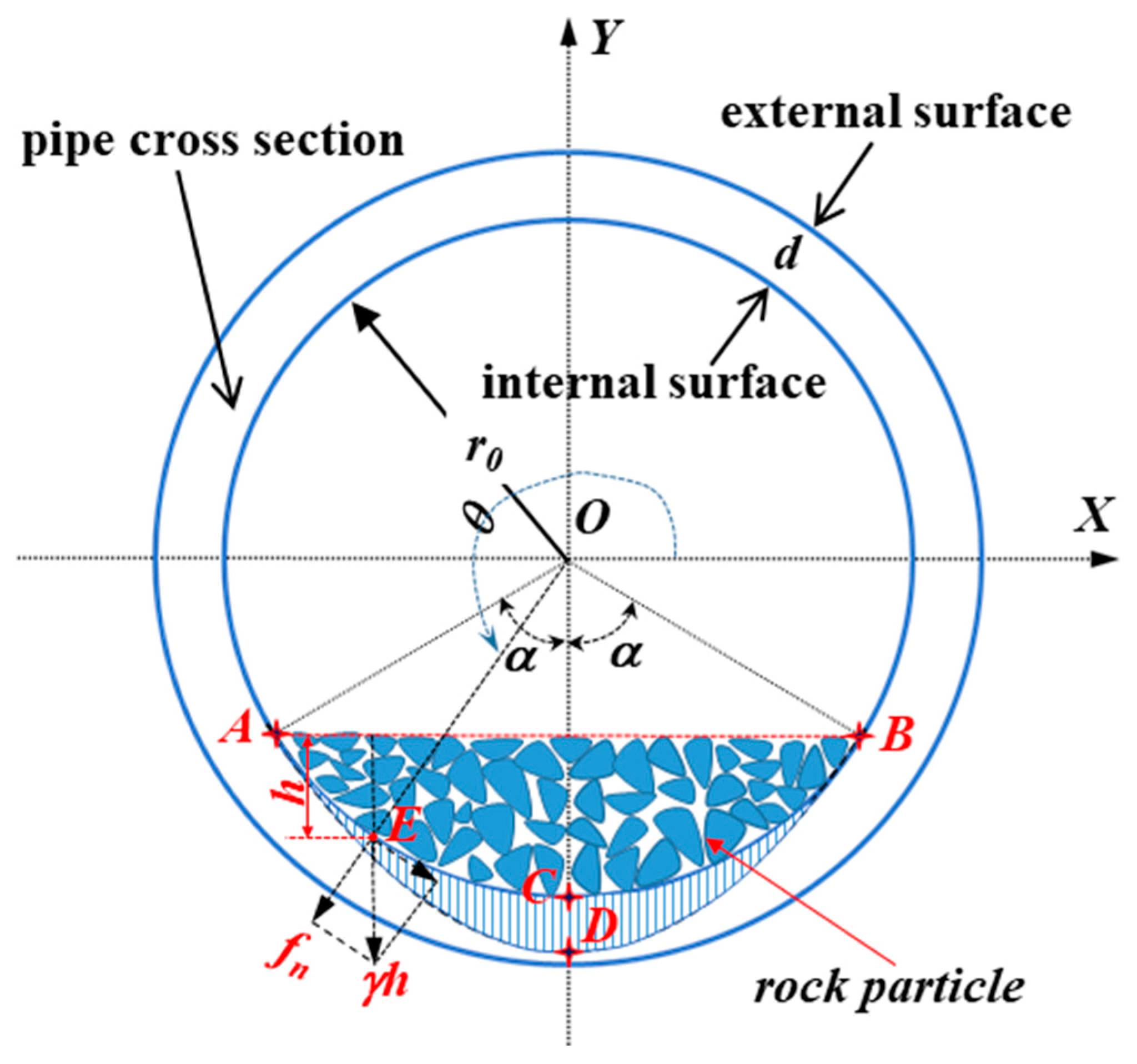
Referring to the two findings, the diagram used to estimate the pipe wear is presented in Figure 9. A cross section of a pipe with an internal radius of r0 and a wall thickness of d was employed. The moving rock particles inevitably cause wear to the bottom of the pipeline. The outlined area ADBC, filled with vertical lines within the lower half of the pipe, is the worn area, as shown in Figure 9.
The worn area between the initial surface, ACB, and the worn surface, ADB, can be defined by the central angle 2α, as shown in Figure 9. Wear occurs at the arc surface, AB, and the wear is zero at the two locations of A and B. The maximum wear amount, represented as δmax, takes place at point C and is the length of the line segment CD, shown in Figure 9. As to the wear, δ, at the other locations of the arc surface, AB, the following deduction is necessary. The wear is caused by the accumulated rock particles. This means that the wear amount is proportional to the normal force fn, which is caused by the accumulated rock particles at a point, such as point E, with a polar angle θ, shown in Figure 9. The normal force fn at point E is proportional to the gravity γh (γ and h are the equivalent specific gravity and height, respectively) of the accumulated rock particles. Taking γ as a constant and referring to Figure 9, the following relations can be established:
δ f n γ h cos 3 2 π θ
δ r 0 sin θ + cos α cos 3 2 π θ
A coefficient, k, is introduced to quantitatively define the pipe wear δ, and Equation (2) can be written as follows:
δ = k r 0 sin θ + cos α cos 3 2 π θ
where θ is 3π/2, and δ is δmax. Substituting these relations into Equation (3), the solution of k can be found:
k = δ max r 0 1 cos α
Thus, the equation to estimate the wear δ of a pipe can be expressed as
δ = δ max cos α + sin θ cos α 1 cos 3 2 π θ
With known values of α and δmax, the wear amount δ at the point with a polar angle θ can be determined.
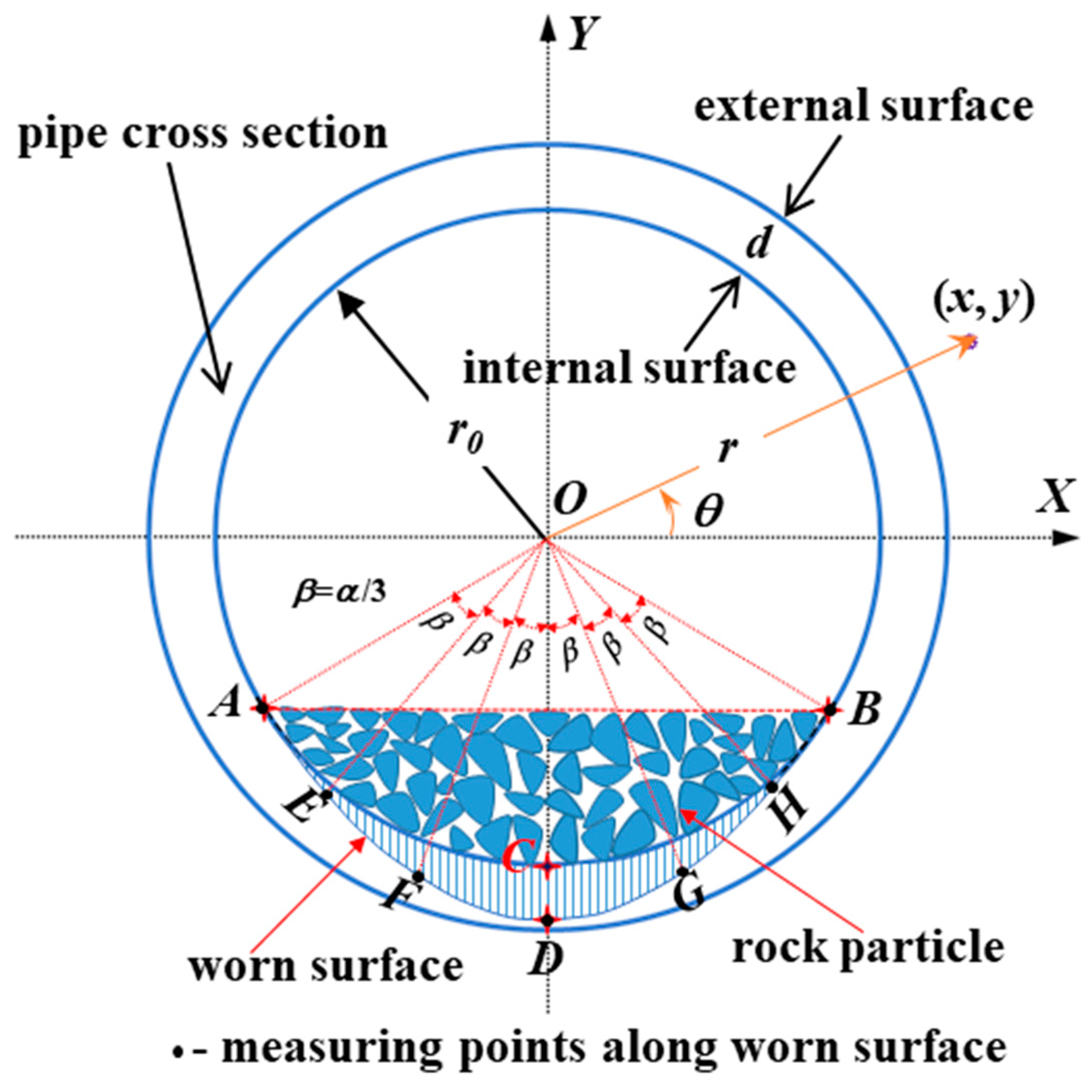
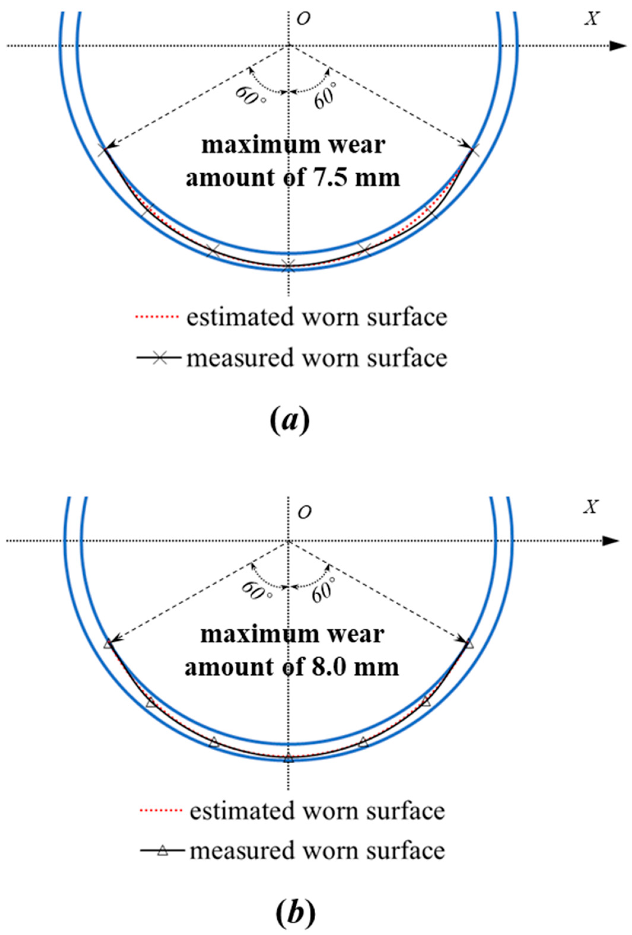
The amounts of wear at the seven points of the worn surface of the collected pipes in Figure 6 and the valves in Figure 8 were measured. The layout of the seven measuring points A, E, F, D, G, H, and B is shown in Figure 10. The central angles corresponding to the worn surface of the pipes in Figure 6a,b are about 120°. The measured maximum wear amounts of the pipes in Figure 6a,b are about 7.5 mm and 8.0 mm, respectively. The comparisons between the measured results of the two worn pipes with those estimated using Equation (4) are presented in Figure 11.
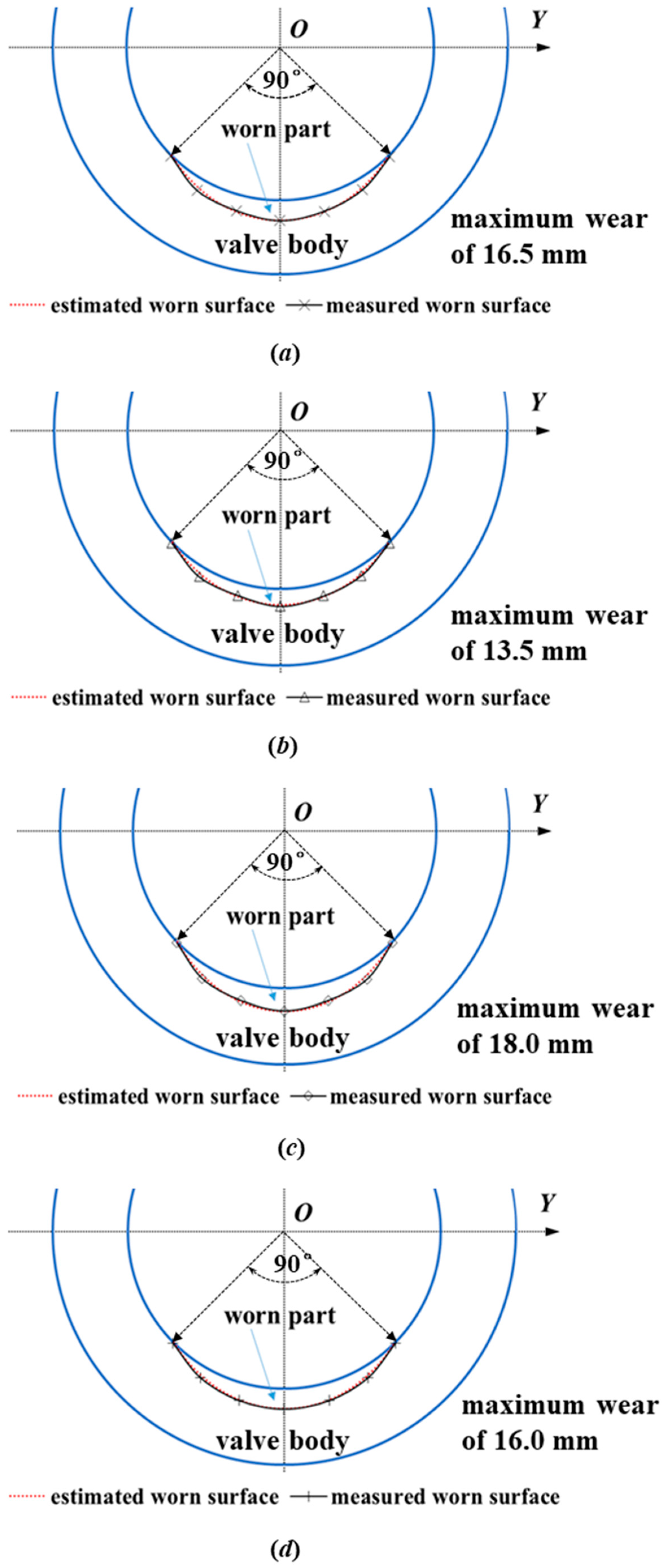
The central angles corresponding to the worn surface of the pipes in Figure 8a–d are about 90°. The measured maximum wear amounts of the valve bodies in Figure 8a–d are about 16.5 mm, 13.5 mm, 18.0 mm, and 16.0 mm, respectively. The comparisons between the measured results of the valve bodies and those estimated using Equation (5) are presented in Figure 12.
Figure 11 shows the comparisons between measured results and estimated results for pipes. Figure 12 shows the comparisons between measured results and estimated results for valves. The comparisons presented in Figure 11 and Figure 12 show good general agreement between the measured results and those estimated using Equation (5). For known wear values of α and δmax, Equation (5) can provide good approximations of the worn surfaces of the horizontally straight pipes and the knife gate valves’ bodies.
As presented in Figure 5 and Figure 8, the maximum wear, δmax, occurred at the lowest part of the pipe’s internal surface, and the wear, if not dealt with well, caused a gush of slurry at the pipe bottom. This phenomenon was widespread in the field, as shown in Figure 4, and was governed by the flow characteristics of the large rock particles in the pipe, as mentioned above. The bottom of the pipe suffered the largest impact of and most severe contact with the rock particles.
Regarding the wear amount of a pipe, it is the accumulated results of the rock particles’ contact with the pipe’s internal surface. The wear amount of a pipe wall is closely related to the amount of transported rock particles, which is decided by the excavated tunnel length for a predefined tunnel route and alignment. For different grounds, the effects of the sharpness, size, and hardness of the conveyed particles on pipe wear should also be taken into consideration.
To control the development of pipe wear with the shield machine advancement in the project, pipeline wear monitoring was carried out. Eight typical monitoring sites at four positions in the pipeline system, with two monitoring sites at each position, are presented herein. For two monitoring points in the same position, their average value was employed. Figure 13 demonstrates the recorded results.
It was observed that a linear relationship between the pipe wear, δmax, and the excavated tunnel length (accumulated segmental ring width), L, can be assumed for a given pipe and specified ground; the wear rate λ, i.e., the slope of a fitted straight line, is a constant, and the wear rates of the pipelines are higher in the rock ground. This means that the maximum wear amount, δmax, can be determined by multiplying the wear rate by the excavated tunnel length, which can be written as
δmax = λ·L
Equation (6) is substituted into Equation (5), producing the following:
δ = λ L cos α + sin θ cos α 1 cos 3 2 π θ
The pipe’s internal surface wear can be estimated with Equation (6) with the known λ and L. It remains a challenge to determine the wear rate, λ, for a given ground. The segment ring’s width was 1.2 m in this project. For the horizontal and straight pipe shown in Figure 13, the observed wear rates are 0.0045 mm/m in the pebble layer and 0.0212 mm/m in the rock ground, respectively. These two values can be employed to estimate pipe wear under similar conditions. More field monitoring is necessary to use Equation (6) to estimate pipe wear in the future.
As to the higher abrasiveness of the rock ground, this can be ascribed to the angularity of the rock fragments from the rock cutting using disc cutters. The mechanical effect of the angular rock particles on the inner wall of the pipe is more pronounced and produces more wear and tear on the pipe than the rounded and subrounded rock particles in pebbly strata. It was also found that different types of pipes had different wear rates in the same ground, and the 90° elbow pipe took the lead. This can be attributed to the different movements of the particles in the different pipes, as the pipes suffer from erosion wear when the bending angle is 90°. The different movements caused the varied contact of the particles with the pipe’s internal surface, and the 90° elbow pipe experienced the most severe contact.

4. Discussions

4.1. Flow Characteristics of Slurry and Rock Particles in Horizontally Straight Pipes

The rock particles conveyed in the pipelines at the jobsite were from the pebble layer and the rock ground. The moving slurry was laden with pebbles, cobbles, and broken boulders when tunneling in the former ground and with rock fragmentations when tunneling in the latter. The submerged weight of the rapidly settling particles involved in this slurry pipelining could not be carried using the fluid support mechanisms and had to be transferred downward by means of continuous or sporadic inter-granular contacts. The flow was fully stratified, with the large rock particles accumulating at the bottom of the pipeline, as shown in Figure 10. The transport of the large rock particles was the stratified coarse particle transport, and the large rock particles were concentrated in the lower portion of the pipe and would come into contact with each other and the pipe wall, thus causing wear of the pipe wall. The ratio ξ of the particle diameter to pipe diameter is of major importance in determining the presence of this stratified coarse particle transport type, which does not normally occur for a ξ below a certain value. Calculations carried out for narrow-graded slurries with water as a carrier fluid indicated a fully stratified behavior for values of ξ above 0.018 [37]. The threshold valve is expected to be larger to achieve this stratified coarse particle transport when the carrier is the bentonite suspension that was used in this project. The calculated values of ξ generally range from 0.12 to 0.28 for the particles presented in Figure 3a and from 0.08 to 0.20 for the particles presented in Figure 3b. There is no doubt that larger values of ξ gave rise to the movement of the transported rock particles in the lower portion of the pipe in this project. However, further studies on the threshold values of ξ are necessary when a bentonite suspension is used as the carrier in pipeline transport.

4.2. The Central Angle 2α Used to Define the Worn Area

As shown in Figure 10, the worn area of the pipe wall’s internal surface is heavily dependent on the amount of transported rock particles in a unit of time. The particles are created at the cutting face, and the amount of transported rock particles is decided by the advance rate of the tunneling shield machine and the rotation speed of the cutting head for predefined ground. Of course, the shape and arrangement of the in-pipe particles contribute to the porosity of the particles and influence the worn area.
The worn pipes presented in Figure 6 were used for the pebble layer. As a result of the shield machine’s penetration depth per revolution and the slurry’s velocity, the in-pipe pebble volumetric concentration was in the range of 0.18–0.24, causing the internal worn surface to have a central angle of about 120°, as depicted in Figure 6.
The worn valve bodies demonstrated in Figure 8 were used in the rock ground. The volumetric pebble concentration through the valve was about 0.08–0.12, thus leading to an internal worn surface with a central angle of around 90°, as shown in Figure 8. It is obvious that the worn area can be reduced by decreasing the volumetric rock particle concentration in the pipe and by reducing the shield machine’s penetration depth per revolution.

5. Conclusions

A phenomenological model was proposed for the wear estimation of the horizontally straight slurry discharge pipe of a tunneling slurry shield, mainly based on gaining knowledge by means of direct and indirect observations. As a result of this work, the major findings concerning slurry discharge pipe wear are as follows:
(1) In the proposed model, an equation composed of three variables, namely, the wear rate λ, the central angle 2α, and the excavated tunnel length L, is set up. Using the proposed model, the wear distribution along a pipe’s internal surface can be effectively estimated with the input of the proper parameters. The central angle, 2α, defining the pipe’s worn area, is dependent on the amount of transported rock particles in a unit of time and can be calculated using the volumetric content of the rock particles in the pipe.
(2) Wear mainly occurs at the bottom of the pipe. A linear relationship exists between the maximum pipe wear amount, δmax, and the excavated tunnel length, L, for a given pipe and specified ground. Different types of pipes had different wear rates in the same ground, and the 90° elbow pipe took the lead. This can be attributed to the different movements of the particles in the different pipes. The different movements caused the varied contact of the particles with the pipe’s internal surface, and the 90° elbow pipe experienced the most severe contact.
(3) The wear rate of pipes in the rock ground is higher than in the pebble layer. The reason for this is that angular rock fragments from rock cutting using a disc cutter in the rock strata have sharp edges and cause more wear and tear on the pipes compared with rounded and subrounded rock particles from the pebble strata. For a horizontally straight pipe, the observed wear rates of 0.0045 mm/m in the pebble layer and 0.0212 mm/m in the rock ground in this project can be employed to estimate pipe wear under similar conditions.
(4) To improve the proposed model, more field monitoring is necessary in the future to determine the wear rate in different ground.

Author Contributions

Conceptualization, X.L. (Xinggao Li) and Y.Y.; Methodology, X.L. (Xinggao Li), Y.G., X.L. (Xingchun Li), H.L. and Y.F.; Investigation, X.L. (Xinggao Li), Y.G., H.L. and Y.F.; Writing—original draft, X.L. (Xinggao Li), Y.G. and X.L. (Xingchun Li). All authors have read and agreed to the published version of the manuscript.

Funding

Fundamental Research Funds for the Central Universities No. 2023YJS053 and the National Science Foundation of China under Grant No. 52278386.

Data Availability Statement

Data will be made available on request.

Conflicts of Interest

Author Hongzhi Liu was employed by the company CCCC Tunnel Engineering Co., Ltd. The remaining authors declare that the research was conducted in the absence of any commercial or financial relationships that could be construed as a potential conflict of interest.

Abbreviations

r0Internal radius of pipe
dWall thickness of pipe
Central angle
δmaxMaximum wear amount
δWear amount
fnNormal force
γEquivalent specific gravity
hEquivalent specific height
θPolar angle
kWear coefficient
λWear rate
LExcavated tunnel length

References

  1. Cui, W.; Liu, D.; Song, H.F.; Pu, G.J. Development and experimental study on environmental slurry for slurry shield tunneling. Constr. Build. Mater. 2019, 216, 416–423. [Google Scholar] [CrossRef]
  2. Guo, Y.; Li, X.; Sun, Y.; Yang, Y.; Fang, Y.; Li, H. Investigation into the flow characteristics of slurry shield pipeline system under sandy pebble stratum: Model test and CFD-DEM simulation. Powder Technol. 2023, 415, 118149. [Google Scholar] [CrossRef]
  3. Yang, D.; Xia, Y.; Wu, D.; Chen, P.; Zeng, G.; Zhao, X. Numerical investigation of pipeline transport characteristics of slurry shield under gravel stratum. Tunn. Undergr. Space Technol. 2018, 71, 223–230. [Google Scholar] [CrossRef]
  4. Min, F.; Liu, J.; Chen, J.; Liu, T.; Yu, C.; Ji, J.; Liu, J. A study on the excavation face failure of pressurized slurry shield. Tunn. Undergr. Space Technol. 2023, 132, 104900. [Google Scholar] [CrossRef]
  5. Wang, D.; Min, F.; Lyu, H.; Chen, J.; Wang, B.; Zhang, J. Recycling waste sand from slurry shield tunneling: A sustainable filter aid for waste slurry dehydration. J. Clean. Prod. 2023, 383, 135387. [Google Scholar] [CrossRef]
  6. Min, F.; Zhu, W.; Lin, C.; Guo, X. Opening the excavation chamber of the large-diameter size slurry shield: A case study in Nanjing Yangtze River Tunnel in China. Tunn. Undergr. Space Technol. 2015, 46, 18–27. [Google Scholar] [CrossRef]
  7. Göbl, A. Swinoujscie Tunnel—Using a slurry shield under the Baltic Sea. Geomech. Tunn. 2021, 14, 708–717. [Google Scholar] [CrossRef]
  8. Wendl, K.; Scholz, M.; Thuro, K. Charakterisierung der ingenieurgeologischen Vortriebsdokumentation von Hydroschildvortrieben am Beispiel der Baulose H3-4 und H8 im Unterinntal. Geotechnik 2012, 35, 168–176. [Google Scholar] [CrossRef]
  9. Fritz, P. Additives for slurry shields in highly permeable ground. Rock Mech. Rock Eng. 2007, 40, 81–95. [Google Scholar] [CrossRef]
  10. Chan, L.K.L.; Kwong, A.K.L. Geotechnical risks, mitigation measures and performance of tunnel boring machine (TBM) tunnels for the Tuen Mun—Chek Lap Kok Link Project. HKIE Trans. 2019, 26, 175–189. [Google Scholar] [CrossRef]
  11. More, S.R.; Ingole, S.P.; Bhatt, D.V.; Menghani, J.V. The study of slurry erosion wear behaviour of coal bottom ash slurry handling pipeline. In TMS 2019, 148th Annual Meeting & Exhibition Supplemental Proceedings, Proceedings of the Minerals, Metals and Materials Society Meeting, San Antonio, TX, USA, 10–14 March 2019; Springer International Publishing: Cham, Switzerland, 2019; pp. 697–710. [Google Scholar]
  12. Grewal, H.S.; Singh, H.; Agrawal, A. A phenomenological model for slurry erosion prediction of thermal spray coatings. Tribol. Lett. 2014, 56, 119–132. [Google Scholar] [CrossRef]
  13. Summer, R.M. A review of pipeline slurry erosion measurements and research recommendations. In Slurry Erosion: Uses, Applications, and Test Methods; ASTM International: West Conshohocken, PA, USA, 1987; pp. 91–100. [Google Scholar]
  14. Singh, V.; Kumar, S.; Mohapatra, S.K. Modeling of erosion wear of sand water slurry flow through pipe bend using CFD. J. Appl. Fluid Mech. 2019, 12, 679–687. [Google Scholar] [CrossRef]
  15. Oka, Y.I.; Okamura, K.; Yoshida, T. Practical estimation of erosion damage caused by solid particle impact, Part 1: Effects of impact parameters on a predictive equation. Wear 2005, 259, 95–101. [Google Scholar] [CrossRef]
  16. Oka, Y.I.; Yoshida, T. Practical estimation of erosion damage caused by solid particle impact, Part 2: Mechanical properties of materials directly associated with erosion damage. Wear 2005, 259, 102–109. [Google Scholar] [CrossRef]
  17. Pereira, G.C.; Souza, F.; Martins, D. Numerical prediction of the erosion due to particles in elbows. Powder Technol. 2014, 261, 105–117. [Google Scholar] [CrossRef]
  18. Arabnejad, H.; Mansouri, A.; Shirazi, S.A.; McLaury, B.S. Development of mechanistic erosion equation for solid particles. Wear 2015, 332–333, 1044–1050. [Google Scholar] [CrossRef]
  19. Rawat, A.; Singh, S.N.; Seshadri, V. Erosion wear studies on high concentration fly ash slurries. Wear 2017, 378, 114–125. [Google Scholar] [CrossRef]
  20. Coker, E.H.; Peursem, D.V. The erosion of horizontal sand slurry pipelines resulting from inter-particle collision. Wear 2018, 400, 74–81. [Google Scholar] [CrossRef]
  21. Javaheria, V.; Portera, D.; Kuokkalab, V. Slurry erosion of steel—Review of tests, mechanisms and materials. Wear 2018, 408, 248–273. [Google Scholar] [CrossRef]
  22. More, S.R.; Bhatt, D.V.; Menghani, J.V. Failure analysis of coal bottom ash slurry pipeline in thermal power plant. Eng. Fail. Anal. 2018, 90, 489–496. [Google Scholar] [CrossRef]
  23. Huard, M.; Adane, K.F. Validation of a dense slurry pipeline erosion-corrosion model. In Proceedings of the Corrosion 2020, Online, 14–18 June 2020; pp. 1545–1559. [Google Scholar]
  24. Singh, J. A Review on mechanisms and testing of wear in slurry pumps, pipeline circuits, and hydraulic turbines. J. Tribol. 2021, 143, 090801. [Google Scholar] [CrossRef]
  25. Wang, X.; Guo, J.; Wu, A.; Wang, H.; Jiang, H.; Li, Z.; Qiu, Z. Wear characteristics of the pipeline transporting cemented paste backfill containing coarse aggregate. Constr. Build. Mater. 2024, 410, 134170. [Google Scholar] [CrossRef]
  26. Li, Z.; Chen, H.; Wu, Y.; Xu, Z.; Shi, H.; Zhang, P. CFD-DEM analysis of hydraulic conveying of non-spherical particles through a vertical-bend-horizontal pipeline. Powder Technol. 2024, 434, 119361. [Google Scholar] [CrossRef]
  27. Wang, Y.; Wang, Y.; Yang, G.; Ruan, Z.; Wang, Z. Effect of cement-to-tailings ratio and flow rate on the wear performance of filling pipeline. Powder Technol. 2022, 397, 117027. [Google Scholar] [CrossRef]
  28. Pak, Y.T.; Kim, T.K.; Ko, T.Y. A study on the discharge pipes wear of slurry shield TBM in rock strata. J. Korean Tunn. Undergr. Space Assoc. 2017, 19, 57–70. (In Korean) [Google Scholar] [CrossRef]
  29. Ko, T.Y.; Pak, Y.T.; Yoon, D.H.; Kim, S.; Kim, T.K. Slurry pipe wear in shield TBM, YSRM 2017 & NDRMGE 2017. In Proceedings of the ISRM Specialized Conference, Jeju, Republic of Korea, 11–13 May 2017; pp. 458–460. [Google Scholar]
  30. Ko, T.Y.; Pak, Y.T.; Kim, T.K.; Son, S. Effect of rock abrasiveness on slurry shield tunneling. In Proceedings of the International Conference on Tunnel Boring Machines in Difficult Grounds (TBM DiGs), Wuhan, China, 20–22 November 2017. [Google Scholar]
  31. Ko, T.Y.; Lee, S.S. Effect of rock abrasiveness on wear of shield tunnelling in Bukit Timah Granite. Appl. Sci. 2020, 10, 3231. [Google Scholar] [CrossRef]
  32. Wang, F. The difficulties and countermeasures in shield construction of Yellow River tunnel of Lanzhou Metro Line 1. Railw. Stand. Des. 2017, 61, 93–99. (In Chinese) [Google Scholar]
  33. Huang, B.; Li, X.; Chen, C. Study of abrasion of slurry pipe of large-diameter slurry shield boring in complex strata. Tunn. Constr. 2016, 36, 490–496. (In Chinese) [Google Scholar]
  34. Dong, B. Countermeasures for reducing wear and vibration of slurry pipe of slurry shield. Tunn. Constr. 2016, 36, 1385–1388. (In Chinese) [Google Scholar]
  35. Hou, B.; Xu, Z.; Hu, X.; Guo, G. Analysis of technical difficulties and control measures for slurry shield boring in sandy cobble strata: A case study of Yellow River crossing tunnel of Lanzhou Metro. Tunn. Constr. 2018, 38, 846–850. (In Chinese) [Google Scholar]
  36. Li, X.; Fang, Y.; Guo, Y.; Li, X. Slurry Discharge Pipeline Damage and Wear Due to Transporting Rock Particles during Slurry Shield Tunneling: A Case Study Based on In Situ Observed Results. Appl. Sci. 2023, 13, 7103. [Google Scholar] [CrossRef]
  37. Wilson, K.C.; Addie, G.R.; Sellgren, A.; Clift, R. Slurry Transport Using Centrifugal Pumps, 3rd ed.; Springer: New York, NY, USA, 2006. [Google Scholar]
Figure 1. Longitudinal profile of ground and tunnel.
Lubricants 12 00228 g001
Figure 2. Main components of slurry circulation system [36].
Lubricants 12 00228 g002
Figure 3. Separated particles (a) when shield tunneling in the pebble layer and (b) when shield tunneling in the rock ground.
Lubricants 12 00228 g003
Figure 4. Pipeline slurry gushing [36].
Lubricants 12 00228 g004
Figure 5. Worn-out pipelines.
Lubricants 12 00228 g005
Figure 6. Worn internal surface of pipes.
Lubricants 12 00228 g006
Figure 7. Worn knife gate valves.
Lubricants 12 00228 g007
Figure 8. Worn valve body.
Lubricants 12 00228 g008
Figure 9. A diagram of the pipe wear estimation model.
Lubricants 12 00228 g009
Figure 10. The layout of the seven measuring points.
Lubricants 12 00228 g010
Figure 11. Comparisons between measured results and estimated results for pipes.
Lubricants 12 00228 g011
Figure 12. Comparisons between measured results and estimated results for valves.
Lubricants 12 00228 g012
Figure 13. In situ measured wear in pipelines.
Lubricants 12 00228 g013
Table 1. Correlations between factors influencing wear and the types of damage or wear that are possible.
Influencing FactorType of Possible Damage or WearDescription
Material HardnessAbrasive WearSofter materials are more prone to abrasive wear from hard particles.
Mechanical VibrationFatigue WearVibration induces cyclic stress, causing material fatigue damage.
Corrosive EnvironmentCorrosive WearCorrosive media accelerate material damage by combining with wear processes.
Environmental TemperatureThermal FatigueHigh temperatures cause thermal fatigue, leading to cracks or spalling.
Fluid VelocityErosion WearErosion wear results from the high-velocity impacts of fluids (especially those containing solid particles) on the inner wall. This type of wear typically occurs at pipeline bends, diameter changes, or areas with abrupt flow rate changes.
Disclaimer/Publisher’s Note: The statements, opinions and data contained in all publications are solely those of the individual author(s) and contributor(s) and not of MDPI and/or the editor(s). MDPI and/or the editor(s) disclaim responsibility for any injury to people or property resulting from any ideas, methods, instructions or products referred to in the content.