Article

Evaluation of the Degree of Degradation of Brake Pad Friction Surfaces Using Image Processing

1
Department of the Theory of Wave Processes and Optical Systems of Diagnostics, Karpenko Physico-Mechanical Institute of the NAS of Ukraine, 79060 Lviv, Ukraine
2
Department of Software, Lviv Polytechnic National University, 79013 Lviv, Ukraine
3
Department of Computer Sciences, University of Lodz, 90-236 Lodz, Poland
4
Department of Manufacturing Systems, Faculty of Mechanical Engineering and Robotics, AGH University of Krakow, 30-059 Krakow, Poland
5
Department of Road Transport, Ivano-Frankivsk National Technical University of Oil and Gas, 76019 Ivano-Frankivsk, Ukraine
6
Department of Computerized Mechanical Engineering, Ivano-Frankivsk National Technical University of Oil and Gas, 76019 Ivano-Frankivsk, Ukraine
*
Author to whom correspondence should be addressed.
Lubricants 2024, 12(5), 172; https://doi.org/10.3390/lubricants12050172
Submission received: 6 March 2024 / Revised: 6 May 2024 / Accepted: 8 May 2024 / Published: 11 May 2024

Abstract

:
The improvement of drilling rig systems to ensure a reduction in unproductive time spent on lowering and lifting operations for replacing drilling tools and restoring the performance of drilling equipment units is an important task. At the same time, considerable attention is paid to the reliable and efficient operation of the braking systems of drilling rig winches. In the process of operation, the polymer pads periodically come into contact with the outer cylindrical surface of the metal pulley during braking, work in extreme conditions and wear out intensively, so they need periodic replacement. Tests were carried out on a modernized stand and in industrial conditions for the brakes of drilling winches. A methodology for evaluating the degradation of the brake pad friction surface during its operation is proposed. The assessment of the degradation degree is carried out based on the image of the brake pad surface using image processing techniques. Geometric transformations of the input image were performed to avoid perspective distortions caused by the concave shape of the brake pads and the spatial angle at which the image is acquired to avoid glares. The crack detection step was implemented based on the scale-space theory, followed by contour detection and skeletonization. The ratios of the area and perimeter of segmented and skeletonized cracks to the total area were chosen as integral characteristics of the degradation degree. With the help of scanning electron microscopy, the character of the destruction of the friction surface and the degradation of the polymer material was investigated. Experimental studies were performed, and the application of the proposed method is illustrated.

1. Introduction

The growing need for fuel and energy resources both in Ukraine [1,2] and in the whole world requires a series of measures to intensify work on the development of existing and search for new oil and gas deposits [3,4,5]. This approach to increasing the extraction of fuel and energy resources requires a significant increase in the volume of deep exploratory and operational drilling of wells [6,7].
In order to increase the service life of drilling equipment and avoid emergency downtime due to unexpected breakdowns, companies that design and manufacture drilling equipment pay considerable attention to the optimal design of friction nodes [8,9], protection of working surfaces of critical structural elements [10,11], stable lubrication bearing supports [12,13], careful balancing of rotating parts and assemblies [14,15], vibration protection of the drilling tool [16,17,18,19], research into the interaction of the drilling tool with the rock for the development of effective technological modes of drilling and arranging wells [20,21,22,23], repair work in the well and improving maintenance resources [24], etc.
In this direction, it is very important to improve units and systems of drilling rigs in order to ensure a reduction in the duration of unproductive time spent on lowering and lifting operations for replacing drilling tools and restoring the performance of drilling equipment units. At the same time, considerable attention should be paid to the reliable and efficient operation of the braking systems of drawworks of drilling rigs [25].
Design, technological and operational methods are used to ensure the reliability and long-term operation of brakes. During the design of brakes, researchers focus on the rational choice of materials for the manufacture of brake pulleys, discs and drums and brake pads [26,27,28,29], study the nature of temperature distribution in brakes using analytical methods [30,31,32,33] and numerical modeling [34,35,36,37,38] and conduct laboratory and field tests of materials for corrosion resistance [39] and wear [40,41,42]. To describe the frictional interaction, taking into account the wear products of metal–polymer pairs, it is possible to use models of non-stationary processes in sliding contact with complicated interface rheology [43,44].
Cast iron, steel, aluminum, titanium alloys and composite materials are used to manufacture brake pulleys, discs and drums, and anti-friction composite materials are used for brake pads. Researchers [45] suggested alloying steel with rare earth elements to prevent the formation of cracks. Papers [46,47,48] describe a detailed analysis of the influence of the component composition of friction materials on the efficiency of the brakes and propose ways to improve the frictional properties.
Technological techniques include taking into account technological heredity [49], ensuring the accuracy and quality of manufacturing parts by mechanical processing [50,51,52] for the reliable functioning of brakes during the life cycle of vehicles, lifting and drilling equipment, etc. [53].
To increase the wear resistance and prevent cracking of the surfaces of brake pulleys, discs and drums made of steel and cast iron, which are operated under forced thermo-force regimes, various methods for strengthening surface treatment are used [54,55,56] and wear-resistant coatings are applied, in particular hard alloy, layered, or functionally graded coatings, etc. [57,58,59,60,61]. Plasma electrolytic oxidation is promising for the formation of composite oxide coatings on the working surfaces of brake discs made of aluminum and titanium alloys [62,63,64,65,66,67].
Effective means of restoring cracked surfaces, especially those caused by metal flooding [68], include the application of repair coatings, patches or bandages in the area of isolated macrocracks [69,70,71], injection of malleable material into the cavity of crack-like defects [72,73,74] and filling of multiple cracks with a non-contrast material [75,76]. It should be noted that for steel brake pulleys of band brakes, it is strictly forbidden to use any repair measures to heal cracks on the working cylindrical friction surface.
Operational methods provide for the observance of rational modes of operation. Based on regular monitoring of the drawwork brakes of drilling equipment and preventive maintenance, it is possible to minimize downtime and reduce the number of accidents and potential losses during well construction.
Nowadays, image processing is widely used in the inspection of objects of critical infrastructure due to its ability to provide both qualitative and quantitative assessments of the condition of inspected objects [77]. Moreover, the automation of the inspection process based on image processing leads to an increase in the degree of objectivity compared to expert evaluation [78,79]. With the development and widespread use of digital methods of image acquisition, the application of image processing methods has become widespread in both destructive [80,81,82] and non-destructive [83,84] testing. Modern methods of image processing are often based on advanced mathematical theories [85], among them differential equations [86], algebraic models with logarithmic transformations [87,88], сalculus of variations and optimization methods [89]. Such processing methods often consist in segmentation of regions of interest and use different segmentation algorithms depending on the type of problem being solved [90,91] and the conditions of image registration [92,93]. The preprocessing step can forego segmentation with the aim to eliminate noise [94] or enhance the quality [95] of the input image. The evaluation of the degree of degradation of the tool can be fulfilled on the basis of analysis of worn areas of its surface segmented by image processing techniques.
Artificial neural networks are widely used in wear estimation tasks based on optical, SEM or infrared images. Sieberg et al. [96] explored a database of 778 images classified by expert knowledge of wear surface fatigue. A hyperparameter optimization that belongs to the class of sequential model-based optimization methods was used in the design of the artificial neural network. The probabilistic model that characterizes the objective function of the optimization is generated and updated on the base of previously evaluated hyperparameter configurations. The classification accuracy is 98% for the training data, 72% for the validation data and 73% for the test data.
Semantic segmentation models with different CNN architectures were analyzed in [97]. The authors investigated the impact of the optimizer on the accuracy of damage detection. The transfer learning technique was applied and the ImageNet database was used for initializing weights of CNN layers. The input image size was 256 × 256 pixels. The best results were obtained by the U-Net model with a ResNet152 backbone with DSC = 0.9304 and IoU = 0.9122.
Infrared reflection-based images were analyzed to estimate tool wear in [98]. Input images were preprocessed by the high dynamic range imaging technique. Then, a multi-view convolutional neural network with a variational autoencoder deep-learning model was used for tool wear estimation. The dataset for each of 10 tools contained 15.360 training data points and 3840 validation data points. The authors improved performance by 52% and the maximum prediction error by 34% in comparison with previous results.
The K-means method was used to analyze the scratch width of electroless nickel plating on composite components [99]. Scratch testing was performed with a Taber Scratch tester. The scanning electron microscope was selected to generate surface images.
In [100], the authors developed an image processing technique to quantify surface ware mechanisms of abrasion and micro-pitting. Quality scores produced by the image processing techniques were validated by comparison with the quality scores provided by the human experts. A number of image processing techniques were used to quantify abrasion and micro-pitting in the worn surfaces. The proposed approach is based on global and local threshold-based image segmentation to take into account uneven illumination. The authors conclude that the severity of micro-pitting and abrasion can be estimated based on the image processing techniques used and that the numerical results agree with human expert assessments. The authors also claim that it is possible to detect surface regions where abrasion or micro-pitting are dominant mechanisms.
In [101], the authors developed a computational approach for prediction of the operation wear regime by the worn surfaces. The image database was separated into two subsets with severe and mild wear rates, respectively. The article [101] considers Random Forest, Decision Tree and Gaussian Naive Bayes classifiers to distinguish between the aforementioned image subsets. A dense histogram of oriented gradient (HOG) descriptor was used as a feature for the description of worn surface rates. Different configurations of the HOG for different classifiers predominantly produced over 80% classification accuracy. The authors conclude that Random Forest and Decision Trees show the best classification results. But depending on the HOG configuration, Random Forest and Decision Trees surpassed one another, so it was concluded that some optimization with respect to specific HOG configurations must be carried out.
Shashikala et al. [102] proposed a wear quantification method for automatic real-time wear estimation based on digital image processing. Scratches, grooves and craters were chosen as signs of wear that should be recognized for its evaluation. The segmentation, morphological operations, pattern matching, shape feature extraction and edge detection methods are used for image processing to quantify wear regions and recognize their shape. It is stated by the authors that such an approach can be applied to the processing of CCD camera images as well as scanning electron microscope and atomic field microscope images.
A system for semi-automated tool wear monitoring and classification with the use of computer vision was developed by Friedrich et al. [103]. A low-cost but high-resolution camera (12.3 megapixels 4056 × 3040) was placed in-machine and used for creating a database of worn and unused tools. The image preprocessing step with the aim of noise suppression was fulfilled with a bilateral filter. Different segmentation techniques were examined; after that, the Otsu method, Canny edge detection and k-means clustering were chosen for the cutting tool, wear and background area segmentation. The classification into four classes of wear was made by the CNN machine learning model. ToolWearNet was chosen as a base classification model. The accuracy of classification is stated to be about 95%.
As follows from the review of the state of the art, the recognition of worn parts of drilling equipment is an important task in non-destructive testing which can provide information about the advisability of its further exploitation or replacement. Cracks on the surface of the brake pads of the drilling winch are the most common defects caused by friction during braking operations.
The aim of this paper is to research relevant features that correlate with brake pad surface wear. To achieve this goal, the following tasks should be performed: image acquisition and its geometric transformation, image preprocessing by the scale-space approach, crack segmentation and wear integral characteristic estimation. The novelty of this paper is that it applies image processing and selection of integral characteristics to the evaluation of the degree of degradation of the brake pad friction surface.

2. Materials and Methods

2.1. Materials of the Pulley and Friction Pads

The brake pulleys of the drilling drawworks are made of the construction alloy steel 30ChGSА Interstate Standard GOST 4543–2016 “Structural Alloy Steel. Specifications” [104].
Table 1 and Table 2 show the chemical composition and characteristics of the structural alloy steel 30ChGSA.
Table 2 shows the structural alloy steel 30ChGSA’s characteristics.
Parts of machines that are operated under conditions of sliding friction are made of retinax, and their properties must meet the requirements of Interstate Standard GOST 10851–94 “Friction Articles of Retinax. Specification” [105].
As materials for the production of belt brake friction pads for drilling drawwork, asbestos–resin materials are used, the best of which is retinax FK-24A 106]. FK-24A is an asbestos-based friction material with a phenol–formaldehyde bond of the resol type, containing % asbestos—40, barite—35 and phenol–formaldehyde resin—25.
  • Asbestos: Chemical composition: CaMg3Si4O12, or CaO·3MgO·4SiO2. Insoluble in water, but destroyed by strong acids.
  • Barite: Chemical composition: Ba[SO4]. Contains % BaO—65.7; SO3—34.3. Ca, Sr, Pb and Ra are present as impurities.
  • Resin: Phenol–formaldehyde resins [–C6H3(OH)–CH2–]n are a type of condensation resins, products of polycondensation of phenol C6H5OH with formaldehyde CH2 = O in an alkaline environment, with a molecular weight of 400–1000, which can harden under the action of acids or under heating time.
Table 3 shows the main characteristics of retinax FK-24A.
Retinax friction material is technologically and economically easy to produce, and also has a fairly high friction heat resistance (it retains wear resistance and a stable value of the coefficient of friction in a pair with steel and cast iron over a wide range of temperature changes). It is resistant to thermal shocks, has low adhesion (the parts do not “stick” to the surface of steel/cast iron) and is corrosion-resistant.
Retinax products (brake friction pads and linings, clutch linings, etc.) are made mainly by hot pressing using commercial technology. Retinax friction parts are used in various vehicles (clutches and brakes), in aviation (brakes), in shipbuilding (clutches and brakes of deck winches and cranes) and in drilling and oil and gas production equipment (clutches and brakes of drilling drawworks), etc.
It is known that asbestos is considered very harmful to human life and the environment. Unfortunately, until now, the brakes of the winches of drilling rigs for the National joint-stock company “Naftogaz of Ukraine” have used brake pads made of retinax asbestos material, which are gradually being replaced by asbestos-free materials. Our industrial research continued for a long period of time in order to detect the nucleation and growth of cracks in steel brake pulleys, so the materials in this article present the results of previously conducted research on belt brakes, which used retinax asbestos pads.

2.2. Workbench for Experimental Research on Band Brakes

The authors modernized a workbench [107,108] for conducting experimental studies. The workbench allows simulation of the operation of the belt brake of the drilling drawworks (Figure 1). During the modernization of the workbench, the requirements of the Interstate Standard GOST 12.2.088–83 “Standards System of Labor Safety. Field Equipment for Well Repair and Realization. Safety General Requirements” [109] were taken into account. The following requirements were imposed on the brake workbench: execution of single and long-term braking; implementation of emergency braking to assess the maximum temperatures on the working surfaces of metal–polymer friction pairs; simulation of real operating conditions of brake friction pairs with the possibility of changing the energy load of their surface layers.
At the same time, the following parameters of the band brake operation were subject to registration: braking time; number of brakes; angular velocity of the metal brake pulley; temperature of the metal brake pulley; temperature of the friction working surface; and wear of the working surfaces of the metal brake pulley and friction pads. Friction pairs of various types of friction assemblies and materials were subjected to the study of the energy load on the brake stand. At the same time, the coefficient of friction in metal–polymer pairs was determined.
Carrying out a sufficient number of tests for metal–polymer friction pairs of braking devices on the developed workbench in conditions close to operational ones allows us to objectively judge the energy load of the working surface and subsurface layers, as well to study the processes of wear, degradation and destruction of friction materials. The tests were carried out using three sets of brake pad samples, based on the results of which the average arithmetic value of the coefficient of friction was determined.
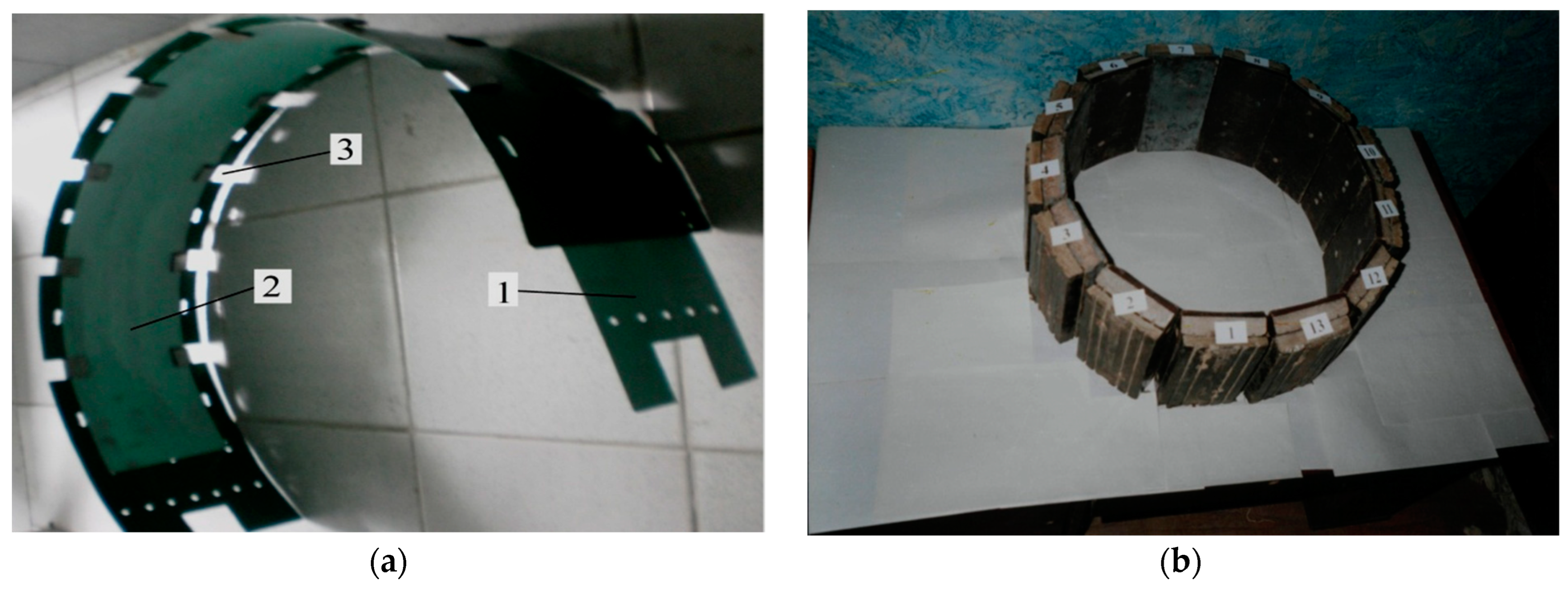
The model band brake includes a combined brake band (Figure 2), the inner (working) surface of which interacts with the outer surfaces of the tire at the first stage of braking [108]. The inner (working) surfaces of the friction pads were placed with tension on the working surface of the steel brake pulley with the help of connecting elements.
Figure 3 shows the general view of the friction assemblies installed on the brake pulley of the band brake.
Testing of the friction units of the band brake on the drawworks was carried out as follows. The material of the brake friction pads (120 × 230 × 20 mm) was selected and their linear dimensions were measured with a caliper with an accuracy of ±0.05 mm and weighed on a scale with an accuracy of ±0.5 g before tribological tests were conducted. After that, the brake friction pads were mounted on the brake tape, which, together with a set of these pads, was installed on the stand, embracing the brake pulley mounted on the bearing supports. The power of the electric motor was turned on and a load was applied to the brake band, according to the test program, to ensure the creation of the necessary contact pressure on the working friction surface of the brake.
Testing of the brake pads was carried out in the following modes. The brake steel tape had a girth angle β = 270° of the brake pulley on the outer surfaces of the friction linings. Loads of 400, 500, 600, 700 and 800 N were applied to the overlapping branch of the brake tape. The braking pressure was from 15 to 5 MPa, depending on the tension of the brake tape and the number of the brake pad. The numbers of revolutions of the brake pulley were 50, 100, 150 and 200 rpm. Braking was carried out until the brake pulley came to a complete stop, and it remained braked for 60 s. After that, the load was removed from the coincident branch of the brake belt, and when the brake pulley reached the specified number of revolutions, the next braking was performed after 30 s. The numbers of braking cycles were 25, 50, 75, 100, 125 and 150.
Temperature measurements in the friction contact zone of the brake were carried out with an automatic electronic potentiometer of accuracy class 0.5 equipped with a chromel-copel (E) thermocouple of the ChK type. To complete the tribological tests, the power to the electric motor was turned off, the load was removed from the brake belt and the brake friction pads were dismantled. Brake friction pads were weighed again and the amount of their linear wear was measured. In addition, the formation of cracks on the working surface of the brake friction pads and brake pulleys on the stand and in the operating conditions of drilling equipment for the National joint-stock company “Naftogaz of Ukraine” was investigated.
The authors examined a large number of worn brake pads and brake pulleys of belt brakes of drilling winches. This article presents the most typical variants of the propagation of a web of cracks on the inner concave cylindrical worn friction surface of brake pads and cracks on the outer convex cylindrical surface of steel brake pulleys. To ensure the reliability of the results of macroscopic studies, the friction surface of the worn brake pads was not additionally mechanically processed, but only delicately cleaned of contamination with a soft brush made of natural wool, washed with ethyl alcohol and dried in the air.
The friction surface of the worn steel brake pulleys was also not additionally processed. After the wear tests were completed, SEM and EDXS tests were performed on 10 × 10 mm cross-sectional samples of the worn surface of the brake friction pads, which were cut with a mechanical saw. Microscopic studies were conducted at the center for collective use of scientific instruments “Center for Electron Microscopy and X-ray Microanalysis” of the Karpenko Physico-mechanical Institute of the National Academy of Sciences of Ukraine, Lviv. The examined surface of the worn brake pad was not additionally processed, but only delicately cleaned of contamination with a soft brush made of natural wool, washed with ethyl alcohol and dried in the air. Before conducting electron microscopic studies, a monolayer of gold was applied to the friction surface of the samples to increase electrical conductivity using a magnetron type JFC-1600 (JEOL, Tokyo, Japan). We used a ZEISS EVO 40XVP (ZEISS Group, Jena, Germany) scanning electron microscope with a micro-X-ray spectral analysis system and an INCA ENERGY 350 (Oxford Instruments, Abingdon, UK) energy-dispersive X-ray spectrometer.
The worn surface of the friction pads was also investigated by image processing.

2.3. Image Acquisition and Geometric Transformation

Reliable image processing and analysis of brake pad surfaces require the acquisition of suitable input images. There are two main difficulties to be dealt with in order to obtain input images suitable for further processing. The first obstacle is related to the fact that after operation the surface of the brake pad becomes “polished” and thus, under certain angles of view, causes glares on the surface. Such glares, depending on their severity, make image processing very difficult to impossible in terms of providing the expected level of reliability for further analysis. Unfortunately, the nature of the brake pad surface allows its cracks to be clearly visible only from certain angles of view and light. The second obstacle arises from the fact that the operating brake pad surface possesses a circular curvature of 0.7 m. This curvature also creates additional complications to the glare problem by narrowing the angles from which the brake pad surface picture can be taken correctly.
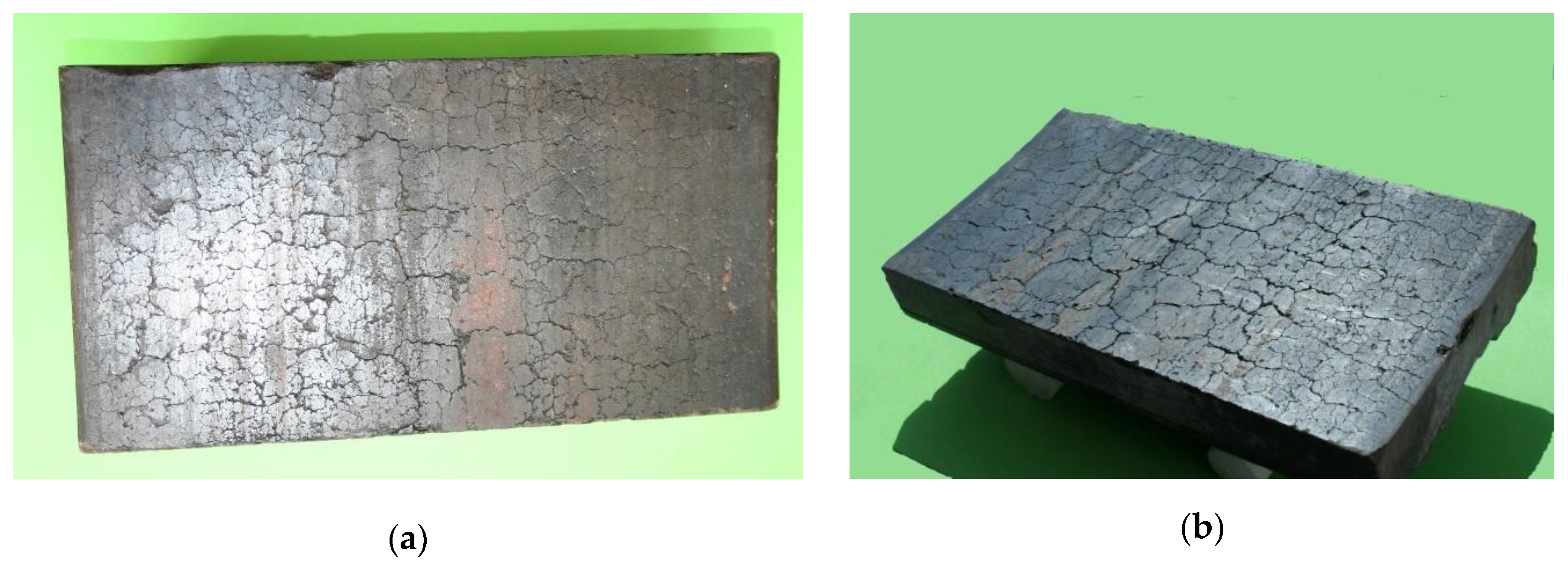
As a result, a suitable picture of the brake pad surface can only be taken from a certain angle. Examples of images of the brake pad surface taken perpendicularly to its surface and taken from an angle that allows us to avoid glares are shown in Figure 4.
As one can see from Figure 4b, the brake pad surface is presented in the image at a certain perspective due to the angle of view. At this point, it is necessary to perform mapping of the brake pad surface to the regular grid of the rectangular image. For this purpose, we form a regular grid on the surface of a cylinder and perform mapping from the obtained image to the surface of the cylinder.
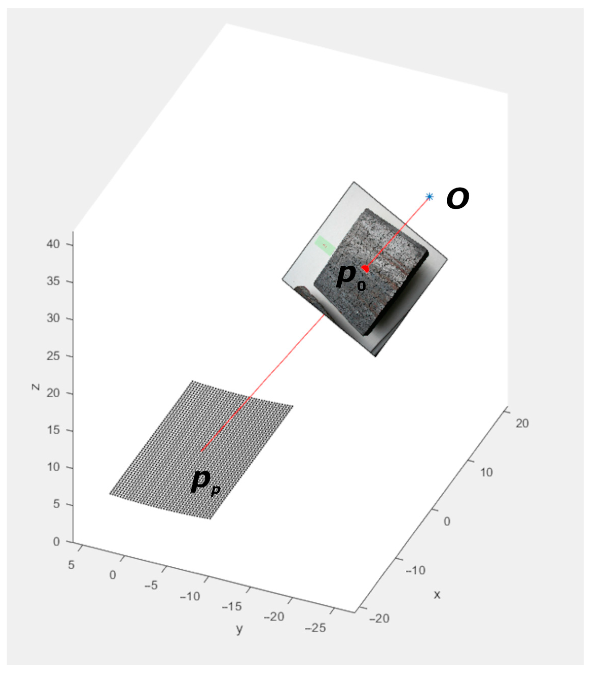
The part of a cylinder occupied by the regular image grid is determined by the brake pad surface dimensions (120 × 230 mm) and the radius of its circular curvature of 0.7 m. To recover the image of the brake pad, every pixel I c x , y of the rectangular grid on the surface of the cylinder is assigned with the value of the original image I o u , v . To perform this assignment, the mapping from u , v to x , y should be established. The coordinates u , v are determined by the intersection of the line S with the camera image plane M . Line S passes through the point of the rectangular grid on the surface of the cylinder p p = x , y , z and optical center O of the camera and is determined by the equation p p = O + t m , where m = O p p / O p p . Image plane M is determined by the equation p p 0 , n = 0 , where p 0 is a point of intersection of image plane M with the main optical axis of the camera, n = O p 0 / O p 0 is the normal vector to the image plane, the direction of which coincides with the main optical axis, and   ,   is the scalar product. The intersection point p is determined by the parameter t i :
t i = p p 0 , n / m , n ,
thus, p = O + t i m .
To determine the coordinates u , v for a given p , the following equation is used:
u , v , w = R 1 ( p p 0 ) ,
where R is the camera rotation matrix, and w = 0 .
The schematic formation of a brake pad image is shown in Figure 5.

2.4. Image Processing

The goal of the further image processing and analysis tasks consists in finding the integral characteristic of the brake pad surface sensitive to the operation time. The surface cracks were chosen as among the distinct features of the used brake pad. Thus, the aim of the image processing stage is to detect cracks on the surface of the brake pad. For this purpose, the scale-space theory framework was used. This allows us to build a scale-invariant image processing method, which is useful for our particular task as the given brake pad cracks have a wide range of widths. The scale-space approach suggests the input gray-scale image I x , y is presented with its scale-space representation L x , y , σ as defined by
L x , y , σ = g x , y , σ I ,
where g x , y , σ = 1 2 π σ e x 2 + y 2 2 σ   , t is the scale parameter and ∗ denotes the convolution operator.
More general than the convolution operator is the Hadamard composition [110] or, in general, any composition of functions [111].
The crack detection was based on the computation of the measure L c , as suggested in [112].
L c = L x x + L y y L x x + L y y 2 + 4 L 2 x y ,
where L x x , L y y and L x y denote derivatives of L x , y , σ along its respective axes. Measure L c represents the crack strength and is computed for different values of scale parameter t . The values of the parameter t depend on the size of objects we try to detect in the input image, and thus can be used to tune the sensitivity of the crack detector.
To obtain a final binary image with detected cracks, the values of L c should be properly thresholded. In practice, the constant threshold value results in significant error in the final binary picture of detected cracks. This is explained by the different values of L c produced by cracks in images of different brake pads, which thus require different threshold values for correct segmentation. Therefore, it is necessary to use techniques with adaptive threshold values. For this purpose, the Otsu method [113] was used.
The next stage is the analysis of the binary image of the segmented cracks, which consists of finding an integral characteristic of the brake pad surface that would be able to reflect the intensity with which the brake pad is operated. To calculate these integral characteristics, the additional steps of contour detection and skeletonization of the image should be performed.
The results of contour detection and skeletonization are used for crack parameter estimation. Therefore, after the segmentation procedure, three parameters were calculated:
The ratio of the area of segmented cracks to the total area
P 1 = S c r S t o t ,
where S c r is the area of segmented cracks and S t o t is the total area of the image;
The ratio of the perimeter of segmented cracks to the total area
P 2 = P c r S t o t ,
where P c r is the perimeter of the segmented cracks;
The ratio of the skeletonized cracks to the total area
P 3 = S s c e l S t o t .
These parameters are the integral characteristics of the brake pad friction surface which are sensitive to the operation time and can serve as an estimate of the degree of wear of a given surface.

3. Results and Discussion

3.1. Study of the Drilling Drawwork Brake Wear

The drilling drawwork is equipped with band brakes (Figure 1, Figure 2 and Figure 3), which brake the lifting drum on which the steel rope is wound during lowering into the well and raising of the drilling tool or pipe casing from the well, stopping the drilling (casing) and holding it stationary. It is used on pipe columns, as well as when feeding the tool to the wellbore in the process of rotary and turbine drilling in the absence of an automatic bit feeding regulator. In addition, the drawwork serves to transmit power to the rotor, and raise and lower the drilling tower, respectively, during its installation or dismantling after the completion of the construction of the well.
The band brakes are used as the main part of the drilling drawwork. Thede brakes are usually installed on high-speed shafts that transmit the smallest torques. This makes it possible to reduce the overall dimensions of the band brake while simultaneously providing the required amount of braking torque.
In the band brakes, the working element is a flexible steel band with polymer friction pads attached to it, which during braking are pressed against the outer cylindrical surface of the brake pulley due to the angular movement of the moving end of the specified band. During the lowering/raising of drilling tools, almost all of the kinetic energy is transformed into thermal energy during the braking process, which leads to intensive heating of the surface layers of the friction pads and the metal pulley.
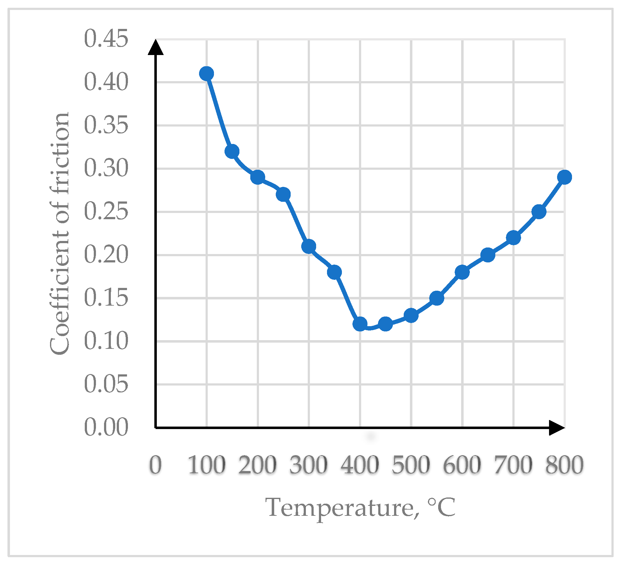
For the reliable operation of the belt brake, it is important to ensure a stable value of the coefficient of friction in the metal–polymer pair during braking in a wide temperature range. According to Interstate Standard GOST 10851–94 [105], FK-24A friction material is recommended for use in friction nodes paired with alloy steel under the following operating conditions: friction surface temperature up to 700 °C, sliding speed 10 m/s; pressure 1.5 MPa. Therefore, the effect of the temperature in the friction zone during braking on the value of the friction coefficient was investigated on the modernized stand (Figure 6).
The analysis of the graphical dependence presented in Figure 6 shows that with increasing temperature in the friction zone, the value of the friction coefficient initially decreases and reaches a minimum value of 0.12 at temperatures of 400–470 °C. Under such temperature conditions, the decomposition products of the bond (phenol–formaldehyde resin) act as a solid lubricant. A further increase in the temperature in the friction zone leads to a certain increase in the value of the coefficient of friction, but it no longer reaches a higher value than at the beginning of the test at a temperature of 100 °C. During friction, phenol–formaldehyde resin decomposes under the influence of elevated temperature, providing the necessary positive gradient of mechanical properties in a tribological pair with alloy steel. FK-24A material exhibits high frictional properties during difficult operating conditions of the belt brake of the drilling drawwork. Similar dependences for the change in the friction coefficient on temperature during the operation of retinax in a pair with 40ChN steel were presented in Interstate Standard GOST 10851–94 [105], where the minimum value of the friction coefficient was also observed in the temperature range from 400 to 500 °C.
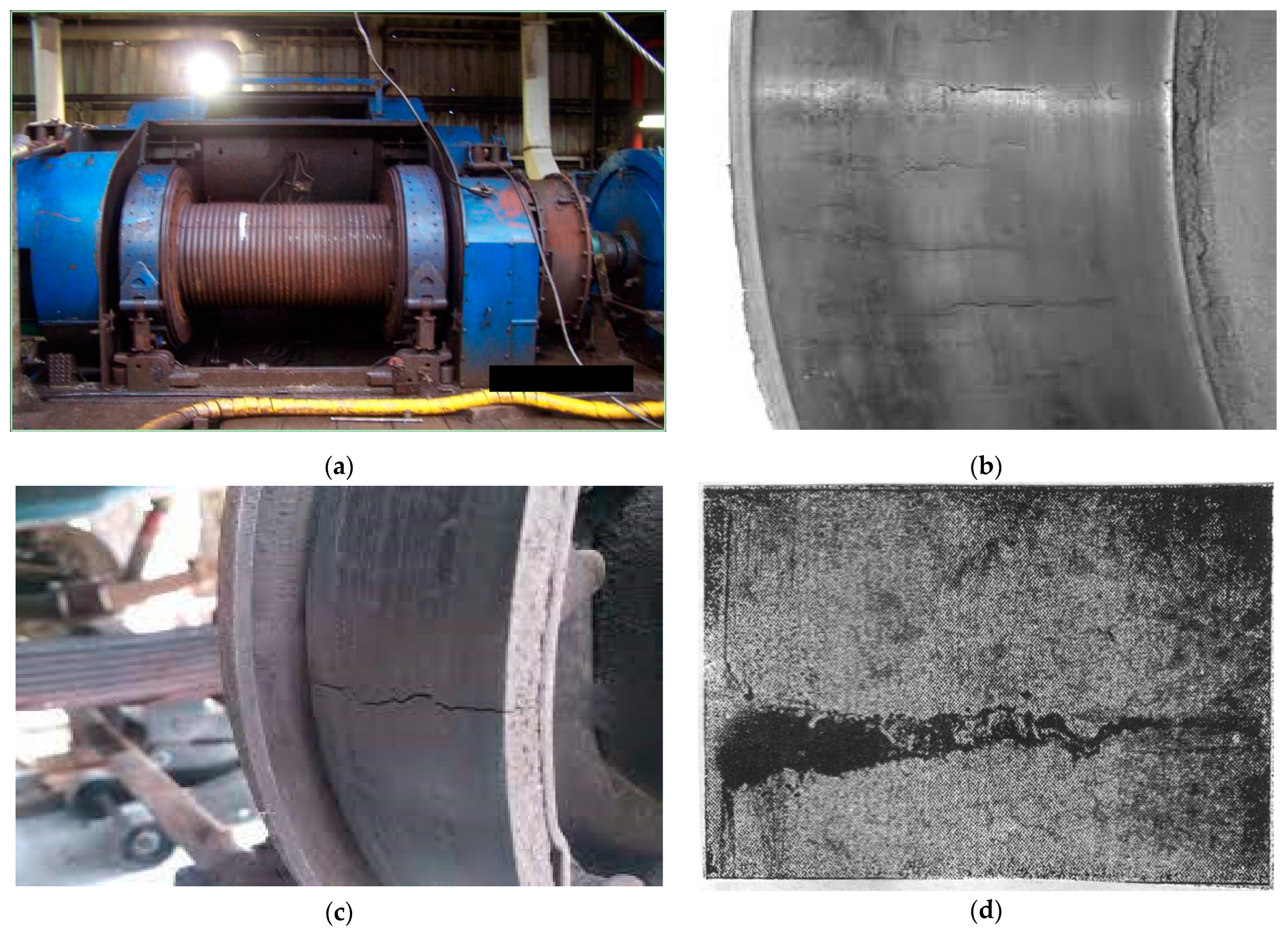
It should be noted that the process of converting the mechanical energy of the moving heavy column of drill pipes into thermal energy takes place in the belt brake of the drill drawwork. This phenomenon leads to intense heating of the surface layers of the friction pads and the brake pulley, and leads force factors to their deformation during friction. At the same time, the maximum values of temperature and mechanical stresses are reached in the friction zone, which leads to the destruction of the materials of the friction pair. In particular, during the destruction of the FK-24A material, hydrogen is released from its bond—phenol–formaldehyde resin [–C6H3(OH)–CH2–]n. Hydrogen atoms have a fairly small atomic radius, so they penetrate easily deep into the pulley, causing flooding of the steel and its embrittlement. All these factors taken together lead to the intensification of the processes of wear and destruction of brake parts not only due to the mechanical interaction of friction surfaces, but also due to the hydrogen embrittlement of steel (Figure 7).
In the process of long-term operation of drill drawworks (Figure 7a), a large number of braking cycles occur when the drill pipe column is built up during the lowering of the tool into the well or the unscrewing of the drill pipe plugs during the removal of the tool from the well, which leads to cyclic heating/cooling of the brake and the appearance of low-cycle crack fatigue on the working surfaces of brake metal pulleys and friction polymer pads. Cracks are mostly formed on the convex cylindrical friction surface of the metal pulley, which are directed along its longitudinal axis and do not cross each other (Figure 7b). It should be noted that in some cases, a main through crack was formed in the rim of the metal pulley (Figure 7c,d).
Wang et al. [114] found a modified microstructure consisting of a white etching layer containing nanosized ferrite on the friction surface of worn brake discs. Hurey et al. [115] showed the protective properties of a nanocrystalline reinforced layer during fretting wear. In studies [54,116], the temperature and force conditions for the formation of white layers on steel and cast iron were determined. It should be noted that the results of research [117,118] indicate that such nanostructures can serve as a barrier for the penetration of hydrogen into steel. Mechanisms of initiation and propagation of cracks in metals under high-temperature loads were developed by researchers [119,120], and the influence of hydrogen on the properties of metals in various environments was discussed in detail in papers [121,122,123].
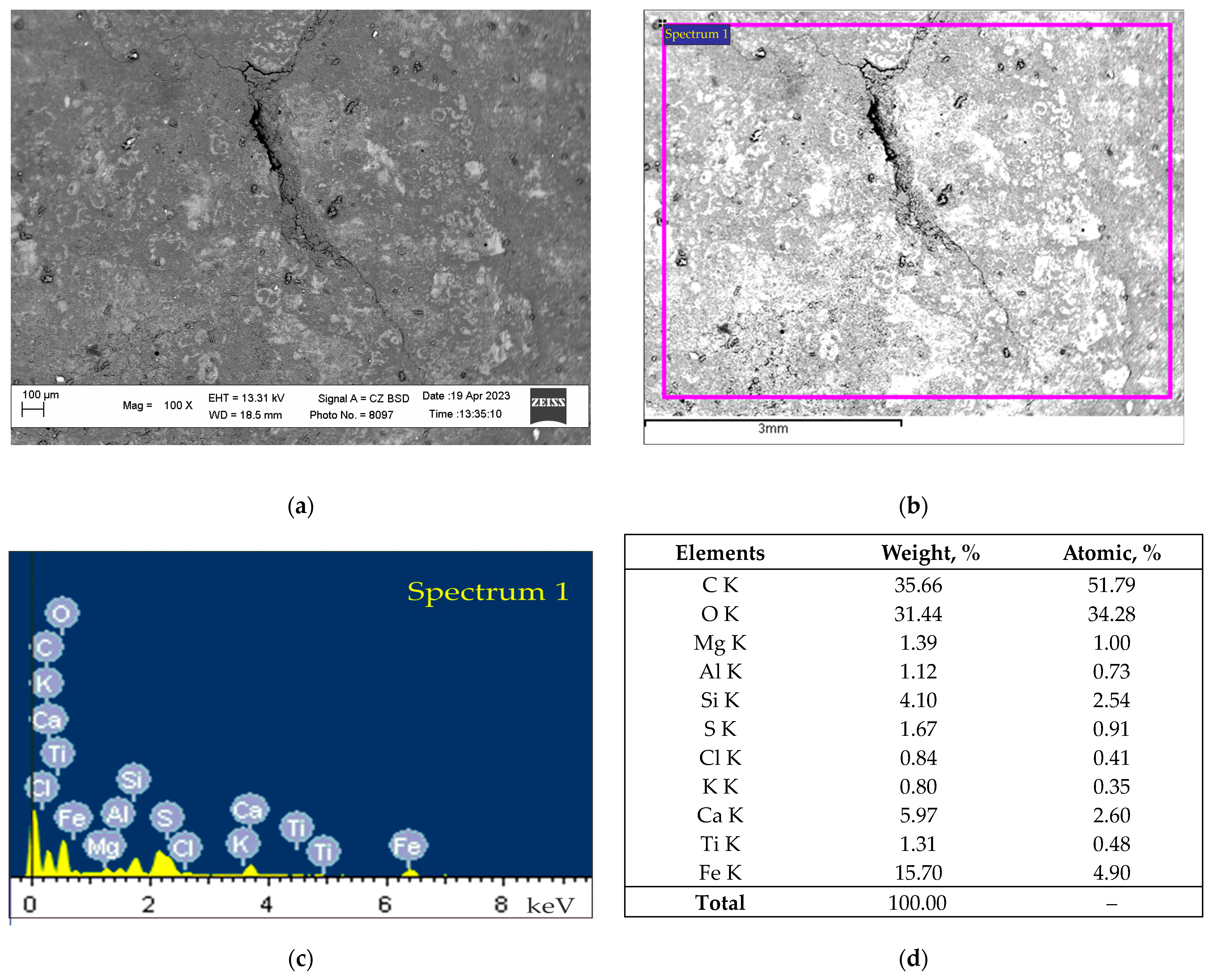
At the same time, an ensemble of branched, arbitrarily oriented surface cracks is formed on the concave cylindrical friction surface of the friction pads, which intersect each other, forming closed polyhedra (Figure 4). We investigated the composition of the polymer friction material FK-24A of brake friction pads on the friction surface in a worn state without cracks (Figure 8) and in a worn state with cracks (Figure 9).
We found that at the stage of running-in of the brake pad in the friction zone with the steel pulley, the presence of all the main components of the retinax FK-24A friction material and a small percentage of iron (0.69%) can be observed (Figure 8d).
It should be noted that at the stage of wear of the brake pad and the formation of cracks on the surface in the friction zone with the steel pulley, the presence of all the main components of the retinax FK-24A friction material, as well as increased iron content of up to 15.70%, is observed (Figure 9d). This phenomenon can be explained by the increased wear of the flooded and brittle metal of the steel pulley and the accumulation of wear products in the cracks and pores of the brake pad.
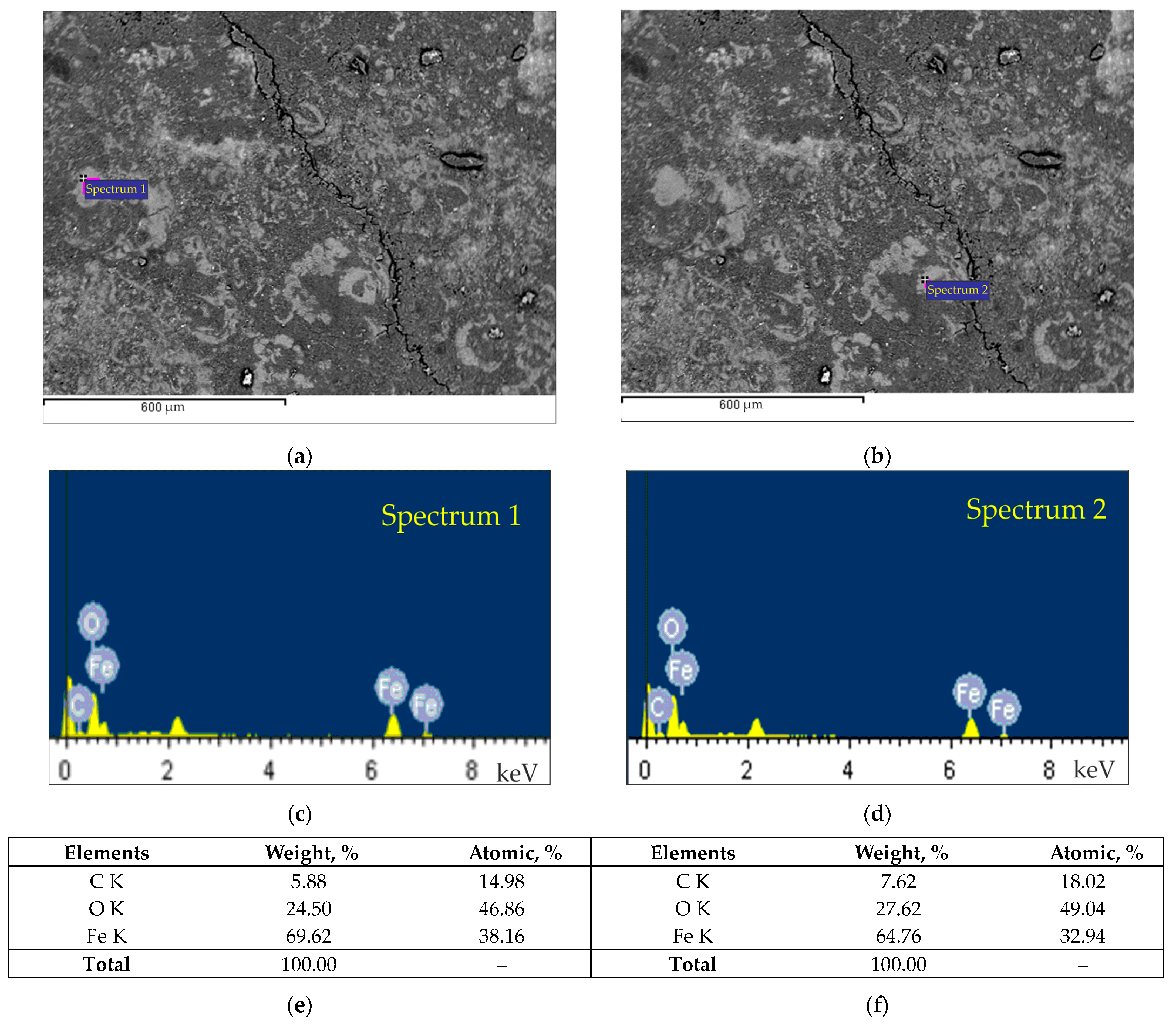
The composition of the polymer friction material FK-24A on the friction surface of the brake pad in a worn state with cracks was also studied in detail (Figure 10).
Experiments were carried out on areas of the surface that were located at different distances from the crack (Figure 10a,b). It was established that the area farther from the crack had increased iron content—69.62% (Figure 10c,e)—and the area near the crack had a lower iron content—64.76% (Figure 10d,f). Such a difference in the amount of wrought iron in the friction surface of the brake pad at different distances from the crack may be due to the fact that part of the wear products accumulates in this crack. This representation of the images was due to our desire to investigate local areas of the worn friction surface of the brake pads (Figure 8 and Figure 9), in particular at different distances from the cracks (Figure 10).
In Figure 11, the character of the worn surface of the area of interest of the brake pad is shown, along with the mapping of the redistribution of the elements after the friction tests.
The analysis of the EDS maps (Figure 11b–i) shows that C, O, Ca, Ba and Fe are located in the same regions, indicating the existence of complex compounds, while Si is mainly observed in the friction surface defects. The redistribution of Mn and Cr is relatively uniform, showing transfer from the steel counterbody.

3.2. Results of Image Processing of the Worn Surface

This section demonstrates the results of the practical application of the above-described methodology of image processing of worn brake pads.
The first step consists in input image acquisition and its geometric transformation with the purpose of obtaining a transformed image suitable for further processing and is described in Section 2.1. Figure 12 shows the results of mapping of the obtained image of the brake pad friction surface on the surface of a cylinder using image transformation, represented by Equations (1) and (2): Figure 12a is the obtained image and Figure 12b is the restored image of the surface of a brake pad.
After that, the image processing step is applied in order to detect cracks at the friction surface of a brake pad. For this purpose, the restored input image is presented in the scale-space representation (3), and the crack strength measure L c (4) is computed. The visualization of measure L c (4) calculated for the input image in Figure 13a is shown in Figure 13b. Segmentation of the transformed (Figure 13a) and preprocessed (Figure 13b) images with the Otsu method is presented in Figure 13c and Figure 13d, respectively. As can be concluded from the images in Figure 13c,d, the scale-space-invariant approach is of great importance since direct segmentation without this step gives an unsatisfactory result with a high percentage of oversegmentation.
The results of the contour detection and skeletonization steps for the image in Figure 13d are presented in Figure 14a,b.
Parameters P 1 ,   P 2 ,     P 3 , which are the integral characteristics of the degree of wear of the brake pad friction surface, are given in Table 4 for the different brake pads, arranged in ascending order of their operating time.
The results of the calculations show an increase in the percentage of integral characteristics of brake pad friction surfaces during operation. They confirm the possibility of using such characteristics as an indicator of the degree of wear of the brake pad.
Convolutional neural networks can be used for evaluating the degradation of the brake pad friction surface during its operation. They require a large dataset for training. Image areas of a typical size of 256 × 256 pixels can be selected from input images. The dataset size can be increased by flipping and rotating operations as well as image simulation.
It should be noted that the disadvantage of asbestos-containing friction materials is their low destruction temperature and their reactivity in interacting with steel/cast iron, which causes them to form brittle carbides and supersaturated solid solutions. In addition, asbestos is harmful to the health of staff. Degradation of polymer materials on a resin bond under the influence of various factors is described in paper [124]. Researchers [125,126] conducted an analysis of brake wear products and indicated their harmful effects, in particular connected with brake wear particle emissions [127,128,129,130,131], on human health and the environment and proposed measures to reduce them.
The task of researching the wear of brake pads in various fields of application [132,133,134,135] is relevant and requires further study, in particular regarding the use of other materials [136,137,138] and the investigation of their wear.
The parameters of the amount of wear of brake pads and brake pulleys are regulated by normative documents for the operation of brakes of drilling winches. In practice, during the operation of belt brakes of drilling winches, it is difficult to directly monitor the condition of the friction surfaces of brake pads, since there is no direct access to them, but only their amount of linear wear and the reliability of their mechanical attachment to steel tape can be controlled. When the minimum permissible thickness of the brake pads is reached, which is usually about 10 mm (for the maximum amount of linear wear), a decision is made to replace them with new ones.
In addition, the condition of the working outer cylindrical convex friction surface of the steel brake pulley, which has direct access, is also monitored. If the linear wear of the brake pulley is more than 10 mm per side (with the maximum reduction in diameter) and/or if there are cracks on its working cylindrical surface with a length of more than 80 mm and a width of 0.2 to 0.5 mm, it is immediately replaced with a new one.
The results of macroscopic analysis (image processing) of the worn friction surface of brake pads demonstrate the nature of crack propagation and can complement the understanding of the wear mechanism of brake friction pair elements on a microscale. In particular, this article shows the micro-level distribution of chemical elements of the material of the steel brake pulley relative to thermal cracks formed on the worn friction surface of the polymer brake pad (Figure 10), as well as the distribution of chemical elements on the worn friction surface of the brake pad (Figure 11).
The method of image processing developed by us for the concave friction surface of brake pads is advised to be used both during the development of optimal compositions of new composite materials for brake pads and to substantiate the choice of rational modes of operation of friction pairs of brakes of various types and designs.
In further studies, it is planned to establish the influence of the step of the location of brake friction pads made of asbestos-free material on the brake belt of the drill winch on the nature of the destruction of friction surfaces.

4. Conclusions

Based on the results of laboratory and industrial research, the following was established:
  • The minimum value of the coefficient of friction (0.12) for band brakes equipped with retinax pads is achieved at temperatures on the friction surface of 400–470 °C. At this temperature, the decomposition products of the bond (phenol–formaldehyde resin) act as an effective solid lubricant;
  • Thermal fatigue cracks appear on the working surface of the brake metal pulleys, which are directed along its longitudinal axis and do not cross each other;
  • Thermal fatigue cracks are formed on the worn working surface of non-metallic friction pads, which cross each other, forming separate islands, which is associated with both thermal destruction and shrinkage of the retinax. An uneven distribution of iron at different distances from the crack was revealed;
  • A method for estimation of the degree of the degradation of the brake pad based on processing of their surface images was developed. This method consists of acquisition of a suitable input image taken from particular angle that allows us to avoid glares, mapping of the obtained image on the surface of a cylinder to cope with perspective distortion which appears due to the angle of view, application of the scale-space theory for crack detection with further contour detection and skeletonization and finding the integral characteristics of the brake pad surface which reflect the intensity with which the brake pad was operated. It was shown that such characteristics as the ratio of the area of segmented cracks to the total area, the ratio of the perimeter of segmented cracks to the total area and the ratio of the skeletonized cracks to the total area are good indicators of the degree of brake pad degradation during operation;
  • The proposed taxonomy of images can be used both during the development of component compositions of new friction materials for brake pads, and during research into the performance of commercial materials during the justification of rational choices in the operating modes of brakes.

Author Contributions

Conceptualization, R.V., T.M. and L.R.; methodology, T.M., R.V., I.I., O.B. and S.K.; software, T.M.; validation, T.M., R.V., I.I., O.B. and M.B.; formal analysis, T.M., R.V., I.I. and O.B.; investigation, T.M., S.K. and L.R.; resources, R.V., S.K. and L.R.; data curation, I.I., S.K. and L.R.; writing—original draft preparation, T.M., R.V., I.I., O.B., S.K. and L.R.; writing—review and editing, T.M., R.V., M.B. and L.R.; visualization, T.M., R.V., I.I., O.B., S.K. and L.R.; supervision, T.M., I.I. and L.R.; project administration, R.V., M.B. and L.R.; funding acquisition, R.V., M.B. and L.R. All authors have read and agreed to the published version of the manuscript.

Funding

This research was funded by the National Academy of Sciences of Ukraine under grant number 0122U002136. This research was funded by the Ministry of Science and Education of Ukraine for the grant to implement projects 0123U101858 and 0124U000668.

Data Availability Statement

The data are contained within this article.

Acknowledgments

The authors express their sincere gratitude and respect to the Armed Forces of Ukraine, who made it possible to complete the preparation of this article for publication. The authors thank the team of the Center for collective use of scientific instruments “Center for Electron Microscopy and X-ray Microanalysis” of the Karpenko Physico-mechanical Institute, National Academy of Sciences of Ukraine, Lviv for promptly conducting microscopic studies of worn brake pads. The team of authors express their gratitude to the reviewers and academic editor for valuable recommendations that have been taken into account to significantly improve the quality of this paper.

Conflicts of Interest

The authors declare no conflicts of interest.

References

  1. Andrusiv, U.; Zelinska, H.; Galtsova, O.; Kupalova, H.; Goncharenk, N. The modeling and forecasting of fuel and energy resources usage in the context of the energy independence of Ukraine. Polityka Energetyczna 2021, 24, 29–47. [Google Scholar] [CrossRef]
  2. Kondrat, O.; Lukin, O.; Smolovyk, L. Analysis of possibilities to increase oil recovery with the use of nitrogen in the context of deep oil deposits of the dnipro-donetsk oil-and-gas Ukrainian province. Min. Miner. Depos. 2019, 13, 107–113. [Google Scholar] [CrossRef]
  3. Adeosun, O.; Anagreh, S.; Tabash, M.; Adedokun, A. Revisiting the connectedness between oil prices and uncertainty indicators in BRICS countries. Resour. Policy 2023, 86, 104278. [Google Scholar] [CrossRef]
  4. Al-Rbeawi, S. A Review of Modern Approaches of Digitalization in Oil and Gas Industry. Upstream Oil Gas. Technol. 2023, 11, 100098. [Google Scholar] [CrossRef]
  5. Zang, C.; Lu, Z.; Ye, S.; Xu, X.; Xi, C.; Song, X.; Guo, Y.; Pan, T. Drilling Parameters Optimization for Horizontal Wells Based on a Multiobjective Genetic Algorithm to Improve the Rate of Penetration and Reduce Drill String Drag. Appl. Sci. 2022, 12, 11704. [Google Scholar] [CrossRef]
  6. Chen, X.; Du, X.; Weng, C.; Yang, J.; Gao, D.; Su, D.; Wang, G. A real-time drilling parameters optimization method for offshore large-scale cluster extended reach drilling based on intelligent optimization algorithm and machine learning. Ocean Eng. 2024, 291, 116375. [Google Scholar] [CrossRef]
  7. Bembenek, M.; Grydzhuk, Y.; Gajdzik, B.; Ropyak, L.; Pashechko, M.; Slabyi, O.; Al-Tanakchi, A.; Pryhorovska, T. An Analytical–Numerical Model for Determining “Drill String–Wellbore” Frictional Interaction Forces. Energies 2024, 17, 301. [Google Scholar] [CrossRef]
  8. Peng, S.; Huang, Z.; Wang, M.; Xiong, C.; Chen, K. Study on the Influence of Surface Texture Parameters of Oil Production Screw Motor Rotor on the Tribological Properties of Its Friction Pair. Processes 2023, 11, 618. [Google Scholar] [CrossRef]
  9. Shats’kyi, I.P.; Shopa, V.M.; Velychkovych, A.S. Development of full-strength elastic element section with open shell. Strength Mater. 2021, 53, 277–282. [Google Scholar] [CrossRef]
  10. Prysyazhnyuk, P.; Molenda, M.; Romanyshyn, T.; Ropyak, L.; Romanyshyn, L.; Vytvytskyi, V. Development of a hardbanding material for drill pipes based on high-manganese steel reinforced with complex carbides. Acta Montan. Slovaca 2022, 27, 685–696. [Google Scholar] [CrossRef]
  11. Ropyak, L.; Shihab, T.; Velychkovych, A.; Bilinskyi, V.; Malinin, V.; Romaniv, M. Optimization of Plasma Electrolytic Oxidation Technological Parameters of Deformed Aluminum Alloy D16T in Flowing Electrolyte. Ceramics 2023, 6, 146–167. [Google Scholar] [CrossRef]
  12. Kotsyubynsky, V.; Shyyko, L.; Shihab, T.; Prysyazhnyuk, P.; Aulin, V.; Boichuk, V. Multilayered MoS2/C nanospheres as high performance additives to lubricating oils. Mater. Today Proc. 2019, 35, 538–541. [Google Scholar] [CrossRef]
  13. Gaponova, O.P.; Antoszewski, B.; Tarelnyk, V.B.; Kurp, P.; Myslyvchenko, O.M.; Tarelnyk, N.V. Analysis of the quality of sulfomolybdenum coatings obtained by electrospark alloying methods. Materials 2021, 14, 6332. [Google Scholar] [CrossRef] [PubMed]
  14. Drach, I.; Goroshko, A.; Dwornicka, R. Design Principles of Horizontal Drum Machines with Low Vibration. Adv. Sci. Technol. Res. J. 2021, 15, 258–268. [Google Scholar] [CrossRef] [PubMed]
  15. Royzman, V.; Drach, I.; Bubulis, A. Movement of Working Fluid in the Field of Centrifugal Forcesand Forcesof Weight. In Proceedings of the 21st International Scientific Conference, Kaunas, Lithuania, 12–13 May 2016; pp. 222–224. [Google Scholar]
  16. Velichkovich, A.S.; Dalyak, T.M. Assessment of stressed state and performance characteristics of jacketed spring with a cut for drill shock absorber. Chem. Pet. Eng. 2015, 51, 188–193. [Google Scholar] [CrossRef]
  17. Moisyshyn, V.M.; Slabyi, O.O. Creation of the vibroprotective device for adjustment of dynamics of a column of steel drill pipes and a bit. Металлофизика И Новейшие Технологии 2018, 40, 541–550. [Google Scholar] [CrossRef]
  18. Dutkiewicz, M.; Velychkovych, A.; Shatskyi, I.; Shopa, V. Efficient Model of the Interaction of Elastomeric Filler with an Open Shell and a Chrome-Plated Shaft in a Dry Friction Damper. Materials 2022, 15, 4671. [Google Scholar] [CrossRef]
  19. Wang, C.; Chen, W.; Wu, Z.; Li, J.; Liu, G. Stick–Slip Characteristics of Drill Strings and the Related Drilling Parameters Optimization. Processes 2023, 11, 2783. [Google Scholar] [CrossRef]
  20. Pryhorovska, T.O.; Chaplinskiy, S.S.; Kudriavtsev, I.O. Finite element modelling of rock mass cutting by cutters for PDC drill bits. Shiyou Kantan Yu Kaifa/Pet. Explor. Dev. 2015, 42, 812–816. [Google Scholar] [CrossRef]
  21. Chudyk, I.I.; Femiak, Y.M.; Orynchak, M.I.; Sudakov, A.K.; Riznychuk, A.I. New methods for preventing crumbling and collapse of the borehole walls. Nauk. Visnyk Natsionalnoho Hirnychoho Universytetu 2021, 2021, 17–22. [Google Scholar] [CrossRef]
  22. Moisyshyn, V.; Voyevidko, I.; Tokaruk, V. Design of bottom hole assemblies with two rock cutting tools for drilling wells of large diameter. Min. Miner. Depos. 2020, 14, 128–133. [Google Scholar] [CrossRef]
  23. Grydzhuk, J.; Chudyk, I.; Velychkovych, A.; Andrusyak, A. Analytical estimation of inertial properties of the curved rotating section in a drill string. East. Eur. J. Enterp. Technol. 2019, 1, 6–14. [Google Scholar] [CrossRef]
  24. Goryk, O.; Buchynskyi, A.; Romanyshyn, L.; Nurkusheva, S.; Bembenek, M. Evaluation of the State of Innovative Activity of Machine-Building Enterprise. Manag. Syst. Prod. Eng. 2024, 32, 1–11. [Google Scholar] [CrossRef]
  25. Pavković, D.; Cipek, M.; Krznar, M.; Benić, J. A retrofitting control system design suitable for deep borehole drilling using legacy draw-works mechanical brake hardware. Energy Convers. Manag. 2022, 260, 115589. [Google Scholar] [CrossRef]
  26. Seo, H.; Lee, D.G.; Park, J.; Song, W.; Lee, J.J.; Sohn, S.S.; Jang, H. Quench hardening effect of gray iron brake discs on particulate matter emission. Wear 2023, 523, 204781. [Google Scholar] [CrossRef]
  27. Barros, L.; Poletto, J.; Buneder, D.; Neis, P.; Ferreira, N.; Pavlak, R.; Matozo, L. Effect of pressure in the transition between moderate and severe wear regimes in brake friction materials. Wear 2019, 438–439, 203112. [Google Scholar] [CrossRef]
  28. Yanar, H.; Purcek, G.; Ayar, H.H. Effect of steel fiber addition on the mechanical and tribological behavior of the composite brake pad materials. IOP Conf. Ser. Mater. Sci. Eng. 2020, 724, 012018. [Google Scholar] [CrossRef]
  29. Zhang, P.; Zhang, L.; Wei, D.; Wu, P.; Cao, J.; Shijia, C.; Qu, X. A high-performance copper-based brake pad for high-speed railway trains and its surface substance evolution and wear mechanism at high temperature. Wear 2020, 444–445, 203182. [Google Scholar] [CrossRef]
  30. Tatsii, R.M.; Stasyuk, M.F.; Pazen, O.Y. Direct Method of Calculating Nonstationary Temperature Fields in Bodies of Basic Geometric Shapes. J. Eng. Phys. Thermophys. 2021, 94, 298–310. [Google Scholar] [CrossRef]
  31. Tatsiy, R.M.; Pazen, O.Y.; Vovk, S.Y.; Kharyshyn, D.V. Direct method of studying heat exchange in multilayered bodies of basic geometric forms with imperfect heat contact. Nauk. Visnyk Natsionalnoho Hirnychoho Universytetu 2021, 2021, 60–67. [Google Scholar] [CrossRef]
  32. Malanchuk, N.I.; Slobodyan, B.S.; Martynyak, R.M. Friction sliding of elastic bodies in the presence of subsurface inclusions. Mater. Sci. 2017, 52, 819–826. [Google Scholar] [CrossRef]
  33. Tatsiy, R.M.; Pazen, O.Y.; Vovk, S.Y.; Kharyshyn, D.V. Simulation of heat transfer process in a multilateral cylindrical shell taking into account the internal heat sources. Nauk. Visnyk Natsionalnoho Hirnychoho Universytetu 2020, 2020, 27–32. [Google Scholar] [CrossRef]
  34. Belhocine, A.; Wan Omar, W.Z. Computational fluid dynamics (CFD) analysis and numerical aerodynamic investigations of automotive disc brake rotor. Aust. J. Mech. Eng. 2018, 16, 188–205. [Google Scholar] [CrossRef]
  35. Wang, D.; Wang, R.; Zhang, J. Dynamic brake characteristics of disc brake during emergency braking of the kilometer deep coal mine hoist. Adv. Mech. Eng. 2020, 12, 1–23. [Google Scholar] [CrossRef]
  36. Zhang, S.; Yin, J.; Liu, Y.; Liu, N.; Sha, Z.; Wang, Y.; Rolfe, B. Thermal–structural coupling analysis of brake friction pair based on the displacement gradient circulation method. Adv. Mech. Eng. 2018, 10. [Google Scholar] [CrossRef]
  37. Wang, D.; Wang, R.; Heng, T.; Xie, G.; Zhang, D. Tribo-Brake Characteristics between Brake Disc and Brake Shoe during Emergency Braking of Deep Coal Mine Hoist with the High Speed and Heavy Load. Energies 2020, 13, 5094. [Google Scholar] [CrossRef]
  38. Wang, C.; Wang, S.; Jin, H.; Huo, H.; Xu, H.; Chen, Z. Thermal-mechanical coupling analysis and optimization of mine hoist brake disc. Adv. Mech. Eng. 2022, 14, 1–13. [Google Scholar] [CrossRef]
  39. Tsyrul’nyk, О.Т.; Kret, N.V.; Voloshyn, V.A.; Zvirko, O.I. A Procedure of Laboratory Degradation of Structural Steels. Mater. Sci. 2018, 53, 674–683. [Google Scholar] [CrossRef]
  40. Yusubov, F.F.; Hurey, І.V. Influence of Temperature on the Tribological Properties of Composites for Brake Pads. Mater. Sci. 2021, 57, 221–227. [Google Scholar] [CrossRef]
  41. Bembenek, M.; Tsyganov, V.; Sakhniuk, N.; Lazarieva, O.; Machnik, R.; Ropyak, L. Tribology Characteristics of Heatproof Alloys at a Dynamic Pin Ladening in the Variable Temperature Field. Adv. Sci. Technol. Res. J. 2023, 17, 140–152. [Google Scholar] [CrossRef]
  42. Wu, Y.; Liu, Y.; Chen, H.; Chen, Y.; Xie, D. An investigation into the failure mechanism of severe abrasion of high-speed train brake discs on snowy days. Eng. Fail. Anal. 2019, 101, 121–134. [Google Scholar] [CrossRef]
  43. Shatskii, I.P.; Perepichka, V.V. Shock-wave propagation in an elastic rod with a viscoplastic external resistance. J. Appl. Mech. Tech. Phys. 2013, 54, 1016–1020. [Google Scholar] [CrossRef]
  44. Shatskyi, I.; Perepichka, V. Problem of dynamics of an elastic rod with decreasing function of elastic-plastic external resistance. In Dynamical Systems in Applications, Proceedings of the DSTA 2017, Lodz, Poland, 11–14 December 2017; Awrejcewicz, J., Ed.; Springer: Cham, Switzerland, 2018; Volume 249, pp. 335–342. [Google Scholar] [CrossRef]
  45. Petryna, D.Y.; Kozak, O.L.; Shulyar, B.R.; Petryna, Y.D.; Hredil, M.I. Influence of alloying by rare-earth metals on the mechanical properties of 17g1s pipe steel. Mater. Sci. 2013, 48, 575–581. [Google Scholar] [CrossRef]
  46. Kumar, V.V.; Kumaran, S.S. Friction material composite: Types of brake friction material formulations and effects of various ingredients on brake performance—A review. Mater. Res. Express 2019, 6, 082005. [Google Scholar] [CrossRef]
  47. Kumar, M.; Boidin, X.; Desplanques, Y.; Bijwe, J. Influence of various metallic fillers in friction materials on hot-spot appearance during stop braking. Wear 2011, 270, 371–381. [Google Scholar] [CrossRef]
  48. Elzayady, N.; Elsoeudy, R. Microstructure and wear mechanisms investigation on the brake pad. J. Mater. Res. Technol. 2021, 11, 2314–2335. [Google Scholar] [CrossRef]
  49. Kusyi, Y.; Onysko, O.; Kuk, A.; Solohub, B.; Kopei, V. Development of the Technique for Designing Rational Routes of the Functional Surfaces Processing of Products. In New Technologies, Development and Application V. NT 2022; Karabegović, I., Kovačević, A., Mandžuka, S., Eds.; Lecture Notes in Networks and Systems; Springer: Cham, Switzerland, 2022; Volume 472, pp. 135–143. [Google Scholar] [CrossRef]
  50. Barandych, K.S.; Vysloukh, S.P.; Antonyuk, V.S. Ensuring Fatigue Life of Parts During Finish Turning with Cubic Boron Nitride Tools. J. Superhard Mater. 2018, 40, 206–215. [Google Scholar] [CrossRef]
  51. Pryhorovska, T.; Ropyak, L. Machining Error Influnce on Stress State of Conical Thread Joint Details. In Proceedings of the 2019 IEEE 8th International Conference on Advanced Optoelectronics and Lasers (CAOL), Sozopol, Bulgaria, 6–8 September 2019; pp. 493–497. [Google Scholar] [CrossRef]
  52. Danylchenko, Y.; Storchak, M.; Danylchenko, M.; Petryshyn, A. Cutting Process Consideration in Dynamic Models of Machine Tool Spindle Units. Machines 2023, 11, 582. [Google Scholar] [CrossRef]
  53. Kopei, V.B.; Onysko, O.R.; Panchuk, V.G. Computerized system based on FreeCAD for geometric simulation of the oil and gas equipment thread turning. IOP Conf. Ser. Mater. Sci. Eng. 2019, 477, 012032. [Google Scholar] [CrossRef]
  54. Kyryliv, V.; Maksymiv, O.; Gurey, V.; Hurey, I.; Kyryliv, Y.; Zvirko, O. The Mode Deformation Effect on Surface Nanocrystalline Structure Formation and Wear Resistance of Steel 41Cr4. Coatings 2023, 13, 249. [Google Scholar] [CrossRef]
  55. Vasyliev, M.O.; Mordyuk, B.M.; Sidorenko, S.I.; Voloshko, S.M.; Burmak, A.P.; Kindrachuk, M.V. Synthesis of deformation-induced nanocomposites on aluminium D16 alloy surface by ultrasonic impact treatment. Metallofiz. I Noveishie Tekhnologii 2016, 38, 545–563. [Google Scholar] [CrossRef]
  56. Pashechko, M.I.; Shyrokov, V.V.; Duryahina, Z.A.; Vasyliv, K.B. Structure and Corrosion-Mechanical Properties of the Surface Layers of Steels after Laser Alloying. Mater. Sci. 2003, 39, 108–117. [Google Scholar] [CrossRef]
  57. Prysyazhnyuk, P.; Di Tommaso, D. The thermodynamic and mechanical properties of Earth-abundant metal ternary boride Mo2(Fe,Mn)B2 solid solutions for impact- and wear-resistant alloys. Mater. Adv. 2023, 4, 3822–3838. [Google Scholar] [CrossRef]
  58. Yanchuk, V.; Kruhlov, I.; Zakiev, V.; Lozova, A.; Trembach, B.; Orlov, A.; Voloshko, S. Thermal and Ion Treatment Effect on Nanoscale Thin Films Scratch Resistance. Metallofiz. I Noveishie Tekhnologii 2022, 44, 1275–1292. [Google Scholar] [CrossRef]
  59. Holubets, V.М.; Dovhunyk, V.М.; Pashechko, M.І.; Kornii, S.А.; Shpulyar, Y.S. Friction Behavior of Electric-Spark Coatings Under the Conditions of Boundary Lubrication. Mater. Sci. 2020, 56, 43–49. [Google Scholar] [CrossRef]
  60. Umanskyi, O.P.; Storozhenko, M.S.; Tarelnyk, V.B.; Koval, O.Y.; Gubin, Y.V.; Tarelnyk, N.V.; Kurinna, T.V. Electrospark Deposition of Fenicrbsic–Meb2 Coatings on Steel. Powder Metall. Met. Ceram. 2020, 59, 57–67. [Google Scholar] [CrossRef]
  61. Tarelnik, V.B.; Gaponova, O.P.; Konoplyantschenko, E.V.; Yevtushenko, N.S.; Gerasimenko, V.A. Analysis of the structural state of the surface layer after electro-erosive alloying. II. Peculiarities of the formation of electroerosive coatings on special steels and stops by hard wear-resistant and soft antifriction materials. Metallofiz. I Noveishie Tekhnologii 2018, 11, 795–815. [Google Scholar] [CrossRef]
  62. Winter, L.; Hockauf, K.; Lampke, T. High cycle fatigue behavior of the severely plastically deformed 6082 aluminum alloy with an anodic and plasma electrolytic oxide coating. Surf. Coat. Technol. 2018, 349, 576–583. [Google Scholar] [CrossRef]
  63. Posuvailo, V.M.; Klapkiv, M.D.; Student, M.M.; Sirak, Y.Y.; Pokhmurska, H.V. Gibbs energy calculation of electrolytic plasma channel with inclusions of copper and copper oxide with Al-base. IOP Conf. Ser. Mater. Sci. Eng. 2017, 181, 012045. [Google Scholar] [CrossRef]
  64. Ropyak, L.; Shihab, T.; Velychkovych, A.; Dubei, O.; Tutko, T.; Bilinskyi, V. Design of a Two-Layer Al–Al2O3 Coating with an Oxide Layer Formed by the Plasma Electrolytic Oxidation of Al for the Corrosion and Wear Protections of Steel. Prog. Phys. Met. 2023, 24, 319–365. [Google Scholar] [CrossRef]
  65. Shatskyi, I.; Makoviichuk, M.; Ropyak, L.; Velychkovych, A. Analytical model of deformation of a functionally graded ceramic coating under local load. Ceramics 2023, 46, 1879–1893. [Google Scholar] [CrossRef]
  66. Li, Y.; Liu, X.; Wang, F.; Du, C.; Zhou, W.; Yu, Z.; Ren, X. The effect of ultrasonic shot peening on micro-arc oxidation results of Ti-6Al-4V alloy. Mater. Today Commun. 2023, 37, 107557. [Google Scholar] [CrossRef]
  67. Wang, S.; Yu, T.; Pang, Z.; Liu, X.; Shi, C.; Du, N. Improving the fatigue resistance of plasma electrolytic oxidation coated titanium alloy by ultrasonic surface rolling pretreatment. Int. J. Fatigue 2024, 181, 108157. [Google Scholar] [CrossRef]
  68. Andreikiv, O.Y.; Dolins’ka, I.Y.; Shtoiko, I.P.; Raiter, O.K.; Matviiv, Y.Y. Evaluation of the Residual Service Life of Main Pipelines with Regard for the Action of Media and Degradation of Materials. Mater. Sci. 2019, 54, 638–646. [Google Scholar] [CrossRef]
  69. Shats’kyi, І.P.; Makoviichuk, М.V.; Shcherbii, А.B. Influence of a Flexible Coating on the Strength of a Shallow Cylindrical Shell with Longitudinal Crack. J. Math. Sci. 2019, 238, 165–173. [Google Scholar] [CrossRef]
  70. Shatskyi, I.P.; Makoviichuk, M.V.; Shcherbii, A.B. Influence of flexible coating on the limit equilibrium of a spherical shell with meridional crack. Mater. Sci. 2020, 55, 484–491. [Google Scholar] [CrossRef]
  71. Dutkiewicz, M.; Dalyak, T.; Shatskyi, I.; Venhrynyuk, T.; Velychkovych, A. Stress Analysis in Damaged Pipeline with Composite Coating. Appl. Sci. 2021, 11, 10676. [Google Scholar] [CrossRef]
  72. Panasyuk, V.V.; Sylovanyuk, V.P.; Marukha, V.I. Injection Technologies for the Repair of Damaged Concrete Structures; Springer: Dordrecht, The Netherlands, 2014; pp. 1–230. [Google Scholar] [CrossRef]
  73. Shatskyi, I.; Kurtash, I. Strength of plate with the filled crack under multiparameter loading. Procedia Struct. Integr. 2018, 13, 1482–1487. [Google Scholar] [CrossRef]
  74. Sylovanyuk, V.P.; Yukhim, R.Y. Material strengthening by crack and cavity healing. Strength Mater. 2011, 43, 33–41. [Google Scholar] [CrossRef]
  75. Shats’kyi, I.P. Limiting equilibrium of a plate with partially healed crack. Mater. Sci. 2015, 51, 322–330. [Google Scholar] [CrossRef]
  76. Dalyak, T.M.; Shatsky, I.P. On brittle fracture of a body with partial healed star-shaped crack. Bull. Taras Shevchenko Natl. Univ. Kyiv. Phys. Math. Sci. 2023, 100–103. [Google Scholar] [CrossRef]
  77. Spencer, B.F.; Hoskere, V.; Narazaki, Y. Advances in Computer Vision-Based Civil Infrastructure Inspection and Monitoring. Engineering 2019, 5, 199–222. [Google Scholar] [CrossRef]
  78. Dais, D.; Bal, İ.; Smyrou, E.; Sarhosis, V. Automatic crack classification and segmentation on masonry surfaces using convolutional neural networks and transfer learning. Autom. Constr. 2021, 125, 103606. [Google Scholar] [CrossRef]
  79. Vorobel, R.; Ivasenko, I.; Berehulyak, O. Automatized computer system for evaluation of rust using modified single-scale retinex. In Proceedings of the 2017 IEEE First Ukraine Conference on Electrical and Computer Engineering (UKRCON 2017), Kyiv, Ukraine, 29 May–2 June 2017; pp. 1002–1006. [Google Scholar] [CrossRef]
  80. Matarneh, S.; Elghaish, F.; Al-Ghraibah, A.; Abdellatef, E.; Edwards, D.J. An automatic image processing based on hough transform algorithm for pavement crack detection and classification. Smart Sustain. Built Environ. 2023. ahead of printing. [Google Scholar] [CrossRef]
  81. Javorskyj, I.; Matsko, I.; Yuzefovych, R.; Lychak, O.; Lys, R. Methods of Hidden Periodicity Discovering for Gearbox Fault Detection. Sensors 2021, 21, 6138. [Google Scholar] [CrossRef]
  82. Ivasenko, I.; Posuvailo, V.; Veselivska, H.; Vynar, V. Porosity segmentation and analysis of oxide ceramic coatings of D16T alloy. In Proceedings of the 2020 IEEE 15th International Conference on Computer Sciences and Information Technologies (CSIT), Zbarazh, Ukraine, 23–26 September 2020; pp. 50–53. [Google Scholar] [CrossRef]
  83. Murakami, K. Image processing for non-destructive testing. Weld. Int. 1990, 4, 144–149. [Google Scholar] [CrossRef]
  84. Bembenek, M.; Mandziy, T.; Ivasenko, I.; Berehulyak, O.; Vorobel, R.; Slobodyan, Z.; Ropyak, L. Multiclass Level-Set Segmentation of Rust and Coating Damages in Images of Metal Structures. Sensors 2022, 22, 7600. [Google Scholar] [CrossRef]
  85. Bredies, K.; Lorenz, D. Mathematical Image Processing, 1st ed.; Birkhäuser: Cham, Switzerland, 2018; 473p. [Google Scholar] [CrossRef]
  86. Ruthotto, L.; Haber, E. Deep Neural Networks Motivated by Partial Differential Equations. J. Math. Imaging 2020, 62, 352–364. [Google Scholar] [CrossRef]
  87. Vorobel, R. Logarithmic type image processing algebras. In Proceedings of the 2010 International Kharkov Symposium on Physics and Engineering of Microwaves, Millimeter and Submillimeter Waves, (MSMW’2010), Kharkiv, Ukraine, 21–26 June 2010; pp. 1–3. [Google Scholar] [CrossRef]
  88. Berehulyak, O.; Vorobel, R. The Algebraic Model with an Asymmetric Characteristic of Logarithmic Transformation. In Proceedings of the 2020 IEEE 15th International Conference on Computer Sciences and Information Technologies (CSIT), Zbarazh, Ukraine, 23–26 September 2020; pp. 119–122. [Google Scholar] [CrossRef]
  89. Huo, F.; Liu, Y.; Wang, D.; Sun, B. Bloch quantum artificial bee colony algorithm and its application in image threshold segmentation. Signal Image Video Process. 2017, 11, 1585–1592. [Google Scholar] [CrossRef]
  90. Minaee, S.; Boykov, Y.; Porikli, F.; Plaza, A.; Kehtarnavaz, N.; Terzopoulos, D. Image Segmentation Using Deep Learning: A Survey. IEEE Trans. Pattern Anal. Mach. Intell. 2022, 44, 3523–3542. [Google Scholar] [CrossRef]
  91. Mandziy, T. Inhomogeneity inforced piecewise smooth Chan-Vese model for image segmentation. In Proceedings of the IEEE 2nd Ukraine Conference on Electrical and Computer Engineering (UKRCON 2019), Lviv, Ukraine, 2–6 July 2019; pp. 1158–1161, 8879904. [Google Scholar] [CrossRef]
  92. Mandziy, T.; Ivasenko, I.; Berehulyak, O.; Vorobel, R. Influence of Colour Restoration on Rust Image Segmentation. In Proceedings of the 2021 IEEE 3rd Ukraine Conference on Electrical and Computer Engineering (UKRCON 2021), Lviv, Ukraine, 26–28 August 2021; pp. 68–73. [Google Scholar] [CrossRef]
  93. Berehulyak, O.; Vorobel, R.; Mandziy, T.; Ivasenko, I. Segmentation of Partially Shadowed Rust Images. In Proceedings of the 2022 IEEE 16th International Conference on Advanced Trends in Radioelectronics, Telecommunications and Computer Engineering (TCSET), Lviv-Slavske, Ukraine, 22–26 February 2022; pp. 564–568. [Google Scholar] [CrossRef]
  94. Rytsar, Y.B.; Ivasenko, I.B. Application of (alpha, beta)-trimmed mean filtering for removal of additive noise from images. In Proceedings of the Current Ukrainian Research in Optics and Photonics: Optoelectronic and Hybrid Optical/Digital Systems for Image Processing, Lviv, Ukraine, 20 October 1997; Volume 3238, pp. 45–52. [Google Scholar] [CrossRef]
  95. Berehulyak, O.; Vorobel, R.; Ivasenko, I. Color Image Enhancement by Logarithmic Transformation in Fuzzy Domain. In Proceedings of the IEEE 2nd Ukraine Conference on Electrical and Computer Engineering (UKRCON 2019), Lviv, Ukraine, 2–6 July 2019; pp. 1147–1151. [Google Scholar] [CrossRef]
  96. Sieberg, P.M.; Kurtulan, D.; Hanke, S. Wear Mechanism Classification Using Artificial Intelligence. Materials 2022, 15, 2358. [Google Scholar] [CrossRef]
  97. Konovalenko, I.; Maruschak, P.; Brezinová, J.; Prentkovskis, O.; Brezina, J. Research of U-Net-Based CNN Architectures for Metal Surface Defect Detection. Machines 2022, 10, 327. [Google Scholar] [CrossRef]
  98. Jang, W.-K.; Kim, D.-W.; Seo, Y.-H.; Kim, B.-H. Tool-Wear-Estimation System in Milling Using Multi-View CNN Based on Reflected Infrared Images. Sensors 2023, 23, 1208. [Google Scholar] [CrossRef]
  99. Mengesha, B.N.; Grizzle, A.C.; Demisse, W.; Klein, K.L.; Elliott, A.; Tyagi, P. Machine Learning-Enabled Quantitative Analysis of Optically Obscure Scratches on Nickel-Plated Additively Manufactured (AM) Samples. Materials 2023, 16, 6301. [Google Scholar] [CrossRef]
  100. Soleimani, S.; Sukumaran, J.; Kumcu, A.; De Baets, P.; Philips, W. Quantifying Abrasion and Micro-Pits in Polymer Wear Using Image Processing Techniques. Wear 2014, 319, 123–137. [Google Scholar] [CrossRef]
  101. Gonzalez-Arias, C.; Viáfara, C.C.; Coronado, J.J.; Martinez, F. Automatic classification of severe and mild wear in worn surface images using histograms of oriented gradients as descriptor. Wear 2019, 426, 1702–1711. [Google Scholar] [CrossRef]
  102. Shashikala, T.D.; Sunitha, S.L.; Basavarajappa, S. Quantification of worn surface using digital image processing. Tribol. Int. 2022, 176, 107864. [Google Scholar] [CrossRef]
  103. Friedrich, M.; Gerber, T.; Dumler, J.; Döpper, F. A system for automated tool wear monitoring and classification using computer vision. Procedia CIRP 2023, 118, 425–430. [Google Scholar] [CrossRef]
  104. Interstate Standard GOST 4543–2016; Structural Alloy Steel. Specifications. Metrology and Certification: Minsk, Belarus, 2016.
  105. Interstate Standard GOST 10851–94; Friction Articles of Retinax. Specification. Metrology and Certification: Minsk, Belarus, 2017.
  106. Shvedkov, E.L.; Rovinsky, D.Y.; Zozulya, V.D.; Brown, E.D. Dictionary-Reference Book on Friction, Wear and Lubrication of Machine Parts; Fedorchenko, I.M., Ed.; Naukova Dumka: Kiev, Ukraine, 1979; pp. 18–19. [Google Scholar]
  107. Kryshtopa, S.I.; Prun’ko, I.B.; Dolishnii, B.V.; Panchuk, M.V.; Bogatchuk, I.M.; Mel’nyk, V.M. Regularities of Wear of Metal-Polymer Friction Couples Under the Influence of Tribocurrents. Mater. Sci. 2019, 55, 193–200. [Google Scholar] [CrossRef]
  108. Kryshtopa, S.; Kozhevnykov, A.; Panchuk, M.; Kryshtopa, L. Influence of triboelectric processes on friction characteristics of brake units of technological transport. Nauk. Visnyk Natsionalnoho Hirnychoho Universytetu 2018, 2018, 87–93. [Google Scholar] [CrossRef]
  109. Interstate Standard GOST 12.2.088–83; Standards System of Labor Safety. Field Equipment for Well Repair and Realization. Safety General Requirements. Metrology and Certification: Minsk, Belarus, 2017.
  110. Bandura, A.; Mulyava, O.; Sheremeta, M. On Dirichlet Series Similar to Hadamard Compositions in Half-Plane. Carpathian Math. Publ. 2023, 15, 180–195. [Google Scholar] [CrossRef]
  111. Bandura, A. Composition of entire functions and bounded L-index in direction. Mat. Stud. 2017, 4, 179–184. [Google Scholar] [CrossRef]
  112. Lindeberg, T. Edge Detection and Ridge Detection with Automatic Scale Selection. Int. J. Comput. Vis. 1998, 30, 117–154. [Google Scholar] [CrossRef]
  113. Otsu, N. A Threshold Selection Method from Gray-Level Histograms. IEEE Trans. Syst. Man Cybern. 1979, 9, 62–66. [Google Scholar] [CrossRef]
  114. Wang, Z.; Han, J.; Domblesky, J.P.; Li, Z.; Fan, X.; Liu, X. Crack propagation and microstructural transformation on the friction surface of a high-speed railway brake disc. Wear 2019, 428–429, 45–54. [Google Scholar] [CrossRef]
  115. Hurey, I.; Hurey, T.; Lanets, O.; Dmyterko, P. The Durability of the Nanocrystalline Hardened Layer During the Fretting Wear. In Advances in Design, Simulation and Manufacturing IV. DSMIE 2021; Ivanov, V., Pavlenko, I., Liaposhchenko, O., Machado, J., Edl, M., Eds.; Lecture Notes in Mechanical Engineering; Springer: Cham, Switzerland, 2021; pp. 23–32. [Google Scholar] [CrossRef]
  116. Kyryliv, V.І.; Gurey, V.І.; Maksymiv, О.V.; Hurey, І.V.; Kulyk, Y.О. Influence of the Deformation Mode on the Force Conditions of Formation of the Surface Nanostructure of 40 Kh Steel. Mater. Sci. 2021, 57, 422–427. [Google Scholar] [CrossRef]
  117. Nykyforchyn, H.; Lunarska, E.; Kyryliv, V.; Maksymiv, O. Influence of hydrogen on the mechanical properties of steels with the surface nanostructure. In Nanoplasmonics, Nano-Optics, Nanocomposites, and Surface Studies; Fesenko, O., Yatsenko, L., Eds.; Springer Proceedings in Physics; Springer: Cham, Switzerland, 2015; Volume 167, pp. 457–465. [Google Scholar] [CrossRef]
  118. Nykyforchyn, H.M.; Lunarska, E.; Kyryliv, V.I.; Maksymiv, О.V. Hydrogen permeability of the surface nanocrystalline structures of carbon steel. Mater. Sci. 2015, 50, 67–73. [Google Scholar] [CrossRef]
  119. Andreikiv, O.Y.; Skal’s’kyi, V.R.; Opanasovych, V.К.; Dolins’ka, I.Y.; Shtoiko, I.P. Determination of the Period of Subcritical Growth of Creep-Fatigue Cracks Under Block Loading. J. Math. Sci. 2017, 222, 103–113. [Google Scholar] [CrossRef]
  120. Andreikiv, O.E.; Dolins’ka, I.Y.; Lysyk, A.R.; Sas, N.B. Computational model of the propagation of stress-corrosion cracks at high temperatures. Mater. Sci. 2017, 52, 714–721. [Google Scholar] [CrossRef]
  121. Pokhmurskii, V.I.; Vynar, V.A.; Vasyliv, C.B.; Ratska, N.B. Effects of hydrogen exposure on the mechanical and tribological properties of α-titanium surfaces. Wear 2013, 306, 47–50. [Google Scholar] [CrossRef]
  122. Pokhmurskii, V.; Khoma, M.; Vynar, V.; Vasyliv, C.; Ratska, N.; Voronyak, T.; Stasyshyn, I. The influence of hydrogen desorption on micromechanical properties and tribological behavior of iron and carbon steels. Procedia Struct. Integr. 2018, 13, 2190–2195. [Google Scholar] [CrossRef]
  123. Khoma, M.; Vynar, V.; Chuchman, M.; Vasyliv, C. Corrosion-mechanical failure of pipe steels in hydrogen sulfide environments. In Degradation Assessment and Failure Prevention of Pipeline Systems; Bolzon, G., Gabetta, G., Nykyforchyn, H., Eds.; Lecture Notes in Civil Engineering; Springer: Cham, Switzerland, 2021; Volume 102, pp. 231–239. [Google Scholar] [CrossRef]
  124. Buketov, A.V.; Stukhlyak, P.D.; Levyts’kyi, V.V.; Dolgov, M.A.; Dobrotvor, I.G. A study of creep of epoxy composites with continuous fibers and modified fine filler in aggressive media. Strength Mater. 2011, 43, 338–346. [Google Scholar] [CrossRef]
  125. Park, J.; Joo, B.; Seo, H.; Song, W.; Lee, J.J.; Lee, W.K.; Jang, H. Analysis of wear induced particle emissions from brake pads during the worldwide harmonized light vehicles test procedure (WLTP). Wear 2021, 466–467, 203539. [Google Scholar] [CrossRef]
  126. Stojanovic, N.; Glisovic, J.; Abdullah, O.I.; Belhocine, A.; Grujic, I. Particle formation due to brake wear, influence on the people health and measures for their reduction: A review. Environ. Sci. Pollut. Res. 2022, 29, 9606–9625. [Google Scholar] [CrossRef] [PubMed]
  127. Mathissen, M.; Grochowicz, J.; Schmidt, C.; Vogt, R.; zum Hagen, F.H.F.; Grabiec, T.; Steven, H.; Grigoratos, T. A novel real-world braking cycle for studying brake wear particle emissions. Wear 2018, 414, 219–226. [Google Scholar] [CrossRef]
  128. Alemani, M.; Nosko, O.; Metinoz, I.; Olofsson, U. A study on emission of airborne wear particles from car brake friction pairs. SAE Int. J. Mater. Manuf. 2015, 9, 147–157. [Google Scholar] [CrossRef]
  129. Zum Hagen, F.H.F.; Mathissen, M.; Grabiec, T.; Hennicke, T.; Rettig, M.; Grochowicz, J.; Vogt, R.; Benter, T. Study of brake wear particle emissions: Impact of braking and cruising conditions. Environ. Sci. Technol. 2019, 53, 5143–5150. [Google Scholar] [CrossRef] [PubMed]
  130. Hagino, H.; Oyama, M.; Sasaki, S. Airborne brake wear particle emission due to braking and accelerating. Wear 2015, 334–335, 44–48. [Google Scholar] [CrossRef]
  131. Joo, B.S.; Chang, Y.H.; Seo, H.J.; Jang, H. Effects of binder resin on tribological properties and particle emission of brake linings. Wear 2019, 434, 202995. [Google Scholar] [CrossRef]
  132. Jang, H.; Ko, K.; Kim, S.; Basch, R.; Fash, J. The effect of metal fibers on the friction performance of automotive brake friction materials. Wear 2004, 256, 406–414. [Google Scholar] [CrossRef]
  133. Kukutschova, J.; Roubícek, V.; Maslan, M.; Jancík, D.; Slovak, V.; Malachova, K.; Pavlíckova, Z.; Filip, P. Wear performance and wear debris of semimetallic automotive brake materials. Wear 2010, 268, 86–93. [Google Scholar] [CrossRef]
  134. Osterle, W.; Urban, I. Third body formation on brake pads and rotors. Tribol. Int. 2006, 39, 401–408. [Google Scholar] [CrossRef]
  135. Massi, F.; Berthier, Y.; Baillet, L. Contact surface topography and system dynamics of brake squeal. Wear 2008, 265, 1784–1792. [Google Scholar] [CrossRef]
  136. Rabinowicz, E. Friction and Wear of Materials, 2nd ed.; John Willey and Son’s: New York, NY, USA, 1995. [Google Scholar]
  137. Lee, S.; Jang, H. Effect of plateau distribution on friction instability of brake friction materials. Wear 2018, 400, 1–9. [Google Scholar] [CrossRef]
  138. Kim, J.W.; Joo, B.S.; Jang, H. The effect of contact area on velocity weakening of the friction coefficient and friction instability: A case study on brake friction materials. Tribol. Int. 2019, 135, 38–45. [Google Scholar] [CrossRef]
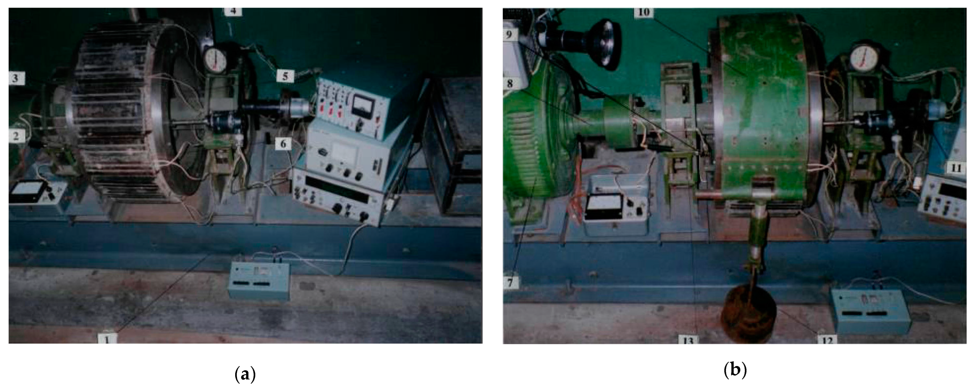
Figure 1. General view of the workbench with a band brake with an open (a) and a closed brake band (b): 1—frame beams; 2, 3, 4—friction pads with external and internal working surfaces, respectively; 5—brake pulley, 6—thermocouple terminals; 7—electric motor for driving the brake pulley; 8—brake pulley shaft with elastic coupling; 9—outputs of the microammeter; 10—brake band; 11—tachometer; 12—load node; 13—shaft bearing supports.
Lubricants 12 00172 g001
Figure 2. The brake belt (a) and bandage made of friction pads (b) are the main components of a multi-pair friction unit: 1—main brake belt; 2—additional brake tape; 3—fastening elements of friction pads.
Lubricants 12 00172 g002
Figure 3. General view of the friction units of the belt brake with sensors: 1—the main brake belt; 2—additional brake tape; 3—friction pads; 4—brake pulley; 5—bearing supports of the brake pulley; 6—load node; 7—connecting wires of sensors.
Lubricants 12 00172 g003
Figure 4. Images of brake pad surface: (a) taken perpendicular to its surface; (b) taken from a particular angle that allows us to avoid glares.
Lubricants 12 00172 g004
Figure 5. Formation of a brake pad image taken from a particular angle that allows us to avoid glares.
Lubricants 12 00172 g005
Figure 6. Dependence of the friction coefficient on temperature for a friction pad (FK-24A) paired with a steel brake pulley (30ChGSA).
Lubricants 12 00172 g006
Figure 7. General appearance of the drilling drawwork after a long period of operation (a) and different types of cracks on the working cylindrical surface of the brake pulley: (b) an ensemble of surface cracks; (c) one main through crack; (d) one trunk crack (enlarged view).
Lubricants 12 00172 g007
Figure 8. SEM image of the friction surface of the brake pad in a worn state without cracks at different magnifications, (a,b), spectrum of 1 (c) and elemental composition of the worn material (d).
Lubricants 12 00172 g008
Figure 9. SEM image of the friction surface of the brake pad in a worn state with cracks at different magnifications, (a,b), the spectrum of 1 section in the crack zone (c) and the elemental composition of the worn material (d).
Lubricants 12 00172 g009
Figure 10. SEM image of the friction surface of the brake pad in a worn state with cracks (a,b), spectrum 1 for the area far from the crack (c) and spectrum 2 for the area near the crack (d) and, accordingly, the elemental compositions of the worn material (e,f).
Lubricants 12 00172 g010
Figure 11. SEM image of the worn brake pad surface for the EDXS analysis (a) and the results of the EDS analysis: (b)—C; (c)—O; (d)—Si; (e)—Ca; (f)—Ba; (g)—Fe; (h)—Mn; (i)—Cr.
Lubricants 12 00172 g011
Figure 12. Mapping results: (a) obtained image; (b) restored image of the surface of a brake pad.
Lubricants 12 00172 g012
Figure 13. Restored input image of brake pad (a), visualization of its measure L c (b) and their respective segmentation by Otsu method: (c,d).
Lubricants 12 00172 g013
Figure 14. Results of contour detection (a) and skeletonization (b) of image in Figure 13d.
Lubricants 12 00172 g014
Table 1. Chemical composition of 30ChGSА steel, mass % (Interstate Standard GOST 4543–2016 [104]).
CSiMnCrPSFe
0.28–0.340.90–1.200.80–1.100.80–1.10≤0.035≤0.035The rest
Table 2. Physical and mechanical characteristics of 30ChGSA steel (Interstate Standard GOST 4543–2016 [104]).
Hardness
HB
Density,
kg/m3
Strength
Limit,
MPa
Young’s Modulus
E·10–5,
MPa
Impact Strength,
kJ/m2
Coefficient of Linear Expansion
α·106,
1/°C
Thermal Conductivity Coefficient
Wt/(м·°C)
Specific Heat Capacity,
J/(kg·°C)
220785010802.149011.738496
Table 3. Physical and mechanical characteristics of retinax friction material [106].
Friction MaterialHardness HBDensity, kg/m3Limit of Compressive Strength, MPaYoung’s Modulus E·10−5, MPaImpact Strength, kJ/m2Thermal Conductivity Coefficient, Wt/(м·°C)Thermal Conductivity Coefficient,
kJ/(kg·°C)
Thermal Shrinkage, %
FK-24A30–492130–2450736902.50.580.960.45
Table 4. Segmentation results for surface defects.
NoP1, %P2, %P3, %
111.539.845.22
212.8310.806.03
318.5514.988.48
418.4215.838.76
Disclaimer/Publisher’s Note: The statements, opinions and data contained in all publications are solely those of the individual author(s) and contributor(s) and not of MDPI and/or the editor(s). MDPI and/or the editor(s) disclaim responsibility for any injury to people or property resulting from any ideas, methods, instructions or products referred to in the content.