Article

Modeling and Dynamic Analysis of Double-Row Angular Contact Ball Bearing–Rotor–Disk System

1
College of Mechanical and Electrical Engineering, Central South University, Changsha 410083, China
2
State Key Laboratory of Precision Manufacturing for Extreme Service Performance, Central South University, Changsha 410083, China
3
Hunan Aviation Powerplant Research Institute, Aero Engine Corporation of China, Zhuzhou 412002, China
4
School of Civil Engineering, Central South University, Changsha 410075, China
*
Author to whom correspondence should be addressed.
Lubricants 2024, 12(12), 441; https://doi.org/10.3390/lubricants12120441
Submission received: 16 October 2024 / Revised: 29 November 2024 / Accepted: 2 December 2024 / Published: 10 December 2024

Abstract

:
This article presents a general numerical method to establish a mathematical model of a bearing–rotor–disk system. This mathematical model consists of two double-row angular contact ball bearings (DRACBBs), a rotor and a rigid disk. The mathematical model of the DRACBB is built on the basis of elastic Hertz contact by adopting the Newton Raphson iteration method, and three different structure forms are taken into account. The rotor is modeled by employing a finite element method in conjunction with Timoshenko beam theory, and the rigid disk is modeled by applying the lumped parameter method. The mathematical model of the bearing–rotor–disk system is constructed by the coupling of the bearing, rotor and disk, and the dynamic response of the bearing–rotor–disk system can be solved by employing the Newmark-β method. The validation of the above mathematical model is demonstrated by comparing the proposed results with the results from the existing literature and finite element software. The dynamic characteristics of the DRACBBs and the dynamic response of the bearing–rotor–disk system are investigated by parametric study. A dynamic characteristic analysis of the DRACBB is conducted to ensure the optimal structure form of the DRACBB under complex external loads, and it can provide a reference for the selection of the structural forms of DRACBBs.

1. Introduction

The bearing–rotor–disk system is used widely in the power systems of aero-engines due to the fact that it has excellent mechanical properties that can withstand large centrifugal and aerodynamic loads. In view of the high speed and complex and harsh load conditions that frequently characterize aero-engine services, the dynamic characteristics of the bearing–rotor–disk system have an important influence on the stability and reliability of the aero-engine. In order to improve the dynamic performance of aero-engines, many scholars have carried out extensive research work with regard to the dynamic modeling and dynamic characteristics analysis of the substructure of bearing–rotor–disk systems over the past decades, and some research results can provide a reference point for the investigation addressed in this article.
Parmar and Saran [1] analyzed the nonlinear dynamic behaviors of a double-row, self-aligning shaft–bearing system subjected to varying shaft speeds and load working conditions, and the bearing was simulated by using nonlinear springs in this system. Li et al. [2] constructed a numerical model of a rotor–bearing system with bolted-disk joints under unbalanced forces by using a lumped-mass modeling method and the Newmark-β approach to investigate the vibration characteristics of this system. Brahimi et al. [3,4,5] investigated the nonlinear dynamic behaviors, including the bifurcation and chaotic behaviors, of a flexible rotor–active magnetic bearings system by using the Runge–Kutta method. Ma et al. [6] analyzed the influences of the eccentric phase differences between two discs on the oil-film instability behaviors of a rotor–bearing system by establishing lumped-mass, spring-damping and nonlinear oil-film force models. She et al. [7,8] researched the coupling vibration behaviors of a flexible rotor–disk–blade system under working conditions with varying rotating speeds. Yang et al. [9,10,11] studied the coupling vibration behaviors of a shaft–disk–blade system by using the combination energy approach and the assumed modes method, systematically investigating the effects of the flexibility of the disk on the coupling vibration of this system. Ding et al. [12] built an experimental test rig for verifying the dynamic response results of a multi-bearing rotor, calculated using a numerical method. Li et al. [13] set up a continuum dynamic model for analyzing the nonlinear behaviors of a flexible blade–rotor–bearing coupling system. Ma et al. [14,15,16] developed a finite element model of a shaft–disk–blade (SDB) system for analyzing the effects of external working conditions on the vibration response of an SDB system. The shaft and blade were simulated by adopting Timoshenko beam elements, the disk was simulated by using a shell element, and the bearings were simulated by applying spring-damping elements. Lu et al. [17] established a dynamic model of a flexible blade–disk rotor system supported by rolling bearings and investigated the influences of multi-stage blade structure parameters on the bifurcation characteristics of this system. Zhou et al. [18] presented a universal model for investigating the coupled vibration response of a flexible-disk rotor system with lacing wires by using the assumed mode method and the finite element method. Zhao et al. [19] proposed a universal numerical modeling approach for analyzing the coupling vibration behaviors of shaft–disk–drum rotor systems with elastic connections and supports, based on Euler–Bernoulli’s beam theory, Kirchhoff’s plate theory and Sanders’ shell theory. Tuzzi et al. [20] developed a full 3D finite element model for investigating the effect of asymmetric bearing support on the mechanisms of cross-disc coupling. Mereles et al. [21,22] presented a continuous segment method for establishing a dynamic model of complex rotor systems with multiple disks and bearings, and this dynamic model can be used to solve the eigenvalue problem of the system. Khorrami et al. [23] discussed the vibration response characteristics of a rotor–disk–bearing system with one or two cracks by applying the harmonic balance method and assuming the bearing to be rigid supporting. Behdinan et al. [24,25] analyzed the force transmissibility and frequency response behaviors of a flexible shaft–disk rotor supported by a nonlinear suspension system by applying the assumed mode method and regarding the bearing as having nonlinear stiffness and damping. Li et al. [26] constructed a dynamic response model of a flexible stepped shaft–bearing by using the improved Newton Raphson method and differential quadrature method. Wang et al. [27] researched the vibration responses of a rotor–bearing system with angular misalignment and cage fracture by using simulations and experiments. Cao et al. [28] developed a mechanical model of a rolling bearing–rotor system, and five kinds of rolling bearing models, including the lumped-parameter model, quasi-static model, quasi-dynamic model, dynamic model and finite element model, were summarized.
As a typical mechanical supporting component of a bearing–rotor–disk system, a double-row (duplex) bearing is superior to a single-row bearing in some respects, including its rotating accuracy, bearing stiffness, operating stability and load-carrying capacity. Petersen et al. [29] established a quasi-static model of a double-row rolling-element bearing with raceway defects to solve the dynamic characteristics of such bearings. Gunduz et al. [30] developed a new theory for solving the stiffness matrix of DRACBBs. Zhang et al. [31] proposed a new algorithm for calculating the stiffness characteristics of combined angular contact ball bearings. Yang et al. [32] established a three-degrees-of-freedom dynamic model for investigating the mechanical behaviors of double-row taper roller bearings under external loads and angular misalignment. Ai et al. [33] developed a quasi-static model for analyzing the temperature rise of double-row tapered roller bearings by using the thermal network method. Gunduz et al. [34] investigated the influences of preloading mechanisms on the vibration response of DRACBB–rotor systems. Xu et al. [35,36] proposed a comprehensive mathematical model for solving the stiffness characteristics of DRACBBs, and three configurations were taken into account.
According to the existing research results, it is easy to see the types of dynamic modeling with regard to bearing–rotor–disk systems under various external load working conditions. However, the bearing element of the bearing–rotor–disk system is regarded as elastic supporting, and the bearing is equivalent to nonlinear springs and dampeners in general, which ignores the variation in the internal structure of bearings in the existing literature. In order to make up for this shortcoming, a unified dynamic model of bearing–rotor–disk systems is proposed in this paper, and the internal structure of the bearing is taken into account. The bearings in this system are selected as DRACBBs due to their series of advantages, including their high bearing capacity, operating stability and long service life. A dynamic model of a DRACBB is established on the basis of nonlinear Hertz contact, and it is solved by employing the Newton Raphson method. Five degrees of freedom are considered. The shaft and disk are modeled by using Timoshenko beam theory and the lumped-mass method, respectively, and six degrees of freedom are considered. The bearing, rotor and disk are coupled by means of common nodes, and the dynamic behaviors of the bearing–rotor–disk system are solved by using the Newmark-β method.

2. Mathematical Model

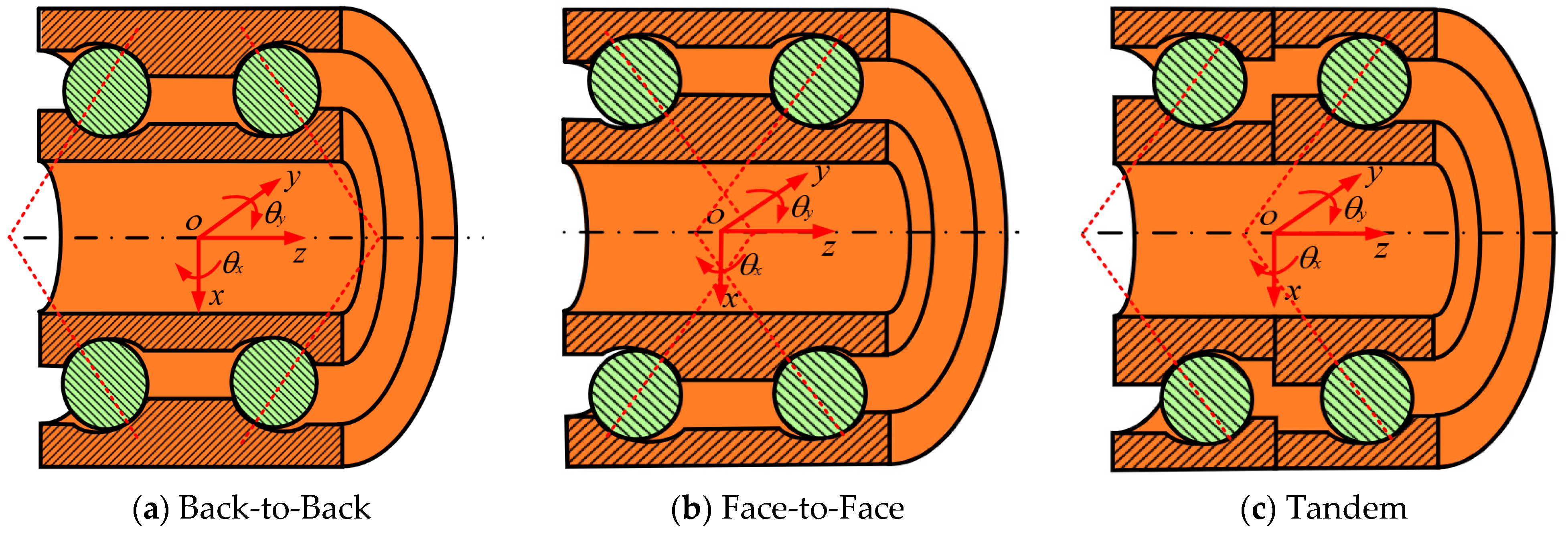
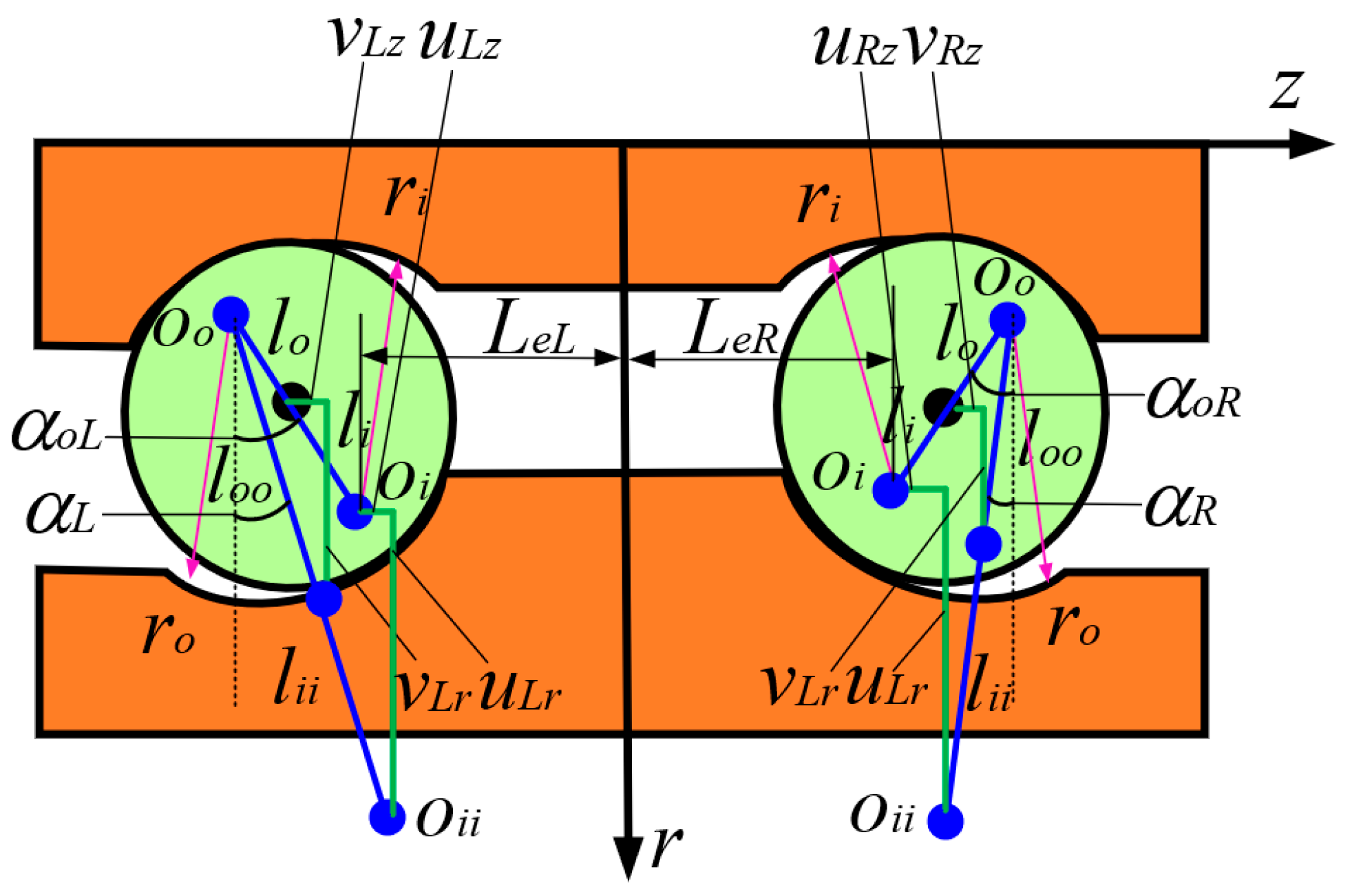
2.1. The Equations of Motion of the DRACBB

According to the existing literature, a DRACBB cannot simply be regarded as the superposition of two single-row angular contact ball bearings. In other words, the traditional modeling approach for single-row angular contact ball bearings is not suitable for calculating the dynamic characteristics of DRACBBs. The DRACBBs can be divided into three different structural forms according to the actual load line; these specific structural forms are shown in Figure 1.
As shown in Figure 1, the structural forms of DRACBB are named Back-to-Back, Face-to-Face and Tandem. Because the internal structure of a DRACBB is complex, the model needs to be simplified by applying some model assumptions, which are as follows: (a) Each row’s angular contact ball has the same structural parameters. (b) The ball center and the inner and outer raceway curvature centers remain collinear under external loads. (c) The friction, lubrication, skidding and slipping of the ball and raceway are neglected. (d) The inner ring of the bearing rotates with the rotor, and the outer ring of the bearing is fixed. The centrifugal force and gyroscopic moment caused by the rolling element are neglected. (e) The axial and radial forces are assumed to be 0 at the free contact angle. In order to obtain the motion equation for DRACBBs, a geometric analysis of DRACBBs was performed, and the Back-to-Back structure form of DRACBBs was selected as the research object. The corresponding results are displayed in Figure 2 and Figure 3.
As shown in Figure 2, the global and local coordinate systems are described by using Cartesian and cylindrical coordinate systems, respectively. The inner ring of the bearing considers five degrees of freedom, comprising x, y, z, θx and θy, and the jth rolling element of the bearing considers three degrees of freedom, comprising ukzj, vkzj and θkzj (k = L, R). The azimuth of the jth rolling element can be expressed as
ψ j = ω c t + 2 π N j 1 ;   ω c = 1 2 ω s 1 D D m cos α o
where ωc and ωs are the rotating speeds of the cage and shaft, respectively; N is the number of single-row angular contact ball bearings; j is the jth rolling element (ball), and the range of j varies from 0° to 360°; αo denotes the contact angle; D and Dm express the diameter of the rolling element and the pitch diameter of the DRACBB, respectively. For the derivation of the following formula, some parameters need to be explained further.
c 1 = 1 ; k = L 1 ; k = R ; c 2 = 1 ; Back - to - back 1 ; Face - to - face c 1 ; Tan dem
Here, c1 is used to describe the location of the left and right rows of the DRACBB, and c2 is used to describe the structural form of the DRACBB [30]. The axial and radial distances of the inner raceway curvature centers of a single-row angular contact ball bearing can be expressed as
R k ( L , R ) = D m 2 + r i 0.5 D cos α o L e k ( L , R ) = B 4 + c 2 r i 0.5 D sin α o
where ri and B are the inner raceway curvature radius and bearing width of the DRACBB, respectively.
From Figure 3, the relationships between the locations of the ball center and the inner and outer raceway curvature centers of a DRACBB subjected to static and non-static states can be expressed as follows:
l i o = l i + l o ;   l i = r i 0.5 D l o = r o 0.5 D
l ¯ i o k j = l i i + l o o k j = l i o cos α o + u k r j 2 + l i o sin α o + c 1 c 2 u k z j 2
Based on the above geometric analysis, the contact angle of the DRACBB can be ascertained; the corresponding expressions are as follows and are based on the Pythagorean theorem.
sin α k j = l i o sin α o + c 1 c 2 u k z j l ¯ i o k j = l i o sin α o + c 1 c 2 u k z j l i o cos α o + u k r j 2 + l i o sin α o + c 1 c 2 u k z j 2 cos α k j = l i o cos α o + u k r j l ¯ i o k j = l i o cos α o + u k r j l i o cos α o + u k r j 2 + l i o sin α o + c 1 c 2 u k z j 2
For the sake of the following discussion, the relationship between the displacements of the inner ring and rolling element center needs to be determined as follows; the detailed derivation process can be found in the existing literature [35].
u k j = R k j δ u k j = u k r j u k z j θ k z j T ;   δ = δ x δ y δ z θ x θ y T R k j = cos ψ j sin ψ j 0 c 1 L e k sin ψ j c 1 L e k cos ψ j 0 0 1 R m sin ψ j R m cos ψ j 0 0 0 sin ψ j cos ψ j
Here, ukj and δ are the displacement column vectors of the kjth rolling element and inner ring, respectively; Rkj denotes the displacement transformation matrix.
In order to ascertain the equilibrium equations for double-row angular contact ball bearings, the contact force between the rolling element and raceway must first be determined; the specific expression with regard to the contact force is as follows, according to Hertzian contact theory [36]:
Q k j = K n δ k j 3 / 2 ; δ k j > 0 0                 ; δ k j 0 δ k j = l ¯ i o k j l i o = l i i + l o o k j l i + l o
where δkj is the deformation of the distance of the inner and outer raceway curvature centers. Kn denotes the contact stiffness coefficient, and its specific expression can be written as follows:
K n = 1 / 1 K i 2 3 + 1 K o 2 3 3 2
where Ki and Ko represent the contact stiffness coefficients between the rolling element and the inner and outer raceways. The concrete expressions of Ki and Ko, according to the existing literature [36], are shown in Appendix A.
For the sake of the following derivation, the contact force Qkj needs be decomposed along the radial ukzj, axial vkzj and torque θkzj directions; the decomposition results for the contact force Qkj are as follows, according to reference [36].
Q k j = Q k r j Q k r j T k j = Q k j cos α k j c 1 c 2 Q k j sin α k j 0
According to the transformation matrix Rkj obtained above, the force of the jth rolling element on the inner ring of a double-row angular contact ball bearing can be described as follows:
f k j = R k j T Q k j ;   f k j = f k x j f k y j f k z j M k x j M k y j T
where fkj denotes the force vector, which is used to describe the effect of the jth rolling element on the inner ring. According to the above discussion, the equilibrium equation with regard to inner ring of the DRACBB can be expressed as follows:
F e + k = L k = R j = 1 N f k j = 0 ;   F e = F x F y F z M x M y T
where Fe denotes the external load vector of the DRACBB. After variable substitution, Equation (12) is expressed in the following form.
E q 1 = F x k = L k = R j = 1 N Q k j cos α k j cos ψ j = 0 E q 2 = F y k = L k = R j = 1 N Q k j cos α k j sin ψ j = 0 E q 3 = F z k = L k = R j = 1 N c 1 c 2 Q k j sin α k j = 0 E q 4 = M x k = L k = R j = 1 N Q k j c 1 L e k cos α k j + c 1 c 2 R k sin α k j sin ψ j = 0 E q 5 = M y k = L k = R j = 1 N Q k j c 1 L e k cos α k j c 1 c 2 R k sin α k j cos ψ j = 0
Equation (13) is solved by using the Newton Raphson iteration method; the corresponding expression is as follows:
δ i + 1 = δ i K b 1 E q E q = E q 1 E q 2 E q 3 E q 4 E q 5 T K b = E q δ T = E q 1 δ x E q 1 δ y E q 1 δ z E q 1 θ x E q 1 θ y E q 2 δ x E q 2 δ y E q 2 δ z E q 2 θ x E q 2 θ y E q 3 δ x E q 3 δ y E q 3 δ z E q 3 θ x E q 3 θ y E q 4 δ x E q 4 δ y E q 4 δ z E q 4 θ x E q 4 θ y E q 5 δ x E q 5 δ y E q 5 δ z E q 5 θ x E q 5 θ y
According to the iterative solution above, the dynamic characteristics of a DRACBB under complex-load external working conditions can be determined. It is worth noting that the iterative solution accuracy and maximum number of iterations are set to 1 × 10⁻⁸ and 10,000, respectively, in the progress of this Newton Raphson iteration.

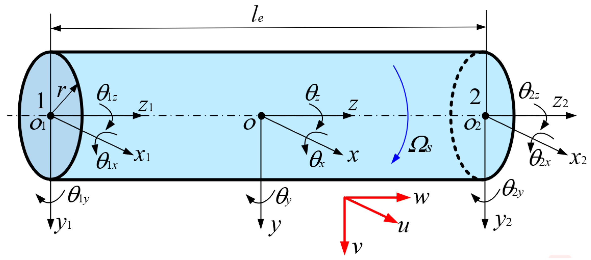
2.2. The Equations of Motion of the Rotor and Disk

The dynamic model of the rotor is established by using a two-node beam element based on Timoshenko beam theory. As shown in Figure 4, the geometric model of the two-node beam element is described by employing a Cartesian coordinate system, and six degrees of freedom are considered. The symbols xi, yi and zi (i = 1, 2) are used to describe the translational displacements of the nodes along the x, y and z axes, respectively; the symbols θxi, θyi and θzi (i = 1, 2) are used to express the rotational displacements of the nodes about the x, y and z axes, respectively.
According to the energy principle, the expressions of kinetic and potential energy are as follows based on Timoshenko beam theory [26]:
T e = 1 2 0 l e ρ r S r u ˙ 2 + v ˙ 2 + w ˙ 2 + ρ r I r 2 Ω s + θ ˙ z 2 + θ ˙ x + θ ˙ y 2 + 2 Ω s + θ ˙ z θ ˙ y θ ˙ x θ ˙ x θ ˙ y d z
U e = 1 2 0 l e E r S r w z 2 + E r I r θ x z 2 + θ y z 2 + 2 G r I r θ z z 2 + κ r G r S r u z θ y 2 + θ x v z 2 d z
where le is the length of the beam element; u, v and w denote the displacement components along the x, y and z axes, respectively; the symbol “˙” denotes derivation with respect to time t; ρr is the density of the rotor; Er and Gr are the elasticity and shear modulus, respectively; Sr and Ir denote the section area and inertia moment, respectively; κr denotes the shear deformation factor, and it is selected as π2/12. The expressions of the above parameters are as follows:
S r = π 4 D r 2 ,   I r = π 64 D r 2 G r = E r 2 1 + ν ,   k r = 6 1 + ν 7 + 6 ν
where Dr and ν denote the diameter of the rotor and the Poisson ratio, respectively. According to the above energy expressions for the beam, the Lagrange formula, and the finite element method, the governing equation for the two-node beam element can be written in the following form:
M r e q ¨ r e + ( C r e + G r e ) q ˙ r e + K r e q r e = 0 q r e = x 1 y 1 z 1 θ x 1 θ y 1 θ z 1 x 2 y 2 z 2 θ x 2 θ y 2 θ z 2 T
where q r e denotes the displacement column vector; M r e , G r e and K r e express the mass, gyroscopic and stiffness matrices of the beam element, the concrete expressions of which can be found in Appendix B; C r e represents the damping matrix, which can be determined from the mass matrix M r e and stiffness matrix K r e . The concrete expression of C r e is as follows:
C r e = α M r e + β K r e α = 4 π f 1 f 2 f 1 ξ 2 f 2 ξ 1 f 1 2 f 2 2 ;   β = ξ 2 f 2 ξ 1 f 1 π f 2 2 f 1 2 ;   ξ 1 = ξ 2 = 0.5 q r e = x 1 y 1 z 1 θ x 1 θ y 1 θ z 1 x 2 y 2 z 2 θ x 2 θ y 2 θ z 2 T
where f1 and f2 are the first- and second-order natural frequencies with regard to the rotor, respectively.
The dynamic model of the disk is constructed by using the lumped-mass method, because the flexibility of the disk in rotating machinery is generally ignored. The geometric model of the disk is shown in Figure 5. From Figure 5, it is not hard to see that the dynamic model is described by employing a Cartesian coordinate system, and six degrees of freedom are considered.
Here, Oc and Od denote the centroids of the disk under static and non-static conditions, respectively; e and θd denote the eccentric distance and angular displacement of the disk, which are caused by the rotating speed Ωd. Because the disk is regarded as a concentrated mass point, only the kinetic energy of the disk is taken into account in this study. According to the energy principle, the expression for kinetic energy is written as follows.
T d = 1 2 J p d θ ˙ d + θ ˙ z d 2 + 1 2 m d u ˙ d + v ˙ d + w ˙ d 2 J p d θ ˙ d + θ ˙ z d θ ˙ x d θ ˙ y d + 1 2 J d θ ˙ x d + θ ˙ y d
where u d , v d and w d denote the displacement components of Oc along the x, y and z axes, and the symbol “˙” denotes derivation with regard to time t; θxd, θyd and θzd express the rotational displacement components of Oc. it is worth mentioning that the expressions of the above displacement components can be written as follows:
u d = x d + e cos θ d + θ z d v d = y d + e sin θ d + θ z d w d = z d
where xd, yd and zd express the horizontal, vertical and axial displacements of Oc; md is the mass of the disk. Jpd and Jd denote the polar inertia moment and the inertia moment of the disk, respectively, and their concrete expressions are as follows:
J p d = 1 2 m d r d 2 + R d 2 J d = 1 12 m d 3 r d 2 + R d 2 + h d 2
where rd, Rd and hd denote the inner radius, outer radius, and thickness of the disk. Analogously to the energy expression s of the beam element, the governing equation for the disk is obtained:
M d q ¨ d + G d q ˙ d = 0 q d = x d y d z d θ x d θ y d θ z d T
where qd is the displacement column vector; Md and Gd are the mass and gyroscopic matrices, respectively, the specific expressions for which are as follows:
M d = m d 0 0 0 0 0 0 m d 0 0 0 0 0 0 m d 0 0 0 0 0 0 J d 0 0 0 0 0 0 J d 0 0 0 0 0 0 J p ;   G d = ω d 0 0 0 0 0 0 0 0 0 0 0 0 0 0 0 0 0 0 0 0 0 0 J p 0 0 0 0 J p 0 0 0 0 0 0 0 0
where ωd is the angular velocity, which is determined by the rotating speed Ωd.

2.3. The Equations of Motion of the Bearing–Rotor–Disk System

Through the above derivations, motion equations for the bearing, rotor and disk have been determined. The bearing–rotor–disk system is made up of bearings, a rotor and a disk, and the specific geometric model is shown in Figure 6.
As shown in Figure 6, the bearing–rotor–disk system consists of two DRACBBs, one stepped rotor that contains three shaft segments, and one disk. It is worth noting that the above three components are coupled by means of common nodes. The symbols L1, L2 and L3 denote the respective lengths of shaft segments of the rotor; the symbols R1, R2 and R3 express the respective radii of shaft segments of the rotor; the symbols R4 and R5 denote the inner and outer radii of the disk; the symbol h denotes the thickness of the disk; mo and ms are the centroids of the rotor–bearing system under static and non-static conditions; and the distance between mo and ms is named the eccentric distance e. The global bearing–rotor–disk system is established by adopting a Cartesian coordinate system, and it is consistent with the coordinate systems for the rotor and disk. However, the global coordinate system is not consistent with the coordinate system for the DRACBBs. In order to conveniently realize the above coupling, a coordinate transformation needs to be carried out, and the stiffness matrix of the left and right DRACBBs is revised as follows:
K b L = K b R = T b T K b T b T b = 0 1 0 0 0 1 0 0 0 0 0 0 1 0 0 0 0 0 0 1 0 0 0 1 0
According to the mass, gyroscopic and stiffness matrices of the beam element, the corresponding matrices with regard to the rotor can be determined.
M r q ¨ r + ( C r + G r ) q ˙ r + K r q r = 0 q r = x 1 y 1 z 1 θ x 1 θ y 1 θ z 1 x 2 N y 2 N z 2 N θ x N θ y N θ z N N 1 + N 2 + N 3 + 1 × 6 T
Q M , C , G , K r = Q r 1 Q r 2 Q r 3 N 1 + N 2 + N 3 + 1 × 6 Q M , C , G , K r i i = 1 , 2 , 3 = Q r e Q r e Q r e Q r e N i + 1 × 6
Here, N1, N2 and N3 denote the respective numbers of beam elements of shaft segments of the rotor; the values of N1, N2 and N3 were set as 10, 20 and 10, respectively, in this study. Through the above model derivation, the global governing equation for the bearing–rotor–disk system is ascertained as follows:
M r + M d q ¨ r + ( C r + G r + G d ) q ˙ r + K r + K b L + + K b R q r = F e
where Fe is force vector that is caused by the eccentricity of the rotor and disk and is located at the middle of the rotor. The matrix dimension of Fe is consistent with the matrix dimension of qr, and the specific form of Fe can be written as follows:
F e = F x 1 F y 1 F z 1 M θ x 1 M θ y 1 M θ z 1 F x N F y N F z N M θ x N M θ y N M θ z N T F x N 1 + N 2 + N 3 2 + 1 = m e ω 2 sin ω t ;   F y N 1 + N 2 + N 3 2 + 1 = m e ω 2 cos ω t ;   ω = 2 π 60 Ω s ;   e = 1000 G ω × 10 6 m = m r + m d ;   m r = ρ r π R 1 2 L 1 + R 2 2 L 2 + R 3 2 L 3 ;   m d = ρ r π h R 5 2 R 4 2
where G is the precision class of the bearing–rotor–disk system; the value of G was set to 6 in this study. The left and right double-row angular contact ball bearings were applied at the start and end nodes of the rotor, respectively. The external-load working conditions of the double-row angular contact ball bearings can be determined by the force vector of the bearing–rotor–disk system.
F x L , R = 1 2 m e ω 2 sin ω t F y L , R = 1 2 m e ω 2 cos ω t F z L , R = F z M x L , R = M x M y L , R = M y
The governing equation of the bearing–rotor–disk system contains a time variable and has strong nonlinearity, so it can be solved by using the Newmark-β method. The dynamic response of the bearing–rotor–disk system can be obtained by solving the above governing equation.

3. Results and Discussion

Through the above derivation of the motion equation, a mathematical model of the bearing–rotor–disk system was constructed. Based on the established dynamic model, a mathematical model validation and dynamic characteristic analysis were carried out as described in this section. The mathematical model validation comprises model validations of the DRACBB and rotor–disk system. The dynamic characteristic analysis comprises two parts: a dynamic characteristic analysis of the DRACBB and a dynamic response analysis of the bearing–rotor–disk system; the investigation of the former can provide theoretical guidance for the research of the latter.

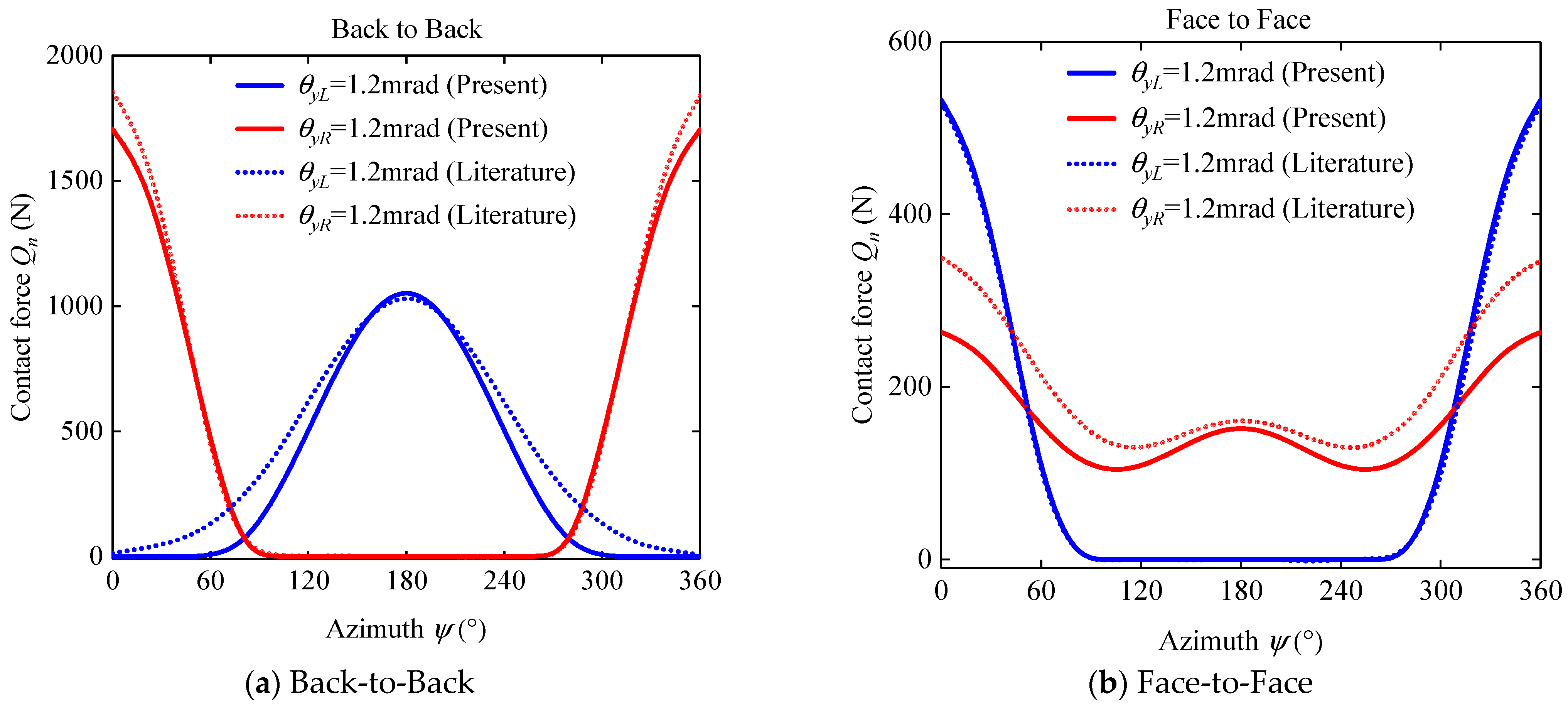
3.1. Mathematical Model Validation

The mathematical model validation of the DRACBB was carried out firstly by comparing the results of the proposed model and the results in the existing literature; the comparison results are given in Figure 7. The structural parameters of the DRACBB are given in Table 1. The external forces were selected as follows: Fx = 2500 N, Fy = 0, Fz = 500 N, Mx = My = 0 N·m.
As shown in Figure 7, some errors were found in the comparison results. However, the variation tendency in the calculation results for the contact force from the proposed model is the same as that in the results from the existing literature [36]. From these comparison results, it is not hard to infer that the validation of the presented model of a DRACBB can be used to solve the dynamic characteristics of DRACBBs subject to external loads.
Then, a model validation of the rotor–disk system was performed. The model parameters of the rotor–disk system were as follows: E = 2.1 × 10¹¹ Pa; v = 0.3; ρ = 7800 kg/m3; R1 = R4 = 25 mm, R2 = 50 mm, R3 = 150 mm; L1 = L3 = 0.5 m; L2 = 1 m; hd = 40 mm. The comparison results of the natural frequency of the rotor–disk system are displayed in Table 2 and Table 3.
As shown in Table 2 and Table 3, the calculation results for the natural frequency of the rotor–disk system under static and non-static conditions calculated by the proposed mathematical model have good consistency with the results from ANSYS 2022R1 finite element software. The model of the rotor–disk system was thus verified according to these comparison results.
To sum up, the mathematical models of the DRACBB and rotor–disk system were verified. Thus, the mathematical model of the bearing–rotor–disk system was indirectly validated, and it can be used to solve for the dynamic characteristics of bearing–rotor–disk systems.

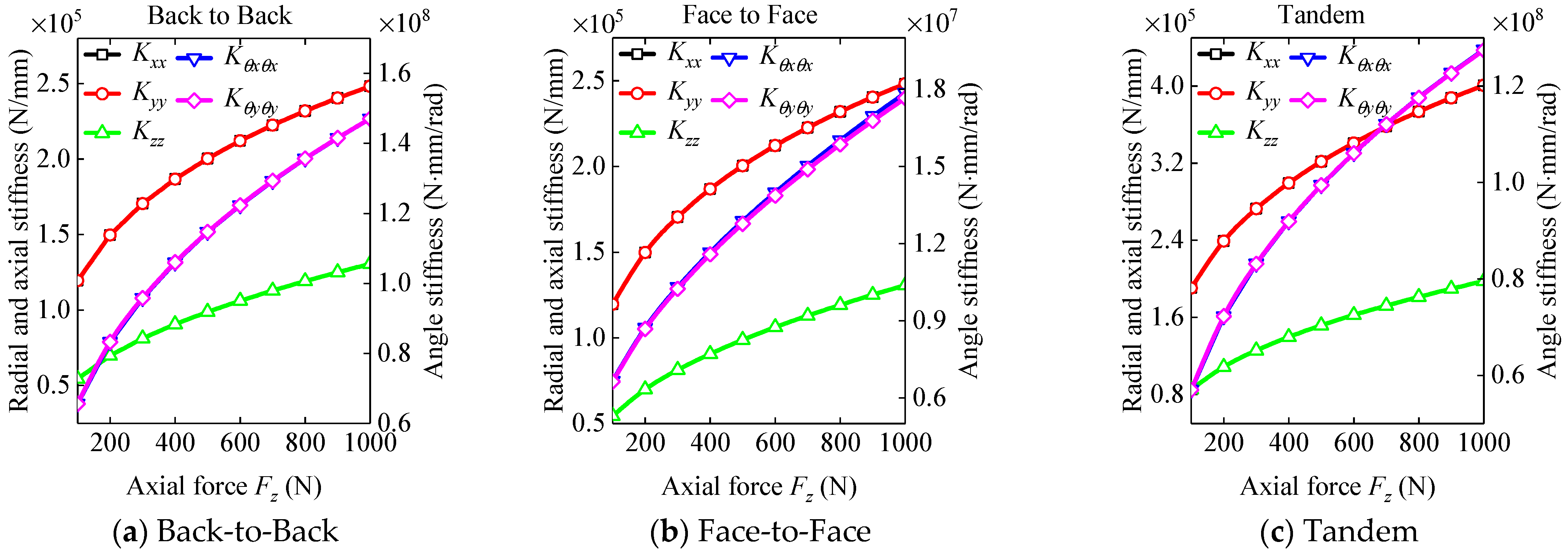
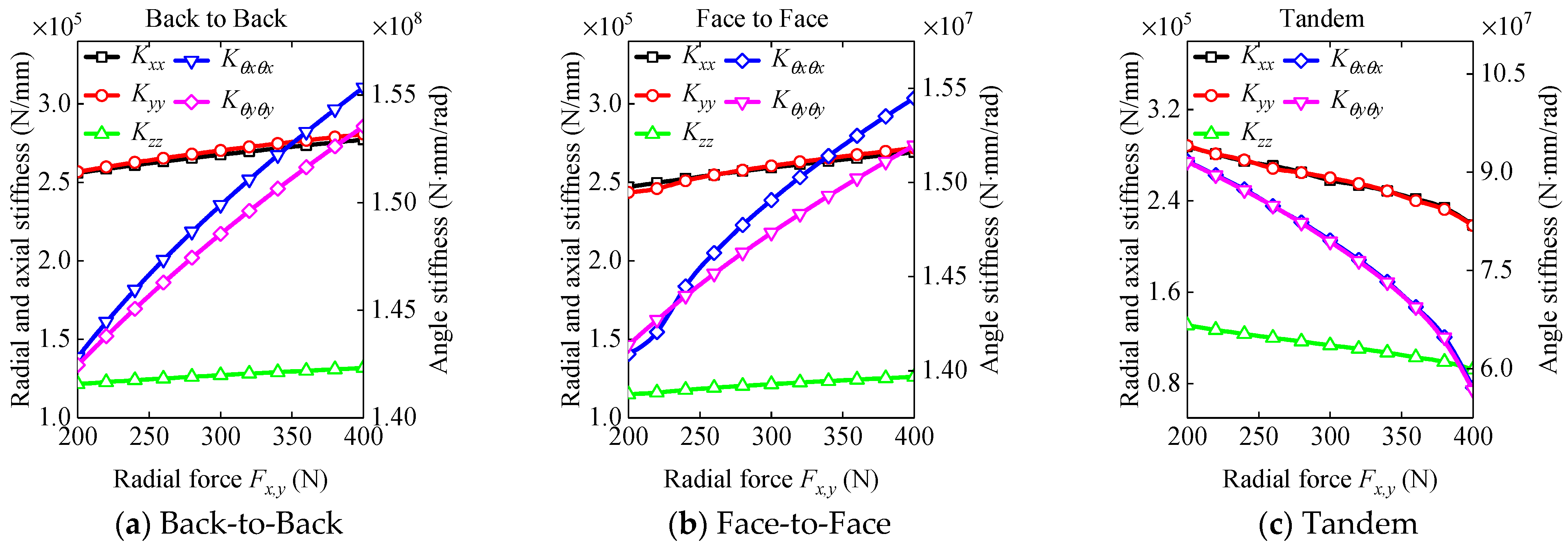
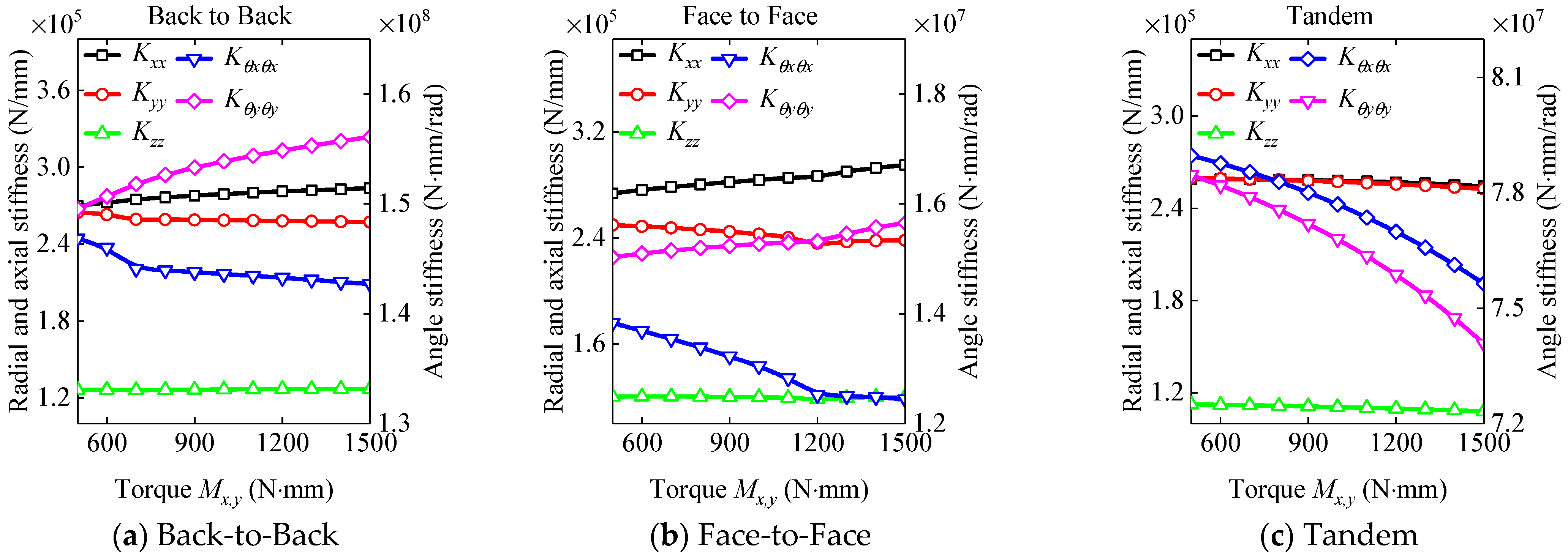
3.2. The Dynamic Characteristic Analysis of the DRACBB

After the above mathematical model validation, the dynamic behaviors of DRACBBs under external loads and different structural forms are discussed systematically. The structural parameters of DRACBBs were introduced in Section 3.1.
Firstly, the effects of axial force Fz on the contact characteristics and dynamic stiffness of DRACBBs under different structural forms are discussed; the research results are shown in Figure 8 and Figure 9.
From Figure 8, the left- and right-row contact angles and contact forces of DRACBBs under Back-to-Back and Face-to-Face present a bifurcation phenomenon as the axial force Fz increases, but the variation tendencies of the contact angle and contact force are opposite. With an increase in the axial force Fz, the contact angles and contact forces of DRACBBs under Tandem increase, and the variation tendencies of the left- and right-row contact angles and contact forces are consistent. From Figure 9, the axial, radial and angle stiffness of DRACBBs under Back-to-Back, Face-to-Face and Tandem increase as the axial force increases. It is worth mentioning that the radial stiffness of DRACBBs under Tandem is the largest among the structural forms, while the angle stiffness of DRACBBs under Back-to-Back is the largest among the structural forms.
Secondly, the influences of radial force Fy and Fz on the contact characteristics and dynamic stiffness of DRACBBs with different structural forms are discussed; the research results are given in Figure 10 and Figure 11. The axial force Fz was set to 1000 N, and the radial force Fx and Fy are consistent in the following discussion.
As shown in Figure 10, the left- and right-row contact angles of DRACBBs under Back-to-Back, Face-to-Face and Tandem vary sinusoidally with the azimuth. The variation tendencies of the left- and right-row contact angles under Back-to-Back and Face-to-Face are opposite, and the variation tendencies of the left- and right-row contact angles under Tandem are consistent. The amplitude of the sinusoidal curve increases with an increase in radial force Fx and Fy. The variation tendencies of the left- and right-row contact forces under Back-to-Back and Face-to-Face are opposite: one row contact force of the DRACBB varies sinusoidally with the azimuth, and the other row contact force varies firstly in a ‘V’ shape and then remains constant as the azimuth increases. The left-row contact force under Tandem varies by means of a cosine curve, and the variation tendency of the right-row contact force with the azimuth under Tandem is consistent with the right-row contact force under Back-to-Back. The amplitudes of the sine curves of the left- and right-row contact angles under Tandem are the largest among the structural forms of the DRACBBs. The amplitudes of the left- and right-row contact forces under Back-to-Back are the largest among the structural forms of the DRACBBs.
As shown in Figure 11, the dynamic stiffness of DRACBBs under Back-to-Back and Face-to-Face increases with an increase in radial force. The angle stiffness Kθxθx and Kθyθy under Back-to-Back present a bifurcation phenomenon with an increase in radial force. The radial stiffness Kxx and Kyy remain basically consistent with an increase in radial force. However, the dynamic stiffness of DRACBBs under Tandem decreases with an increase in radial force, while the radial stiffness and angle stiffness remain consistent with an increase in radial force. We can infer that an increase in radial force reduces the stiffness of DRACBBs under Tandem.
Finally, the influences of torque My and Mz on the contact characteristics and dynamic stiffness of DRACBBs with different forms are discussed; the research results are given in Figure 12 and Figure 13. The radial and axial forces were assumed as Fx = Fy = 500 N and Fz = 1000 N.
As shown in Figure 12, the left- and right-row contact angles and contact forces of DRACBBs under Back-to-Back, Face-to-Face and Tandem increase slightly with an increase in torque Mx and My. The variation tendencies of the left- and right-row contact angles and contact forces are basically consistent with those in Figure 10, except for the left contact force under Tandem. With an increase in torque Mx and My, the left contact force under Tandem increases.
As shown in Figure 13, the radial and angle stiffness of DRACBBs under Back-to-Back and Face-to-Face present a bifurcation phenomenon. However, the radial stiffness under Tandem remains consistent. The angle stiffness under Tandem presents a bifurcation phenomenon and decreases with increasing torque. The dynamic stiffness of DRACBBs under Back-to-Back is larger than the dynamic stiffness of DRACBBs under the other structural forms.
Through the above discussion, the contact characteristics and dynamic stiffness of DRACBBs under different structural forms were systematically analyzed. From the above investigation results, we can conclude that Back-to-Back DRACBBs under complex external loads have greater dynamic characteristics compared with the other structural forms. Therefore, the bearings in the bearing–rotor–disk system were selected as Back-to-Back DRACBBs in the following discussion.

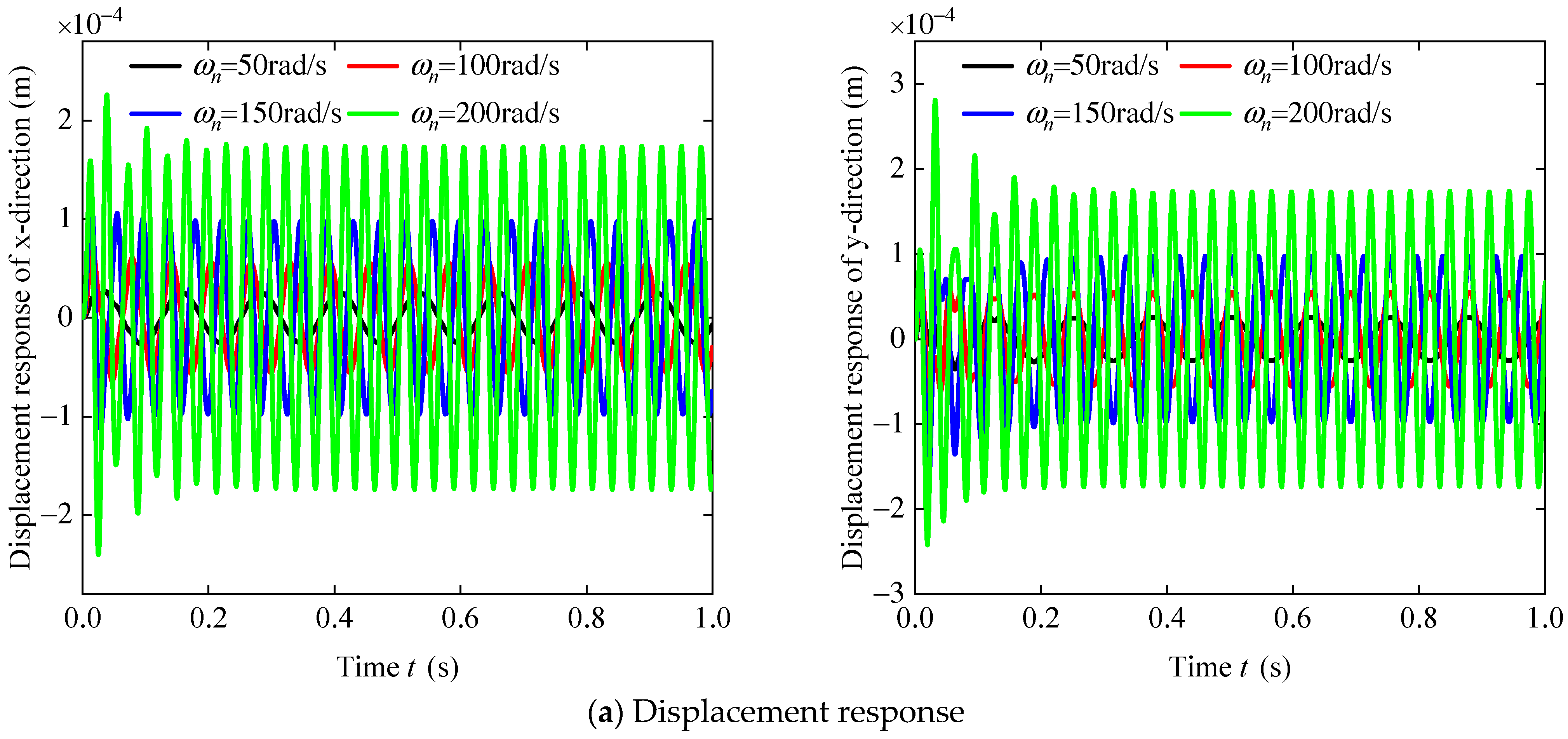
3.3. The Dynamic Response of the Bearing–Rotor–Disk System

The mathematical model of the bearing–rotor–disk system was verified according to the above discussion, and the optimal structure form of DRACBBs under complex external loads was determined. The dynamic response of the bearing–rotor–disk system was solved by employing the Newmark-β method. The total time and time step size were selected as 1 s and 0.001 s. The structural parameters of the bearing–rotor–disk system were introduced in the above discussion. The axial force Fz of the DRACBBs was selected as 5000 N for the following discussion. The coupling node of the rotor and disk was chosen as the research object, and the dynamic response results for the bearing–rotor–disk system under unbalanced excitation are shown in Figure 14.
As shown in Figure 14, the variation tendency of the dynamic response, including the displacement response, velocity response and acceleration response, of the bearing–rotor–disk system is consistent, first oscillating and then remaining stable with time. Meanwhile, it is evident that the dynamic response level increases significantly with increasing rotating angular velocity ωn = 2π/Ωs, and the dynamic response of the y-direction is slightly larger than the dynamic response of the x-direction. We can conclude that the vertical vibration response of the bearing–rotor–disk system is more significant. To further describe the dynamic response of the bearing–rotor–disk system, FFT of the dynamic response of was carried out, and the results can be seen in Figure 15.
As shown in Figure 15, the dynamic response of the rotor–bearing–disk system presents two resonant peaks in the frequency range of 0–200 Hz. One resonant peak is caused by the rotor–disk system, and the other is caused by the DRACBBs. The resonant peak caused by the bearing–rotor system increases and moves to a higher frequency with an increase in the angular velocity ωn. However, the resonant peak caused by the DRACBBs increases and its location remains constant with an increase in the angular velocity ωn. It is worth mentioning that the resonant frequency caused by the DRACBBs is a multiple of the resonant frequency caused by the rotor–disk system.

4. Conclusions

This paper presents a general mathematical model of a bearing–rotor–disk system for systematically analyzing the dynamic responses of DRACBBs under complex external loads and the dynamic responses of bearing–rotor–disk systems under unbalanced excitation. Some representative conclusions are given as follows:
(1)
Back-to-Back DRACBBs under complex external loads have greater dynamic performance when compared with the other structural forms of DRACBBs.
(2)
The dynamic response of the y-direction of the bearing–rotor–disk system is more significant than the dynamic response of the x-direction when the rotating speed of the bearing–rotor–disk system is increased.
(3)
There are two resonant peaks, which are caused by the rotor–disk system and the DRACBBs, respectively, and their variation tendencies are different. The above research can offer a theoretical basis for the design and manufacture of power systems in aero-engines.

Author Contributions

Conceptualization, Q.W.; methodology, T.L. and Z.L.; software, H.L.; validation, H.Z.; formal analysis, H.L.; investigation, H.Z.; resources, H.L.; data curation, Z.L.; writing—original draft preparation, H.Z.; writing—review and editing, T.L.; visualization, Z.L.; supervision, Q.W.; funding acquisition, Q.W. All authors have read and agreed to the published version of the manuscript.

Funding

This research received no external funding.

Data Availability Statement

Data are contained within the article.

Acknowledgments

The authors would like to thank the anonymous reviewers for their very valuable comments.

Conflicts of Interest

Authors Haibiao Zhang and Haijian Liu were employed by the company Aero Engine Corporation of China. The remaining authors declare that the research was conducted in the absence of any commercial or financial relationships that could be construed as a potential conflict of interest.

Nomenclature

SymbolDescription
αoThe free contact angle
NThe number of single rolling elements
ψjThe azimuth
DThe diameter of the ball
DmThe pitch diameter of double-row angular contact ball bearings
ci, coThe clearances between the ball and the inner and outer raceways
c1The judgement coefficient of left and right rows of angular contact ball bearings
c2The judgement coefficient of the structural form
fi, foThe inner and outer raceway curvature coefficients
ri, roThe inner and outer raceway curvature radii
BThe width of double-row angular contact ball bearings
Ki, KoThe contact stiffness coefficients of the inner and outer raceway
ωnThe angular velocity of the rotor

Appendix A

The contact deformation coefficient of the DRACBBs:
K m = 2.15 × 10 5 × ρ m × δ m * 3 / 2 m = i , o
δ i * = 327.6145 + 1883.338 × F p i 3798.1121 × ( F p i ) 2 + 3269.6154 × ( F p i ) 3 1026.96 × ( F p i ) 4 δ o * = 327.6145 + 1883.338 × F p o 3798.1121 × ( F p o ) 2 + 3269.6154 × ( F p o ) 3 1026.96 × ( F p o ) 4
F p i = 1 f i + 2 r 1 r / 4 1 f i + 2 r 1 r ;   F p o = 1 f o 2 r 1 + r / 4 1 f o 2 r 1 + r
f i = r i / D ;   f o = r o / D ;   r = D / D m cos α o
ρ i = p 11 i + p 12 i + p 21 i + p 22 i ;   ρ o = p 11 o + p 12 o + p 21 o + p 22 o
p 11 i = p 21 i = p 11 o = p 21 o = 2 / D p 12 i = 2 D r 1 r ;   p 12 o = 2 D r 1 + r p 22 i = 1 / r i ;   p 22 o = 1 / r o

Appendix B

The mass, gyroscopic and stiffness matrices of the beam element:
M r e = ρ r A r l e a 0 0 0 c 0 b 0 0 0 d 0 0 a 0 c 0 0 0 b 0 d 0 0 0 0 1 3 0 0 0 0 0 1 6 0 0 0 0 c 0 g 0 0 0 d 0 f 0 0 c 0 0 0 g 0 d 0 0 0 f 0 0 0 0 0 0 J r 3 A r 0 0 0 0 0 J r 6 A r b 0 0 0 d 0 a 0 0 0 c 0 0 b 0 d 0 0 0 a 0 c 0 0 0 0 1 6 0 0 0 0 0 1 3 0 0 0 0 d 0 f 0 0 0 c 0 g 0 0 d 0 0 0 f 0 c 0 0 0 g 0 0 0 0 0 0 J r 6 A r 0 0 0 0 0 J r 3 A r
a = 13 35 + 7 10 ϕ r + 1 3 ϕ r 2 + 6 5 r g l e 2 1 + ϕ r 2
b = 9 70 + 3 10 ϕ r + 1 6 ϕ r 2 6 5 r g l e 2 1 + ϕ r 2
c = 11 210 + 11 120 ϕ r + 1 24 ϕ r 2 + 1 10 1 2 ϕ r r g l e 2 l e 1 + ϕ r 2
d = 13 420 + 3 40 ϕ r + 1 24 ϕ r 2 1 10 1 2 ϕ r r g l e 2 l e 1 + ϕ r 2
f = 1 140 + 1 60 ϕ r + 1 120 ϕ r 2 + 1 30 + 1 6 ϕ r 1 6 ϕ r 2 r g l e 2 l e 2 1 + ϕ r 2
g = 1 105 + 1 60 ϕ r + 1 120 ϕ r 2 + 2 15 + 1 6 ϕ r + 1 3 ϕ r 2 r g l e 2 l e 2 1 + ϕ r 2
K e = h 0 0 0 i 0 h 0 0 0 i 0 0 h 0 i 0 0 0 h 0 i 0 0 0 0 A r E r l e 0 0 0 0 0 A r E r l e 0 0 0 0 i 0 j 0 0 0 i 0 k 0 0 i 0 0 0 j 0 i 0 0 0 k 0 0 0 0 0 0 G r J r l e 0 0 0 0 0 G r J r l e h 0 0 0 i 0 h 0 0 0 i 0 0 h 0 i 0 0 0 h 0 i 0 0 0 0 A r E r l e 0 0 0 0 0 A r E r l e 0 0 0 0 i 0 k 0 0 0 i 0 j 0 0 i 0 0 0 k 0 i 0 0 0 j 0 0 0 0 0 0 G r J r l e 0 0 0 0 0 G r J r l e
G r e = 0 p 0 q 0 0 0 p 0 q 0 0 p 0 0 0 q 0 p 0 0 0 q 0 0 0 0 0 0 0 0 0 0 0 0 0 q 0 0 0 s 0 q 0 0 0 w 0 0 q 0 s 0 0 0 q 0 w 0 0 0 0 0 0 0 0 0 0 0 0 0 0 0 p 0 q 0 0 0 p 0 0 0 0 p 0 0 0 q 0 p 0 0 0 q 0 0 0 0 0 0 0 0 0 0 0 0 0 q 0 0 0 w 0 0 0 0 0 s 0 0 q 0 w 0 0 0 q 0 s 0 0 0 0 0 0 0 0 0 0 0 0 0 0
p = 6 5 r g 2 l e 2 1 + ϕ r 2 ;   q = 1 10 1 2 ϕ r r g 2 l e 2 1 + ϕ r 2 ;   s = 2 15 + 1 6 ϕ r + 1 3 ϕ r 2 r g 2 1 + ϕ r 2 ;   w = 1 30 + 1 6 ϕ r 1 6 ϕ r 2 r g 2 1 + ϕ r 2
r g = I r A r ;   κ r = 6 1 + υ 7 + 6 υ
A r = π 4 D r 2 ;   G r = E r 2 1 + υ ;   I r = π 64 D r 4 ;   ϕ r = 12 E r I r κ r A r G r l e 2 ;   J = π 32 D r 4

References

  1. Parmar, V.; Saran, V.H.; Harsha, S. Effect of an unbalanced rotor on dynamic characteristics of double-row self-aligning ball bearing. Eur. J. Mech.-A/Solids 2020, 82, 104006. [Google Scholar] [CrossRef]
  2. Li, Y.; Luo, Z.; Liu, J.; Ma, H.; Yang, D. Dynamic modeling and stability analysis of a rotor-bearing system with bolted-disk joint. Mech. Syst. Signal Process. 2021, 158, 107778. [Google Scholar] [CrossRef]
  3. Ebrahimi, R.; Ghayour, M.; Khanlo, H.M. Nonlinear dynamic analysis and experimental verification of a magnetically supported flexible rotor system with auxiliary bearings. Mech. Mach. Theory 2018, 121, 545–562. [Google Scholar] [CrossRef]
  4. Singh, S.; Tiwari, R. Model based identification of crack and bearing dynamic parameters in flexible rotor systems supported with an auxiliary active magnetic bearing. Mech. Mach. Theory 2018, 122, 292–307. [Google Scholar] [CrossRef]
  5. Saeed, N.A.; Kandil, A. Lateral vibration control and stabilization of the quasiperiodic oscillations for rotor-active magnetic bearings system. Nonlinear Dyn. 2019, 98, 1191–1218. [Google Scholar] [CrossRef]
  6. Ma, H.; Li, H.; Zhao, X.; Niu, H.; Wen, B. Effects of eccentric phase difference between two discs on oil-film instability in a rotor–bearing system. Mech. Syst. Signal Process. 2013, 41, 526–545. [Google Scholar] [CrossRef]
  7. She, H.; Li, C.; Tang, Q.; Wen, B. The investigation of the coupled vibration in a flexible-disk blades system considering the influence of shaft bending vibration. Mech. Syst. Signal Process. 2018, 111, 545–569. [Google Scholar] [CrossRef]
  8. Chiu, Y.J.; Chen, D.Z. The coupled vibration in a rotating multi-disk rotor system. Int. J. Mech. Sci. 2011, 53, 1–10. [Google Scholar] [CrossRef]
  9. Yang, C.H.; Huang, S.C. The influence of disk’s flexibility on coupling vibration of shaft–disk–blades systems. J. Sound Vib. 2007, 301, 1–17. [Google Scholar] [CrossRef]
  10. Chiu, Y.J.; Yang, C.H. The coupled vibration in a rotating multi-disk rotor system with grouped blades. J. Mech. Sci. Technol. 2014, 28, 1653–1662. [Google Scholar] [CrossRef]
  11. Chiu, Y.J.; Huang, S.C. The influence on coupling vibration of a rotor system due to a mistuned blade length. Int. J. Mech. Sci. 2007, 49, 522–532. [Google Scholar] [CrossRef]
  12. Ding, Q.; Leung, A.Y.T. Numerical and experimental investigations on flexible multi-bearing rotor dynamics. J. Vib. Acoust. 2005, 127, 408–415. [Google Scholar] [CrossRef]
  13. Li, C.; She, H.; Tang, Q.; Wen, B. The effect of blade vibration on the nonlinear characteristics of rotor–bearing system supported by nonlinear suspension. Nonlinear Dyn. 2017, 89, 987–1010. [Google Scholar] [CrossRef]
  14. Ma, H.; Lu, Y.; Wu, Z.; Tai, X.; Wen, B. Vibration response analysis of a rotational shaft–disk–blade system with blade-tip rubbing. Int. J. Mech. Sci. 2016, 107, 110–125. [Google Scholar] [CrossRef]
  15. Ma, H.; Li, H.; Niu, H.; Song, R.; Wen, B. Numerical and experimental analysis of the first-and second-mode instability in a rotor-bearing system. Arch. Appl. Mech. 2013, 84, 519–541. [Google Scholar] [CrossRef]
  16. Wang, L.; Cao, D.Q.; Huang, W. Nonlinear coupled dynamics of flexible blade–rotor–bearing systems. Tribol. Int. 2010, 43, 759–778. [Google Scholar] [CrossRef]
  17. Lu, Z.; Liu, L.; Wang, X.; Ma, Y.; Chen, H. Dynamic modeling and bifurcation analysis of blade-disk rotor system supported by rolling bearing. Appl. Math. Model. 2022, 106, 524–548. [Google Scholar] [CrossRef]
  18. Zhou, S.T.; Chiu, Y.J.; Yu, G.F.; Yang, C.-H.; Huang, H.-W.; Jian, S.-R. An assumed mode method and finite element method investigation of the coupled vibration in a flexible-disk rotor system with lacing wires. J. Mech. Sci. Technol. 2017, 31, 577–586. [Google Scholar] [CrossRef]
  19. Zhao, S.; Zhang, L.; Zhu, R.; Han, Q.; Qin, Z.; Chu, F. Modeling approach for flexible shaft-disk-drum rotor systems with elastic connections and supports. Appl. Math. Model. 2022, 106, 402–425. [Google Scholar] [CrossRef]
  20. Tuzzi, G.; Schwingshackl, C.; Green, J. Cross-disc coupling in a flexible shaft–disc assembly in presence of asymmetric axial–radial bearing supports. J. Sound Vib. 2022, 527, 116826. [Google Scholar] [CrossRef]
  21. Mereles, A.; Cavalca, K.L. Modeling of multi-stepped rotor-bearing systems by the continuous segment method. Appl. Math. Model. 2021, 96, 402–430. [Google Scholar] [CrossRef]
  22. Mereles, A.; Cavalca, K.L. Mathematical modeling of continuous multi-stepped rotor-bearing systems. Appl. Math. Model. 2021, 90, 327–350. [Google Scholar] [CrossRef]
  23. Khorrami, H.; Rakheja, S.; Sedaghati, R. Vibration behavior of a two-crack shaft in a rotor disc-bearing system. Mech. Mach. Theory 2017, 113, 67–84. [Google Scholar] [CrossRef]
  24. Al-Solihat, M.K.; Behdinan, K. Force transmissibility and frequency response of a flexible shaft–disk rotor supported by a nonlinear suspension system. Int. J. Non-linear Mech. 2020, 124, 103501. [Google Scholar] [CrossRef]
  25. Xiang, L.; Hu, A.; Hou, L.; Xiong, Y.; Xing, J. Nonlinear coupled dynamics of an asymmetric double-disc rotor-bearing system under rub-impact and oil-film forces. Appl. Math. Model. 2016, 40, 4505–4523. [Google Scholar] [CrossRef]
  26. Li, Z.; Wang, Q.; Qin, B.; Shao, W. Vibration characteristic analysis of flexible rotor-bearing system subjected to external combined loads. Eur. J. Mech.-A/Solids 2022, 96, 104688. [Google Scholar] [CrossRef]
  27. Wang, P.; Yang, Y.; Ma, H.; Xu, H.; Li, X.; Luo, Z.; Wen, B. Vibration characteristics of rotor-bearing system with angular misalignment and cage fracture: Simulation and experiment. Mech. Syst. Signal Process. 2022, 182, 109545. [Google Scholar] [CrossRef]
  28. Cao, H.; Niu, L.; Xi, S.; Chen, X. Mechanical model development of rolling bearing-rotor systems: A review. Mech. Syst. Signal Process. 2018, 102, 37–58. [Google Scholar] [CrossRef]
  29. Petersen, D.; Howard, C.; Sawalhi, N.; Ahmadi, A.M.; Singh, S. Analysis of bearing stiffness variations, contact forces and vibrations in radially loaded double row rolling element bearings with raceway defects. Mech. Syst. Signal Process. 2015, 50, 139–160. [Google Scholar] [CrossRef]
  30. Gunduz, A.; Singh, R. Stiffness matrix formulation for double row angular contact ball bearings: Analytical development and validation. J. Sound Vib. 2013, 332, 5898–5916. [Google Scholar] [CrossRef]
  31. Zhang, J.; Fang, B.; Hong, J.; Wan, S.; Zhu, Y. A general model for preload calculation and stiffness analysis for combined angular contact ball bearings. J. Sound Vib. 2017, 411, 435–449. [Google Scholar] [CrossRef]
  32. Yang, L.; Xu, T.; Xu, H.; Wu, Y. Mechanical behavior of double-row tapered roller bearing under combined external loads and angular misalignment. Int. J. Mech. Sci. 2018, 142, 561–574. [Google Scholar] [CrossRef]
  33. Ai, S.; Wang, W.; Wang, Y.; Zhao, Z. Temperature rise of double-row tapered roller bearings analyzed with the thermal network method. Tribol. Int. 2015, 87, 11–22. [Google Scholar] [CrossRef]
  34. Gunduz, A.; Dreyer, J.T.; Singh, R. Effect of bearing preloads on the modal characteristics of a shaft-bearing assembly: Experiments on double row angular contact ball bearings. Mech. Syst. Signal Process. 2012, 31, 176–195. [Google Scholar] [CrossRef]
  35. Xu, T.; Yang, L.; Wu, W.; Han, Y.; Xu, E.; Wang, K. The stiffness characteristics analysis of the duplex angular contact ball bearings based on a comprehensive multi-degree-of-freedom mathematical model. Appl. Math. Model. 2022, 106, 601–626. [Google Scholar] [CrossRef]
  36. Xu, T.; Yang, L.; Wu, W.; Wang, K. Effect of angular misalignment of inner ring on the contact characteristics and stiffness coefficients of duplex angular contact ball bearings. Mech. Mach. Theory 2020, 157, 104178. [Google Scholar] [CrossRef]
Figure 1. The structural forms of DRACBBs.
Lubricants 12 00441 g001
Figure 2. The coordinate systems of a DRACBB.
Lubricants 12 00441 g002
Figure 3. The geometric location relationship of a DRACBB.
Lubricants 12 00441 g003
Figure 4. The geometric description of a two-node beam element.
Lubricants 12 00441 g004
Figure 5. The geometric description of the disk.
Lubricants 12 00441 g005
Figure 6. The dynamic model of the bearing–rotor–disk system.
Lubricants 12 00441 g006
Figure 7. The comparison results of the contact force of DRACBBs.
Lubricants 12 00441 g007
Figure 8. The contact characteristics of DRACBBs under purely axial force Fz.
Lubricants 12 00441 g008
Figure 9. The dynamic stiffness of DRACBBs under purely axial force Fz.
Lubricants 12 00441 g009
Figure 10. The contact characteristics of DRACBBs under purely radial force Fx and Fy.
Lubricants 12 00441 g010
Figure 11. The dynamic stiffness of DRACBBs under radial force Fx and Fy.
Lubricants 12 00441 g011
Figure 12. The contact characteristics of DRACBBs under torque Mx and My.
Lubricants 12 00441 g012
Figure 13. The dynamic stiffness of DRACBBs under torque Mx and My.
Lubricants 12 00441 g013
Figure 14. The dynamic responses of the bearing–rotor–disk system under unbalanced excitation.
Lubricants 12 00441 g014aLubricants 12 00441 g014b
Figure 15. FFT of the dynamic response of the bearing–rotor–disk system.
Lubricants 12 00441 g015aLubricants 12 00441 g015b
Table 1. The structural parameters of DRACBB 7010AC/DB.
Structural ParameterParameter UnitValue
Dmm9
N (single row)-18
αo°25
EMPa2.06 × 105
ν-0.3
ρkg/m37850
rimm4.635
romm4.725
cimm0
comm0
Bmm32
Dmmm65
Table 2. The comparison results of the natural frequency of the rotor–disk system under static conditions.
OrderF-FS-SC-C
PresentANSYSPresentANSYSPresentANSYS
1119.0118.925.725.748.348.2
2188.9188.895.295.1121.7121.6
3373.4372.5312.7311.9148.2148.0
4746.4745.4585.3584.7374.2373.0
5925.8925.9665.1665.0665.1665.0
61220.21215.5724.6723.6752.0749.9
71371.81358.01098.21092.3927.6925.8
81475.51447.61371.81358.01216.41210.2
91744.91732.21475.51447.61610.61609.0
101829.51828.61592.11582.71737.11722.6
Table 3. The comparison results of the natural frequency of the rotor–disk system under non-static conditions.
OrderNatural Frequency50 rad/s100 rad/s150 rad/s200 rad/s
PresentANSYSPresentANSYSPresentANSYSPresentANSYS
1Backward48.25448.20648.25348.20448.25248.20348.25148.201
Forward48.25548.20948.25648.2148.25648.21248.25748.213
2Backward121.725121.64121.725121.64121.725121.64121.725121.64
Forward121.725121.64121.725121.64121.725121.64121.725121.64
3Backward148.104147.78147.961147.57147.817147.36147.673147.14
Forward148.391148.2148.534148.42148.677148.63148.820148.84
4Backward374.095372.9374.031372.8373.968372.69373.904372.59
Forward374.222373.11374.286373.21374.349373.32374.413373.42
Disclaimer/Publisher’s Note: The statements, opinions and data contained in all publications are solely those of the individual author(s) and contributor(s) and not of MDPI and/or the editor(s). MDPI and/or the editor(s) disclaim responsibility for any injury to people or property resulting from any ideas, methods, instructions or products referred to in the content.

