1. Introduction
Various types of grooves are used in mechanical components such as bearings and valves to improve their lubrication characteristics. Creating a specific pattern on the lubricating surface to improve lubrication characteristics is known as surface texturing, so in a broader sense, groove machining is related to surface texturing. Therefore, the improvement in lubrication characteristics achieved through surface texturing and groove machining share many similarities. These grooves have various shapes and perform multiple functions. Most notably, grooves serve as channels for the smooth delivery of lubricants or act as reservoirs for storing lubricants [
1]. Additionally, in spool valves, grooves are used to prevent hydraulic lock caused by circumferential pressure imbalances by helping to mitigate these imbalances [
2]. Groove machining also reduces frictional losses caused by fluid viscosity through decreasing the contact area on the lubricating surface. Additionally, grooves can be applied in various forms to contact seals [
2,
3,
4]. Moreover, grooves can also enhance the load-bearing capacity [
5,
6]. In practice, grooves are often added to a design with a single function in mind, but sometimes, they are designed with two or more purposes in mind. For example, the grooves applied to bushes lubricated with grease in construction machinery not only serve as channels for grease supply but are also designed to enhance the load-bearing capacity. In other words, in actual mechanical systems, the design of any grooves should be determined based on the lubrication characteristics required by the machine. However, this study focuses not on the lubrication of a specific mechanical system but on how grooves trap wear particles. Foreign materials, such as wear particles or externally introduced particles, can cause damage to lubrication systems, like hydraulic valves, as shown in
Figure 1 [
7]. Therefore, to prevent three-body abrasive wear caused by foreign materials, research on the capture effect of grooves is necessary.
This trapping effect of grooves is used extensively in the chemical and mining industries and can be observed in applications such as slurry transport, sewer systems, irrigation channels, and natural processes like river dynamics [
8,
9].
Kaushal et al. [
10,
11,
12,
13] studied the use of sediment trapping structures, known as in-vert traps, as a method to reduce sediment accumulation in drainage systems and irrigation channels. These traps are installed at the base of sewer pipes or channels to collect and store sediments. They also provided results from both 3D and 2D analyses of the in-vert trap using the Volume of Fluid (VOF) method. Hubbell [
14] introduced pit traps to address the issue of traditional bed-load sampling devices interfering with the flow. Chebbo et al. [
15] proposed that invert traps, commonly referred to as bed-load sediment traps, offer a more effective solution. Bachoc [
16] suggested placing invert traps at potential sedimentation points to capture larger particles from the flow. He determined that a gradual slope alone does not guarantee sedimentation, as other factors such as the channel’s shape, including any sudden changes in its geometry, and the conditions of the downstream flow also play a role. Ashley et al. [
17] provided an extensive review on managing sediment in combined sewers. They believed that a method to evaluate sediment buildup in sewer systems under different operational conditions was needed alongside recommendations for the most effective control strategy. Buxton et al. [
18] compared experimentally and computationally obtained trap efficiencies for invert traps with rectangular configurations and central openings of 2.25, 4.5, and 9 cm. In hydraulic systems, such as spool valves, it has been reported that the width and depth of the grooves applied to the spool must be at least 10 times greater than the clearance, while the sides of the grooves should be machined vertically [
19]. Kaushal et al. [
11] investigated the influence of lid thickness and particle shape factor on predicting the particle trap efficiency of inverted traps. Next, the existing research on the numerical analysis techniques that have been used to investigate grooves was examined. Most analyses primarily use the DPM (Discrete Phase Model) [
8,
13,
20,
21,
22,
23] or DEM (Discrete Element Model) [
24,
25,
26,
27,
28,
29] based on Computational Fluid Dynamics (CFD) to study the flow of two phases: liquid and solid. In CFD, the VOF (Volume of Fluid) method is the fundamental basis of the analysis. The DPM is primarily used in simulations where discrete particles interact with a continuous fluid phase. In this approach, the fluid flow is modeled using standard CFD methods, while the behavior of particles, such as droplets or bubbles, is tracked separately using the Lagrangian method. The DPM focuses on how particles exchange momentum, energy, and mass with the fluid but does not consider interactions between individual particles. This model is particularly suited for scenarios where the particle volume fraction is relatively low compared to the fluid volume, typically less than 10%. On the other hand, the DEM is designed to simulate the interactions between discrete particles themselves, as well as their interactions with surrounding boundaries. It also uses the Lagrangian approach, but with a focus on calculating the forces, collisions, and mechanical interactions between particles. The DEM is capable of detailed analysis of particle–particle interactions, including factors like contact forces and friction. This makes it particularly useful for studying granular flows, powders, and other systems where particle interactions are significant and the particle volume fraction can be high. In other words, while DPM is effective for systems with sparse particles where particle interactions are minimal, DEM is more appropriate for dense particle systems where the interactions between particles play a crucial role [
30,
31,
32].
Research on the trap effect of grooves has mostly been applied to sewer systems, while only a limited number of studies have focused on lubrication systems such as hydraulic valves or bearings [
33,
34,
35,
36]. In real-world lubrication systems, failures often occur due to abrasive wear from particles or external substances in filters or bearings. To prevent such issues, it is necessary to study the trap effect of grooves in systems with small clearances.
This study evaluated the particle trapping effect of grooves as an important design approach to prevent three-body abrasive wear caused by wear particles or foreign materials contained in lubricants. In particular, it conducted the first investigation into the particle trapping effect of grooves based on the cross-sectional shape of the groove and the Reynolds number in lubrication systems with small clearances. This study introduces a method to improve lubrication performance in sliding lubrication systems by trapping wear particles through grooves. It is the first to numerically evaluate the particle trapping effectiveness of grooves in sliding lubrication systems. The analysis aimed to interpret the results based on the flow patterns and particle trajectories within the grooves. Furthermore, by presenting the particle trapping effectiveness of grooves as a function of the Reynolds number and groove cross-sectional shapes, this study seeks to provide design guidelines for groove applications in real application systems based on these analytical findings.
2. Numerical Model and Analysis
In this study, the analysis was performed using COMSOL, version 6.0. The CFD module was used for flow analysis, while the DPM module was used for particle behavior analysis. In terms of the interaction between fluid and solid particles in DPM, a one-way coupling method was used, where the fluid affects the solid particles, but the solid particles do not influence the fluid. This analysis was performed for a transient state. For the boundary conditions of the particles, a reflect condition was applied at the wall surfaces, while an escape condition was applied at both boundaries, i.e., at the inlet and outlet, where the particles are allowed to exit the system. In addition, the low Re
k-
ε turbulence model was applied to accurately describe turbulent flow within the groove. A 3D sliding bearing was chosen as the analysis model, as shown in
Figure 2. The shaft moves translationally with a velocity of
u, while the sleeve remains stationary. The pressure at the inlet of the bearing is 50 kPa, and the pressure at the outlet of the bearing is 20 kPa. In this analysis, a pressure difference between the inlet and outlet was applied to more efficiently identify the characteristics. When identical pressure conditions were applied on both sides, it took a significantly longer time to reach a steady state. The shaft has a radius of 50 mm, and the length of the bearing is 220 mm. The shaft moves concentrically within the bearing, with a clearance of 100 µm. The groove is located 50 mm away from the inlet. The groove is machined in a ring around the circumference of the shaft. This study does not include the effect of the groove position. However, placing the groove at a certain distance from both ends of the bearing, rather than close to the ends, is advantageous for particle trapping. This is because the pressure differential in the lubricant film near the ends reduces the particle trapping efficiency in those areas. In lubrication systems, bearings generally operate under conditions of eccentricity and tilting. However, in the present numerical analysis, a concentric state was assumed. This approach was chosen to exclude the effects of eccentricity and tilting, allowing for a focused evaluation of the influence of the Reynolds number and groove shape on the system’s performance.
The cross-sectional shape and dimensions of the various grooves used in the analysis are shown in
Figure 3. The groove shape was proposed based on previous research on grooves in spool valves and findings from studies on the removal of small stone-like debris in mines. The cross-sectional shapes include square (type-1), isosceles triangle (type-2), U-shape (type-3), and a combination of trapezoidal and rectangular shapes (type-4). The widths and depths of all grooves were uniformly set to 5 mm. A variation where a radius with a curvature of 1 mm was applied to both upper edges of the square cross-sectional-shaped groove was also analyzed. This groove shape is referred to as type-1-r. This model was chosen in order to investigate whether the application of curvature at the upper edges of the groove affects particle capture.
Figure 3 also shows the meshes applied to the groove cross-sections. Depending on the shape of the groove, both rectangular and hybrid meshes were utilized. Although there are slight variations based on the cross-sectional shape of a particular groove, approximately 2900 to 3000 elements were applied to the 2D cross-section of the groove. To accurately calculate the flow and particle trajectories in the groove area, a dense mesh was applied, as shown in
Figure 4. The 180 meshes are applied in the circumferential direction, resulting in an overall mesh count of approximately 532,000 to 600,000. The properties of the solid particles and lubricant used in the analysis are shown in
Table 1. The solid particles contained in actual lubricants come in various shapes and sizes. In this analysis program, however, only spherical particles were considered. The solid particles are made of iron and have a size of 10 µm. Furthermore, the absolute viscosity and density of SAE 20 grade lubricant at 50 °C were applied.
This paper evaluates the trapping effect of the grooves based on their cross-sectional shape, the Reynolds number (
Re) of the lubricant, and the curvature of the edges. The Reynolds number is given by Equation (1), where
η and
ρ represent the absolute viscosity [Pa·s] and the density [kg/m
3] of the lubricant, respectively, while
u,
c, and
d denote the velocity of the shaft, clearance, and depth of the groove, respectively. The no-slip condition is applied at the shaft boundary, meaning that the velocity of the shaft and the lubricant are the same. The analysis was performed for three Reynolds numbers: 69.05, 690.5, and 6905. For instance, when the Reynolds number is 69.05,
u is 0.312 m/s.
The flow pattern within the groove is expected to change with variations in the Reynolds number, which will also likely affect the trapping effect of the groove. Therefore, the study examined how the trapping efficiency was affected not only by changes in the cross-sectional shape of the groove but also by the variations in the Reynolds number. Additionally, in the case of the square cross-section groove, the trapping effect of the groove was analyzed with and without adding curvature to the two upper edges.
In this study, the Low Reynolds number k-ε turbulence model was applied for a Reynolds number of 6905. The relevant equations are provided below. “Low Reynolds number” refers to the region close to the wall where viscous effects dominate.
The turbulent viscosity (
μT) is modeled in Equation (2).
where
k,
ε, and
Cμ indicate energy, turbulent dissipation rate, and model constant, respectively. In the analysis, the
Cμ is 0.09.
The transport equation for
k is presented in Equation (3).
where
ρ,
t,
u, and
σk represent density, time, velocity of fluid, and model constant, respectively.
In the analysis,
σk is 1.0. In addition, the production term is defined in Equation (4).
The transport equation for
ε is defined in Equation (5).
where
σε,
Cε1, and
Cε2 are model constants, with values of 1.3, 1.44, and 1.92, respectively.
The model constants in Equations (2)–(5) are determined from experimental data [
37].
3. Numerical Results and Discussion
3.1. Particle Trapping Effect of Grooves with Various Cross-Sectional Shapes
The trapping effect of the grooves was examined according to changes in groove shape and Reynolds number. First, the most common groove with a rectangular cross-section was investigated. Although various rectangular grooves with various width-to-height ratios could be studied, in this analysis, the trapping effect of the grooves was compared and evaluated based on changes in the cross-sectional shape while the width and height of the cross-section were kept equal. That is, the rectangular cross-section grooves investigated in this study are square.
Figure 5 shows the initial particle distribution and streamlines for square grooves with three different Reynolds numbers. “Initial” refers to the time period under 0.1 s, during which the particles are evenly distributed. The color of the particles represents their velocity. When approximately 500 particles are dispersed, they are uniformly distributed along the streamlines at the initial stage. Although it is difficult to assess the trapping effect of the particles based on Reynolds number during this initial phase, differences in the streamlines within the groove due to variations in the Reynolds number can be observed. In the figure, the red “+” marks indicate the center of large vortices. As the Reynolds number increases, the center of the large vortex shifts toward the centroid of the square, and the vortex shape becomes more circular [
38,
39]. From the initial stage, as the Reynolds number increases, it can be observed that more particles are distributed toward the outer region of the groove. When the Reynolds number is small, at 69.05, no small eddy currents develop near the lower edge. However, as the Reynolds number increases, two distinct small eddy currents form at the lower edges.
The trapping effect of particles was evaluated based on the shape of the groove and Reynolds number. In this context, the particle distributions were examined at the stage when the flow had stabilized, as shown in
Figure 6. The physical time for each stage to occur varies depending on the Reynolds number. Ultimately, the time required for stabilization also differs according to the Reynolds number and cross-sectional shape. For example, within the square groove, the time taken for stabilization was 100 s, 10 s, and 20 s for Reynolds numbers of 69.05, 690.5, and 6905, respectively. However, within the isosceles triangle groove, the stabilization times were approximately 100 s, 3 s, and 0.2 s for Reynolds numbers of 69.05, 690.5, and 6905, respectively.
Examining the streamlines in the isosceles triangle groove at the lowest Reynolds number, we can see two large vortices are formed. As the Reynolds number increases, an additional small eddy current forms at the bottom of the groove. At a Reynolds number of 6905, an additional small eddy current also develops in the upper right corner. When the groove cross-sectional shape is U-shaped, only one large vortex is formed, with no small eddy currents present. In three groove shapes—square, isosceles triangle, and U-shape—the center of the large vortex moves closer to the center of the groove as the Reynolds number increases. Moreover, in the groove with a combined trapezoid and rectangle shape, when the Reynolds number is low at 69.05, a single large vortex is formed along with very small eddy currents at the corners of the rectangular section. However, when the Reynolds number is 690.5 or 6905, a large vortex develops in each of the trapezoidal and rectangular sections. Also, when the Reynolds number is high at 6905, additional small eddy currents form in the lower corner and the upper right corner.
The particle trapping effect of the grooves was analyzed after the flow had reached a stabilized state, as shown in
Figure 6. Even in grooves with the same cross-sectional shape, the degree of particle trapping varies significantly depending on the Reynolds number. When the groove cross-section is square, a lower Reynolds number results in a relatively high number of particles being trapped. However, as the Reynolds number increases, the inertial forces of the fluid increase, causing particles to escape from the groove. In other words, as the Reynolds number increases, the groove’s particle trapping efficiency significantly decreases. In the isosceles triangle-shaped groove, two additional vortices form at the top and bottom of the groove as the Reynolds number increases. As a result, at the highest Reynolds number, no particle trapping occurs in the large vortex formed at the top. However, some particles remain trapped in the vortex and small eddy currents located at the bottom. This indicates that the formation of large and small vortices affects particle trapping within a groove. In the case of the U-shaped groove, as previously mentioned, only one large vortex exists at the lowest Reynolds number. As the Reynolds number increases, the center of the vortex moves toward the center of the groove. Since no additional vortices or eddy currents are generated, even at a Reynolds number of 690.5, the groove fails to trap particles. The U-shaped cross-section is streamlined; this facilitates smooth fluid flow but makes it unsuitable for particle trapping. In the groove with a combined trapezoid and rectangle shape, it appears that more particles are trapped when the Reynolds number is low compared to when it is high. At the Reynolds number of 6905, there are no particles trapped in the trapezoidal section, but some particles remain trapped in the lower rectangular section due to the vortex and small eddy currents that have formed there. Similar to the isosceles triangle cross-section, the trapezoid–rectangle combination also forms two or more distinct vortices, with the particles being effectively trapped by the vortices formed in the lower section.
The particle trapping effect of grooves in sliding bearings has been found to be related to the formation of vortices and small eddy currents within the groove. In particular, cross-sectional shapes that create two or more vortices and generate significant small eddy currents at the corners are effective for particle trapping. When a large main vortex and separate smaller vortices are present, the larger flow within the groove becomes somewhat separated, making it more difficult for particles to escape due to being caught in the small eddy currents at the bottom corners. This results in an enhanced particle trapping effect. Additionally, the Reynolds number significantly influences the trapping efficiency. As the Reynolds number increases, the increased inertial forces of the fluid make it easier for particles to escape from the groove, leading to reduced particle trapping efficiency.
3.2. Particle Trapping Effect of Groove Corners’ Curvature Radius
Most grooves used in lubrication systems have a rectangular cross-section. Reference materials for spool valves suggest that the sides of the groove should be machined vertically [
19]. However, for various reasons, small curvatures can sometimes form at the top edges. In this context, an investigation was conducted to determine whether the application of curvature at the top edges of the groove affects its particle trapping efficiency. To compare, larger curvature radii were applied intentionally, rather than relying on unintended curvatures that occur due to machining issues. Therefore, the particle trapping effect was examined by comparing two cases: one where curvature was applied to the upper edge on both sides of a square groove cross-section and another where no curvature was applied.
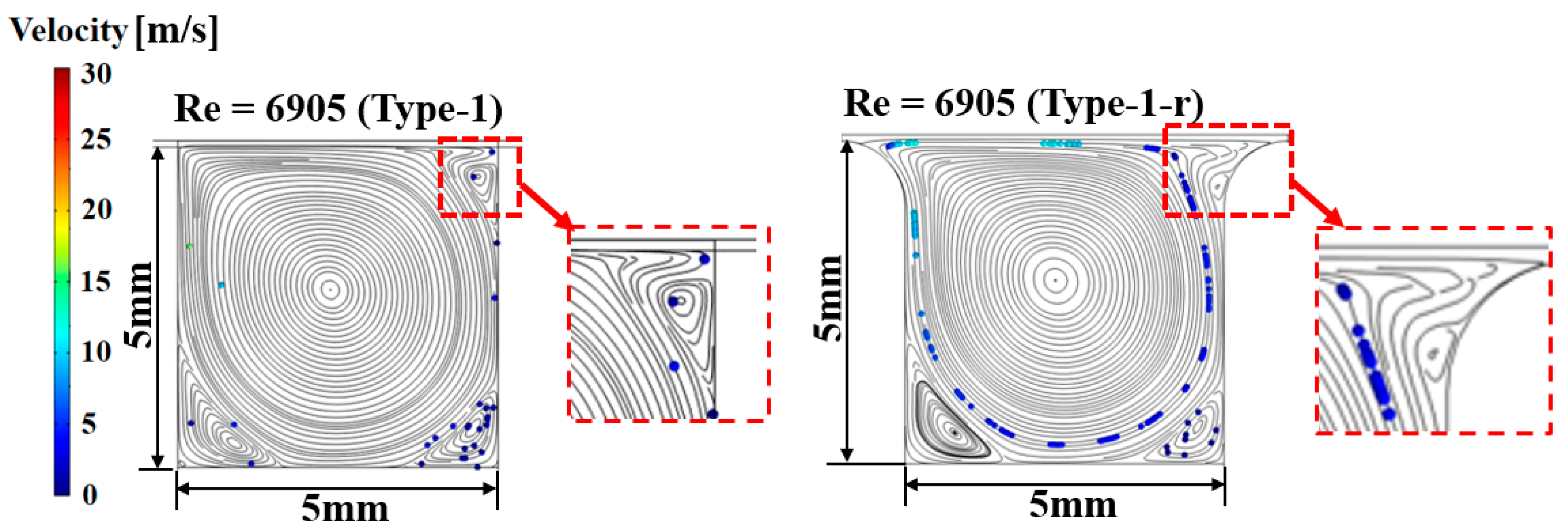
Figure 7 shows the streamlines inside the groove when curvature is applied to the top edges of the groove with Reynolds numbers of 69.05 and 690.5. In the figure, the color represents the velocity of the fluid. From this figure, it is clear that applying curvature to the corners significantly alters the streamline patterns in those areas. Notably, in the areas marked with red dotted lines, the streamlines can be seen turning and flowing around the expanded region at the top edge where curvature is applied. In
Figure 8, when the Reynolds number is as high as 6905, the streamlines near the corners show significant changes compared to the original perfectly square type-1 design. As a result, in the type-1-r groove, particles remain trapped even within the large vortex; this is in contrast to the type-1 configuration where hardly any particles are trapped by the large central vortex. It appears that the curvature applied to the top edges of the groove reduces the connectivity between the streamlines near the top edge and those in the adjacent gap created by adding curvature, preventing the escape of particles from the groove. Although the specific outcomes may vary depending on the radius of curvature at the corners, applying curvature to the groove corners can potentially compensate for the reduced particle trapping efficiency observed at higher Reynolds numbers.
In this research, the particle trapping effect of various grooves was examined. The trapping efficiency of a groove varies depending on its cross-sectional shape and the Reynolds number of the lubricant. Our results suggest that the groove cross-section should be designed to generate as many vortices and small eddy currents as possible. Among the various cross-sectional shapes of the grooves tested, the isosceles triangle (type-2) and the shape combining a trapezoid and a rectangle (type-4) were relatively effective in trapping particles. Additionally, as the Reynolds number increases, particle trapping becomes more challenging, even under the same cross-sectional conditions. It was also confirmed that applying curvature to the top edges of rectangular grooves could enhance their particle trapping efficiency when the Reynolds number increases.
In addition, it is anticipated that the effects of streamline flow and particle trapping will vary depending on the depth and width of the groove. On top of this, the number and position of the grooves should also be considered as factors influencing the particle trapping efficiency of a system. Given the time constraints, conducting a comprehensive analysis of all possible variations of groove design and operating conditions is challenging. Therefore, this analysis aims to signpost appropriate design directions for grooves that more effectively trap particles by investigating a single groove in a representative sliding bearing. The research methodology regarding the particle trapping effects of grooves is believed to contribute to preventing three-body abrasive wear in various lubrication systems. Although the scope of this study is limited, it is still significant. Consequently, it is essential to pursue not only further analytical research but also experimental studies in the future.
4. Conclusions
This study focused on improving lubrication performance by preventing three-body abrasive wear caused by foreign particles in lubrication systems using grooves. In addition to supplying lubricating oil, grooves serve various functions, such as alleviating pressure imbalances. This research specifically aimed to enhance lubrication performance by investigating how certain design choices can improve the ability of grooves to trap foreign particles. The particle trapping effect of various grooves was evaluated according to their cross-sectional shape and to changes in the Reynolds number of the lubricant. Four types of groove cross-sections, each with the same width and depth, were proposed and assessed: square (type-1), isosceles triangle (type-2), U-shape (type-3), and a combination of trapezoid and rectangle (type-4). Additionally, a variation of type-1 with curvature applied to the upper edges (type-1-r) was also considered. The analysis results revealed that designing a groove to generate multiple vortices and small eddy currents leads to effective particle trapping. Hence, cross-sectional shapes, like the isosceles triangle or a combination of trapezoid and rectangle shapes, outperform more streamlined designs, like the U-shaped groove, in particle trapping efficiency. As the Reynolds number increases, the inertial forces of the fluid increase, reducing the particle trapping effect of the groove. Therefore, particle trapping through grooves is more effective at lower Reynolds numbers. It was also confirmed that applying curvature to the top edges of a square groove can help compensate for the reduced trapping efficiency of perfectly square grooves at higher Reynolds numbers. In this study, the particle trapping effect of grooves, which are applied as a measure to prevent three-body abrasive wear, was evaluated based on the Reynolds number and groove cross-sectional shape. This research is expected to contribute to improving lubrication characteristics as a design approach for preventing three-body abrasive wear. In other words, designing grooves suitable for trapping particles can prevent wear caused by particles and ultimately enhance the reliability of the product. Therefore, this study provides a novel numerical proposal demonstrating that the application of grooves in lubrication systems with narrow gaps can enhance the particle trapping effect. This approach can be utilized as a design strategy to improve lubrication characteristics in various lubrication systems. In this regard, this study is novel not only in its significance but also in presenting a new design approach.
Although this study did not cover all possible groove designs and operating conditions, it offers valuable design guidelines for improving the particle trapping efficiency in lubrication systems. Further analytical research, along with experimental studies for validation, will be necessary and is planned for the future. Specifically, additional research is needed on the continuous application of grooves, differences in design strategies between rotational and linear reciprocating motion, and the effect of the aspect ratio of grooves.


