1. Introduction
Tribological principles have been applied in various modern mechanical elements, such as bearings, cams, and gears, to transmit power and motion through contact interfaces. Lubricants are intentionally utilized to enhance the wear and abrasion resistance of these surfaces, thereby prolonging their operational life. It is important to note that elastic surface deformation and increased lubricant viscosity due to high pressure play significant roles in the formation of a separating film. This type of lubrication, which takes such effects into account, is commonly referred to as Elastohydrodynamic Lubrication (EHL) [
1,
2,
3,
4]. Extensive studies have been conducted to achieve accurate predictions of the pressure distribution and film thickness profiles in EHL scenarios [
5,
6,
7,
8,
9].
For effective operation, adequate inlet oil supply is necessary to achieve fully flooded lubrication. However, traditional lubrication methods employed in mechanical systems—such as splash lubrication for cylinder liner–piston ring pairs and gear pairs—often fail to deliver the precise amount of oil required, potentially leading to insufficiently oiled areas [
10,
11]. Additionally, relative motion between surfaces can cause oil to be flung off, resulting in lubricant starvation in the lubricated region [
12]. When lubrication starvation occurs, the lubricant only partially fills the surface gap [
13,
14,
15,
16], and the EHL model may over-evaluate the separating abilities of the oil film.
Even when lubricant supply is adequate, the mating surfaces may not be completely separated under overloaded or ultra-low entraining conditions. The surface asperities at some local areas may penetrate the lubricant film, and the solid direct contacts partially carry out the loading [
17,
18,
19]. This lubrication regime is known as mixed lubrication and can lead to excessive heat, friction, and vibration, ultimately causing damage to the frictional surfaces [
20]. It has long been recognized that lubrication profiles under such conditions can be governed by a unified solution system, and extensive models have been proposed previously [
21,
22,
23]. Specifically, the solutions of pressure distribution and film thickness generated by the model are sensitive to initial conditions, particularly in the mixed lubrication regime, which may can lead to convergence issues and thereby potentially limit the solution reliability when subjected to varying operational parameters.
Numerous studies have aimed to predict lubrication conditions by considering asperity contacts under starved oil scenarios [
14,
24]. However, elastically induced deformation may not accurately capture the material response to contact loading when the local stress intensity exceeds the material’s strength. Meanwhile, Kehl et al. [
25] found that damage resulting from plastic deformation can affect residual stress, leading to crack initiation and spalling of material. Plastic deformation is regarded as one of the most frequent causes of material failure and must be considered in the reliability analysis of mechanical systems [
26,
27]. Semi-analytical methods have provided flexible approaches to identifying plastic zones and their evolution [
28,
29,
30,
31,
32,
33]. Moreover, plastic deformation damage can influence lubrication conditions; however, the impact of plasticity on lubrication behavior under starved conditions has not been thoroughly discussed.
In this study, we present a mixed lubrication model that incorporates the coupled effects of inlet oil starvation and material plasticity. The dimensional Reynolds equation is discretized using appropriately selected schemes to cover a wide range of lubrication regimes, and the boundary profiles are enforced by the inlet oil supply conditions. The plastic eigenstrains are iteratively determined by the return mapping algorithm and the residual deformation is considered as a source of contribution to the lubricant film. The developed model has potential applications in analyzing lubrication behaviors of functional mechanical elements and may provide valuable insights into material responses under various lubrication conditions.
2. Solution Method
Starved lubrication or starvation limits the formation of the lubricant film. Pressure can only be generated at certain regions, and the film within such areas totally fills the interfacial gap [
24]. In some non-pressurized areas, the contact surfaces may restrict the further formation of the film and the space between them is fully filled, but in others, the thickness of the lubricant film depends on the starvation conditions.
In order to involve all the lubrication conditions in one unified system, Jacobsson and Flodeberg [
34] proposed a fractional film content, which is defined as the ratio between the lubricant film and the gap of contact elements, given as
A mass conservative algorithm was introduced by Elrod [
13] to account for the lubricant continuum with the density modified as
. Accordingly, the Reynolds equation can be written as
in which
and
are the entraining velocities along the
x- and
y-axes, respectively. The viscosity
describes the shear behavior of the lubricant, and an effective viscosity can be properly selected depending on its non-Newtonian property [
26].
Based on such assumptions, the fractional film content is enforced as
, where the film fully fills the interfacial gap, and the film thickness can be calculated by
with surface roughness
and
involved. The thickness where the film partially fills the gap can be determined by
where
can be properly obtained according to the pressure and film thickness.
Physically, the film should not be below zero thickness. However, under some server conditions, for example, if the lubricant entrains at an extremely low speed or the system is overloaded, the solids are in direct contact with each other at some local areas [
35], and Equations (3) and (4) may result in a negative thickness. At such areas, the hydrodynamic pressure ceases to act for the load balance, and the lubrication profiles are thus governed by a reduced Reynolds equation [
26]:
Similarly, the shear flow of the Reynolds equation is cut off when a startup or shutdown process with
is concerned, and the pressure flow is totally balanced by the squeeze effect due to the normal motion of contact surfaces. It should be further noted that the squeeze term under steady operation may not be necessarily involved for load balancing but should always be considered for transient processes [
5].
Local surface elastic deformation
is determined by the integral effects of the generated pressure within the computational domain
, given as
The viscosity in the present study is assumed to follow the Barus pressure–viscosity relationship,
and the Dowson–Higginson pressure–density relationship is employed for the density variation [
36]:
Traditionally, the technique of the optimum similarity analysis is employed to reduce the number of independent parameters presented in the above equations [
37]. However, such treatment may complicate the expression of the original Reynolds equation. In particular, when elliptical contact is concerned, the Hertzian parameters have to be determined for normalization. Furthermore, when it comes to a startup or shutdown process, one may have to deal with a special state of
, and the traditional normalization may no longer be applicable. In the present study, the original Reynolds equation in its dimensional form is discretized directly with the unit MPa for pressure, mm for length and s for time. The computational domain is meshed into
patches.
For a point contact, the pressure at the boundaries is enforced as
, and the second-order central differential scheme is employed to discretize the pressure flow terms, while the second-order backward scheme is used to discretize the shear and squeeze flow terms [
38]. The discrete equations along the
y-direction can be expressed in the following form:
with coefficients
,
,
and
derived from the discretization of the Reynolds equation. The pressure can then be iteratively determined line by line, and solutions of all discrete lines
together describe the pressure distributions. It should be noted that the above equation can also be formulated along the
x-direction due to the symmetry of the Reynolds equation.
The above algorithm procedure is also applicable for three-dimensional (3D) line contact. The extended line in this study is assumed along the y-direction. Although the pressure at the boundaries and may not be the same as that under ambient conditions, the solution matrix of Equation (9) can still lead to a relatively accurate description of the lubrication profiles with an acceptable error. The boundary condition of enables the relationships of and , where . Such a model can be used to analyze the lubrication behaviors of gear pairs.
Once the profiles of the pressure and film thickness are determined, the fractional film content can be determined accordingly. If the local area is pressurized,
is set to be 1 automatically; otherwise,
is calculated based on the discretization schemes employed, and in the present study, the following equation is used for such calculation:
where
. It should be noted that the above equation may result in
, in which case
is enforced, or
, in which case
is assigned. The discontinuity of
at the boundary between the pressurized region and the starved region, known as the meniscus, has long been recognized.
The iterative process is performed until the convergence of the distributions of the pressure and fractional film content. It has been noted that the solution convergence is sensitive to the initial value, especially under mixed lubrication regimes. In order to reduce such sensitivity and improve the convergence, the solution is initialized as the value derived from the analysis of a dry contact. The corresponding solution set is given as
A modified Conjugate Gradient Method (CGM) is employed for such analysis; for details, refer to [
5,
39].
A depth of
is supposed for the stress analysis with
nodes equally spaced. The stresses at a given time step can be obtained by the summation of the influences of all meshed elements, calculated by
where
is the coefficient vector correlated to the stress components at the element
caused by the unit pressure at the patch
.
The material may yield as long as the local von Mises equivalent stress
exceeds its strength
. The
J-2 criterion for material yield initiation is given as [
40]
where
and the deviatoric stress
. The plastic strain accumulation always follows the volume conservative condition. Once the trial plastic domain is identified, the actual increment of the effective plastic strain returns the
J-2 yield function to zero and can be determined by the function
, where the effective accumulative plastic strain
and the plastic strain
. A return mapping algorithm is employed in the present study, and it has shown its robustness in achieving an accurate description of the plastic behaviors.
The residual displacements may influence the topographies of the surfaces and thus perturb the pressure profile, which may, in turn, lead to a different distribution of plastic eigenstrains. Such a mutually dependent process thus forms an additional loop besides the procedure for the pressure and fractional film content. It is noted that the residual strains accumulate with the increase in the load and it is suggested to increase the load gradually for the sake of solution accuracy. The iterative process is performed until the desired load is achieved and the solution then proceeds to the next time step.
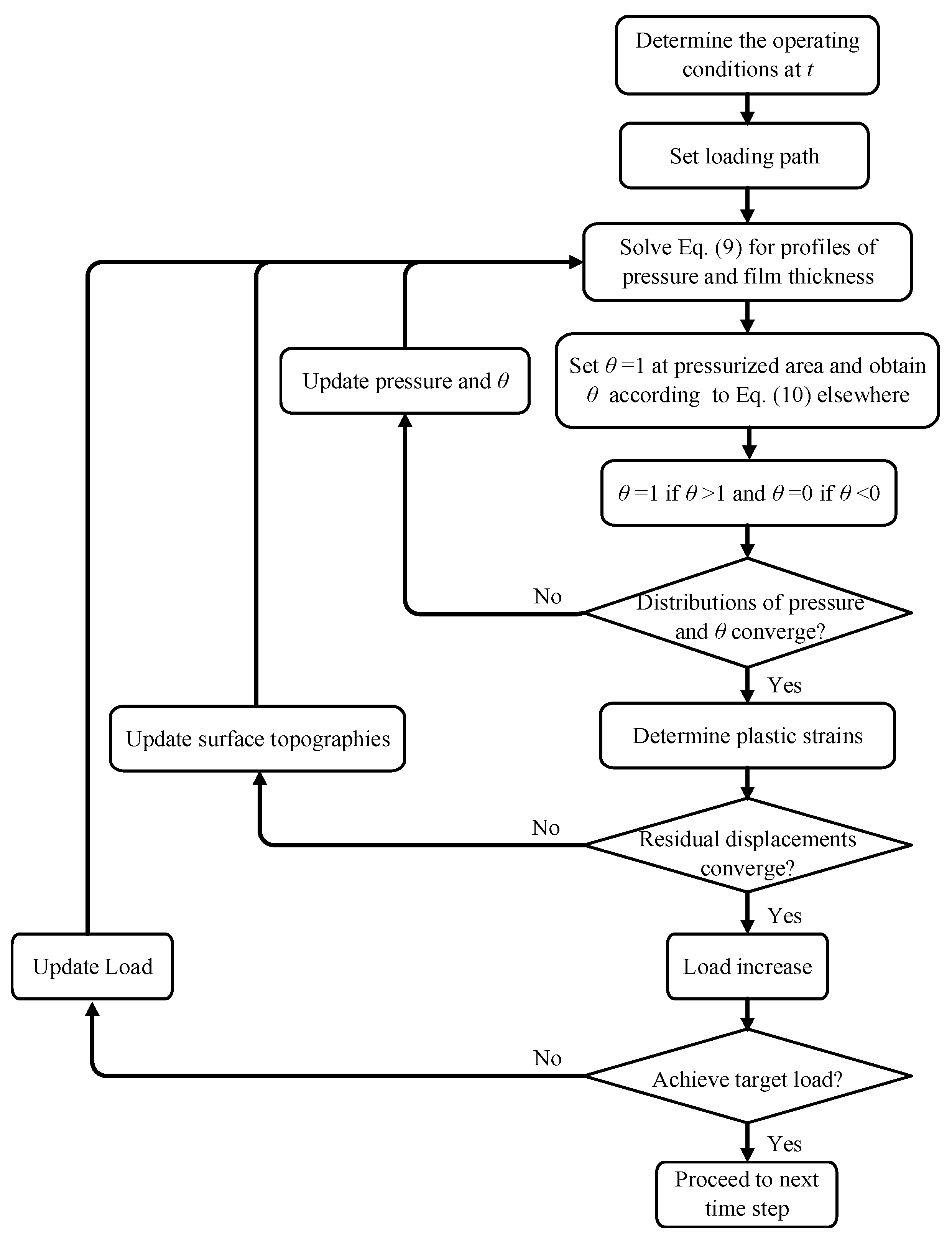
Figure 1 shows the flowchart of the computational process.
3. Results and Discussion
The model is firstly adopted for the point contact of purely elastic materials, and a comparison is made between the results from the present model and those reported by Wijnant [
15] to verify the solution of starved lubrication. The Moes parameters and
are selected to be the same as those employed in the reference. The lubricant oil used in this study is a mineral oil, and necessary parameters are listed in
Table 1. The computational domain is fixed in a domain
with
patches equally spaced, where
represents the Hertzian radius.
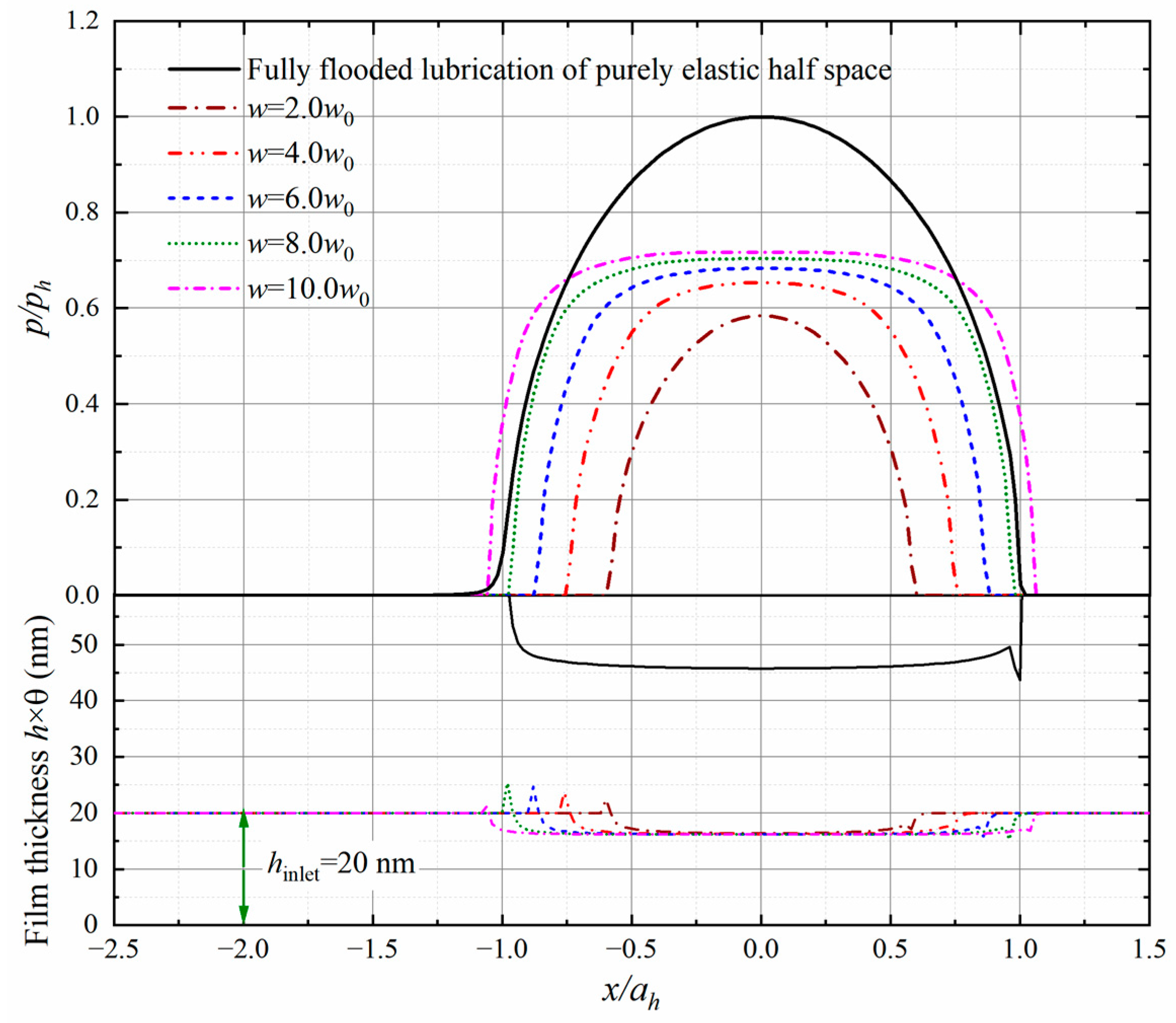
Figure 2 depicts the profiles of pressure and film thickness normalized by
and
when the oil entrains at various levels, where
stands for the reduced radius of the curvature, calculated by
, and
is the Hertzian pressure. The oil inlet level
denotes the central film thickness when a fully flooded lubrication condition is assumed. It appears that the film jumps from the initial thickness of the inlet oil to a higher level at the meniscus position due to the dramatical change in the fractional film content. A sufficient inlet oil supply may potentially enable the film to separate the contact interfaces and thus reduce the frictional tribology. Good agreement can be found between the results from the present model and those reported in reference [
14].
The model is then used to investigate the lubrication profiles in the initial state of a startup process with the lubricant entrainment velocities of
.
Figure 3 shows the pressure and lubricant thickness for the inlet oil with a thickness of
. The developed algorithm in the present study can lead to a rapid convergence of the solution if the contact area is fully flooded [
5,
22]; however, when the starved condition is concerned, especially for a very thin layer of inlet oil, it is suggested to decrease the length of the time step to achieve a reasonable solution. Generally, the normalized time interval should be less than the grid lengths normalized by the Hertzian radius. An even smaller value is preferred to enhance accuracy, but this may increase computational costs to achieve convergence. Our previous studies discussed the selection of the time interval in detail. Refer to [
41] for details. In this study, we found that a time step of 0.02 ms offers high computational efficiency while effectively preserving both computational accuracy and stability based on our numerical experiments. It is observed that no lubricant is entrapped within the pressurized area while the film thickness remains at the same value as the gap where
and
or the same as
where
. The pressure appears to be consistent with that of the Hertzian contact. The lubrication in the line contact also leads to such profiles along the velocity direction in such a specified state.
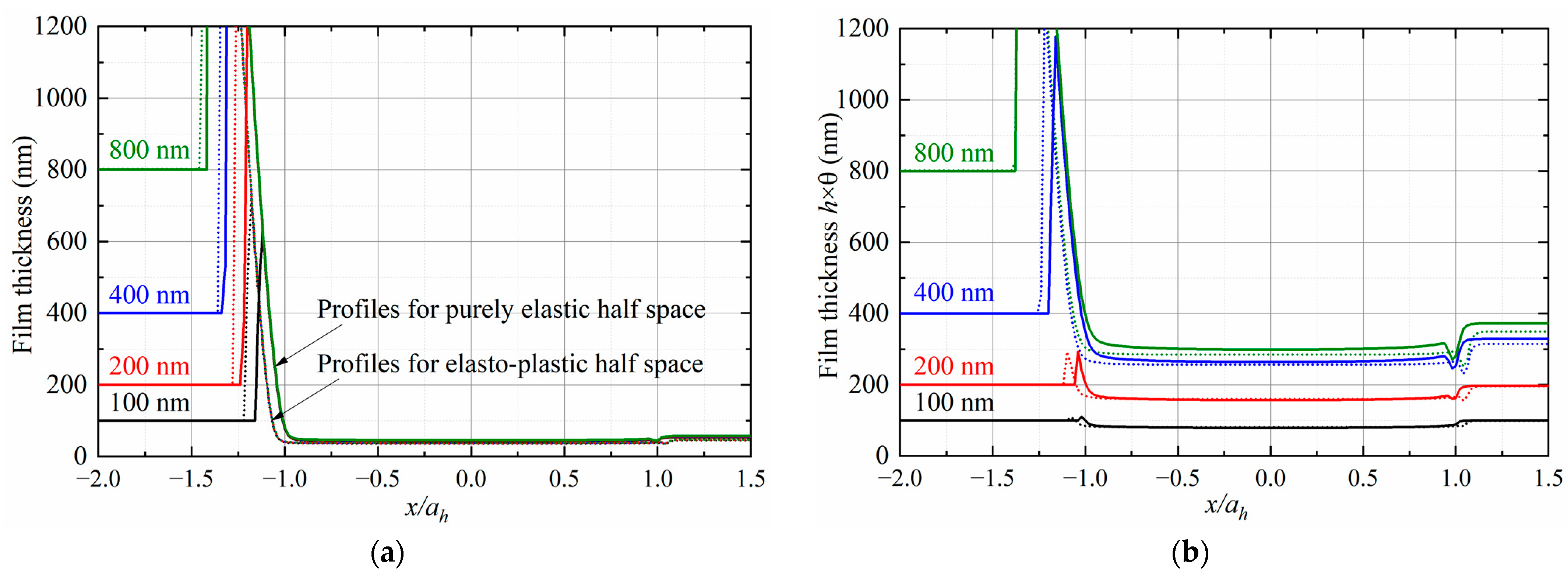
Solutions of a series of cases in 3D line contact are presented in
Figure 4. The domain is set within
and the load is fixed as
. The inlet oil is assumed to entrain at a velocity of
with a thickness of
. It is observed that the fractional film content along the extended direction remains as a constant. The meniscus position moves to the inlet zone as the inlet oil layer becomes thicker and the pressurized area is enlarged. The pressure is consistent with that of the Hertzian contact in a severely starved condition,
in this case, and shows the classical characteristics of fully flooded lubrication with a relatively rich supply of the inlet oil.
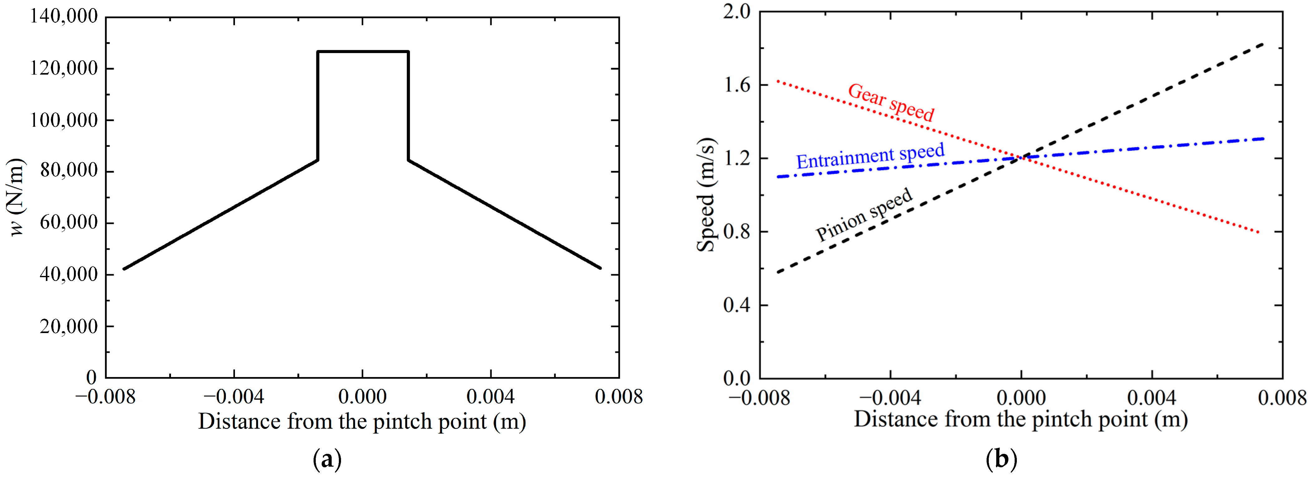
The starvation model has potential for application in the lubrication evaluation of mechanical elements when the lubricant oil is not sufficiently supplied. Depending on the geometries of the involved elements, the elliptical or line contact model can be selected accordingly. In the present study, the 3D line contact model is adopted to investigate the lubrication performance of a spur gear pair with the contact line extended in
, where
is the semi-width of the Hertzian contact under the reference load
at the pitch point. The gear data and properties of the lubricant are listed in
Table 2. The load per unit length is assumed to follow the trapezoidal function [
42]. As shown in
Figure 5a, it increases gradually in the first few steps as the target pair of gears is engaged in mesh and reaches its maximum value when this pair carries out the load all on its own. The load remains as a constant for a while and then reduces as the other pair takes action to deliver the power. The surface velocities depend on the radii of the contact curvatures and are plotted in
Figure 5b.
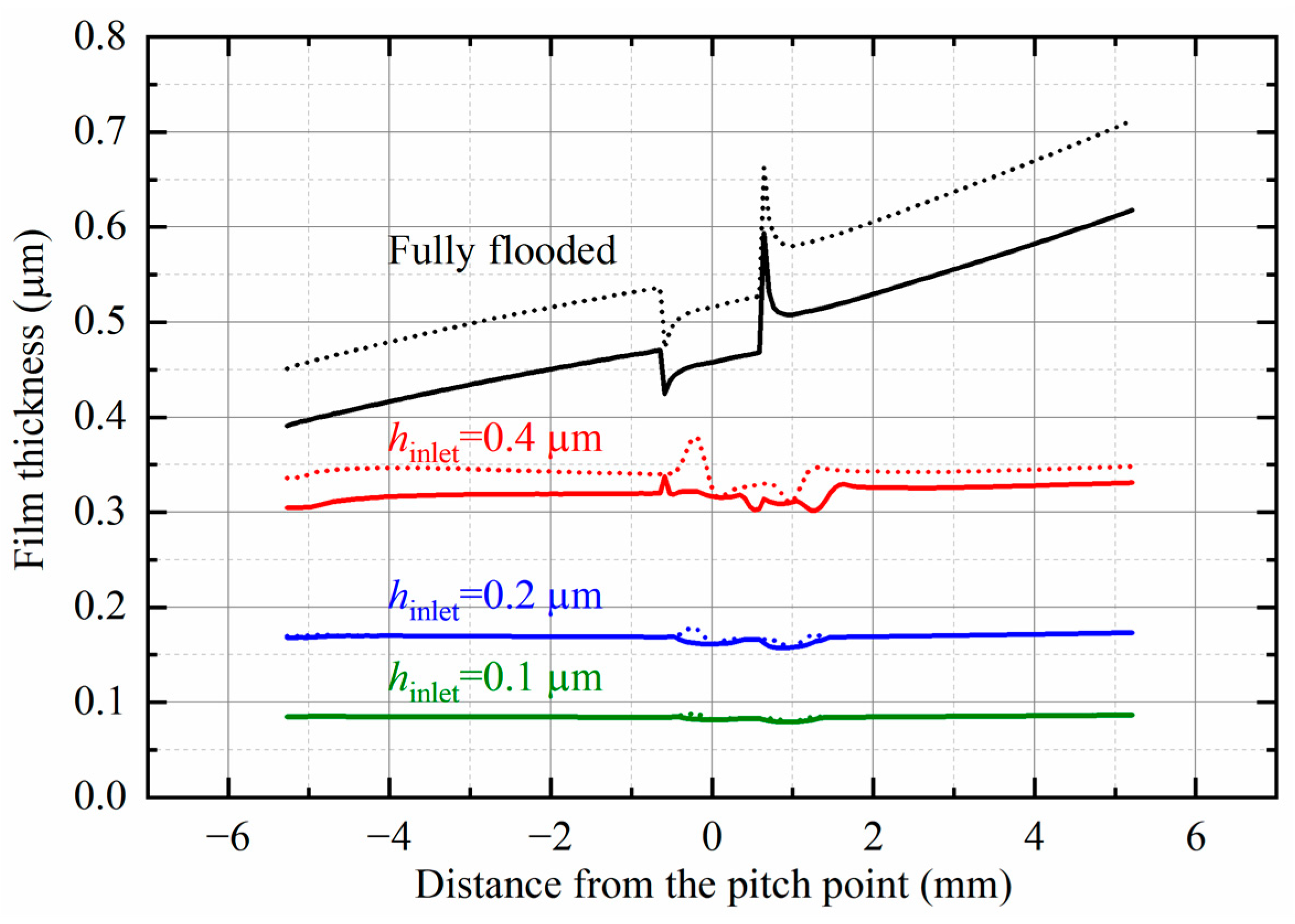
The variations in the minimum film thickness (solid lines) and central film thickness (dotted lines) along the line of action are shown in
Figure 6. It is observed that when the contact area is fully flooded, the film drops at the transitional position from two engaged pairs to one pair and jumps when a reverse procedure proceeds. When the inlet oil is relatively rich,
in this case, the film at the center is always thicker than the minimum value. However, as the starved condition becomes severe,
in this case, the thinnest film appears at the center except for several points around the transitional position. It should be noted that the initial solution is derived from a steady operating condition, and the film profiles under various starvation regimes are plotted in
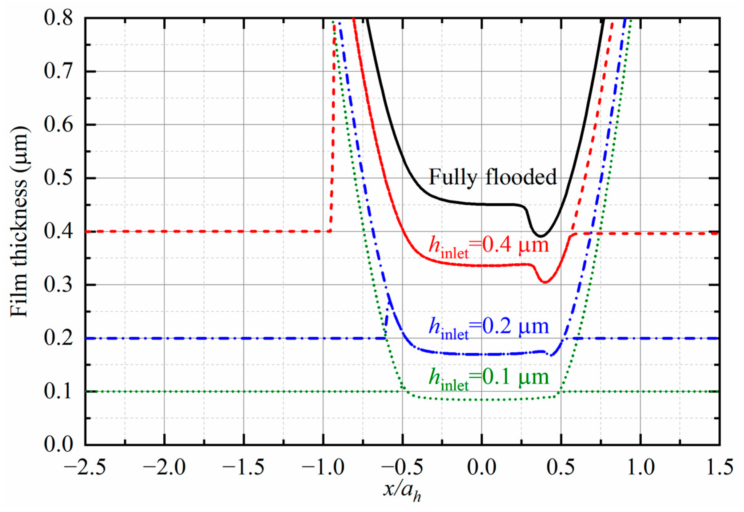
Figure 7.
The pressure may induce an intensive stress field and thus lead to the yield of materials. In this study, materials are assumed to follow the elastic–perfectly plastic law. Solutions of the point contact at the entraining velocities of
are compared with those of dry contact to verify the present model, and the material parameters and contact conditions are listed in
Table 3. The load is increased to the target value gradually at an equal increment of
.
Figure 8 shows the pressure at various loading steps within
along the
x-axis and
along the
y-axis. It is observed that the material behaves elastically under a light load,
in this case, and the pressure thus agrees well with that of the Hertzian contact. Along with the loading increase, the profiles appear to be relatively flat, and good consistency can be found with those reported previously [
43,
44]. It is noted that an improper initial solution may probably induce extra errors under boundary or mixed lubrication regimes and result in unexpected fluctuation of the lubrication profiles along the relaxation direction. The CGM-based algorithm developed in the present study has shown its ability to minimize such errors, and the solutions along both principal directions appear to be smooth in shape. The effect of the entrainment velocity on the lubrication profiles is shown in
Figure 9. A pressure spike is observed at a high entraining velocity
and the film thickness increases with the velocity.
A starvation condition with an oil inlet thickness of
is then studied, and the entraining velocity is fixed at
. The profiles, plotted in
Figure 10, show that the pressure increases with the load in a similar pattern as that of
Figure 8 or a dry contact due to the extremely thin inlet oil. The meniscus position where the film jumps to a higher level moves gradually away from the center. The thickness there is determined by the local lubrication condition and is not necessarily increased with the load. The film thickness is dramatically reduced compared with the solution of fully flooded lubrication with a purely elastic half space involved. Although no pressure spike occurs, cavitation phenomena occur anyway. The central film almost remains as a constant at various loading steps.
Figure 11a shows the profiles of film thickness under various starvation conditions at
(solid lines for purely elastic half space and dotted lines for elasto-plastic half space). It is concluded that the inlet oil thickness may influence the profile of fractional film content, but the central and minimum film thickness appears on the same scale due to the relatively low entrainment. The eigenstrains within plastic regions may induce permanent deformation on the surface and thus result in a larger pressurized area. The profiles of pressure and film thickness at the entrainment velocity of
are plotted in
Figure 11b. A thicker film is observed to separate the contact surfaces, but a higher entrainment may decrease the film thickness at the meniscus position and increase the thickness when the lubricant flows out of the contact area. Such effects will probably not influence the transmission behavior of mechanical components but may largely affect the formation of lubrication film for the further process of operating systems.
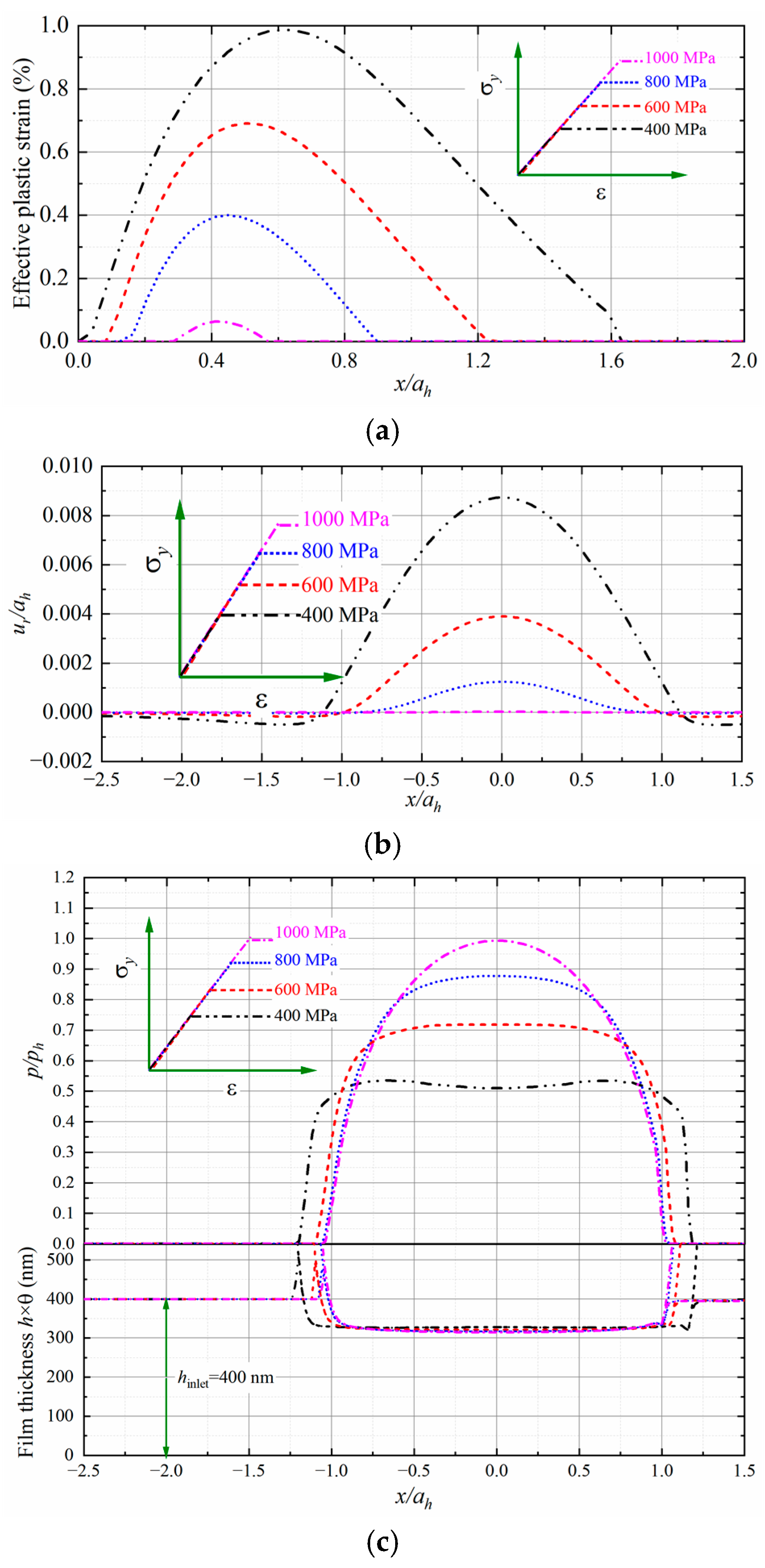
The effect of the yield strength is investigated in the following case.
Figure 12a plots the effective plastic strain along the
z-axis for the half space yielding at
with the lubricant entraining at
. The film thickness of the inlet oil is fixed as
. When subject to the same loading condition, the body with small yield stress may produce intensive plastic strains within a large region and a deep dent is thus formed permanently, shown as
Figure 12b. Such effects may lead to a large pressurized area with
, but the central and minimum film thickness is hardly changed, as shown in
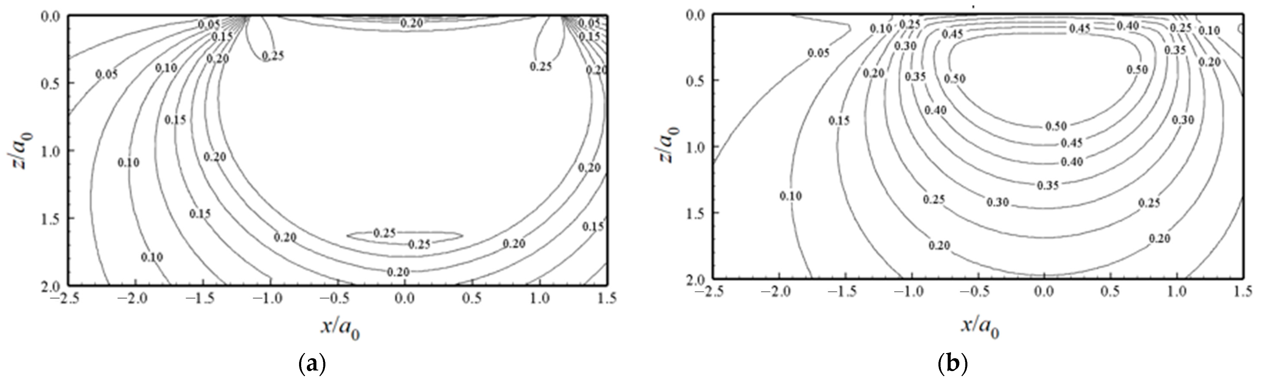
Figure 12c. It should be noted that the computational domain should be large enough to involve all the elements where plasticity may potentially occur. The stress contours for
are compared in
Figure 13. The stresses may not occur beyond the yield strength, and an enhanced half space induces a higher stress level.
4. Conclusions
In this study, the non-normalized discretization of the Reynolds equation is developed to formulate a solvable matrix for the lubrication problem. Such a technique is applied to the point and line contacts according to the geometry characteristics of contact bodies. A modified CGM is integrated into the model to obtain the initial value of the solution, and such an algorithm may reduce the solution sensitivity and improve the solution convergence. The model is capable in a wide range of lubrication regimes, from boundary lubrication to fully hydrodynamic lubrication. The profiles of pressure distribution and fractural film thickness are iteratively obtained based on the enforced boundary conditions at the inlet zone. The elasto-plastic response of materials is then taken into account and its effects on starvation are revealed.
Solutions of a point contact under various starvation conditions are compared with those reported previously and good agreement is found. The pressure conditions in the initial state of a startup process with the entraining velocities are analyzed, and the pressure from the present model is consistent with those from the Hertzian contact. The lubrication performance of a spur gear pair is investigated based on the 3D line contact model, and the solution at the initially engaged point is obtained at a steady state and then proceeded along the time dimension. It is found that the film at the center is always thicker than the local minimum value under relatively rich oil conditions, but a severely starved condition may restrict the formation of the lubrication film and thus result in the minimum thickness at the center of the solution domain.
The plastic evolution of materials is determined based on the return mapping method. The present model is based on an accurate description of the initial solution and can thus minimize unexpected errors along the relaxation line. The plastic model is validated by a comparison of the fully flooded solutions at with those from a dry contact. Cases are presented to reveal the effects of the plasticity properties on starvation lubrication. It is found that the inlet oil thickness may not influence the lubrication film in the pressurized area at a relatively low entrainment velocity but may result in a different film level when the entrainment is increased. Such effects should always be taken into account for the lubrication analysis under transient processes. Materials with a smaller yield stress produce a deeper dent permanently, but the film thickness appears to be held at the same level as those with a large strength.
The model has potential applications to predict the lubrication behaviors of functional mechanical elements and may provide some insightful views for reliability evaluation under various loading conditions.


