Article

Identification and Regulation of Cold Rolling Interface State Based on a Novel Modified Forward Slip Model

School of Mechanical Engineering, University of Science and Technology Beijing, Beijing 100083, China
*
Author to whom correspondence should be addressed.
Lubricants 2024, 12(12), 404; https://doi.org/10.3390/lubricants12120404
Submission received: 28 October 2024 / Revised: 14 November 2024 / Accepted: 20 November 2024 / Published: 21 November 2024

Abstract

:
With the development of rolled steel strips towards higher strength and thinner thickness, negative forward slip has been frequently observed during the process of cold rolling, and this phenomenon closely related to interface is believed to seriously influence rolling stability. However, the existing classic forward slip models are limited to calculating positive forward slip values and cannot reflect negative forward slip effects. Therefore, in this paper, based on BLAND-FORD forward slip theory, a novel modified forward slip model capable of predicting negative forward slip is established and verified, in which the corresponding flattened curve is characterized and a compensation coefficient related to actual tension and coil number is supplemented. Then, a dimensionless sensitivity factor is defined to compare and analyze the influences of various parameters on forward slip through the modified model, in order to pick a more effective and reasonable regulation approach. Finally, an idea of keeping stable forward slip through dynamic tension regulation is suggested and applied in the actual rolling process, and it is drawn that this strategy can be used to avoid fluctuations of process parameters and suppress mill chatter. As a result, the presented modified forward slip model can identify both positive and negative forward slips and is helpful in regulating the interface state and improving the stability of the rolling process.

1. Introduction

In the rolling process, forward slip, characterizing the relative slip of the metal at the rolling interface, is closely associated with the rolling interface state. It is influenced by various interface parameters [1], including roll diameter, roll roughness, friction coefficient, tension and reduction ratio. Conversely, forward slip affects the settings of interface parameters, such as rolling speed, tension and friction coefficient. When the interface state is unstable, the forward slip fluctuation will increase and may lead to instability of the rolling process. Consequently, the prediction accuracy of forward slip is linked to the quality of products and the stability of the rolling process. To accurately calculate the forward slip value, the following forward slip models are studied from the aspects of forward slip theory, optimization theory and model adaptation.
Moon et al. [2] established a forward slip model for hot tandem rolling, incorporating width distribution, deformation zone shape and rolling torque. This model significantly improved the accuracy of roll speed settings. Bayoumi et al. [3] proposed a method for predicting forward slip in hot tandem rolling based on the velocity field of the deformation zone and kinematic analysis methods. The model’s results were validated against the finite element results. Qu et al. [4] determined the quantitative relationship between the forward slip and relevant parameters by the finite element model and then developed a multivariate linear regression model of the forward slip. Poursina et al. [5] simultaneously solved for rolling force, forward slip and material constitutive equations, presenting a forward slip prediction method for cold tandem rolling mills. Fujii et al. [6] introduced two parameters related to the friction coefficient and the flow stress into the BLAND-FORD forward slip model. Bu et al. [7], taking the deformation resistance and friction coefficient as optimization variables, constructed an objective function according to the forward slip model and rolling force model. The forward slip was validated to possess higher calculation accuracy compared to conventional methods. Based on the application of the BLAND-FORD forward slip model in production, Zhao et al. [8] employed adaptive methods to enhance the precision of the forward slip model in the control process. Similarly, Cao et al. [9] proposed adaptive calculation for forward slip models at three distinct stages: leading, middle and trailing, achieving accurate settings of forward slip for different specifications of strip.
Although the above studies improved the accuracy of forward slip to some extent, none of them could calculate negative forward slip, i.e., the phenomenon where the exit speed of the strip is less than the roll surface speed. Moreover, negative forward slip does exist in actual production, which may affect the stability of the rolling process and product quality [10]. Under the conditions of high rolling speed and high lubricant viscosity, Lenard [11], McConnell [12] and Shirizly [13] observed negative forward slip. Lu et al. [14] measured negative forward slip in aluminum cold rolling using a Phantom V3.0 digital high-speed image acquisition and motion analysis system, and they believed that, under conditions of high reduction and high lubrication, the forward slip decreased significantly as the roll speed increased. While investigating the effect of forward slip on strip surface damage, Kiani et al. [15] also observed negative forward slip and reached the same conclusion as Lu.
The above studies generally indicate that negative forward slip is caused by slip instability of the strip, and the rolling schedule is optimized with the objective function of preventing strip slip and negative forward slip. Bai et al. [16] proposed a slip factor and established an optimization model aimed at preventing strip slip. Wang et al. [17] adopted the NSGA-II algorithm to solve the multi-objective function of motor power balance, good strip shape and preventing strip slip. The optimization results reduced the number of coils occurring in negative forward slip. Additionally, Wang et al. [18] constructed a multi-objective function based on minimizing energy consumption, maximizing relative power margin and preventing strip slip and employed a particle swarm algorithm to optimize the rolling schedule.
However, studies have indicated that negative forward slip does not necessarily mean that strip slip occurs. Kozhevnikov et al. [19] found that the asynchronous speeds of the work rolls could cause negative forward slip. According to the new finite element simulation results of UCM rolling mill, Cao et al. [20] discovered that the changes in the interface friction properties caused by vibration can lead to negative forward slip. However, neither Kozhevnikov nor Cao established an analytical model to account for this phenomenon. Wang [21] believed that the elastic recovery of the strip in the exit zone is a possible cause for the negative forward slip phenomenon. Then, an elastic recovery coefficient was introduced into the BLAND-FORD forward slip model to calculate the negative forward slip. But this modified forward slip model does not explain the effect of the elastic recovery coefficient on the positive forward slip. Therefore, the phenomenon of negative forward slip and the forward slip model need to be further studied.
In this paper, a novel modified forward slip model is established that can predict positive and negative forward slips, and parameter regulation is performed based on the modified model to maintain stable rolling. The contents are organized as follows. Firstly, combining the BLAND-FORD forward slip theory and the characterized flattened curve of the strip, the modified forward slip model is established, and a compensation coefficient related to the actual tension and coil number is introduced into the proposed model to further enhance the model’s predictive accuracy. Then, the variation of forward slip, along with the influencing factors, is analyzed and compared by a defined dimensionless sensitivity. Finally, a dynamic tension regulation strategy is suggested to stabilize forward slip and prevent drastic fluctuations of the parameters, avoiding rolling mill chatter.

2. Modified Forward Slip Model

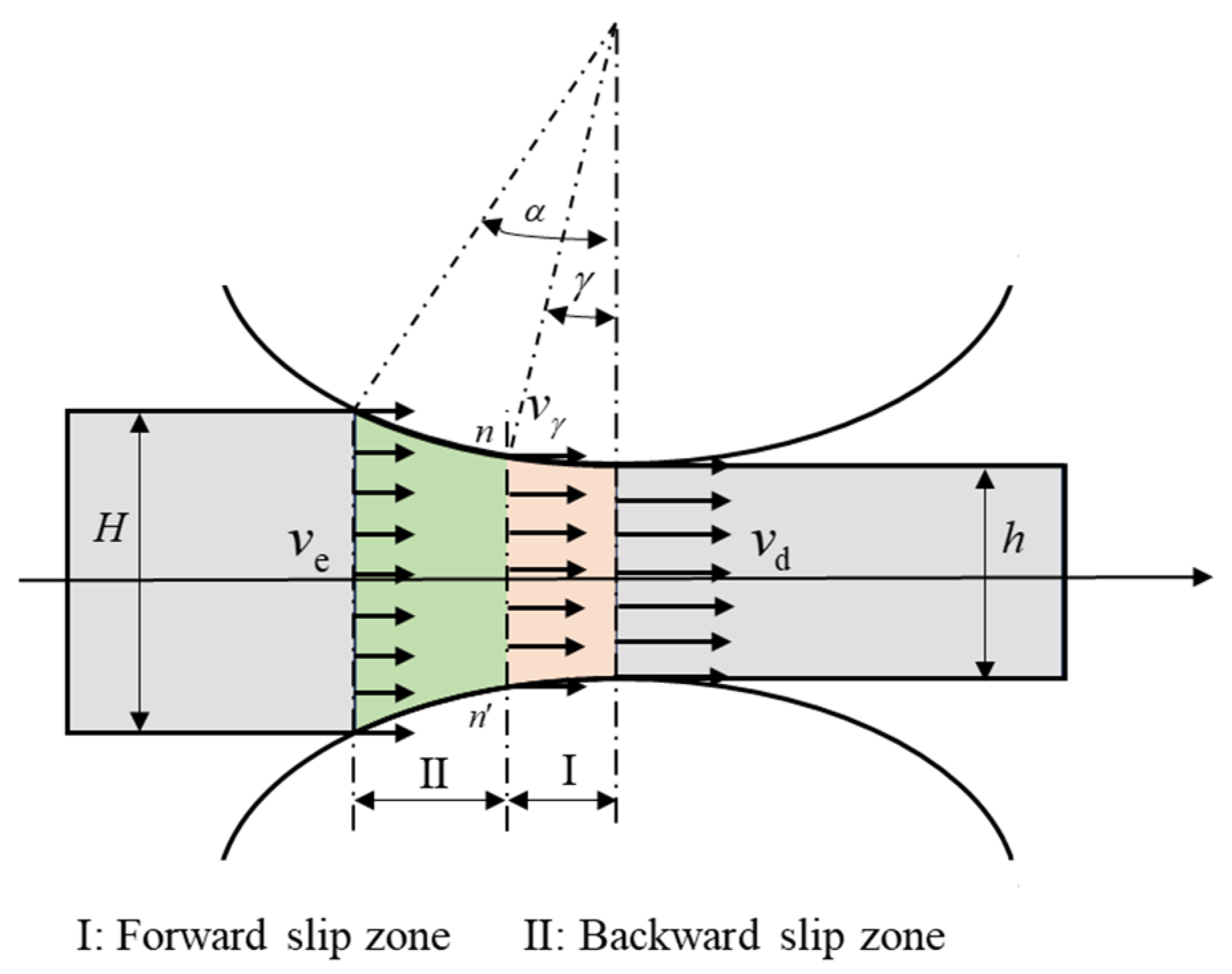
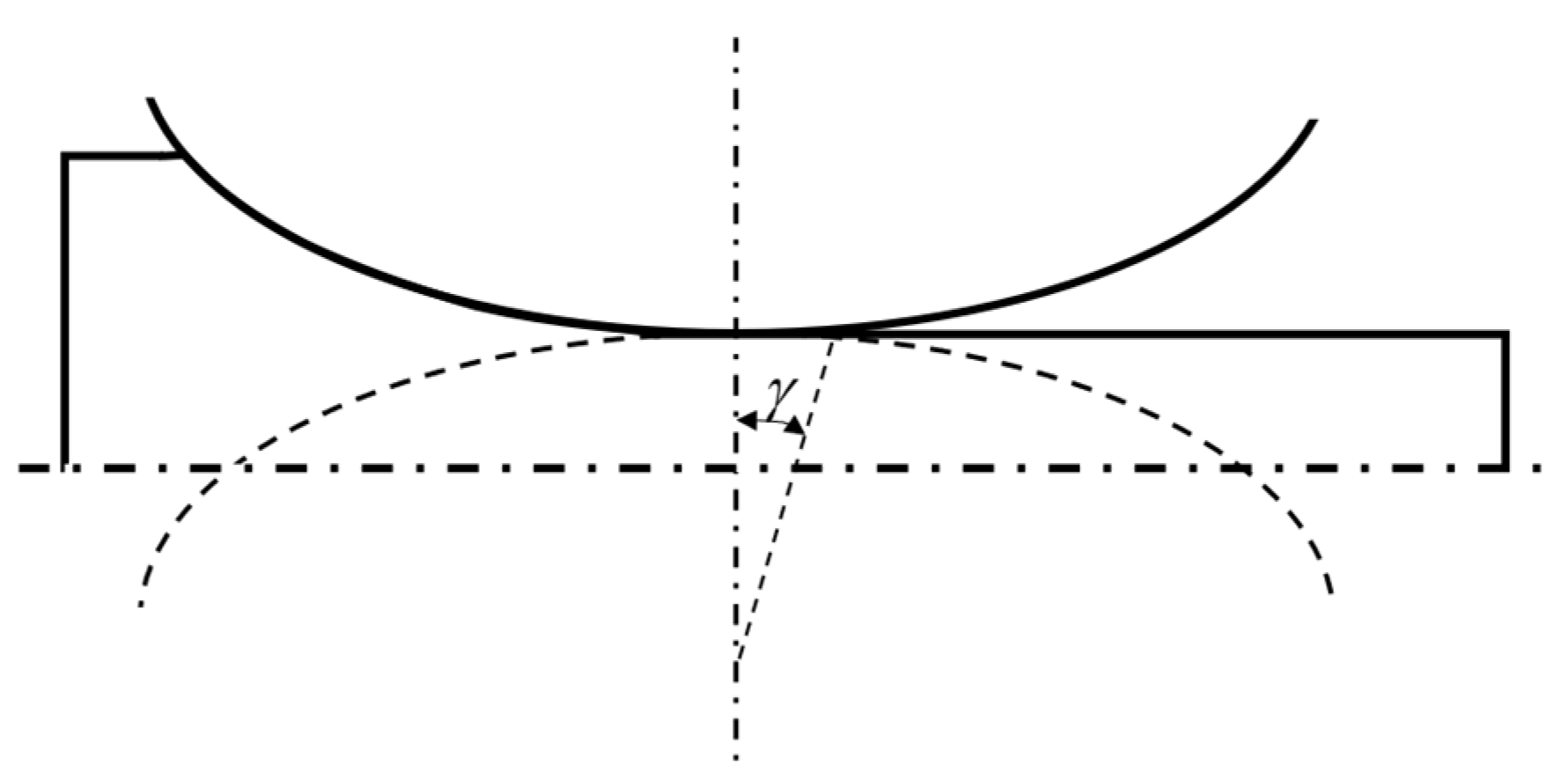
2.1. Modeling Based on Forward Slip Theory and Flatten Curve

As shown in Figure 1, in the deformation zone, the compressed metal flows along the rolling direction towards the inlet zone and exit zone, respectively. This causes the inlet speed of the strip v e to be less than the horizontal tangential speed of the roll, while the exit speed of the strip v d is greater than the rolling speed. Consequently, this leads to the phenomenon of backward slip and forward slip. Meanwhile, there is a plane where the speed of the strip is equal to the horizontal tangential speed of the roll, known as the neutral plane. The angle γ between the neutral plane and the center line of the roll is called the neutral angle.
According to rolling theory, the forward slip value is defined as
f = v d v r v r × 100 %
where v d is the exit speed of the strip, and v r is the rolling speed.
Ignoring the width spread, the relationship between the strip speed and thickness in the deformation zone is obtained by the material flow equation [22]:
v d h = v e H = v γ h γ
where H is the inlet thickness of the strip, h is the exit thickness of the strip, h y is the strip thickness at the neutral plane and v y is the strip speed at the neutral plane.
Substituting Equation (2) into Equation (1), the forward slip is written as
f = cos γ h γ h 1 × 100 %
According to Equation (3), the neutral angle and the strip thickness at the neutral plane are the key for calculating the forward slip. With the assumption that the roll is still an arc shape after being flattened, the strip thickness at the neutral plane can be expressed as
h γ = h + 2 R 1 cos γ
where R is the roll flattened radius, and it can be calculated by the Hitchcock formula.
R = 1 + C H P B ( H h ) R C H = 16 1 υ 2 π E
where B is the width of the strip, P is the rolling force, R is the roll radius, E is the Young’s modulus of the strip and υ is the Poisson’s ratio of the strip.
Substituting Equation (4) into Equation (3), the Fink forward slip model is derived as follows:
f = 1 cos γ 2 R cos γ h 1 × 100 %
When the neural angle is small, that is 1 cos γ γ 2 / 2 , and 2 R cos γ / h 1 0 , the Drezden forward slip model is presented in Equation (7):
f = R h γ 2 × 100 %
From Equation (7), the neutral angle is a necessary parameter for calculating the forward slip. It can be determined by the BLAND-FORD rolling force [23], as shown in
γ = h R tan 1 2 arctan ( r 1 r ) 1 4 μ h R ln ( h H 1 τ f K f 1 τ b K b )
where r is the reduction ratio, μ is the friction coefficient, τ f is the exit tension stress, τ b is the inlet tension stress, K f is the exit deformation resistance and K b is the inlet deformation resistance.
According to Equations (7) and (8), the BLAND-FORD forward slip model is defined as follows:
f = R h γ 2 × 100 % γ 0 f = 0 γ < 0
From Equations (6), (7) and (9), these classic forward slip models can only calculate positive forward slip and cannot predict negative forward slip.
As shown in Figure 2, when negative forward slip occurs, it is assumed that the strip continues to be rolled by the symmetrical rolls until the strip speed equals the horizontal tangential speed of the roll. The angle between this position and the center line of the roll is defined as the negative neutral angle, and the corresponding strip thickness can be expressed by Equation (10):
h γ = h 2 R 1 cos γ
Then, substituting Equation (10) into Equation (3), the analytical model of negative forward slip can be obtained:
f = cos γ 1 D ( 1 cos γ ) h 1 × 100 %
After further simplification, the formula for negative forward slip is
f = R h γ 2 × 100 %
Combining Equation (7) and Equation (12), the modified forward slip that can predict positive and negative forward slip is derived.
f = γ γ R h γ 2 × 100 %

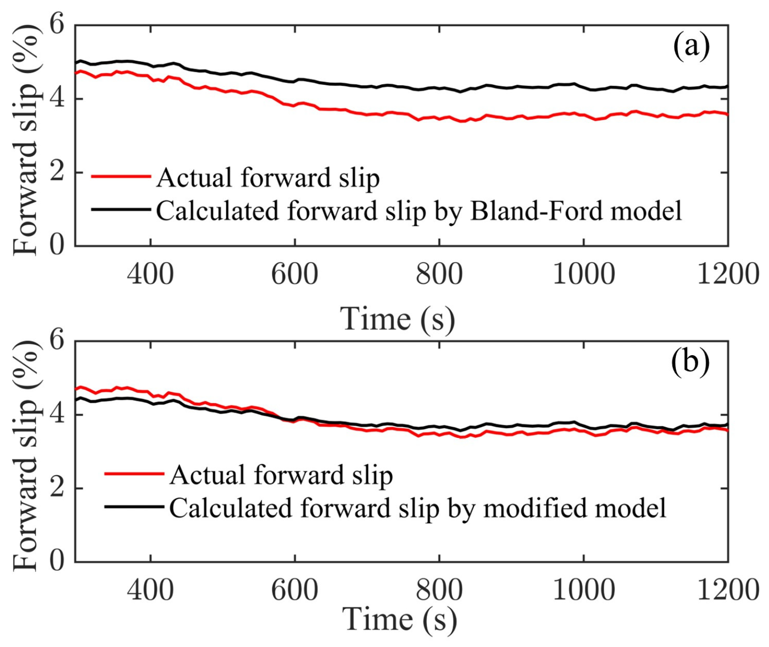
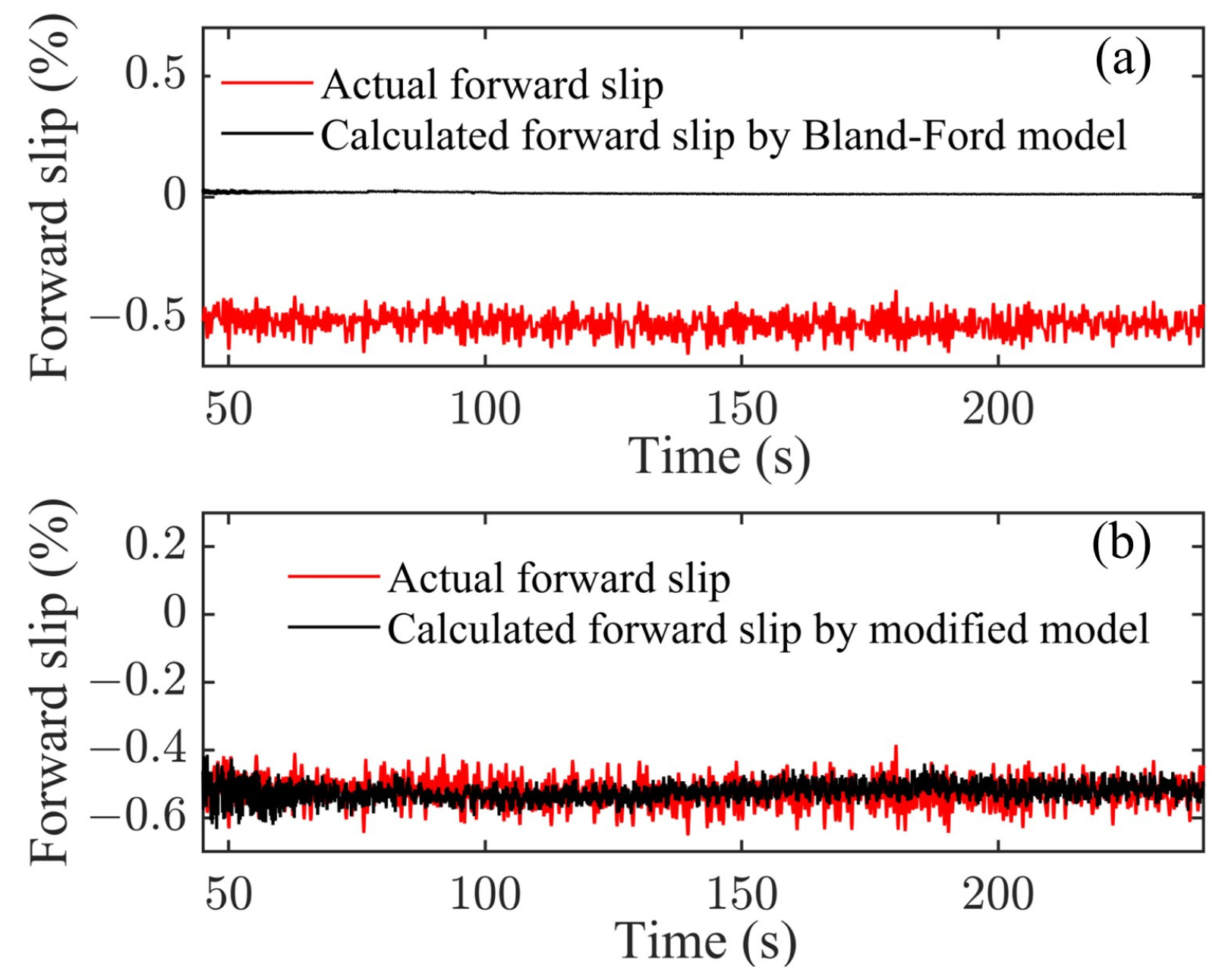
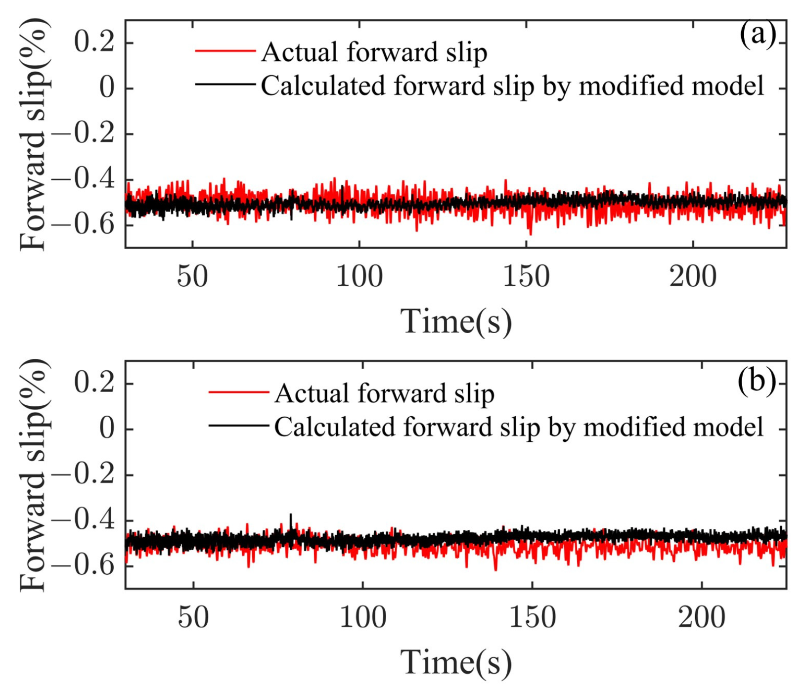
2.2. Application of Compensation Coefficient and Model Validation

Due to the assumptions and simplifications during the modeling process, the methods of model adaptation or introducing compensation coefficients are often used to improve the model’s calculation accuracy. In this section, a compensation coefficient is introduced into the neutral angle, as shown in Equation (14).
γ = h R tan 1 2 arctan ( r 1 r ) 1 4 α μ h R ln ( h H 1 τ f K f 1 τ b K b )
where α is the compensation coefficient.
Based on the analysis of the actual data, the compensation coefficient is defined by Equation (15):
α = a n τ f
where α n is the compensation factor, and its calculation will be provided later.
Next, the effectiveness of the modified model is verified via actual rolling data from two rolling production lines. The rolling process parameters are shown in Figure 3 and Figure 4, respectively.
Applying the classical BLAND-FORD forward slip model and the modified forward slip model with compensation coefficient, the comparison results between the calculated forward slip values and the actual forward slip values are presented in Figure 5 and Figure 6.
Figure 5 illustrates the comparison results of the forward slip during the stable stage on the first production line. Both models can calculate the positive forward slip, but it is obvious that the modified forward slip model has higher calculation accuracy.
Figure 6 presents the comparison results of the forward slip during the stable stage on the second production line. The classical BLAND-FORD forward slip model cannot calculate negative forward slip, whereas the modified forward slip model is able to calculate negative forward slip, and the calculated values are consistent with the actual values.
Analyzing 22 coils with the same strength grade after replacing the roll, the relationship between the compensation factor and the coil number is illustrated in Figure 7.
Figure 7 indicates an approximately linear relationship between the compensation factor and coil number. The formula can be derived by fitting on the discrete data:
a n = 0.0086 N r + 1.4864
where N r is the coil number after replacing the roll.
Combined with the obtained compensation coefficient, the modified forward slip model is applied to the 24th and 54th coils that are not involved in the fitting analysis. The comparison between the calculated forward slip values and the actual forward slip values are presented in Figure 8.
As shown in Figure 8, the modified forward slip is also applicable to other steel coils with the same strength grade after replacing the roll. Thus, for steel of other strength grades, the forward slip can generally be calculated in a similar way.
Based on the above analysis and application, it is evident that the modified model can predict the positive forward slip and negative forward slip, and the calculated values are highly consistent with the actual values. Therefore, compared to the classic forward slip model, this modified model effectively improves the calculation accuracy of the forward slip.

3. Influence of Parameters on Forward Slip

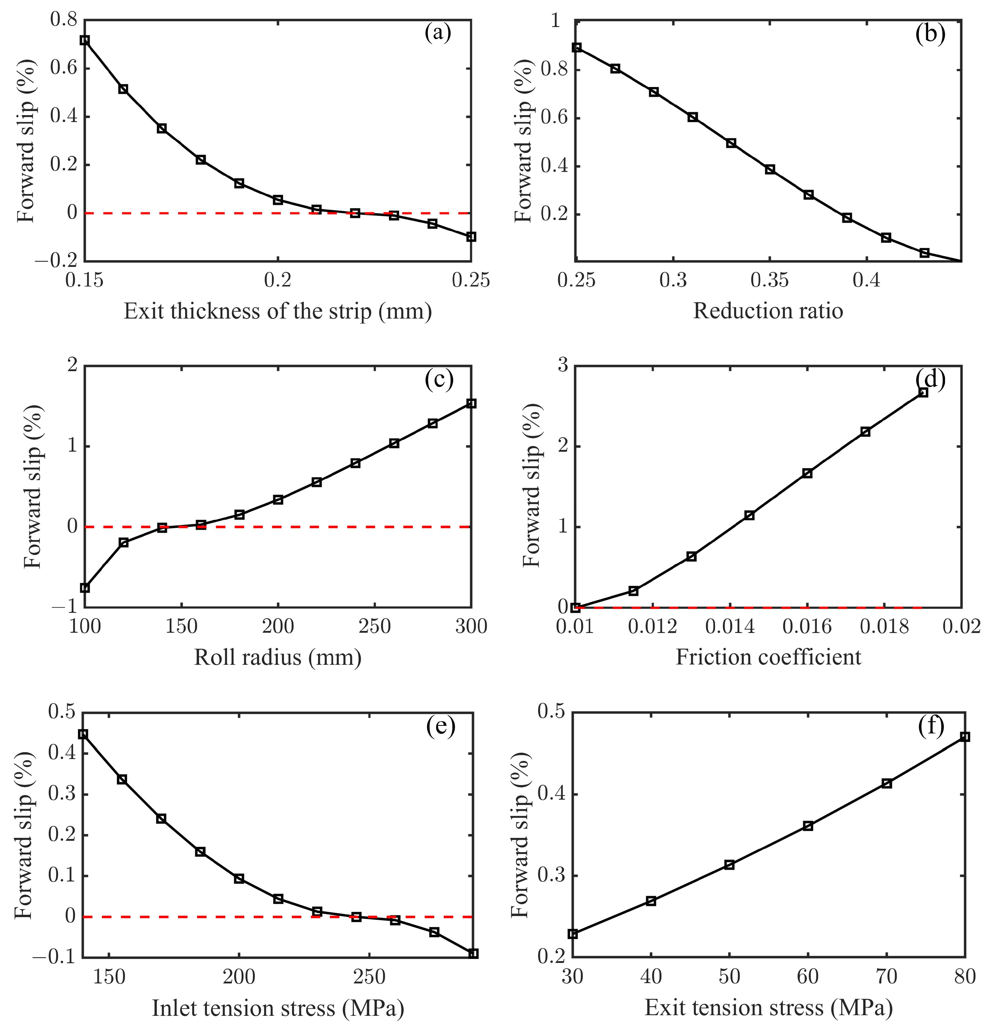
3.1. Variation of Forward Slip with Parameters

From the above modeling process, the forward slip can be expressed as a function of the relevant variables:
f = F R , h , r , μ , τ b , τ f
The parameter variations in Equation (17) directly affect the rolling force and indirectly change the roll flattened radius. Firstly, the influence of parameters on the roll flattened radius is determined by decoupling Equations (5) and (18). Then, the influence of parameters on the forward slip is analyzed.
P = ( Q p 2 3 1 υ 2 E k p h Δ h ) ( k p ξ ) B R Δ h ξ = 0.3 τ f + 0.7 τ b Q p = 1.08 + 1.79 r 1 r μ R h 1.02 r
where k p denotes the average deformation resistance, ξ is the equivalent tension influence coefficient, Q p is the external friction influence coefficient and Δ h is the reduction.
The typical specification parameters are presented in Table 1.
The formula for deformation resistance of this specification is as follows:
k = 554.96 ε + 0.5971 0.6445 ε = ln h 0 h x
where h 0 is the reference thickness of 2.01 mm, and h x is the strip thickness.
The influence of the parameters in Equation (17) on forward slip is illustrated in Figure 9.
As shown in Figure 9a, the forward slip decreases as the exit thickness of the strip increases, and it can become negative under certain conditions. When the reduction ratio remains constant and the exit thickness of the strip increases, the roll flattened radius and the neutral angle will decrease, ultimately leading to the occurrence of a negative forward slip.
As shown in Figure 9b, the forward slip decreases as the reduction ratio increases. When the exit thickness of the strip remains constant and the reduction ratio increases, both the roll flattened radius and the neutral angle decrease, which can result in negative forward slip under certain conditions.
As shown in Figure 9c, the forward slip increases as the roll radius increases. When the other parameters remain constant and the roll radius increases, the bite angle decreases, resulting in an increase in the residual friction force. This can promote the plastic flow of metal, ultimately leading to an increase in the forward slip.
As shown in Figure 9d, the forward slip increases with the increase in the friction coefficient. The residual friction force also increases with the friction coefficient, promoting the flow of metal and consequently resulting in an increase in the forward slip.
As shown in Figure 9e,f, the effects of inlet tension stress and exit tension stress on forward slip are opposite. The exit tension stress promotes the forward flow of metal, while inlet tension stress hinders the forward flow of metal and reduces the neutral angle. Therefore, their effects are opposite.

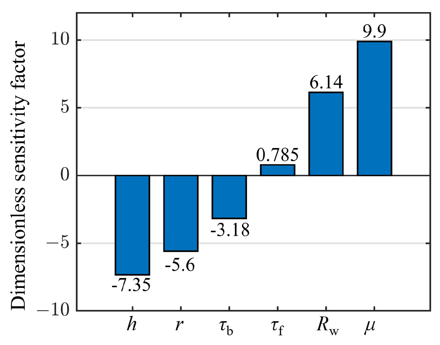
3.2. Comparison of Dimensionless Sensitivity Factor

According to the results in Section 3.1, the degree of variation in forward slip with respect to the parameters is different. In order to quantify the impact of these parameters, a dimensionless sensitivity factor is defined as follows:
s = f Δ f 0 / f 0 var Δ var 0 / var 0
where var 0 is the variable in Equation (17), f 0 is the corresponding forward slip value and var ( Δ ) and f ( var ) , respectively, represent a small increment at the given parameter and the corresponding forward slip value. The dimensionless sensitivity factors of the parameters (exit thickness, friction coefficient, roll radius, reduction ratio, exit tension stress and inlet tension stress) to forward slip are shown in Figure 10.
From Figure 10, it can be observed that forward slip is negatively correlated with strip exit thickness, reduction ratio and inlet tension stress while positively correlated with exit tension stress, friction coefficient and roll radius. Among them, the friction coefficient has the greatest positive influence on forward slip, while the exit thickness of the strip has the greatest negative influence. In actual production, due to the automatic gauge control (AGC) system, the exit thickness of the strip does not fluctuate much. Moreover, the change in the roll radius is relatively slow during the rolling process. Additionally, the reduction ration is typically set in advance. Therefore, adjusting the tension and friction coefficient are effective methods to change the forward slip.
From model validation and the analysis of influencing factors, it can be seen that the modified forward slip model can not only be used to regulate and optimize the rolling process parameters but also to be integrated into the control system in the further prospects to realize the automation and intelligent control of the cold rolling process.

4. Dynamic Tension Regulation Based on Stable Forward Slip

Forward slip, a crucial parameter in the rolling process, can reflect the stability of the rolling process to a certain extent. Figure 11 depicts the actual speed, vibration acceleration, forward slip and vibration energy of two steel coils on the fifth stand.
As shown in Figure 11a, the forward slip remains stable at around −1.0% during the stable rolling stage, and there is no vibration alarm. However, as depicted in Figure 11b, the vibration acceleration tends to diverge at 301 s and 418 s, with the vibration energy reaching and exceeding the alarm line, and there are also fluctuations of the forward slip. To avoid exacerbation of the vibrations, the rolling speed is reduced twice during the entire process. From the two steel coils, it can be seen that it is crucial to maintain a stable forward slip during the rolling process.
When the rolling speed remains unchanged, abnormal fluctuations of the forward slip can cause changes in the tension between the stands, which can affect the stability of rolling process. Figure 12 illustrates the speed, vibration acceleration, forward slip, exit tension stress, inlet tension stress and tension difference corresponding to the chatter interval of the fifth stand for a certain steel coil.
From Figure 12, it can be observed that, during the interval between 405 and 407 s, when the strip was being rolled at a speed of 12.92 m/s, the forward slip gradually increased, accompanied by dramatic fluctuations in both tension forces and the tension force difference. Concurrently, the vibration acceleration diverged sharply. During the speed reduction process from 407 to 411 s, the vibration acceleration reached its maximum approximately at 408 s. As the speed continued to decrease, the negative forward slip decreased, and the vibration acceleration converged. After 411 s, the vibration acceleration converged. Correspondingly, the forward slip, inlet tension force, exit tension force and tension force difference all reached a new equilibrium state. Moreover, while the range of the exit tension force remained basically unchanged before and after the speed reduction, both the forward slip and inlet tension force increased slightly after the speed reduction.
Therefore, in this section, forward slip is considered an observation indicator for rolling stability, and it is maintained within a range to achieve stable rolling. From the analysis above, the friction coefficient and tension stresses are the main factors affecting forward slip. Since the range of exit force remains basically unchanged, the relationship between forward slip and the inlet tension force, as well as the friction coefficient, is illustrated in Figure 13.
As can be seen from Figure 13b, when the friction coefficient is 0.0167 and inlet tension stress is 65 kN, the forward slip is −0.0075, which corresponds to a stable rolling state before the speed reduction in Figure 12. When the speed is reduced to another stable stage with the friction coefficient of 0.0182 and the inlet tension stress of 72 kN, the forward slip value is −0.0055, which is consistent with the new stable state after the speed reduction. Analyzing the chatter interval of 405~407 s, the actual forward slip value and the calculated forward slip value are shown in Figure 14.
According to Figure 12, during stable rolling interval at the speed of 12.92 m/s, the forward slip is approximately between −0.8% and −0.7%, with the inlet tension force between 64 kN and 70 kN. During the chatter interval, the forward slip gradually increases to approximately 0.05%, with the inlet tension force fluctuating between 50 kN and 90 kN. Therefore, to stabilize the rolling process, the forward slip is maintained at −0.75% by dynamically regulating the inlet tension force. The comparison results before and after the regulation are shown in Figure 15. The inlet tension force is adjusted to approximately 64.96 kN, which is within the stable range (64 kN~70 kN), and the fluctuation of tension force difference is smaller than that of stable rolling before regulation. Consequently, the rolling mill can be avoided.

5. Conclusions

Considering the influence of forward slip on the rolling stability, this paper focuses on the problem that the classical forward slip models cannot predict negative forward slip in actual production, aiming to establish a novel modified forward slip model and stabilize the rolling process. The research content includes the following aspects:
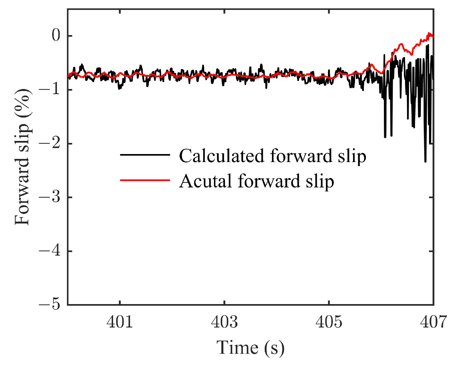
  • By characterizing the strip thickness corresponding to negative forward slip and combining it with the forward slip theory, the modified forward slip model is established. Moreover, after applying the compensation coefficient related to tension and coil number in the proposed model, the results shows that the modified model can calculate both positive and negative forward slips in different steel coils. The calculated results are in alignment with the actual outcomes, thereby verifying the effectiveness of the modified model. It should be noted that the modified forward slip model is universal, but the compensation coefficient needs to be obtained according to the specific specifications and materials.
  • The influence of the parameters on forward slip is analyzed, including strip exit thickness, inlet tension stress, exit tension stress, friction coefficient and roll radius, and the dimensionless sensitivity factor is defined to quantify the degree of influence. Notably, the friction coefficient has the greatest positive influence on forward slip, whereas the exit thickness of the strip demonstrates the greatest negative influence.
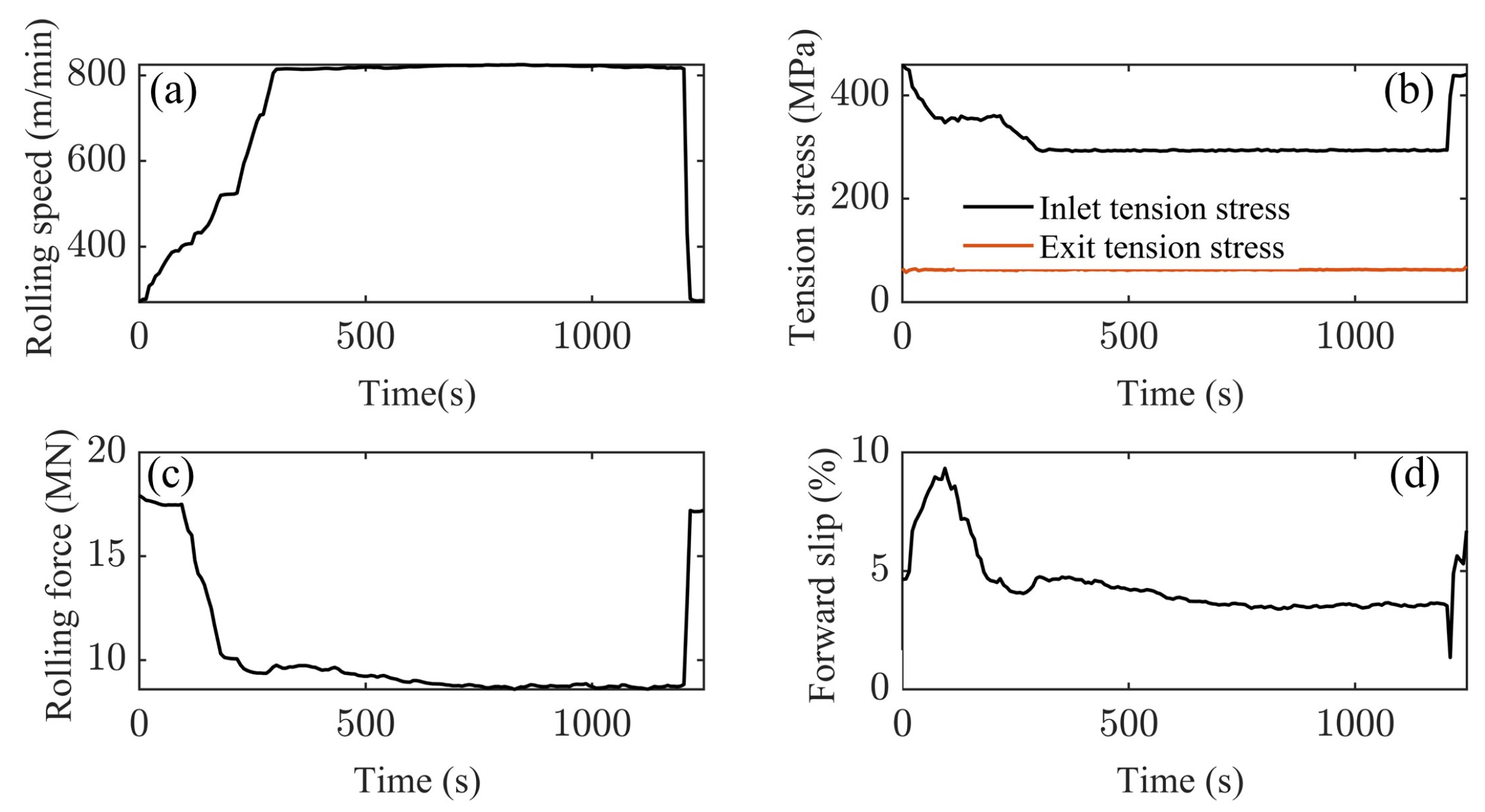
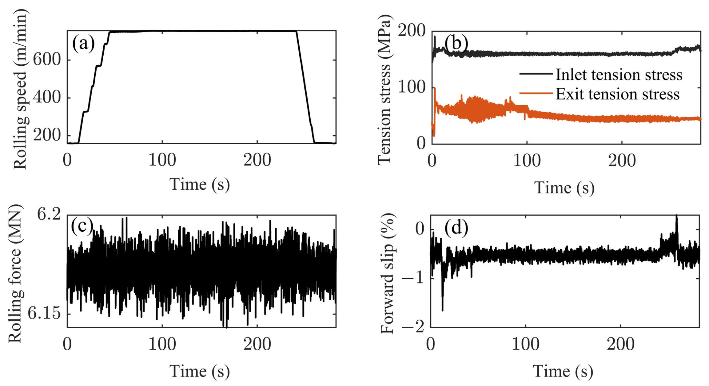
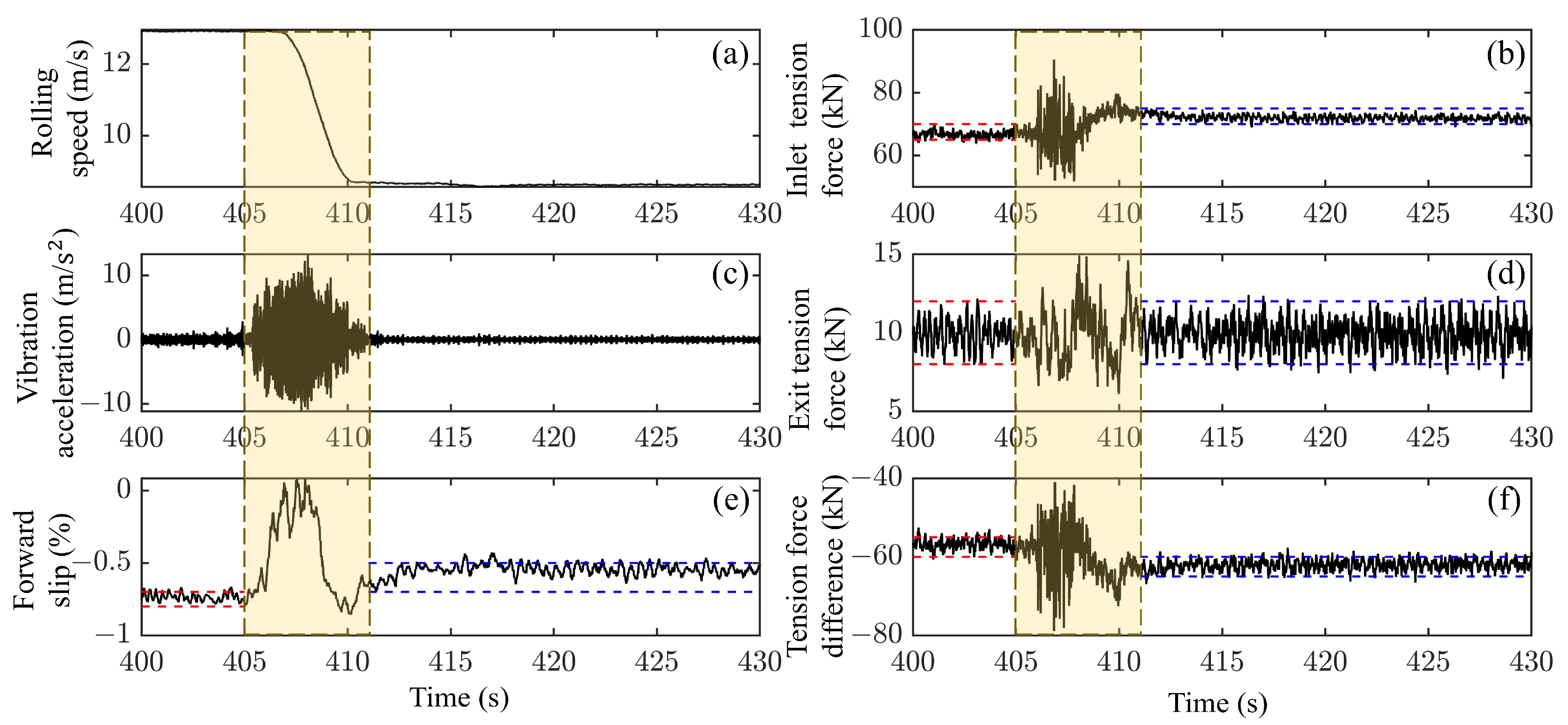
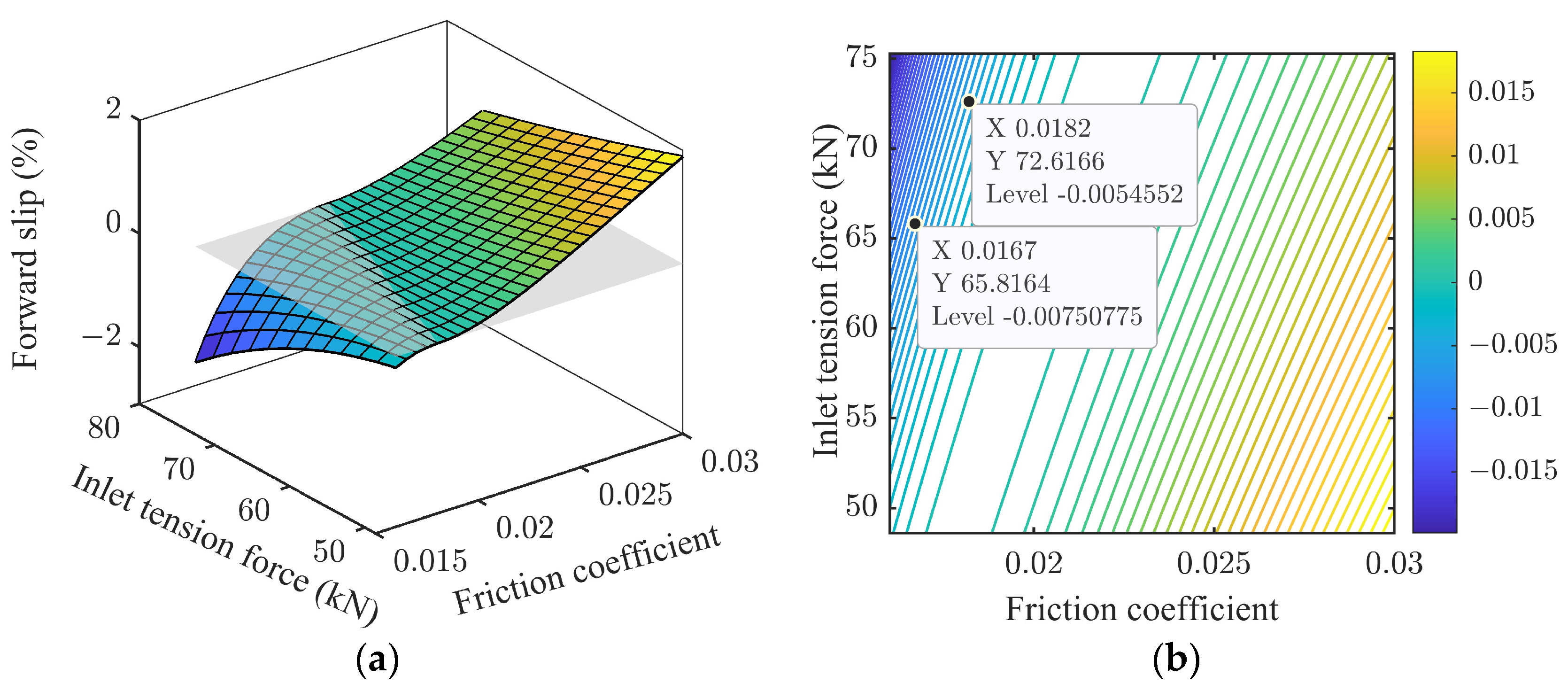
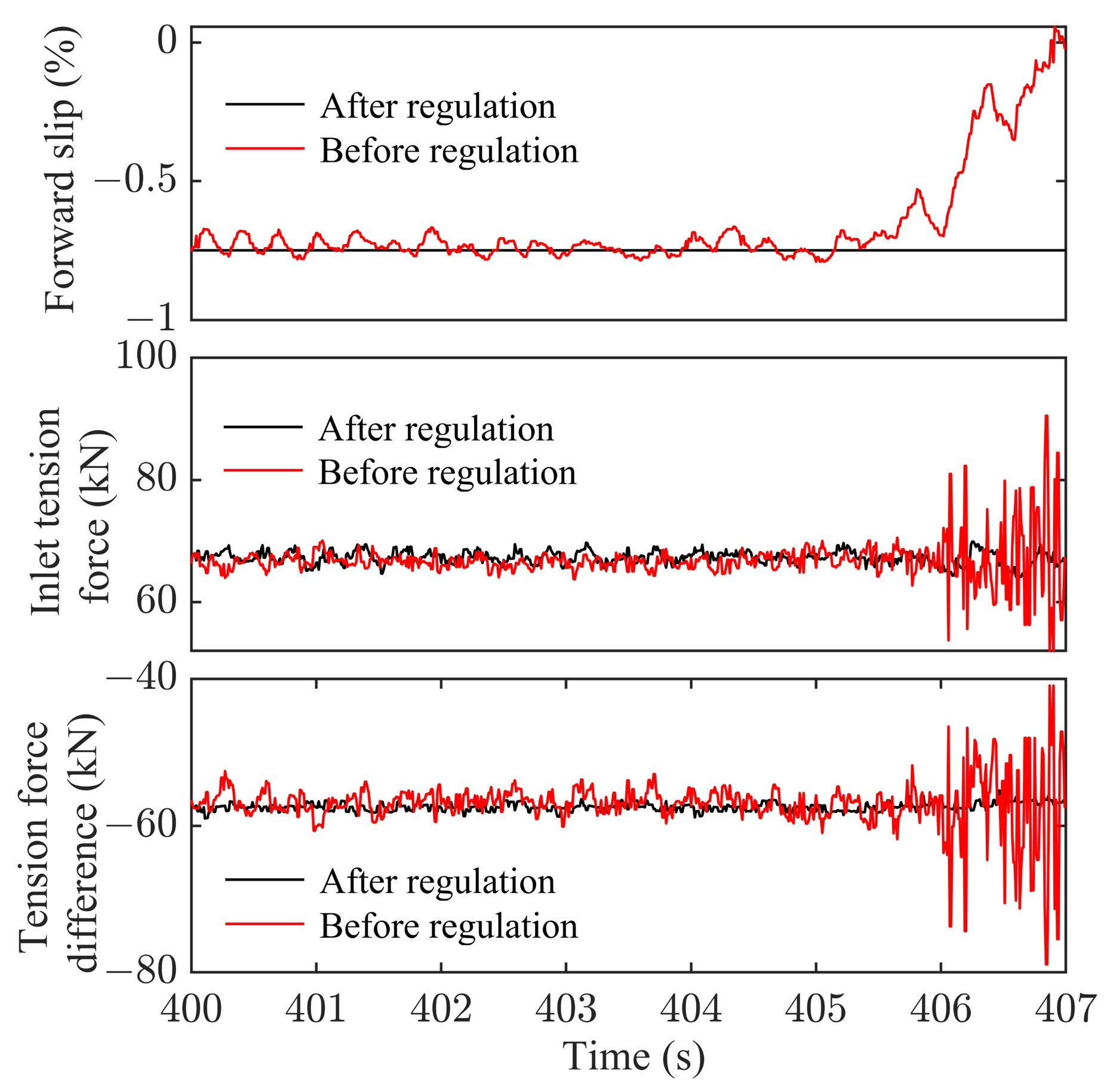
  • Recognizing forward slip as an observable indicator of rolling process stability, the tension regulation strategy is proposed to maintain forward slip within a stable range. Analyzing the parameters of the chatter interval, forward slip is stabilized at approximately −0.75% by adjusting the inlet tension force, effectively avoiding the exacerbation of parameter fluctuations and rolling mill chatter.

Author Contributions

Conceptualization, X.W. and Y.X.; methodology, Y.X.; software, Y.X.; validation, Y.X., Z.G. and X.W.; formal analysis, Y.X.; investigation, Y.X.; resources, Z.G. and Y.Z.; data curation, Y.X.; writing—original draft preparation, Y.X.; writing—review and editing, Z.G.; visualization, X.W.; supervision, Z.G. and Y.Z.; project administration, Z.G. and Y.Z.; funding acquisition, Z.G. and Y.Z. All authors have read and agreed to the published version of the manuscript.

Funding

This research was funded by the National Natural Science Foundation, China (No. 51775038).

Data Availability Statement

The data presented in this study are available on request from the corresponding author. The data are not publicly available due to privacy or ethical restrictions.

Conflicts of Interest

The authors declare no conflicts of interest.

References

  1. Wang, W.L. Influence factors of forward slip value and its application in cold rolling production. Shanxi Metall. 2023, 46, 156–158. [Google Scholar] [CrossRef]
  2. Moon, H.Y.; Jo, S.I.; Tyne, J.C. Control scheme using forward slip for a multi-stand hot strip rolling mill. KSME Int. J. 2004, 18, 972–978. [Google Scholar] [CrossRef]
  3. Bayoumi, L.S. A kinematic analytical approach to predict roll force, rolling torque and forward slip in thin hot strip continuous rolling. Ironmak. Steelmak. 2007, 34, 444–448. [Google Scholar] [CrossRef]
  4. Qu, F.J.; Xu, J.Z.; Jiang, Z.Y. Finite element analysis of forward slip in micro flexible rolling of thin aluminium strips. Metals 2019, 9, 1062. [Google Scholar] [CrossRef]
  5. Poursina, M.; Rahmatipour, M.; Mirmohammadi, H. A new method for prediction of forward slip in the tandem cold rolling mill. Int. J. Adv. Manuf. Technol. 2015, 78, 1827–1835. [Google Scholar] [CrossRef]
  6. Fujii, Y.; Maeda, Y.; Utsunomiya, H. Development of On-line model of forward slip on tandem cold strip mill. ISIJ Int. 2021, 107, 732–740. [Google Scholar] [CrossRef]
  7. Bu, H.N.; Yan, Z.W.; Zhang, D.H. A novel approach to improve the computing accuracy of rolling force and forward slip. Ironmak. Steelmak. 2019, 46, 269–276. [Google Scholar] [CrossRef]
  8. Zhao, H.P.; Pan, G. Application of Bland-Ford forward slip model in Baosteel cold rolling’s model system. Baosteel Technol. 2009, 4, 63–66+70. [Google Scholar]
  9. Cao, J.; Fan, Z.J.; Liu, Y.J.; Chen, W.; Liu, L. Study of forward slip model application and adjustment for tandem cold mill. In Proceedings of the 11th CSM Steel Congress, Beijing, China, 21 December 2017. [Google Scholar]
  10. Wang, Q.Y.; Zhu, Y.; Zhao, Y. Friction and forward slip in high-speed cold rolling process of aluminum alloys. Appl. Mech. Mater. 2012, 229–231, 361–364. [Google Scholar] [CrossRef]
  11. Lenard, J.G.; Zhang, S. A study of friction during the lubricated cold rolling of an aluminum alloy. J. Mater. Proc. Technol. 1997, 72, 293–301. [Google Scholar] [CrossRef]
  12. McConnell, C.; Lenard, J.G. Friction in cold rolling of a low carbon steel with lubricants. J. Mater. Process Technol. 2000, 99, 86–93. [Google Scholar] [CrossRef]
  13. Shirizly, A.; Lenard, J.G. Emulsions versus neat oils in the cold rolling of carbon steel strips. J. Tribol. 2000, 122, 550–556. [Google Scholar] [CrossRef]
  14. Lu, C.; Tieu, A.K. Measurement of the forward slip in cold strip rolling using a high speed digital camera. J. Mech. Sci. Technol. 2007, 21, 1528–1533. [Google Scholar] [CrossRef]
  15. Kiani, R.; Gali, O.A.; Hunter, J.A.; Riahi, A.R. An Evaluation of the influence of forward slip on the corrosion behavior of aluminum-manganese alloys. J. Mater. Eng. Perform. 2021, 30, 5811–5824. [Google Scholar] [CrossRef]
  16. Bai, Z.H.; Lian, J.C.; Wang, J.F. Screw-down schedule optimization for preventing slippage on cold tandem mill. Iron Steel 2003, 10, 35–38. [Google Scholar] [CrossRef]
  17. Wang, Y.; Li, C.S.; Jin, X.; Xiang, Y.G.; Li, X.G. Multi-objective optimization of rolling schedule for tandem cold strip rolling based on NSGA-II. J. Manuf. Process 2020, 60, 257–267. [Google Scholar] [CrossRef]
  18. Wang, Y.; Wang, J.; Yin, C.; Zhao, Q. Multi-objective optimization of rolling schedule for five-stand tandem cold mill. IEEE Access 2020, 8, 80417–80426. [Google Scholar] [CrossRef]
  19. Kozhevnikov, A.V.; Kozhevnikova, I.A.; Bolobanova, N.L. Development of the model of cold rolling process in dynamic conditions. J. Chem. Technol. Metall. 2018, 53, 366–372. [Google Scholar]
  20. Cao, L.; Li, X.; Zhang, D. Research into the effect of flatness control actuators on vibration stability in cold rolling using the finite element method. Int. J. Adv. Manuf. Technol. 2023, 125, 245–266. [Google Scholar] [CrossRef]
  21. Wang, Y. Deformation Resistance and Forward Slip Model of High Strength Steel During Cold Rolling. Master’s Thesis, Northeastern University, Shenyang, China, 2017. [Google Scholar] [CrossRef]
  22. Reddy, V.N.; Suryanarayana, G. A set-up model for tandem cold rolling mills. J. Mater. Proc. Technol. 2001, 116, 269–272. [Google Scholar] [CrossRef]
  23. Bland, D.R.; Ford, H. The calculation of roll force and torque in cold strip rolling with tensions. Proc. I. Mech. Eng. 1948, 159, 144–153. [Google Scholar] [CrossRef]
Figure 1. Schematic diagram of the metal flow velocity in the deformation zone.
Lubricants 12 00404 g001
Figure 2. Schematic diagram of negative forward slip.
Lubricants 12 00404 g002
Figure 3. Rolling process parameters of the first production line: (a) rolling speed; (b) tension stress; (c) rolling force; (d) forward slip.
Lubricants 12 00404 g003
Figure 4. Rolling process parameters of the second production line: (a) rolling speed; (b) tension stress; (c) rolling force; (d) forward slip.
Lubricants 12 00404 g004
Figure 5. Comparison results of forward slip on the first production line. (a) Results of the BLAND-FORD forward slip model. (b) Results of the modified forward slip.
Lubricants 12 00404 g005
Figure 6. Comparison results of forward slip on the second production line. (a) Results of the BLAND-FORD forward slip model. (b) Results of the modified forward slip.
Lubricants 12 00404 g006
Figure 7. Relationship between compensation factor and coil number.
Lubricants 12 00404 g007
Figure 8. Application of the modified forward slip model. (a) Comparison of the forward slip values for the 24th coil. (b) Comparison of the forward slip values for the 54th coil.
Lubricants 12 00404 g008
Figure 9. Influence of the parameters on forward slip. (a) Exit thickness of the strip. (b) Reduction ration. (c) Roll radius. (d) Friction coefficient. (e) Inlet tension stress. (f) Exit tension stress.
Lubricants 12 00404 g009
Figure 10. Dimensionless sensitivity factors.
Lubricants 12 00404 g010
Figure 11. Phenomenon of negative forward slip in actual production. (a) The first steel coil. (b) The second steel coil.
Lubricants 12 00404 g011
Figure 12. Response of the vibration and rolling process parameters. (a) Rolling speed. (b) Inlet tension force. (c) Vibration acceleration. (d) Exit tension force. (e) Forward slip. (f) Tension force difference.
Lubricants 12 00404 g012
Figure 13. Influence of the friction coefficient and inlet tension force on forward slip and the forward slip contour map. (a) Influence of friction coefficient and inlet tension force on forward slip. (b) Forward slip contour map.
Lubricants 12 00404 g013
Figure 14. Comparison of forward slip before the speed reduction.
Lubricants 12 00404 g014
Figure 15. Comparison before and after tension control.
Lubricants 12 00404 g015
Table 1. Parameters affecting the forward slip.
ParameterValue
Strip width B 936 mm
Roll radius R 200 mm
Strip Inlet thickness H 0.267 mm
Strip Exit thickness h 0.171 mm
Friction coefficient μ 0.02
Reduction ration r 0.3596
Inlet tension stress τ b 155 MPa
Exit tension stress τ f 55 MPa
Disclaimer/Publisher’s Note: The statements, opinions and data contained in all publications are solely those of the individual author(s) and contributor(s) and not of MDPI and/or the editor(s). MDPI and/or the editor(s) disclaim responsibility for any injury to people or property resulting from any ideas, methods, instructions or products referred to in the content.

