Article

Thermal–Elastohydrodynamic Lubrication Characteristics of the Flow Distribution Pair of Balanced Double-Row Axial Piston Pumps

School of Mechatronics Engineering, Anhui University of Science and Technology, Huainan 232000, China
*
Author to whom correspondence should be addressed.
Lubricants 2024, 12(10), 342; https://doi.org/10.3390/lubricants12100342
Submission received: 4 September 2024 / Revised: 27 September 2024 / Accepted: 29 September 2024 / Published: 2 October 2024

Abstract

:
A theoretical model for the calculation of thermal elastohydrodynamic lubrication performance of the flow distribution pair of piston pumps is established, which is composed of the oil film pressure governing equation and energy equation, and solved by means of numerical solution and simulation. We carry out quantitative analysis of the influence of various parameters on the thermal elastohydrodynamic lubrication characteristics of the flow distribution pair. The results indicate that both the oil film thickness and the cylinder tilt angle of the flow distribution pair vary in a periodic manner. The increase in the rotational speed of the cylinder block will increase the film thickness of the oil film and reduce the fluctuation, and the inclination angle of the cylinder block and its fluctuation amplitude will decrease. An increase in working pressure will lead to a decrease in the average oil film thickness, an increase in fluctuations, and an elevation in both the tilt angle of the cylinder block and its fluctuation amplitude. The increase in the rotational speed of the cylinder block and the increase in the working pressure will lead to the increase in the viscous friction dissipation of the flow distribution pair, the increase in the oil film temperature and the increase in the leakage. The reduction in the sealing belt will lead to the reduction in oil film friction torque and leakage.

1. Introduction

The flow distribution pair is one of the three major friction pairs in the axial piston pump [1,2,3,4]. It has the characteristics of complex structure, fast rotation speed, and high pressure. When working, the oil film of the flow distribution pair will produce viscous dissipation and heat under shear action, which will raise the temperature of the oil film and decrease the viscosity, resulting in thermoelastic deformation of the cylinder block and the distribution plate [5,6,7,8], thereby affecting the working performance and service life of the axial piston pump. Monika et al. [9,10] investigated the energy loss associated with the piston pump distribution pair, and designed the surface of the flow distribution pair macroscopically and microscopically to minimize the friction of the flow distribution pair and enhance its leakage. Kim et al. [11] conducted an experimental study on the lubrication characteristics of the piston pump under different distribution structures. The results show that under the same working conditions, compared with the plane distribution pair, the lubrication characteristics of the spherical distribution pair are the best. Han et al. [12] introduced a local lubrication model that incorporates time-varying curvature of the contact surface roughness to predict changes in the oil film height of the flow distribution pair. Wang et al. [13] investigated the wedge oil film thickness, pressure, and temperature distribution of the flow distribution pair of axial piston pumps using the finite difference and relaxation iteration method, and analyzed the lubrication characteristics under various working conditions, including both tilted and non-tilted cylinder scenarios. Additionally, to examine the impact of the surface morphology of the distribution plate on the lubrication characteristics of the flow distribution pair. Zhang Jiao et al. [14] used the fractal theory to simulate the surface morphology of the distribution plate, established the lubrication model of the flow distribution pair of the axial piston pump, and used the finite difference method to solve the model. The effects of fractal parameters on the surface profile were explored, and a further analysis was conducted on how both the fractal parameters and the working parameters of the flow distribution pair impact the oil film bearing capacity, friction force, friction torque, and friction coefficient. Hou Liang et al. [15] considered the oil film pressure distribution and torque effect of the auxiliary support belt with surface texture, established the oil film dynamics model of the flow distribution pair, and analyzed the variation of the flow leakage and friction loss of the flow distribution pair under different working pressures, working speeds, and swash plate angles. Hu Jibin et al. [16] developed a lubrication mathematical model for the flow distribution pair under elastic deformation conditions by applying the theory of elastic hydrodynamic lubrication. They utilized the finite difference method to solve the model’s governing equations and analyzed the effects of elastic deformation on the lubrication characteristics of the flow distribution pair. Lu et al. [17] studied the coupling effect between lubrication behavior and gear load distribution. An analytical load distribution model of spur gear pair in transient non-Newtonian thermal EHL contact was proposed. Xu et al. [18] proposed the calculation method of time-varying meshing characteristic parameters. By integrating these characteristic parameters, the thermal EHL numerical model of the REHW actuator was established based on EHL theory.
In comparison to a standard balanced axial piston pump, the balanced double-row axial piston pump [19,20,21] offers advantages such as enhanced balance and improved me-chanical properties. The distribution pair has bilateral high pressure, which makes its lubrication characteristics significantly different from those of ordinary piston pumps. It is essential to reassess the effects of various factors on its operational performance, including the thermoelastic deformation of the cylinder block and distribution plate, oil film viscosity, dynamic pressure, temperature, and others [22,23,24]. To address this, this paper develops a numerical model for the thermal elastohydrodynamic lubrication performance of the flow distribution pair of the balanced double-row axial piston pumps. The thermal elastohydrodynamic lubrication problem of the flow distribution pair is solved by means of numerical solution and simulation. Additionally, a quantitative analysis is conducted on how various parameters affect the oil film lubrication characteristics of the flow distribution pair. The lubrication theory of the port plate pair of the balanced double-row axial piston pump is further improved, and the theoretical research of the port plate of the balanced double-row axial piston pump is filled. This work provides a certain reference value for subsequent engineers and practitioners to improve the service life and working performance of the balanced double-row axial piston pump.

2. Thermal EHL Model of Flow Distribution Pair

2.1. Oil Film Pressure Governing Equations

We consider the geometric structure and oil film distribution of the flow distribution pair. It is described by the Reynolds equation in cylindrical coordinates, as shown in Equation (1):
1 r θ ρ h 3 r μ P θ + 1 r r ρ r h 3 μ P r = 6 ω ρ h θ + 12 h t
In order to investigate the effect of oil viscosity on its dynamic lubrication characteristics, the Reolands equation was employed to illustrate the relationships between viscosity and pressure, as well as viscosity and temperature, of hydraulic oil, as shown below [25]:
μ = μ 0 exp ln μ 0 + 9.67 1 + 5.1 P 10 18 z T 138 T 0 138 s 1
z = a p 5.1 × 10 9 ln μ 0 + 9.67 s = a T T 0 138 ln μ 0 + 9.67
where μ0 is the viscosity of hydraulic oil at standard atmospheric pressure; T is the hydraulic oil temperature; T0 is the reference temperature of hydraulic oil; aT is the viscosity–temperature coefficient of hydraulic oil; ap is the viscosity–pressure coefficient of hydraulic oil.

2.2. Energy Equation

Considering the influence of temperature variations on the flow distribution pair, the cylinder block, distribution plate, and lubricant oil film will eventually reach a stable state of heat production and heat dissipation, and the equation of oil film energy is expressed as follows [5,26]:
ρ c p v r T r + v θ r T θ + v z T z = λ f 1 r r r T r + 1 r 2 2 T θ 2 + 2 T z 2 + μ Φ d
where cp is the specific heat capacity of hydraulic oil; vz is the velocity component of the oil film in the z direction; Φd is the dissipation function; ρ is the density of hydraulic oil; λf is the thermal conductivity of hydraulic oil.
Temperature has an important effect on the density of lubricating oil. The density–temperature equation of hydraulic oil is expressed as follows:
ρ = ρ 0 1 6.5 × 10 4 T 293
where ρ0 is the reference density of the oil fluid (kg/m3).
Formula (4) has a typical form of the scalar transport equation, where the temperature in the lubricant is transferred by convection and diffusion. In addition, there is a source term in Equation (4) represented by the dissipation function Φd; the dissipation function represents the heat generated by the shear motion in the unit in the cylindrical coordinate system, and the dissipation function can be expressed as follows:
Φ d = 2 v r r 2 + 1 r v θ θ + v r r 2 + v z z 2 + r r v θ r + 1 r v r θ 2      + 1 r v z θ + v θ z 2 + v r z + v z r 2 2 3 1 r r r v r + 1 r v θ θ + v z z 2
According to the literature, the velocity distribution and oil film pressure distribution of the flow field of flow distribution pair in the r and θ directions are shown in Equation (7):
v θ = 1 2 μ P r θ ( z 2 z h ) + r ω z h v r = 1 2 μ P r ( z 2 z h )
Since the thickness of the oil film in the flow distribution pair is very small, on the order of microns, its velocity vector in the direction z of the oil film thickness can be ignored, that is, Vz = 0. Then, Formula (6) can be simplified as follows:
Φ d = 2 v r r 2 + 1 r v θ θ + v r r 2 + r r v θ r + 1 r v r θ 2             + v θ z 2 + v r z 2 2 3 1 r r r v r + 1 r v θ θ 2
Considering that the gradient of the oil film velocity vector vr and vθ in the z direction of the oil film thickness is much larger than that in the r and θ directions, then
v r r = v θ θ = v r θ = v θ r 0
According to the above formula, the dissipation function Φd can be simplified as follows:
Φ d = v θ z 2 + v r z 2 + 4 3 v r r 2 + v θ r 2
Since the velocity vector vz in the direction of the film thickness of the flow distribution pair is ignored relative to the circumferential vector vθ and radial directions vector vr, the convection term in the direction of the film thickness and the thermal conduction term in the circumferential and radial directions can be disregarded [27], so the energy Equation (4) can be simplified as follows:
ρ c p v r T r + v θ r T θ = λ f 2 T z 2 + μ Φ d

2.3. Thermal Conduction Equation

Due to the influence of leakage, friction power consumption, and other factors, the oil film of the flow distribution pair continuously generates heat, part of the heat is absorbed by the oil film of the flow distribution pair, and the rest is heat exchanged through the oil film and cylinder block, as a distribution plate heat exchange. The heat transfer characteristics of the flow distribution pair will affect its lubrication characteristics, and the lubrication characteristics can determine its thermal boundary conditions and heat generation mechanism. In this interaction, the dynamic performance and stability of the piston pump will be affected by both. Therefore, in addition to solving the energy equation of the flow distribution pair, it is also necessary to consider the heat conduction between the oil film and the cylinder block and the distribution plate. Under the consideration of the influence of the heat transfer characteristics of the oil film and the liquid–solid interface of the cylinder block and distribution plate, the time-dependent change term of the surface temperature of the flow distribution pair is introduced, the heat conduction equation for the cylinder block in cylindrical coordinates is expressed as follows:
2 T c r 2 + 1 r T c r + 1 r 2 2 T c θ 2 + 2 T c z 2 = 0
where Tc is the cylinder body with surface temperature.
Similarly, the heat conduction equation for the distribution plate is expressed as follows:
2 T p r 2 + 1 r T p r + 1 r 2 2 T p θ 2 + 2 T p z 2 = 0
where Tp is the distribution plate matching the surface temperature.

2.4. Model Discretization and Numerical Solution

To calculate the thermal elastohydrodynamic lubrication performance of the flow distribution pair of the balanced double-row axial piston pump, it is necessary to solve the lubrication models such as the oil film pressure governing equations, the energy equation, and the solid-state heat conduction. Among them, the oil film pressure control equation, the energy equation, and the solid heat conduction equation are all composed of quadratic partial differential equations. It is generally difficult to use the analytical method to solve them. Especially for the complex shape of the axial piston pump distribution pair, the numerical method is selected to solve it, so the finite difference method can be employed for an accurate solution.
The flow distribution pair of the balanced double-row axial piston pump can be divided into six pressure solving regions: inner row inner/outer sealing belt, outer row inner/outer sealing belt, and flow distribution region. Before the numerical discretization of the oil film pressure governing equations, the oil film solution domain is first discretized into a series of nodes, and then the oil film solution domain is divided into equal spacing grids: the radial division is equal to m − 1, and the radial spacing of the unit grid ∆r = (r8 − r1)/(m − 1). The axial spacing of the unit grid is ∆θ = 2π/(n − 1). Therefore, there are m × n grid nodes in the oil film solution domain, and the positions of the nodes are represented by (i, j), then the coordinates of any node of the oil film are (rj = r1 + (j − 1)∆r, θi = (i − 1)∆θ), as shown in Figure 1.
Under polar coordinates, the finite difference method adopts the central difference formula, and the first partial derivative of each node is
P r i , j = P i + 1 , j P i 1 , j 2 Δ r P θ i , j = P i , j + 1 P i , j 1 2 Δ θ
The second partial derivative of each node is
2 P r 2 i , j = P i + 1 , j 2 P i , j + P i 1 , j Δ r 2 2 P θ 2 i , j = P i , j + 1 2 P i , j + P i , j 1 Δ θ 2
By substituting Equations (14) and (15) into Equation (1), the differential equation of lubrication of the flow distribution pair can be obtained as follows:
P i , j = A P i + 1 , j + B P i 1 , j + C P i , j + 1 + D P i , j 1 E F
In the formula, each difference coefficient is
A = r r + 0.5 , j h r + 0.5 , j 3 Δ r 2 B = r r 0.5 , j h r 0.5 , j 3 Δ r 2 C = 1 r i , j h r , j + 0.5 3 Δ θ 2 D = 1 r i , j h r , j 0.5 3 Δ θ 2 E = 6 μ ρ ω h i + 0.5 , j h i 0.5 , j Δ θ + 12 h ( i , j ) t + Δ t h ( i , j ) t Δ t F = A + B + C + D
Equation (16) represents a discretized linear algebraic system of equations that can be solved using a numerical iterative method. In order to obtain a faster convergence rate, the over-relaxation iterative method is adopted to solve the above linear equations, and the iterative format is as follows:
P i , j k = ε A P i + 1 , j k + B P i 1 , j k + C P i , j + 1 k + D P i , j 1 k E F P i , j k 1 + P i , j k 1
where ε is the relaxation iteration factor; k is the number of iterations.
Equation (18) represents the discrete equations composed of the pressure on the grid nodes during the K-round iteration. It can be seen from the literature that the oil film pressure boundary condition changes periodically, so the CTDMA algorithm is first used to solve the pressure value of each node on the inner boundary circumference, and then solved outwardly along r until all nodes are solved. If a cavitation problem occurs in the solution process, Reynolds boundary conditions are used to deal with it. If the negative pressure value is solved, the negative pressure is set to zero. The relative deviation of two iterations is controlled to judge iterative convergence. The convergence condition is as follows:
i = 1 n j = 1 m P i , j k P i , j k 1 i = 1 n j = 1 m P i , j k δ
where δ is the allowable iterative error accuracy.
It can be seen from the oil film energy Equation (4) of the flow distribution pair that the convection term plays a major role in the circumference θ and radial r and the convection term is directional. The literature [28] points out that the upwind scheme is more suitable for solving the convection term than the central difference scheme. Therefore, for the main flow direction θ, the upwind scheme is used to discretize ∂T/∂θ, and the discrete form is as follows:
T θ i , j , k = T i , j , k T i , j 1 , k Δ θ          v θ i , j , k   0 T i , j + 1 , k T i , j , k Δ θ          v θ i , j , k   0
When (vθ)i,j,k ≥ 0, the central difference scheme is used in the direction of radial r and film thickness z, and the backward difference scheme in Equation (20) is used in the direction of circumferential θ, then the discrete difference equation of the energy equation is
T i , j , k = A 1 T i 1 , j , k T i + 1 , j , k + B 1 T i , j 1 , k + C 1 T i , j , k + 1 + T i , j , k 1 + D 1 B 1 + 2 D 1
When (vθ)i,j,k ≤ 0, the central difference scheme is still adopted in the direction of radial r and film thickness z, while the forward difference scheme is adopted in the direction of circumferential θ, then the difference equation is as follows:
T i , j , k = A 1 T i 1 , j , k T i + 1 , j , k + B 1 T i , j 1 , k + C 1 T i , j , k + 1 + T i , j , k 1 + D 1 B 1 + 2 D 1
In the formula, each difference coefficient is
A 1 = ρ c p v r i , j , k 2 Δ r B 1 = v θ i , j , k r Δ θ C 1 = λ f Δ z 2 D 1 = μ v θ z 2 + v r z 2 + 4 3 v r r 2 + v θ r 2
The heat conduction Equations (12) and (13) of the cylinder block and the flow distribution pair are discretized by using the central difference scheme.
T c i , j , k = A 2 + B 2 T c i + 1 , j , k + A 2 B 2 T c i 1 , j , k + C 2 T c i , j + 1 , k + T c i , j 1 , k + D 2 T c i , j , k + 1 + T c i , j , k 1 / 2 A 2 + C 2 + D 2
T p i , j , k = A 2 + B 2 T p i + 1 , j , k + A 2 B 2 T p i 1 , j , k + C 2 T p i , j + 1 , k + T p i , j 1 , k + D 2 T p i , j , k + 1 + T p i , j , k 1 / 2 A 2 + C 2 + D 2
where A 2 = 1 Δ r 2 , B 2 = 1 2 r Δ r , C 2 = 1 r 2 Δ θ 2 , D 2 = 1 Δ z 2 .
Equations (21), (22), (24), and (25) are linear algebraic equations, which can be solved by the super relaxation iteration method.

2.5. Boundary Conditions of Port Pair of Balanced Double-Row Axial Piston Pump

2.5.1. Pressure Boundary Conditions

The numerical model of the port plate pair of the axial piston pump includes two types of pressure boundary conditions: forced boundary conditions and natural boundary conditions [29].
(1)
Forced boundary conditions
It is assumed that the inner cavity of the balanced double-row axial piston pump is filled with hydraulic oil, and the oil discharge pressure of the pump is not zero. Then, the pressure boundary brought out by the inner/outer seal of the inner/outer discharge of the port pair is
P ( r 2 r r 3 , θ 11 θ θ 12 ) = P h P ( r 2 r r 3 , θ 13 θ θ 14 ) = P l P ( r 6 r r 7 , θ 21 θ θ 22 ) = P l P ( r 6 r r 7 , θ 23 θ θ 23 ) = P h
where Ph is the oil pressure of the high-pressure window of the port pair; Pl is the oil pressure of the low-pressure window of the port pair.
(2)
Natural boundary conditions
For the port pair of balanced double-row axial piston pumps, the oil film cavitation problem is not the focus of this paper, and the negative pressure in the oil film has minimal impact on the dynamic balance of the cylinder. Therefore, the semi-Sommerfeld boundary condition is adopted [30].

2.5.2. Thermal Boundary Conditions

We ignore the temperature changes in the slipper pair and the plunger pair and the influence of other factors. The thermal boundary conditions of the oil film can be categorized into fluid boundary and solid boundary based on the material of the contact surface with the oil film.
  • (1) fluid boundary
Assuming that the inner cavity of the pump shell is filled with hydraulic oil during the operation of the balanced double-row axial piston pump, the boundary conditions between the oil film at each sealing belt of the distribution pair and the inner cavity of the collapsed shell can be set as:
q T = λ f h T T k | r = r m
where rm is the outer/inner sealing belt radius of the outer/inner row of the port pair; qt is the heat flux density; Tk is the shell oil leakage temperature.
  • (2) solid boundaryThe solid thermal boundary condition of the oil film is
q T = Λ z λ f + 1 h T 1 T f T

3. Influence of Flow Distribution Pair on Thermal Elastohydrodynamic Lubrication Characteristics

The performance index of the axial piston pump is mainly flow and pressure, with flow being associated with the speed of the cylinder, swash plate angle, sealing belt clearance, and other factors [31], and the cylinder speed has the greatest impact on it, so this part is mainly for the cylinder speed and working pressure, The 2019 version of fluent software is used for simulation analysis.
Based on the numerical solution model of thermal elastohydrodynamic lubrication of a port plate pair, through the above calculation steps, some of the working condition parameters selected in the solution process are shown in Table 1. Table 2 shows the material properties of the cylinder block and the valve plate of the axial piston pump.

3.1. Influence of Cylinder Speed on Thermal Elastohydrodynamic Lubrication Characteristics of Flow Distribution Pair

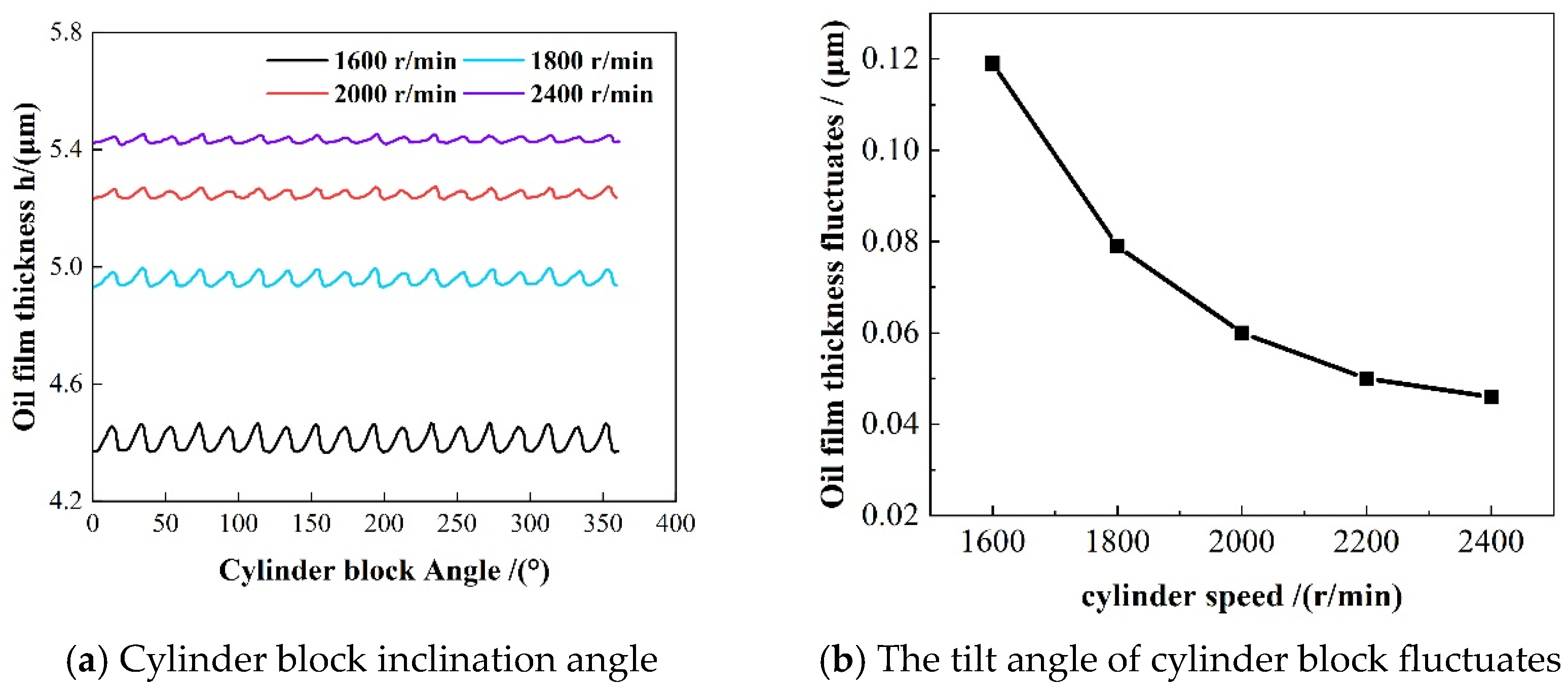
The cylinder speed is an important factor in the dynamic pressure support effect of the oil film of the flow distribution pair [32], and the lubrication performance of the oil film of the flow distribution pair can be improved by increasing the rotation speed within a limited range. Figure 2 and Figure 3 show the changes in the oil film thickness of the flow distribution pair and the cylinder tilt angle of the cylinder block in a motion period under different cylinder block speeds, in which the thickness of the oil film and the tilt angle of the cylinder block change periodically with the angle of the 40° cylinder block. In addition, it can be seen from the figure that the cylinder speed increases from 1600 r/min to 2400 r/min, and the average oil film thickness of the flow distribution pair is 4.48/4.94/5.29/5.47 μm, respectively, and the average oil film thickness fluctuates with amplitudes of 0.118 μm, 0.078 μm, 0.059 μm and 0.046 μm. That is, under the same working pressure, the average oil film thickness rises as the rotational speed increases, and the fluctuation amplitude of the average oil film thickness decreases with the increase in rotational speed. Under the rotation speed of each cylinder block, the average tilt angle of the cylinder block is 4.78 × 10⁻³/3.34 × 10−3/2.21 × 10−3/1.49 × 10−3°, and the fluctuation amplitude of the tilt angle of the cylinder block is 2.45 × 10⁻⁴/1.37 × 10−4/0.56 × 10−4/0.47 × 10−4°. That is, under the same working pressure, the tilt angle of the cylinder block decreases with the increase in the speed, and the fluctuation amplitude of the tilt angle of the cylinder block also decreases.
It can be seen from the figure that the minimum thickness of the oil film of the flow distribution pair increases with the increase in the cylinder speed, indicating that the possibility of wear of the flow distribution pair decreases with the increase in the cylinder speed. In addition, the variation amplitude of oil film thickness and tilt angle of the cylinder block decreases with the increase in cylinder speed, indicating that the increase in cylinder speed in a limited range can enhance the running stability of the cylinder block.
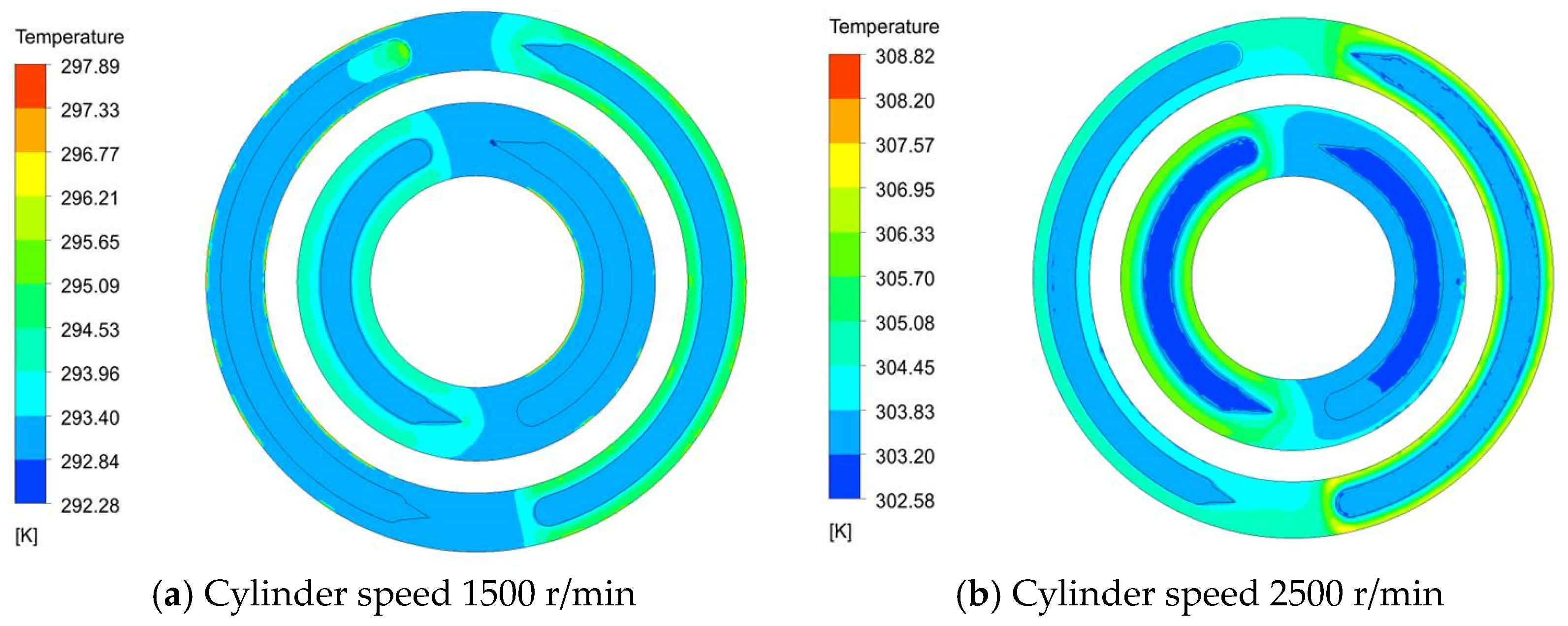
Figure 4 shows the effect of different cylinder speeds on oil film temperature distribution under identical working pressure. As can be seen from the figure, when the cylinder speed increases from 1500 r/min to 2500 r/min, the overall temperature of the oil film of the flow distribution pair increases, and the cylinder speed significantly affects the temperature distribution of the flow distribution pair, mainly because the viscous friction dissipation of the oil film of the flow distribution pair is proportional to the square of the cylinder speed. The geometric increase in viscous frictional dissipation will cause the oil film temperature to increase sharply, especially in the outer sealing belt of the oil film. where the temperature change is the largest, and the maximum temperature of the oil film increases from 296.3 K to 307.2 K. In addition, the increase in cylinder speed has little impact on the oil film pressure distribution and external load force, and the elastic deformation is almost unchanged, making the heat and flow be carried away by the inner and outer row sealing belt through the oil film. Therefore, it is clear that the increase in cylinder speed affects the oil film temperature primarily by enhancing viscous friction dissipation. With the increase in the cylinder speed of the flow distribution pair, it can be found that the temperature of the transition area and the low-pressure area of the flow distribution pair increases obviously. This is due to the fact that as the cylinder speed increases, the overall temperature of the flow distribution pair oil film rises, and the heat transfer inside the oil film is enhanced. The heat transfer from the high-pressure area of the flow distribution pair to the low-pressure area through the transition area increases, resulting in the temperature increase in the transition area and the low-pressure area. Therefore, selecting the appropriate cylinder speed can effectively control the oil film temperature between the flow distribution pair, reduce the friction and wear of the flow distribution pair, and improve the service life of the balanced double-row axial piston pump.
Figure 5 illustrates how varying cylinder speeds affect the friction and leakage characteristics of the oil film in the flow distribution pair. As shown in Figure 5a, under the same working pressure, the rise in cylinder speed will result in an increase in friction torque, and as the speed increases, the increase trend of oil film friction torque is larger and larger. In addition, it is evident that, in comparison to elastic deformation alone, the friction torque under thermal deformation and elastic deformation is relatively increased. This is due to the fact that accounting for the increase in thermal deformation will reduce the oil film thickness of the flow distribution pair, resulting in the increase in the shear stress of the oil film and the increase in the friction force of the oil film, and the friction torque will increase accordingly. As can be seen from Figure 5b, when the working pressure remains unchanged, the leakage amount of the oil film of the flow distribution pair increases with the increase in the cylinder speed. This is because the amount of leakage from the flow distribution pair is directly proportional to the radial velocity of the oil, and the radial velocity of the oil increases with the speed, so the leakage amount will increase with the increase in the speed. In addition, compared with only considering elastic deformation, the leakage amount under elastic deformation and thermal deformation is relatively reduced. This is because the consideration of increasing thermal deformation will reduce the thickness of the oil film of the flow distribution pair and the radial velocity of the oil film, resulting in the reduction in the leakage amount of the flow distribution pair.

3.2. Influence of Working Pressure on Thermal Elastohydrodynamic Lubrication Characteristics of the Flow Distribution Pair

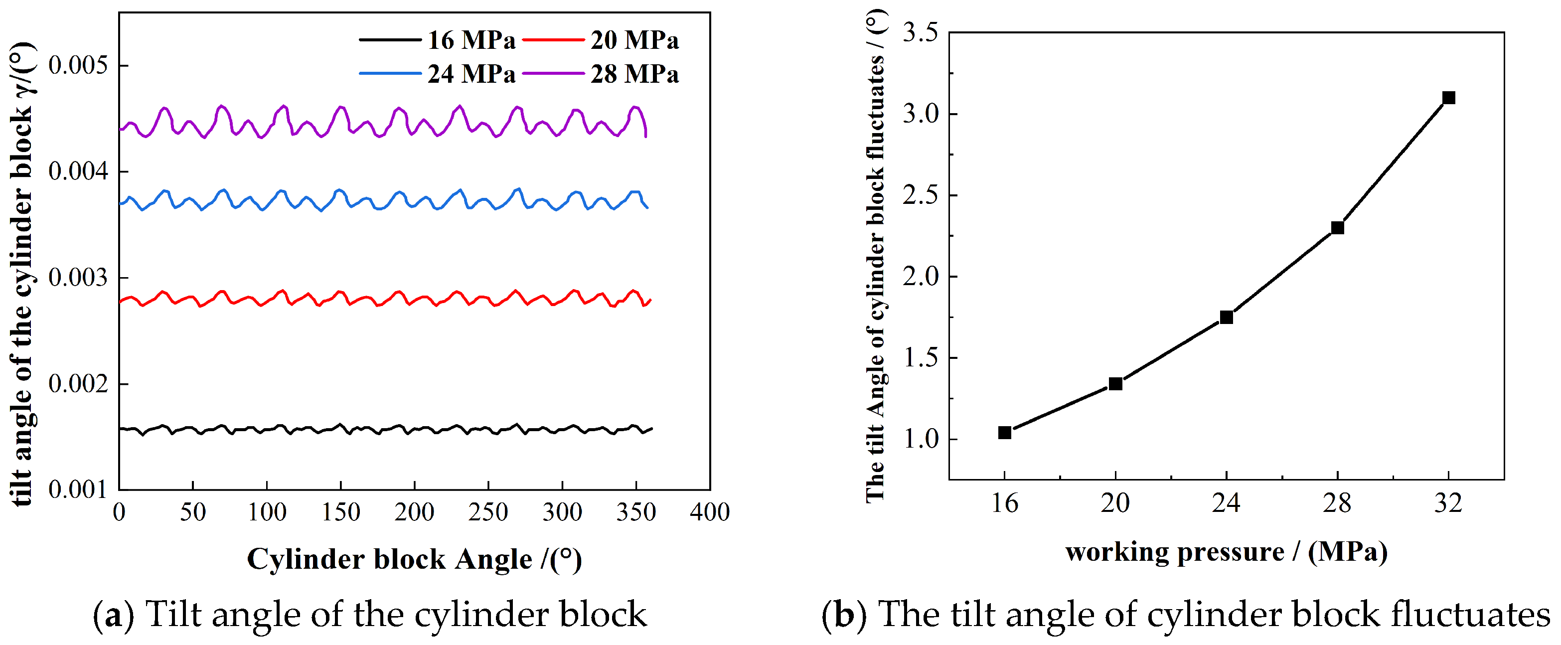
Figure 6 and Figure 7 show the changes in the oil film thickness of the piston pump distribution pair and the tilt angle of the cylinder block in a cycle under different working pressures. As shown in the figure, the working pressure varies from 16 MPa to 28 MPa, the average oil film thickness of the flow distribution pair is 5.87/5.42/4.74/4.26 μm, and the fluctuation amplitude of the average oil film thickness is 0.052 μm, 0.052/0.076/0.093/0.114 μm, respectively. In other words, the average oil film thickness diminishes as the working pressure rises, while the fluctuation amplitude of the average oil film thickness increases with higher working pressure. Under each working pressure, the average inclination tilt angle of the cylinder block is 1.71 × 10⁻³/2.89 × 10−3/3.82 × 10−3/3.82 × 10−3/4.46 × 10−3, and the fluctuation amplitude of the tilt angle of the cylinder block is 1.14 × 10⁻³/1.43 × 10−3/1.78 × 10−3/2.39 × 10−3, respectively. That is, the increase in working pressure will cause the tilt angle of the cylinder block to increase, and the fluctuation amplitude of the tilt angle of the cylinder block will also increase with the increase in the working pressure.
Parameters such as the oil film thickness of the flow distribution pair and the tilt angle of the cylinder block comprehensively reflect the dynamic pressure support effect of oil film of the flow distribution pair. As can be seen from the figure, when the working pressure increases, the tilt angle of the cylinder block increases, indicating that the static pressure support of the oil film of the flow distribution pair is not enough to balance the external load with the dynamic pressure support at this time, so sufficient dynamic pressure support is required, therefore the oil film thickness of the flow distribution pair decreases, and the smaller minimum value of the oil film thickness means that wear may occur. In addition, it can be found that when the working pressure increases, the microvibration of the piston pump cylinder becomes more obvious, indicating that the squeeze support effect of the oil film of the flow distribution pair will be enhanced with the increase in the working pressure, which is consistent with the change in the dynamic pressure support effect of the oil film. This phenomenon proves that the dynamic pressure support of the oil film of the flow distribution pair achieves the dynamic balance of the piston pump block together with the squeeze support. At the same time, the variation amplitude of the oil film thickness and the tilt angle of the cylinder block increases with the increase in working pressure, indicating that the stability of the cylinder block during the running cycle gradually decreases with the increase in working pressure.
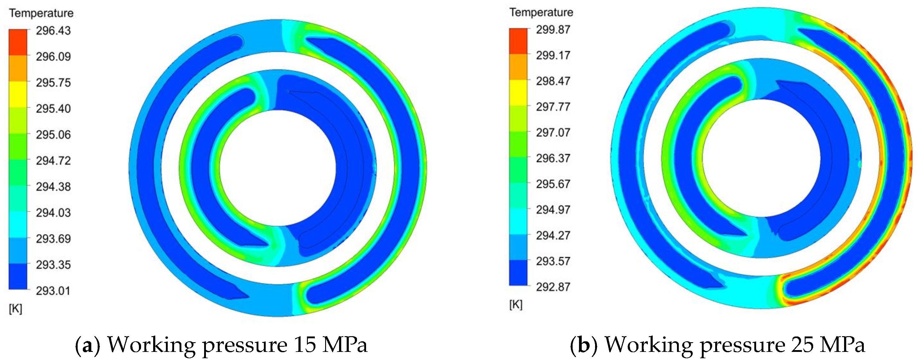
Figure 8 shows the influence of working pressure on the oil film temperature of the flow distribution pair under the same cylinder speed. As can be seen from the figure, the effect of working pressure on the oil film temperature is relatively minor: the increase in working pressure mainly affects the oil film pressure distribution at the oil outlet of the inner and outer oil film of the flow distribution pair. When the working pressure increases, the radial differential pressure flow velocity of the oil film on the oil discharge side of the flow distribution pair increases, as well as the oil film viscosity and elastic deformation. The increase in the radial differential pressure flow velocity of the oil film will lead to the increase in heat carried away through the sealing belt, while the increase in the oil film viscosity will increase the heat generation. Under the combined action of these two factors, the temperature of the oil film of the flow distribution pair increases, especially on the oil discharge side of the outer oil film of the flow distribution pair, the temperature changes the most, and the highest oil film temperature increases from 295.5 K to 299.3 K. In addition, it can be seen that with the increase in working pressure, the oil film temperature in the high-pressure region of the flow distribution pair will gradually transfer to the low-pressure region through the transition region, making the temperature of the transition region and the low-pressure region relatively increase. Therefore, choosing the right working pressure is very important to control the oil film temperature of the flow distribution pair, so as to ensure the structure and working performance of the flow distribution pair.
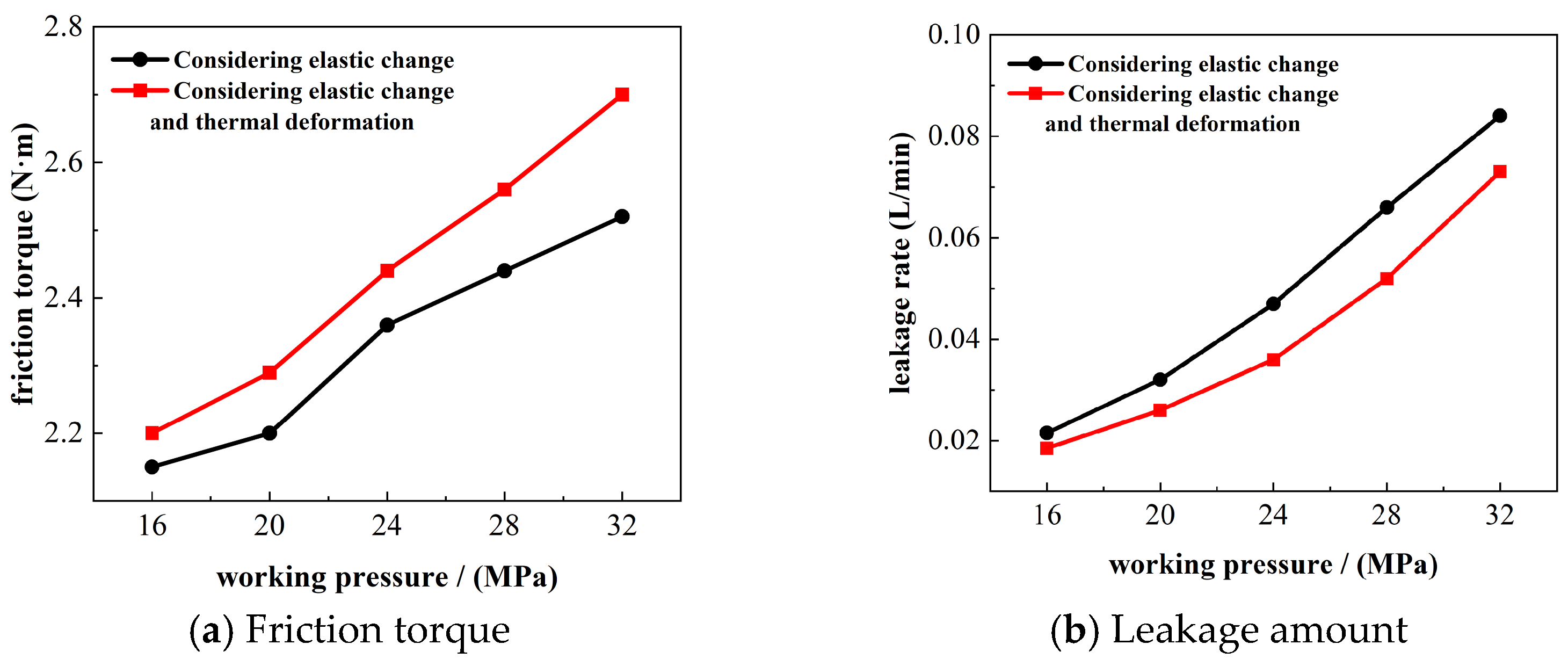
Figure 9 illustrates how varying working pressures affect the friction and leakage characteristics of the oil film in the flow distribution pair. As observed in Figure 9a, when the cylinder block speed remains unchanged, the friction torque of the oil film of the flow distribution pair increases with the increase in the working pressure. This is because the increase in the working pressure of the piston pump will lead to the decrease in the oil film thickness of the flow distribution pair, which will lead to the increase in the shear stress of the oil film and the increase in the friction force of the oil film, and the friction torque of the oil film of the flow distribution pair will also increase. In addition, with the increase in working pressure, due to the combined action of the radial differential pressure flow velocity of the oil film, the elastic deformation, and the oil viscosity of the oil film, the oil film temperature increases, the thermal deformation of the oil film increases, the thickness of the oil film decreases, and the friction force increases. As a result, the friction torque of the oil film of the flow distribution pair will increase when considering the thermal deformation and elastic deformation compared with only considering the elastic deformation. The variation range of friction torque is also gradually increased compared to only considering elastic deformation.
As can be seen from Figure 9b, when the cylinder block speed remains unchanged, the leakage of the oil film of the flow distribution pair increases with the increase in the working pressure. This is because the increase in the working pressure will result in the increase in the radial differential pressure flow velocity of the oil film of the flow distribution pair, resulting in the increase in leakage. In addition, thermal deformation will reduce the thickness of the oil film of the flow distribution pair, and the radial flow velocity of the oil film will decrease, resulting in a decrease in leakage, and the reduction range will gradually increase with the increase in working pressure.

3.3. Influence of Temperature on Thermal Elastohydrodynamic Lubrication Characteristics of the Flow Distribution Pair

As we all know, temperature has a very important impact on the viscosity of the lubricant film; the increase in temperature will cause the viscosity of lubricating oil to decrease, and the bearing stiffness of lubricant film will decrease. As a result, examining how varying temperature conditions affect the lubrication performance of the oil film in the flow distribution pair is crucial.
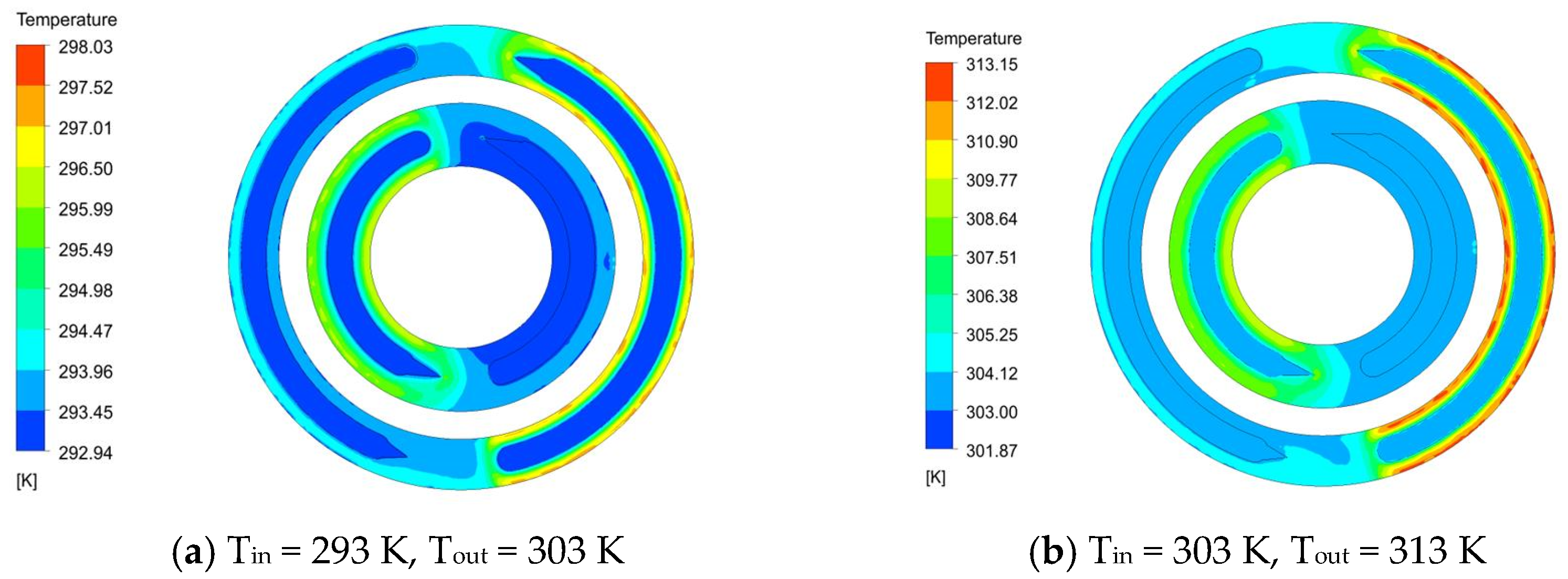
Figure 10 shows the temperature distribution of the flow distribution pair under different temperature conditions. As can be seen from the figure, when the temperature condition of the flow distribution pair is Tin = 293 K, Tout = 303 K increases, Tin = 303 K, Tout = 313 K, the overall oil film temperature of the flow distribution pair increases and the rising trend is obvious, and the maximum oil film temperature rises from 297.6 K to 312.9 K. This is because with the increase in the working temperature condition of the flow distribution pair, the oil film thickness of the flow distribution pair will become thinner, this will result in a rise in the viscous friction loss of the oil film, which in turn leads to increased heat generation within the oil film. Moreover, the gradient between the heat of the oil film energy and the temperature of the working environment of the piston pump will decrease, furthermore, the heat dissipation capacity of the oil film will diminish. Under the combined action, the oil film temperature of the flow distribution pair will increase. Moreover, it is evident that as the working temperature conditions of the flow distribution pair rise, the temperature of the transition region and the low-pressure region of the flow distribution pair increases. This is because the heat transfer between the regions inside the oil film of the flow distribution pair increases with the increase in temperature, and the heat transfer from the high-pressure region of the flow distribution pair to the low-pressure region increases through the transition region, so the temperature of the transition region and the low-pressure region increases as a whole.
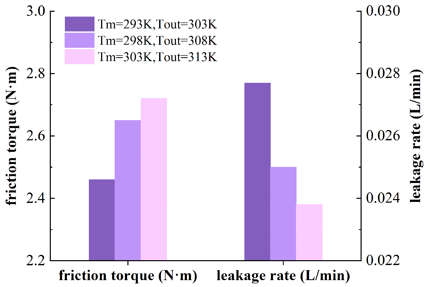
Figure 11 illustrates how the lubrication characteristics of the oil film are affected by various temperature conditions. As depicted in the figure, the friction torque of the oil film in the flow distribution pair rises with an increase in temperature When the temperature condition is increased from Tin = 293 K, Tout = 303 K to Tin = 298 K, Tout = 308 K, the friction torque of the oil film increases by 6.48%; when the temperature condition is increased from Tin = 298 K, Tout = 308 K to Tin = 303 K, Tout = 313 K, the frictional torque of oil film increases by 3.42%, that is, the increase in frictional torque of oil film of the flow distribution pair decreases with the increase in temperature. As the temperature rises, the leakage decreases. When the temperature increases from Tin = 293 K, Tout = 303 K to Tin = 298 K, Tout = 308 K, the oil film leakage decreases by 9.45%; when the temperature increases from Tin = 298 K, Tout = 308 K to Tin = 303 K, Tout = 313 K, the oil film leakage decreases by 4.02%, that is, with the increase in temperature, the oil film leakage reduction decreases. The above results are mainly because the increase in temperature conditions will cause the decrease in the oil film thickness of the flow distribution pair, additionally, a reduction in oil film thickness will result in an increase in shear stress within the oil film, leading to heightened oil film friction, thus increasing the friction torque. In addition, the decrease in the oil film thickness will lead to the decrease in the pressure difference effect of the oil film of the flow distribution pair, the radial velocity of the oil film decreases, and the leakage also decreases.

3.4. Influence of Sealing Belt Width on Thermal Elastohydrodynamic Lubrication Characteristics of Flow Distribution Pair

The inner and outer width of the sealing belt is an important structural size of the distribution pair, this significantly impacts the friction and lubrication properties of the flow distribution pair. An appropriate sealing bandwidth can ensure that the flow distribution pair can have enough oil film support force, and can ensure that its leakage is not too large. In order to study the influence of the inner and outer sealing bandwidths on the oil film lubrication characteristics of the flow distribution pair of the balanced double-row axial piston pump, the following five widths of sealing belts were compared with their structural parameters presented in Table 3.
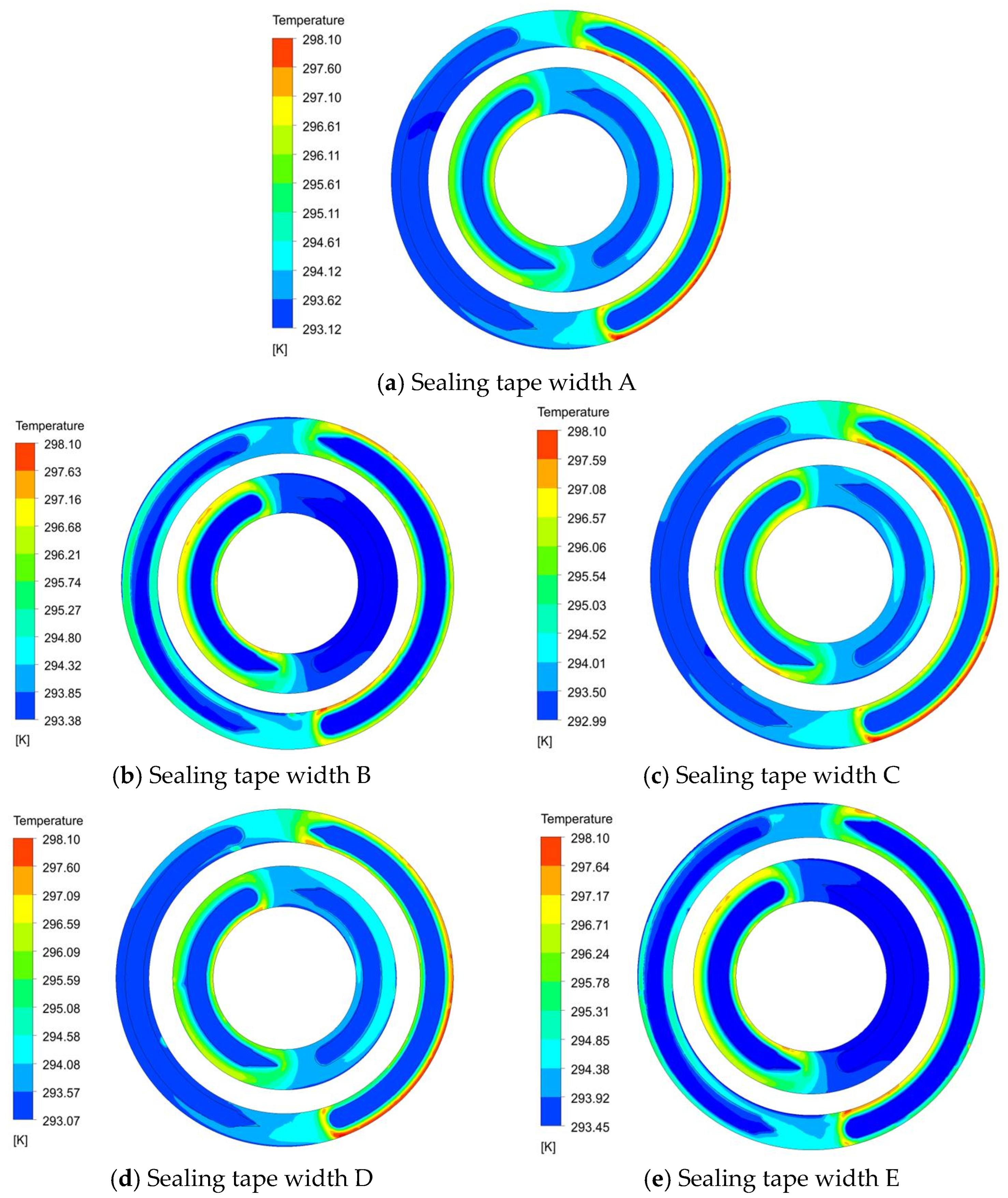
Figure 12 shows the influence of different inner and outer seal bandwidths on the oil film temperature distribution of the flow distributor pair. By comparing (a) with (b), (c), (d), and (e) in Figure 12, it can be found that unidirectional reduction in the width of the inner and outer sealing bands of the inner and outer rows of the flow distribution pair can bring about a slight decrease in the oil film temperature, mainly because the reduction in the sealing band width will reduce the contact area of the oil film, thus reducing the total viscous friction dissipation of the flow distribution pair. The production of heat inside the oil film is also reduced. In addition, under the reduction in the same sealing band width, the degree of oil film temperature drop in the outer sealing band is larger for the inner sealing band, and the degree of temperature drop in the outer sealing band is greater than that in the inner sealing band, which is due to the greater reduction in the outer oil film contact area and the greater reduction in viscous friction dissipation under the reduction in the same sealing band width.
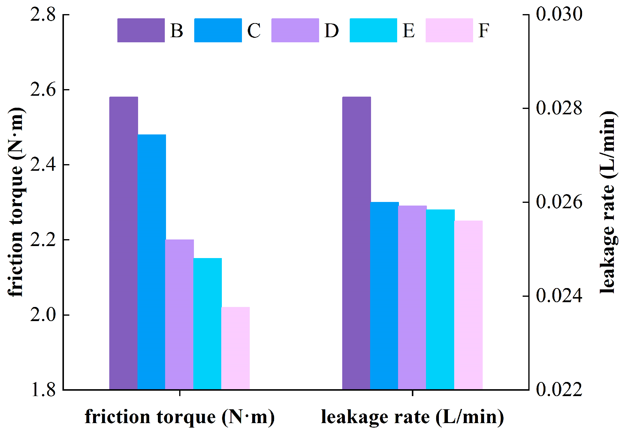
The design of the distribution plate in the balanced double-row axial piston pump is complex, and the width of the sealing belt in the inner and outer rows affects the flow field distribution and lubrication state in their respective regions. Figure 13 shows the friction torque and leakage of the flow distribution pair at different sealing bandwidths. As can be seen from the figure, regardless of whether the inner sealing belt or the outer sealing belt, the friction torque decreases with the decrease in the width of the sealing belt, which is because the decrease in the width of the sealing belt will reduce the total contact area of the oil film, resulting in the friction torque of the flow distribution pair being reduced. When the width of the sealing band is reduced to 1 mm, the friction torque is reduced by 4.27% by reducing the inner row inner sealing band, 14.57% by reducing the inner row outer sealing band, 17.01% by reducing the outer row inner sealing band, and 21.53% by reducing the outer row outer sealing band. It can be observed that when the width of the same sealing belt is decreased, the friction torque of the outer row and outer sealing belt decreases more significantly than that of the inner row and inner sealing belt. This is because the contact area of the outer oil film is reduced to a greater extent under the same sealing belt width, so the friction torque is reduced more.
The figure illustrates that the leakage of the flow distribution pair is inversely correlated with the width of the sealing belt. Reducing the width of the sealing belt will reduce the leakage. When the width of the sealing belt is reduced by 1 mm, reducing the inner row inner sealing belt reduces the leakage by 8.48%, reducing the inner row outer sealing belt reduces the leakage by 8.49%, reducing the outer row inner sealing belt reduces the leakage by 8.51% and reducing the outer row outer sealing belt reduces the leakage by 8.54%. Compared with the oil film friction torque, the greater reduction is when the oil film friction torque is on the outside. Regardless of whether the inner sealing belt or the outer sealing belt, there is no significant difference in the reduction in the oil film leakage of the sealing belt under the same width. In summary, the friction torque and leakage of the flow distribution pair are related to the sealing band bandwidth, therefore, designing an appropriate sealing band width is crucial for enhancing the mechanical conversion efficiency of the pump.

4. Discussion

Reference [33] theoretically deduced that the main loss is viscous friction loss, and demonstrated the influence of working pressure, speed, and other parameters on the lubrication characteristics.
According to the analysis of Figure 2, Figure 3, Figure 4 and Figure 5, it can be seen that in a motion cycle, the oil film thickness and cylinder tilt angle of the piston pump port pair change periodically with a 40° rigid body rotation angle. This 40° periodic change is also due to the number of plungers in the plunger pump, set to nine in this paper. The minimum thickness of the oil film of the port pair increases with the increase in the cylinder speed, indicating that with the increase in the cylinder speed, the possibility of wear of the port pair decreases. In addition, the variation range of oil film thickness and cylinder tilt angle decreases with the increase in rotational speed, which indicates that the increase in cylinder speed in a limited range can enhance the operation stability of cylinder. However, an increase in rotational speed will result in a rise in the overall temperature of the oil film, leading to greater wear on the port plate pair and an increase in oil film leakage. Thus, setting the cylinder speed at approximately 2400 r/min can enhance the operational stability of the rigid body under low leakage conditions, reduce wear on the port plate pair, and improve the service life of the plunger pump.
Based on the analysis of Figure 6, Figure 7, Figure 8 and Figure 9, it can be seen that with the increase in working pressure, the average oil film thickness decreases as the working pressure increases. while the rigid body inclination angle increases, and the fluctuation amplitude of both increases, which indicates that the increase in working pressure will lead to the decrease in the stability of rigid body operation. The increase in working pressure will also lead to the increase in friction torque and leakage of oil film, and the temperature will also increase slightly. Therefore, when the working pressure is not more than 16 MPa, the operation of the cylinder block will be more stable, which can better guarantee the structure and working performance of the port plate pair.
As observed in Figure 10 and Figure 11, the working temperature conditions of the port plate pair increase, the oil film temperature of the port plate pair will increase, the oil film thickness will become thinner, the friction torque of the oil film will increase, and the leakage will decrease. Table 1 and Figure 12 and Figure 13 show that the one-way reduction in the width of the inner and outer sealing belts of the port plate pair will lead to a slight decrease in the oil film temperature, but the decrease in the outer sealing belt is larger than that of the inner sealing belt. The reduction in the width of the sealing belt will also lead to the reduction in the friction torque. In comparison to the inner row, the friction torque of the outer sealing belt is reduced more significantly than that of the inner sealing belt. Additionally, the leakage of the port plate pair is inversely related to the width of the sealing strip; thus, reducing the width of the sealing strip will lead to a decrease in leakage. Therefore, a reasonable design of the sealing belt width will improve the mechanical conversion efficiency of the pump.

5. Conclusions

In this paper, a theoretical model for calculating the thermal elastohydrodynamic lubrication performance of the flow distribution pair of the balanced double-row axial piston pump is established. The influence of cylinder speed, working pressure, seal width, and temperature conditions on the oil film lubrication characteristics of the flow distribution pair has been quantitatively analyzed, leading to the following conclusions.
(1)
The oil film thickness of the flow distribution pair and the tilt angle of the cylinder block change periodically with 40° in a working cycle. The average oil film thickness of the flow distribution pair increases with the increase in the cylinder speed, and its fluctuation decreases. The tilt angle of the cylinder block and its fluctuation amplitude decrease with the increase in rotational speed. As the working pressure increases, the average oil film thickness decreases, while the variation in oil film thickness increases. The tilt angle of the cylinder block and its fluctuation amplitude increase with the increase in working pressure.
(2)
The increase in the cylinder speed will increase the friction torque of the flow distribution pair, increase the viscous friction dissipation, increase the heat production, and cause the oil film temperature to increase. An increase in rotational speed results in a thicker oil film, which enhances the radial velocity of the oil film and subsequently leads to increased leakage. The increase in working pressure will cause the decrease in oil film thickness, increase the shear stress of oil film, increase the friction force of oil film, increase the dissipation of viscous friction, and cause the increase in oil film temperature. The increase in pressure will cause the increase in radial pressure difference velocity of oil film and the increase in leakage.
(3)
Temperature is a crucial factor that influences the oil film lubrication performance of the flow distribution pair. When the working temperature of the piston pump increases, the oil film thickness decreases, the friction torque increases, and the oil film temperature increases. In addition, the oil film thickness decreases, the effect of the oil film pressure difference decreases, the radial flow rate decreases, and the leakage decreases.
(4)
The appropriate width of the sealing belt significantly impacts the lubrication performance of the flow distribution pair. Reducing the width of the sealing belt will cause the total contact area of the oil film to decrease, resulting in a decrease in the friction torque of the flow distribution pair and a decrease in the oil film temperature.

Author Contributions

H.D.: Conceptualization, funding acquisition, methodology, project administration, resources, supervision. B.G.: Data curation, formal analysis, investigation, methodology, software, validation, visualization, writing—original draft. Z.H.: Data curation, validation, writing—original draft. P.X.: Data curation, validation, writing—review and editing. P.Z.: Data curation, formal analysis, investigation, methodology, software, validation, visualization, writing—original draft. All authors have read and agreed to the published version of the manuscript.

Funding

This research received no external funding.

Data Availability Statement

Data will be made available on request.

Conflicts of Interest

The authors declare that they have no known competing financial interests or personal relationships that could have appeared to influence the work reported in this paper.

References

  1. Gao, X. Lubrication Characteristics Analysis of Four Valve Valve Axial Piston Pump Valve Pair. Master’s Thesis, Taiyuan University of Science and Technology, Tai Yuan Shi, China, 2021. Available online: https://link.cnki.net/doi/10.27721/d.cnki.gyzjc.2021.000227doi:10.27721/d.cnki.gyzjc.2021.00022 (accessed on 3 September 2024). [CrossRef]
  2. Tang, H.; Yin, Y.; Zhang, Y.; Li, J. Parametric analysis of thermal effect on hydrostatic slipper bearing capacity of axial piston pump. J. Cent. South Univ. 2016, 23, 333–343. [Google Scholar] [CrossRef]
  3. Ye, S.; Zhang, J.; Xu, B. Noise reduction of anaxial piston pump by valve plate optimization. Chin. J. Mech. Eng. 2018, 31, 1–16. [Google Scholar] [CrossRef]
  4. Zhang, S. Cavitation Research and Structural Transformation of Valve Plate of Axial Piston Pump. Master’s Thesis, Lanzhou University of Technology, Lanzhou, China, 2021. [Google Scholar]
  5. Yan, W. Study on Anti-Overturning Stability and Oil Film Lubrication Characteristics of Axial Piston Pump. Ph.D. Thesis, Harbin University of Technology, Harbin, China, 2020. [Google Scholar]
  6. Wang, Y.; Wang, Z.; Zhang, J. The influence of flow distribution pair parameters on friction performance of piston pump under thermal-fluid-solid coupling. Lubr. Seal. 2021, 46, 65–71. [Google Scholar]
  7. Baker, J.; Ivantysynova, M. Power loss in the lubricating gap between cylinders block and valve plate of swash plate type axial piston machines. Int. J. Fluid Power 2009, 10, 29–43. [Google Scholar]
  8. Li, W.; Liu, X.; Long, T.; Guo, F. Numerical Analysis of Non-Newtonian Elliptic Contact Thermoelastohydrodynamic Lubrication under Spinning and Sliding Conditions. Lubrication and Sealing, 1–10 [2024-10-01]. Available online: https://kns.cnki.net/kcms2/article/abstract?v=KzQCREa95bEa-KEgBmdHHReop7o9MRx-bnEauMQyMT6s7Bf13QvH7pInfebJry4jufamNN3Js8W59PpjP2xSOtYGPpzCJG3ug9x3Itfntu2XhHKNyeeUmRyDpyzoTaTneAUF_N2IqNoKyZkzimEGse_ydh8GH2pRMF0TEDp_j1a92Wt6Gxh1XwYgPewOiyWK&uniplatform=NZKPT&language=CHS (accessed on 3 September 2024).
  9. Chacon, R.; Ivantysynova, M. An Investigation of the Impact of Micro Surface on the Cylinder Block/Valve Plate Interface Performance. In Proceedings of the 8th FPNI Ph.D Symposium on Fluid Power, Lappeenranta, Finland, 11–13 June 2014; ASME: NEW York, NY, USA, 2014; p. V001T02A006. [Google Scholar] [CrossRef]
  10. Hu, S.; Wang, Z.; Ji, H.; Yang, J.; Zhang, H. Thermal-fluid-solid coupling lubrication characteristics of micro-textured port plate. Hydraul. Pneum. 2019, 12, 38–45. [Google Scholar]
  11. Ki Kim, J.; Jung, J.Y. Measurement of Fluid Thickness on the Valve Plate in Oil Hydraulic Axial Piston Pumps (Ⅱ): Spherical Design Effects. J. Mech. Sci. Technol. 2005, 19, 655–663. [Google Scholar] [CrossRef]
  12. Han, L.; Wang, S.; Zhang, C. A partial lubrication model between valve plate and cylinder block in axial piston pumps. Proc. Inst. Mech. Eng. Part C J. Mech. Eng. Sci. 2015, 229, 3201–3217. [Google Scholar] [CrossRef]
  13. Wang, Z.; Hu, S.; Ji, H.; Wang, Z.; Liu, X. Analysis of lubricating characteristics of valve plate pair of a piston pump. Tribol. Int. 2018, 126, 49–64. [Google Scholar] [CrossRef]
  14. Zhang, J.; Wang, Z.; Han, B.; Sun, L.; Gao, W. Lubrication characteristics of piston pump/motor port plate pair based on fractal theory. Lubr. Seal. 2023, 48, 68–74. [Google Scholar]
  15. Hou, L.; Lai, W.; Cui, K.; Ye, S.; Guo, Z.; Bu, X. Modeling and analysis of oil film lubrication characteristics of plane port plate pair of axial piston motor. J. South China Univ. Technol. (Nat. Sci. Ed.) 2021, 49, 99–109. [Google Scholar]
  16. Hu, J.; Zou, Y.; Li, X.; Lin, S. Effect of elastic deformation on lubrication characteristics of port plate pair in axial piston pump. Agric. Eng. J. 2009, 25, 114–118. [Google Scholar]
  17. Lu, R.; Tang, W.; Huang, Q.; Xie, J. An Improved Load Distribution Model for Gear Transmission in Thermal Elastohydrodynamic Lubrication. Lubricants 2023, 11, 177. [Google Scholar] [CrossRef]
  18. Xu, Y.; Deng, X.; Wang, S.; Ren, J.; Yang, H. Thermal elastohydrodynamic lubrication analysis of the roller enveloping hourglass worm drives considering the roller self-rotation behavior. Tribol. Int. 2024, 200, 110142. [Google Scholar] [CrossRef]
  19. Bergada, J.M.; Kumar, S.; Davies, D.L.; Watton, J. A complete analysis of axial piston pump leakage and output flow ripples. Appl. Math. Model. 2012, 36, 1731–1751. [Google Scholar] [CrossRef]
  20. Tang, H.; Ren, Y.; Xiang, J. A novel model for predicting thermoelastohydrodynamic lubrication characteristics of slipper pair in axial piston pump. Int. J. Mech. Sci. 2017, 124–125, 109–121. [Google Scholar] [CrossRef]
  21. Deng, H.; Wang, C.; Zhang, L. Study on flow pulsation of balanced two-row axial piston pump. J. Agric. Mach. 2014, 45, 305–309. [Google Scholar]
  22. Wang, Y.; Tang, W.; Chen, Y.; Wang, T.; Li, G.; Ball, A.D. Investigation into the meshing friction heat generation and transient thermal characteristics of spiral bevel gears. Appl. Therm. Eng. 2017, 119, 245–253. [Google Scholar] [CrossRef]
  23. Chen, J.; Liu, X.; Pei, X.; Wang, H. Effect of Viscous and Compressive Properties of Ionic Liquid Additives on Thermoelastohydrodynamic Lubrication. Lubrication and Sealing, 1–15 [2024-10-01]. Available online: https://kns.cnki.net/kcms2/article/abstract?v=KzQCREa95bFlYpN4H4fsaTBTtRFhR4xneXRN3G4balP1QVqQVAwgT10W4y37EoPkUzFnmdcSIkmoOOklsBhTIR4MSizuQHiqgZnDIDX98u0SK3P0WHucgHxmtSv79cpHnekAjXGI4aUzRSNnhVOJa6kPJLc2w_fbMxzypSRjnF3WJ_th2-nswW_IRARMcBPn&uniplatform=NZKPT&language=CHS (accessed on 3 September 2024).
  24. Li, C.; Jiang, T.; Liu, C.; Xu, H.; Shi, G. Investigation of the leakage in the flow distribution pair of radial piston hydraulic motors through CFD analysis and experiments. Flow Meas. Instrum. 2024, 96, 102555. [Google Scholar] [CrossRef]
  25. Zhao, K.; Wang, C.; He, T.; Luo, G.; Qin, Y.; Fang, S. Theoretical and experimental study on lubrication and friction of slipper pair of valve distribution piston pump based on FVM-TRD coupling method. Tribol. Int. 2024, 194, 109456. [Google Scholar] [CrossRef]
  26. Pan, Y.; Chen, A.; Wang, Z. Fluid Dynamic Characteristics and Flow Distribution Structure Optimization of Axial Piston Pump Considering Cavitation Bubble Evolution. J. Appl. Fluid Mech. 2021, 14, 1603–1616. [Google Scholar]
  27. Ghiaasiaan, S. Convective Heat and Mass Transfer; Cambridge University Press: Cambridge, UK, 2011; p. 477. [Google Scholar]
  28. Gan, L.; Xiao, K.; Wang, J.; Cao, W.; Wang, J. A numerical method to investigate the temperature behavior of spiral bevel gears under mixed lubrication condition. Appl. Therm. Eng. 2019, 147, 866–875. [Google Scholar] [CrossRef]
  29. Ivantysyn, J.; Ivantysynova, M. Hydrostatic Pumps and Motors: Principle, Design, Performance, Modeling, Analysis, Control and Testing; Tech Books International: New Delhi, India, 2002. [Google Scholar]
  30. Ye, S.; Lai, W.; Hou, L.; Bu, X. Modeling and experimental verification of lubrication characteristics of conical cylinder block spherical port pair. China Mech. Eng. 2022, 33, 2420–2428+2436. [Google Scholar]
  31. Hamrock, B.; Schmid, S.; Jacobson, B. Fundamentals of Fluid Film Lubrication; McGraw-Hill: New York, NY, USA, 2004. [Google Scholar]
  32. Richardson, D.; Sadeghi, F.; Rateick, R.G., Jr.; Rowan, S. Experimental and Analytical Investigation of Floating Valve Plate Motion in an Axial Piston Pump. Tribol. Trans. 2017, 60, 537–547. [Google Scholar] [CrossRef]
  33. Zhao, Y.; Zhou, J.; Jing, C.; Wei, C. Dynamic pressure support characteristics of slotted port pair of axial piston pump. J. Harbin Inst. Technol. 2018, 50, 169–174. [Google Scholar]
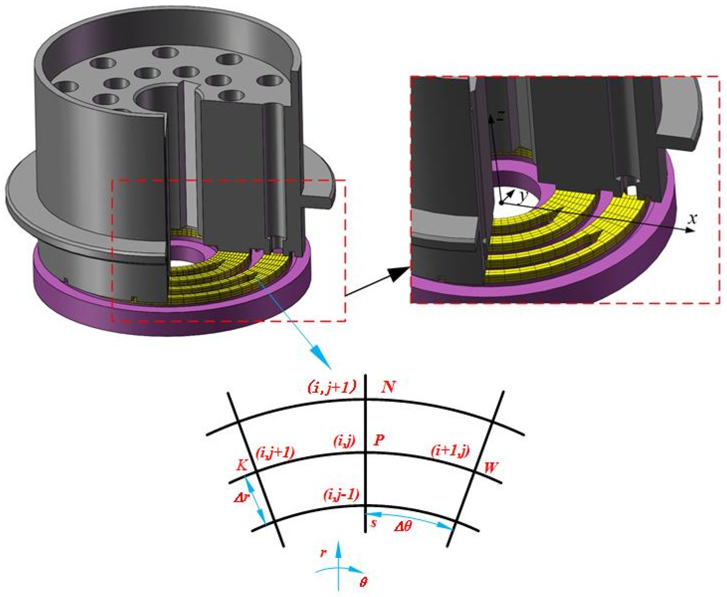
Figure 1. Schematic diagram of oil film grid division and central difference scheme of the flow distribution pair.
Lubricants 12 00342 g001
Figure 2. Influence of cylinder speed on oil film thickness and its fluctuation of flow distribution pair.
Lubricants 12 00342 g002
Figure 3. Influence of cylinder speed on tilt angle of the cylinder block and its fluctuation.
Lubricants 12 00342 g003
Figure 4. Oil film temperature distribution under different cylinder speeds.
Lubricants 12 00342 g004
Figure 5. Oil film lubrication characteristics under different cylinder speeds.
Lubricants 12 00342 g005
Figure 6. Influence of working pressure on the oil film thickness and its fluctuation of the flow distribution pair.
Lubricants 12 00342 g006
Figure 7. Influence of working pressure on the tilt angle of cylinder block and its fluctuation.
Lubricants 12 00342 g007
Figure 8. Oil film temperature distribution under different working pressures.
Lubricants 12 00342 g008
Figure 9. Oil film lubrication characteristics under different working pressures.
Lubricants 12 00342 g009
Figure 10. Temperature distribution of oil film under different temperature conditions.
Lubricants 12 00342 g010
Figure 11. Lubrication characteristics of oil film under different temperature conditions.
Lubricants 12 00342 g011
Figure 12. Oil film temperature distribution under different sealing bandwidths.
Lubricants 12 00342 g012
Figure 13. Lubrication characteristics of oil film at different sealing bandwidths.
Lubricants 12 00342 g013
Table 1. Calculation parameters.
ParameterNumerical Value
Viscous draining pressure ph20 MPa
Fuel inlet pressure pt0.2 MPa
Block rotation speed n2000 r/min
Oil inlet temperature Tin293 K
Oil outlet temperature Tout303 K
Specific heat capacity of lubricating oil cp1885 J·kg−1·K−1
Thermal conductivity of lubricating oil0.14 W·m−1·K−1
Viscosity-pressure coefficient of lubricating oil2.2 × 108 Pa−1
Viscosity-temperature coefficient of lubricating oil0.047 K−1
Table 2. Material properties of cylinder block and valve plate.
PartCylinder BlockPlate Type Rheostat Valve
Material42CrMo steelHMn58-2
Elastic modulus (Pa)2.12 × 10111.05 × 1011
Poisson ratio0.2800.350
Density ρ (kg/m3)78508410
Thermal expansion coefficient (K−1)1.10 × 10−51.90 × 10−5
Specific heat (J·kg−1·K−1)460394
Thermal conductivity (W·m−1·K−1)42.092.8
Table 3. Structural parameters of sealing belt width.
ABCDE
Inner sealing bands of the
inner rows/(mm)
3.52.53.53.53.5
Outer sealing bands of the
inner rows/(mm)
3.53.52.53.53.5
Inner sealing bands of the
outer rows/(mm)
2.52.52.51.52.5
Outer sealing bands of the
outer rows/(mm)
2.52.52.52.51.5
Disclaimer/Publisher’s Note: The statements, opinions and data contained in all publications are solely those of the individual author(s) and contributor(s) and not of MDPI and/or the editor(s). MDPI and/or the editor(s) disclaim responsibility for any injury to people or property resulting from any ideas, methods, instructions or products referred to in the content.