Article

Tribological Performance of a Plasma Electrolytic Oxidation-Coated Mg Alloy in Graphene-Incorporated Ethanol

1
Tribology of Materials Research Centre, Department of Mechanical, Automotive and Materials Engineering, University of Windsor, Windsor, ON N9B 3P4, Canada
2
Department of Metallurgical and Materials Engineering, Istanbul Technical University, Istanbul 34467, Turkey
*
Author to whom correspondence should be addressed.
Lubricants 2024, 12(1), 9; https://doi.org/10.3390/lubricants12010009
Submission received: 31 October 2023 / Revised: 13 December 2023 / Accepted: 19 December 2023 / Published: 28 December 2023
(This article belongs to the Special Issue Plasma Surface Treatments for Wear and Corrosion Protection)

Abstract

:
This study investigated the friction and wear characteristics of a plasma electrolytic oxidation (PEO)-coated Mg–Al alloy (AZ31) in sliding contact against steel using graphene nanoplatelets (GNPs) containing ethanol as a lubricant. The results revealed that the typically high coefficient of friction (COF) of PEO-coated surfaces under dry sliding (0.74) was notably reduced to 0.18 during the sliding tests conducted in GNP-free ethanol. When the ethanol contained 5 × 10⁻⁴ wt.% GNPs, the COF of the uncoated AZ31 alloy further dropped to 0.17. The PEO-coated surfaces achieved a significantly lower COF of 0.07 and demonstrated a marked reduction in wear rate, attributed to the formation of a tribolayer incorporating graphene. These findings highlight the significant potential of GNP-incorporated ethanol to improve the tribological performance of PEO-coated AZ31, presenting a promising avenue for advancing lightweight, sustainable, and efficient automotive technologies.

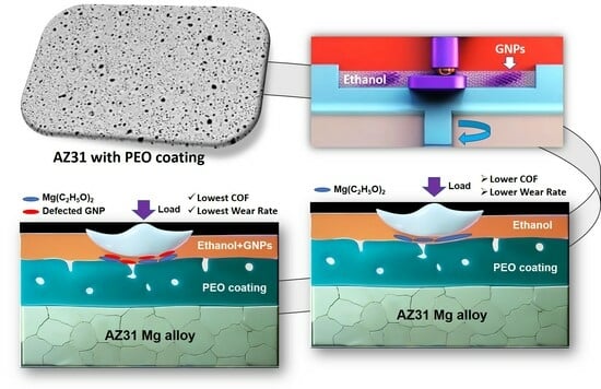
Graphical Abstract

1. Introduction

The plasma electrolytic oxidation (PEO) process, also known as micro-arc oxidation (MAO), is a coating technique that is particularly effective in enhancing the wear and corrosion resistance of lightweight metals, such as magnesium (Mg), aluminum (Al), and titanium (Ti), and this enhancement is achieved through electrochemical reactions that take place in alkaline and molten salt electrolyte environments [1,2,3,4,5]. However, a significant limitation of PEO coatings is their inclination to display a higher coefficient of friction (COF) than the substrates when subjected to sliding contact with diverse counterfaces [6,7]. Considering their low density, protecting the surfaces of Mg alloys against wear and corrosion with PEO coating could be promising for their extensive use in the automotive industry. However, the elevated COF is a critical obstacle that hinders the widespread adoption of PEO-coated Mg alloys. In order to reduce the COF of Mg alloys, several attempts, like introducing graphene into the PEO coatings during processing, have been made [8]. In this regard, Chen et al. [9] reported that integrating graphene into PEO coatings fabricated on Mg–Li alloys reduced the COF from approximately 0.30 to around 0.11 when tested against a GCr15 ball under dry sliding conditions. Vatan et al. [10] investigated the wear behaviour of PEO coatings synthesized on an AZ31 alloy in dry sliding conditions against a WC-6Co ball and reported that the presence of graphene in the PEO coating reduced the COF to about 0.15 from the range of 0.21–0.31 of the graphene-free PEO coating. Recently, the authors of this study observed that the utilization of diamond-like carbon (DLC)-coated 52100 steel counterfaces in contact with a PEO-coated AZ31 Mg alloy led to a substantial reduction in the COF, resulting in low values of 0.13 and 0.03 during dry sliding at room and elevated temperature (200 °C), respectively [11,12].
In addition to the introduction of graphene into the PEO coating and/or a suitable counterface selection, another novel tribological approach lies in the pursuit of achieving a favourable balance between a low COF and high wear resistance during lubricated sliding. This approach warrants comprehensive investigation. This manuscript investigates the potential of utilizing GNPs in ethanol used as a lubricant to reduce the COF while maintaining or even enhancing the wear performance of PEO coatings. The primary drive behind this study is to provide environmentally conscious solutions for tribological applications, particularly addressing the automotive industry’s requirement for advanced, low-friction coatings with a minimal ecological footprint. This objective is pursued through the investigation of incorporating GNPs in ethanol, aiming to achieve improved performance while reducing the ecological impact.
Ethanol, characterized by its polarity due to the presence of a hydroxyl (–OH) group that imparts both positive and negative ends, exhibits inherent lubricating properties. This polarity enables ethanol to establish a thin lubricating film between solid surfaces, thereby diminishing friction and wear. Ethanol is utilized as a lubricant in applications involving small-scale mechanical systems or light-duty machinery operating under low loads and conditions. Specific examples include small motors, low-power engines, and primary mechanical assemblies. Moreover, ethanol frequently serves as a component in fuel blends with varying ethanol concentrations, such as E10 (10% ethanol and 90% gasoline), E15 (15% ethanol and 85% gasoline), or E85 (85% ethanol and 15% gasoline) [13]. One of the advantages of incorporating ethanol into these low-grade fuel blends is its ability to decrease emissions. Recently, it has been reported in a few studies that when ethanol comes into contact with a CrN coating, a chemical reaction occurs that forms chromium ethoxide, which acts as a boundary film that reduces the COF [14,15].
The dispersion of graphene in ethanol, when added to a fuel blend, has the potential to form a lubricating film on the surfaces of moving components in a powertrain system. When graphene is dispersed in ethanol, the polar groups on the graphene surface can interact with the polar molecules of ethanol through hydrogen bonding and other intermolecular forces. These interactions help stabilize graphene’s dispersion and prevent its agglomeration or settling. Incorporating GNPs represents a novel approach to enhance the tribological properties of PEO coatings, thereby improving efficiency and endurance in automobile components and potentially addressing ethanol-based fuel lubricity challenges.
Nevertheless, there are no publications on the tribological performance of PEO-coated Mg alloys in graphene-containing ethanol to the best of the authors’ knowledge. In some other tribological systems, friction reduction mechanisms in oil-based lubricants that incorporate graphene have been investigated. These mechanisms include the formation of protective boundary films [16,17,18,19,20,21,22,23,24,25,26,27], the reduction of surface roughness and asperity contact [28,29,30,31], the enhancement of load-bearing capacity [32,33], and the improvement of lubricant viscosity and rheological properties [34,35]. A few studies have examined the tribological properties of graphene and its derivatives in water [36,37] and ethanol [38,39], recognizing the benefits of these solvents in preventing the agglomeration of GNPs due to their polar nature, which is imparted by –OH groups. In one of these studies [36], the dispersion of single-layer graphene oxide (GO) sheets in water, with a concentration of 1.0 wt.%, was utilized as a lubricant in tests involving stainless steel plates and a tetrahedral amorphous carbon (ta-C) counterface. The result was a notable reduction in the COF value to 0.05 compared to tests conducted without GO in which the COF was 0.15. This decrease in the COF, along with reduced wear, was attributed to the adsorption of GO sheets onto both the plate and ball surfaces. Wu et al. [37] conducted a study in which sulfonated graphene (SGO) was employed as a lubricant additive in water, specifically for the tribological testing of the sliding of M50NiL bearing steel disks against 40CrNiMoA pins. By incorporating SGO, the COF and wear scar diameter were significantly reduced by 74% and 15.7%, respectively.
Moreover, SGO demonstrated superior lubricating properties compared to graphene oxide (GO). In another study [38], graphene platelets suspended in ethanol at 1 mg/L were used to lubricate steel-on-steel (440C grade) contact. A recent investigation [39] demonstrated that the graphene within the tribolayer underwent deformation and damage, as evidenced by Raman spectroscopy. Using high-resolution transmission electron microscopy, detailed cross-sectional analyses revealed that sliding contact caused the graphene layers to bend and fragment sporadically. This bending of the graphene in the sliding direction was proposed to facilitate the smooth shear of the graphene layers, thereby potentially contributing to the observed low COF values. Additionally, the graphene layers deposited onto the tribolayer surface played a role in achieving these low COF values.
The objective of this work was to investigate the potential of ethanol-based lubricants to reduce the COF for wear-resistant PEO-coated Mg alloys during their interaction with steel surfaces. Our primary goal was to explore whether the addition of a small quantity of GNPs to ethanol lubricants could result in a significant COF reduction. Simultaneously, we aimed to understand the variations in friction reduction mechanisms between PEO-coated AZ31 alloys and their uncoated counterparts to provide a comprehensive explanation for how the incorporation of minute quantities of graphene in ethanol contributed to reducing the COF on PEO-coated surfaces as compared to their uncoated counterparts. To accomplish these objectives, we utilized scanning electron microscopy (SEM), energy-dispersive X-ray (EDX) analysis, micro-Raman spectroscopy, and X-ray photoelectron spectroscopy (XPS). These techniques were employed to examine the microstructures and compositions of the contact surfaces that underwent sliding wear. This allowed us to gain a better understanding of the alterations in the tribological properties of PEO-coated Mg alloys resulting from sliding in the presence of GNP-added ethanol.

2. Experimental Procedure

Test specimens measuring 4 mm by 15 mm by 15 mm were precisely machined from the as-cast AZ31 alloy (composed of 3 wt.% aluminum and 1 wt.% zinc), which exhibited a hardness of 0.75 GPa. Following the standard grinding and polishing processes, the samples were placed in an electrolyte containing 15 g/L sodium metasilicate (Na2SiO3, Aldrich, Saint Louis, MO, USA) and 2 g/L potassium hydroxide (KOH, Aldrich) and subjected to the PEO process (DSM30, DISI Numerical Control Equipments, Changsha, China) utilising a current density of 2.2 A/cm2 for a duration of 4 min at a frequency of 500 Hz. The electrolyte temperature was maintained at 20 ± 2 °C throughout the PEO process. After completing the PEO process, the samples underwent ultrasonic cleaning in acetone and distilled water, followed by air drying.
Back-scattered electron (BSE) SEM micrographs (TM-1000, Hitachi, Tokyo, Japan) were acquired from both the surface and cross-section of the PEO-coated AZ31 samples. Additionally, X-ray diffraction (XRD, MMA 06, GBC, Melbourne, Australia) spectra of the PEO-coated surface were obtained using Cu-Kα radiation at a range of scanning angle between 20–80° and scanning speed of 1°/min [11]. The resultant PEO coating, with an average thickness of 13 µm, was composed of MgO and Mg2SiO4. It displayed a distinctive microporous structure with an average pore size of 4.51 ± 2.68 µm. The arithmetic average surface roughness (Ra) of the coating determined via an optical profilometer (WYKO NT-1100, Billerica, MA, USA) measured 0.69 ± 0.07 µm. Furthermore, the coating exhibited a hardness of 5.49 ± 0.51 GPa. Anhydrous ethanol (absolute ethanol) with a concentration of 99.9% by volume was utilized in the sliding tests. The GNPs with an average thickness of <3–8 nm were obtained from Graphene Laboratories Inc. (Ronkonkoma, NY, USA). To disperse the GNPs, they were placed in a glass beaker and submerged in absolute ethanol. The beaker was then subjected to ultrasonication for 30 min, allowing for the thorough dispersion of the GNPs in the ethanol. The investigation involved four different GNP concentrations in ethanol: 1.3  ×  10−4 wt.%, 2.5  ×  10−4 wt.%, 5  ×  10−4 wt.%, and 7.6  ×  10−4 wt.%. The solutions were transferred to vials and placed in a desiccator for 72 h to observe any settling or agglomeration of GNPs in ethanol. There were no agglomerations observed for the 5  ×  10−4 wt.% GNP concentration in ethanol, indicating a homogeneous distribution in the solution. Further details on optimizing GNP concentrations can be found in [39].
The sliding wear experiments were conducted on a unidirectional rotating ball-on-block tribometer (CSM) with 6 mm diameter AISI 52100 steel balls with a hardness of approximately 58 HRC [40]. The applied load and speed were fixed at 1 N and 0.02 m/s, respectively. Throughout the sliding experiments, both the steel balls and the test samples were immersed in ethanol or ethanol-containing GNPs. By considering the ratio (λ  =  hmin/r*) of the lubricant thickness (hmin) to the root mean square (RMS) roughness of the surfaces upon initial contact (r*), it was established that λ was <1, indicating that the boundary lubrication condition was achieved [39].
During testing, two primary aspects of friction behaviour were assessed. Firstly, the initial COF peak, commonly observed during the running-in period, was examined. This peak represents the highest COF value within this period and was denoted as μR. The subsequent steady-state COF values, designated as μS, were also determined. These values were derived by averaging the COF data collected during the stable and consistent portions of the friction curves, typically after approximately 200 revolutions. The average μS values were computed by taking the arithmetic mean of the steady-state segments within the friction curves, typically following 200 revolutions. Three separate tests were conducted under the same experimental conditions to determine the average values for both the initial COF peak (μR) and the steady-state COF (μS). Additionally, the corresponding standard deviations for these values were computed.
Wear losses of both the PEO-coated AZ31 and the uncoated AZ31 were calculated by measuring the volume of material removed along the circular sliding wear track with a radius of 1.50 mm at four locations. The volume loss was determined using a white light interferometry technique, specifically employing the Wyko NT 1100 optical surface profilometer.
In order to gain a comprehensive understanding of the characteristics of surface damage, thorough examinations were performed using an FEI Quanta 200 FEG SEM equipped (Hillsboro, OR, USA) with a SiLi-type energy-dispersive X-ray spectroscopy (EDS) detector. Raman spectra of the GNPs were captured using a Horiba Raman micro-spectrometer (Burlington, ON, Canada) employing a 50 mW Nd–YAG laser with a 532 nm excitation line. These observations were conducted using a 50× objective lens, with the laser spot having a diameter of 1 μm on the specimen surface.

3. Results

3.1. Tribological Properties of the PEO-Coated AZ31 and Uncoated AZ31

Figure 1a displays the typical plots of the COF versus the number of revolutions for the PEO-coated AZ31 when subjected to sliding against a 52100 steel counterface. Dry sliding tests at 34% RH resulted in a high and continuously increasing COF that eventually stabilized around 0.7 after 600 cycles. It can be estimated that a μR of 0.51 was reached at around 200 cycles. During the sliding tests conducted with the samples immersed in ethanol, the specific test depicted in Figure 1a revealed an initial running-in phase with a μR value of 0.27. Following the running-in phase, a steady-state regime with a μS of 0.22 was reached. The characteristic trend of the COF variation with the number of revolutions for a representative test carried out in ethanol containing 5 × 10⁻⁴ GNPs, displaying a notably low and consistent COF, is illustrated in Figure 1a.
The uncoated AZ31 exhibited significant fluctuations in the COF when sliding against a steel counterface, and these fluctuations increased as the number of revolutions progressed, as depicted in Figure 1b. Unlike that of the PEO-coated AZ31, large fluctuations were observed on the friction curve of the uncoated AZ31, which yielded an average COF value of 0.34 ± 0.04. Testing the uncoated AZ31 samples in ethanol resulted in an improvement, as it reduced the fluctuations in the COF and provided a stable COF value of 0.22 for cycles higher than 200. Adding 5 × 10⁻⁴ GNPs to ethanol resulted in the lowest μR for the uncoated samples and a stable and low μS during the test.
The average values of μR and μS for both the uncoated AZ31 and the PEO-coated AZ31 are summarized in Figure 2a,b, revealing that the highest average values for both the uncoated AZ31 and the PEO-coated AZ31 were observed during dry sliding, as expected. Utilizing ethanol as a lubricant resulted in a notable reduction in both μR and μS values compared to dry sliding for the uncoated and PEO-coated AZ31 sliding against steel, as previously described in Figure 1. However, the PEO-coated AZ31 exhibited lower average values of μR (0.27) and μS (0.17) compared to that of the uncoated AZ31 (μR = 0.32 and μS = 0.22) when tested in ethanol. In summary, the PEO-coated AZ31 consistently demonstrated lower COF values and exhibited more stable friction behavior across all testing conditions when sliding against steel compared to the uncoated AZ31. The addition of GNPs in ethanol contributed to achieving the lowest average μR of 0.11 ± 0.01 and μS of 0.07 ± 0.01 for the PEO-coated AZ31. These values were notably lower than those obtained for the uncoated AZ31 under the same GNP–ethanol mixture testing conditions.
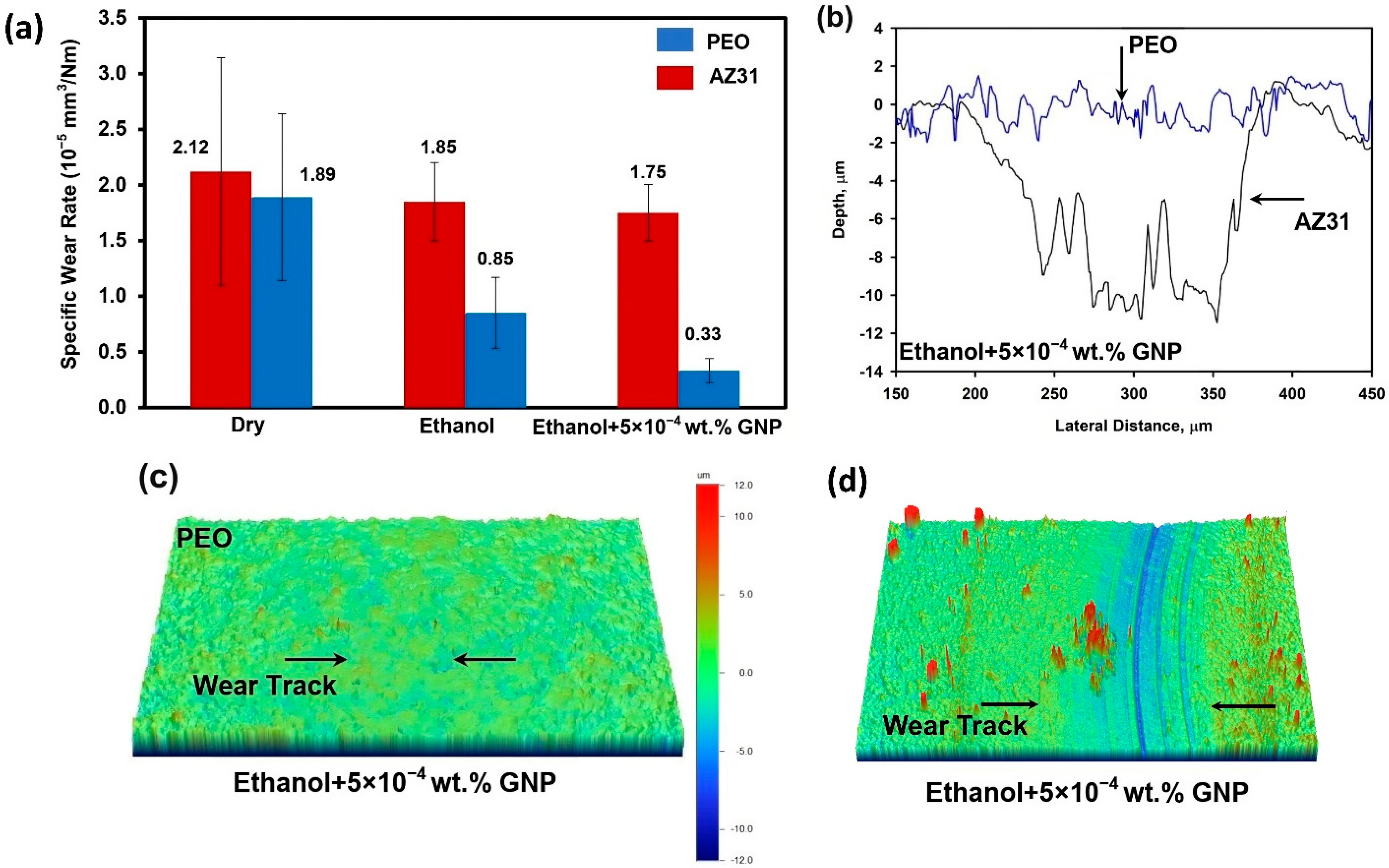
Figure 3a shows the wear rates of the uncoated AZ31 and the PEO-coated AZ31 tested under dry sliding conditions in ethanol alone and with GNPs. The wear rate of the uncoated AZ31 after dry sliding was measured at 2.12 × 10⁻⁵ mm3/Nm, which decreased to 1.85 × 10⁻⁵ mm3/Nm in ethanol. The lowest wear rate was observed in ethanol with GNPs, measuring 1.75 × 10⁻⁵ mm3/Nm. The PEO-coated AZ31 showed the lowest wear rate of 0.33 × 10⁻⁵ mm3/Nm when tested in ethanol with GNPs, compared to 1.89 × 10⁻⁵ mm3/Nm in dry sliding and 0.85 × 10⁻⁵ mm3/Nm in ethanol.
The effectiveness of the PEO-coating process was further demonstrated using 2D profiles of the worn surfaces, which provided both a visual representation and a quantification of the low wear rates observed for the PEO-coated AZ31 in ethanol with GNPs, as shown in Figure 3b. The maximum worn surface depth for the uncoated AZ31 was 12 µm in this typical section. When compared, the worn surface depth for the PEO-coated AZ31 was just 2 µm, signifying a notably lower wear rate for the coated specimen. Additionally, representative 3D surface profiles of the worn surface that were generated on the uncoated and PEO-coated AZ31 are shown in Figure 3c,d. The surface damage on the PEO-coated AZ31 was so minimal that it was challenging to discern, providing further evidence of the high wear resistance offered by the PEO coating.
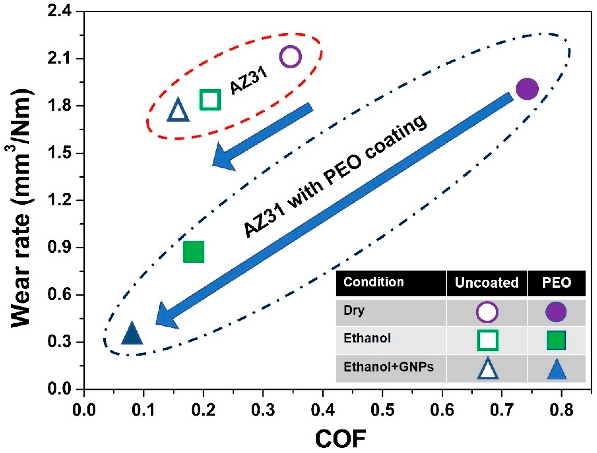
The observations of this section are gathered in Figure 4 as a “Wear Rate vs. COF” diagram. This figure clearly illustrates the effect of ethanol on reducing both the COF and the wear rate of the PEO-coated AZ31. In particular, the lowest values of the COF and the wear rate were achieved when the tests were conducted with ethanol-containing GNPs.

3.2. Worn Surfaces and Transfer Layer Formed during Testing in Ethanol and GNP- Added Ethanol

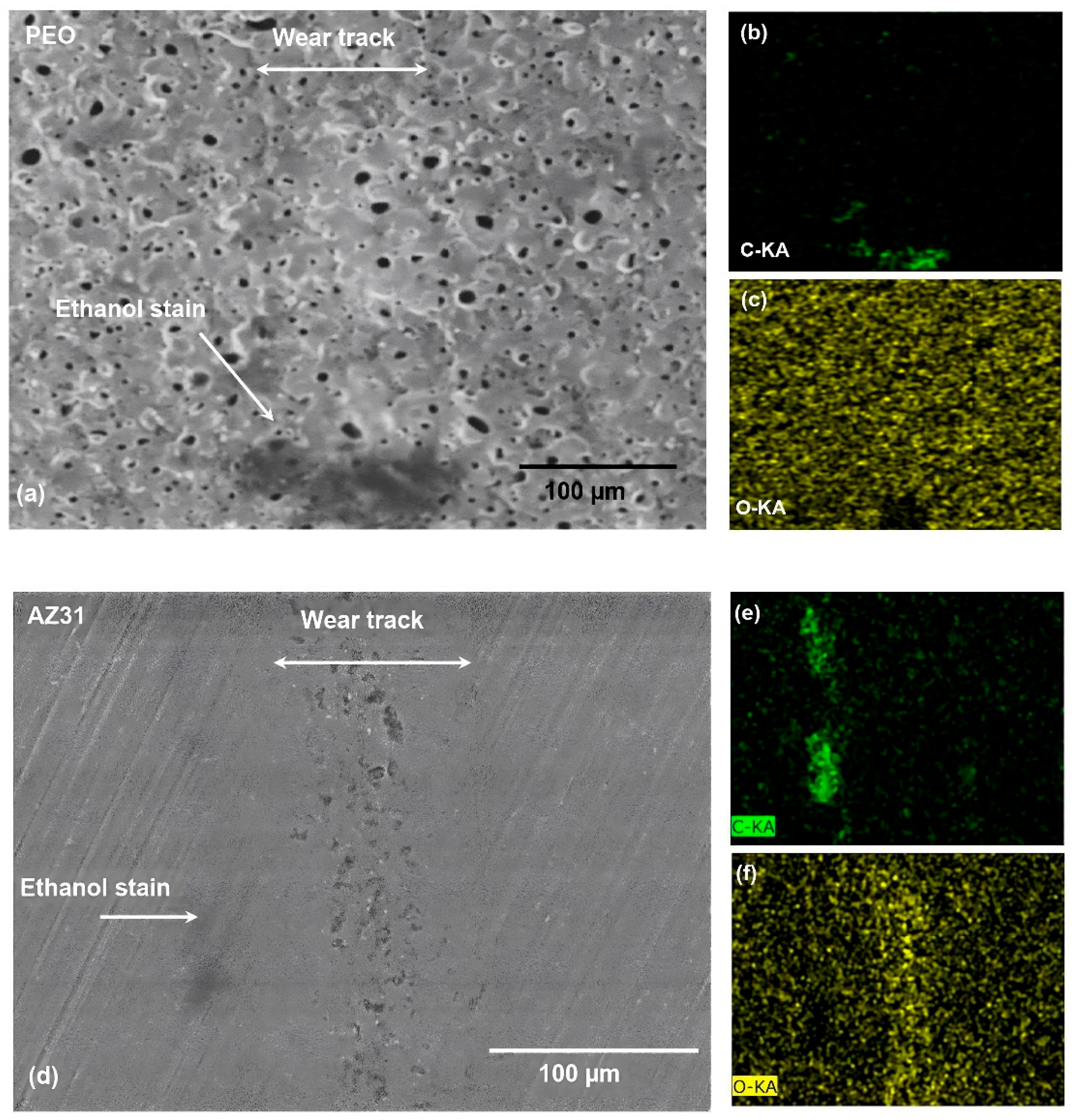
SEM analysis was conducted to examine the surface damage from wear developed on the PEO-coated AZ31 samples during sliding tests conducted in ethanol. The morphology of the worn surface generated on the PEO-coated AZ31 displayed no distinct differences from the surrounding regions, as evidenced by the secondary electron (SE) image presented in Figure 5a. The distinctive surface features of PEO coatings were still evident on the worn surface, aligning with the findings shown in the 3D profilometer in Figure 3c,d. The EDS mapping shown in Figure 5b shows that some areas on the worn surface appear as darker stains, possibly due to the reaction between Mg and ethanol. Figure 5c, the mapping of O proved that the worn surface was intact, and there was no sign of any detachment of the coating. The distribution of O was uniform along the worn surfaces.
An SEM analysis of the wear damage inflicted on the uncoated AZ31 subjected to sliding contact with steel in ethanol revealed evidence of local detachments, which were likely formed during material transfer to the counterface (Figure 5d). Carbon-rich stain marks were noticeable at the periphery of the wear region (Figure 5e). The majority of oxidation took place along the wear area, as depicted in Figure 5f.
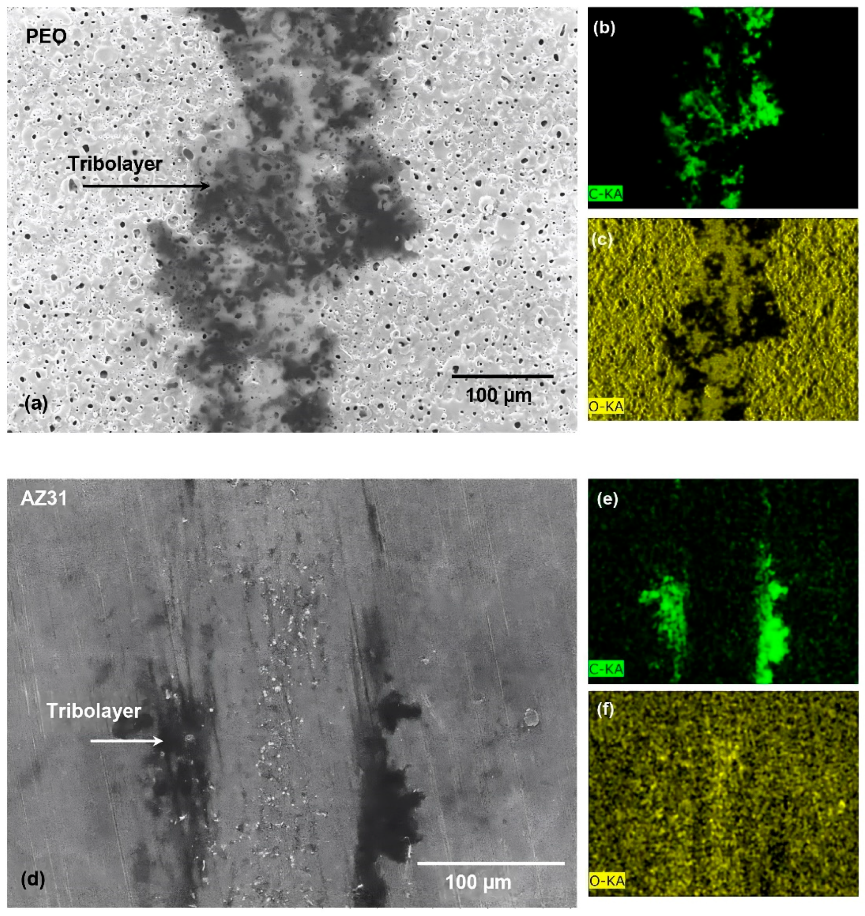
In the BSE image presented in Figure 6a, the worn surface of the PEO-coated AZ31, subjected to testing against the AISI 52100 steel ball in ethanol with GNPs, revealed distinct darker patches of C and O on the worn surface (Figure 6b,c). This observation suggests the creation of a tribolayer enriched with GNPs, which was formed almost uniformly along the sliding surface.
The worn surfaces of the uncoated AZ31 tested against 52100 steel balls in ethanol with GNPs were also examined. As shown in Figure 6d, the formation of tribolayers containing GNPs was discernible on the worn surface of the uncoated AZ31. However, this tribolayer exhibited non-uniformity. Compositional EDS mapping of C and O (Figure 6e,f) indicated that the GNP-containing layers were predominantly situated at the edges of the worn surface rather than being evenly distributed within the worn surface. Importantly, no indications of iron (Fe) transfer from the counterfaces were identified within the worn surfaces.
Results of the micro-Raman analyses performed on the pristine GNPs and the tribolayer generated on the PEO coating after sliding tests conducted in GNP-incorporated ethanol are shown in Figure 7. The peak positions of the D, G, 2D, and 2D’ peaks on the Raman spectra of the pristine GNPs were identified as 1346 cm−1, 1573 cm−1, 2705 cm−1, and 3233 cm−1, respectively [39]. The identification of peak positions for D, G, 2D, and 2D’ at 1326 cm−1, 1563 cm−1, 2700 cm−1, and 3223 cm−1, respectively, on the Raman spectra of the tribolayer provided confirmation that the carbon-rich tribolayers depicted in the SEM images (Figure 6a) were indeed composed of GNPs. Notably, it is important to observe that the D peak within the Raman spectra derived from the tribolayers displayed a more pronounced intensity compared to that of the pristine graphene. This heightened intensity of the D peak in the Raman spectra is often linked to structural irregularities like vacancies, edges, and grain boundaries. Additionally, the (D  +  G) peak appeared at ~ 2935 cm−1 in the Raman spectra of the tribolayer. As a result of the significant intensity of the D peak and the appearance of the (D + G) peak, there is evidence of the development of defects within the tribolayers [41].
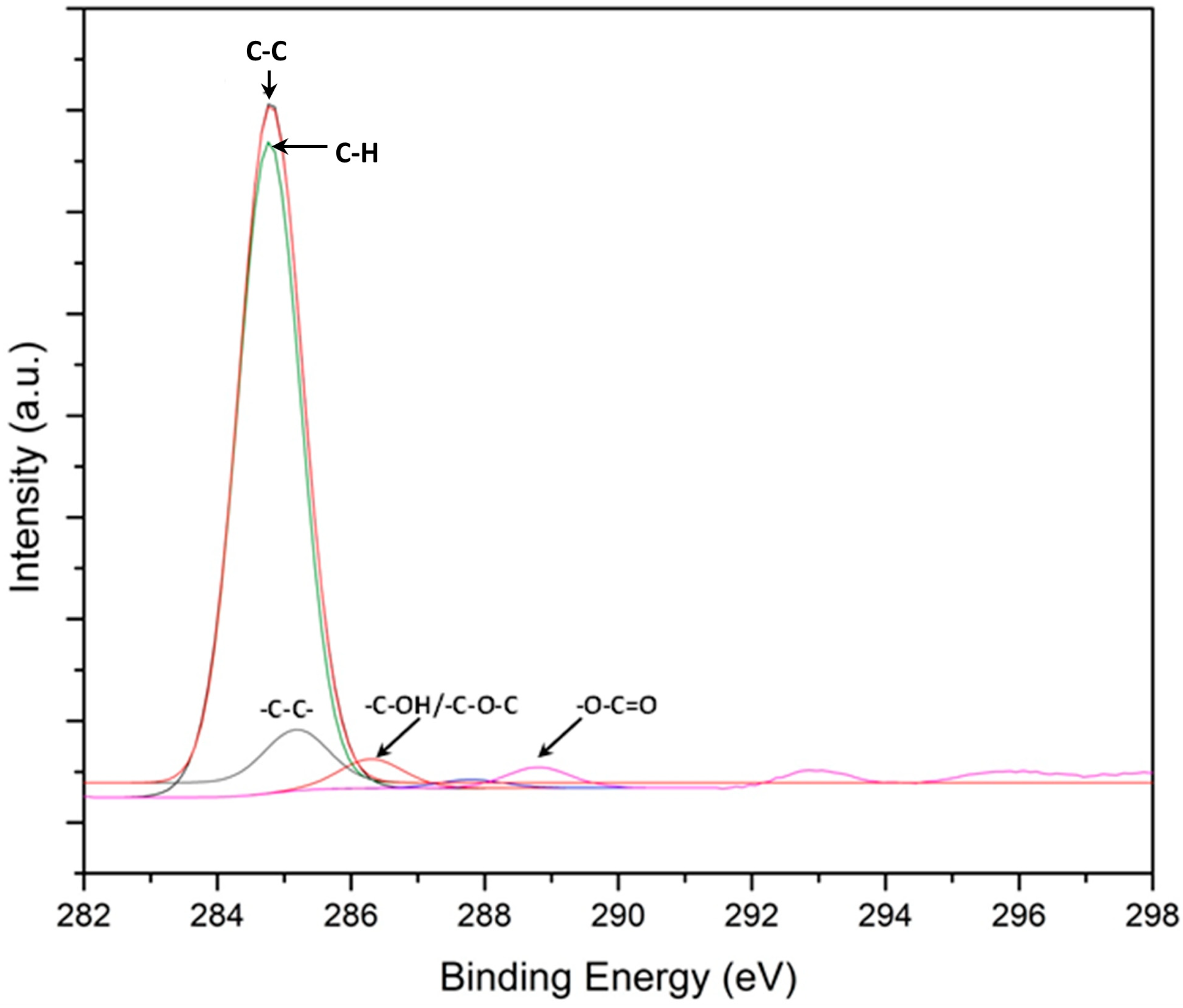
XPS analysis of the tribolayers, resulting from the sliding interaction between the PEO-coated AZ31 and the AISI 52100 steel in an ethanol environment enriched with GNPs, is depicted in Figure 8. The C1s peaks, detailed in the XPS spectrum in Figure 7, manifest at binding energies of 284.76 eV for C–C/–C–H, 286.36 eV for –C–OH/–C–O–C, and 288.86 eV for –O–C = O. These peaks are indicative of chemical alterations from the expected graphitic structure due to the tribological stress and interaction with ethanol, suggesting the presence of defects in the tribolayer. Such alterations are evidenced by the introduction of oxygen-containing groups and the disruption of the sp2 hybridized carbon network, which are not typical for an unreacted graphitic lattice. Prior studies [42,43,44] support these findings, proposing that these functional groups can form as a result of mechanical and chemical processes during sliding. Complementary Raman analysis, presented in Figure 6, confirms the structural disorder associated with these chemical states, revealing the passivation of defects through the incorporation of –H and –OH moieties. These groups are presumably derived from the dissociation of ethanol, signifying a dynamic interplay of mechanical and chemical transformations within the tribolayer during the wear process.

3.3. Wear and Surface Characterization of Counterface Balls Used in Sliding Wear Tests

Table 1 provides an overview of the volume losses experienced by the 52100 steel counterface in various conditions when sliding against the uncoated AZ31 and the PEO-coated AZ31. These tests were conducted in three different environments: dry, ethanol, and ethanol-containing GNPs. The estimation of counterface wear utilized a spherical cap volume loss model, accounting for the diameter of the worn surface formed on the counterface material.
Consistent with expectations, the highest volume losses were observed during dry sliding, followed by sliding in an ethanol environment. Notably, tests carried out in ethanol with GNPs demonstrated a distinct advantage. These conditions facilitated the development of a tribolayer enriched with graphene on the contact surface of the counterfaces, leading to a reduction in counterface damage. For the uncoated AZ31, the recorded volume loss from the counterface was 22.34 × 10⁻⁴ mm3. In contrast, the PEO-coated AZ31 exhibited a 50% reduction in volume loss (11.02 × 10⁻⁴ mm3). These results underscore the notable effectiveness of the PEO coating in mitigating counterface wear. Furthermore, the incorporation of GNPs in ethanol as a lubricant additive provided an additional advantage, enhancing the overall tribological performance.
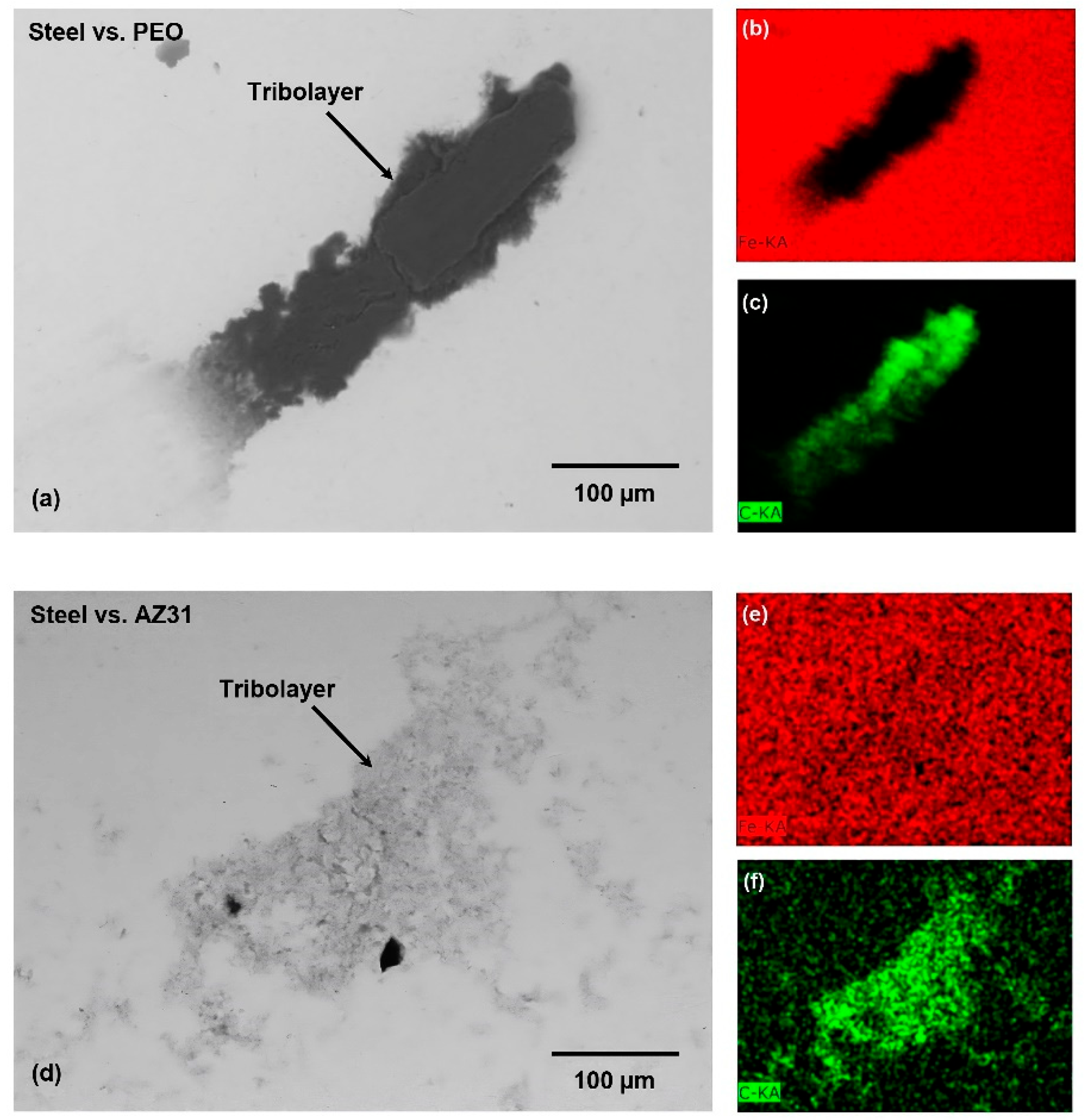
The contact surfaces of the counterface 52100 balls used to test the PEO-coated AZ31 and the uncoated AZ31 were examined using SEM and EDS. Figure 9a displays the tribolayer that developed on the upper surface of the steel counterface during sliding in ethanol containing GNPs. The EDS maps for Fe (Figure 9b) and C (Figure 9c) provided evidence that the resulting tribolayer was predominantly composed of C. Similarly, a tribolayer rich in C was formed on the upper surface of the counterface steel ball employed in the tests involving the uncoated AZ31 in the GNP-incorporated ethanol solution (Figure 9d). This was confirmed through the EDS mapping of Fe and C (Figure 9e,f). Notably, the carbon-rich layer observed on the steel surface (Figure 9e) displayed similarities to the steel balls utilized for the testing of the PEO coating (Figure 9b,c). This carbon-rich tribolayer on the counterface is likely a consequence of the presence of GNPs, which can form a thin layer on the counterface surface during the sliding process. The XPS analysis indicated the presence of C–C/–C–H and –C–OH/–C–O–C bonds on the surface, which implies that the H and –OH species derived from the ethanol dissociation have acted to passivate the C–C interactions between the graphene layers of the GNPs and the metal surfaces. This suggests that the passivation of the C–C interactions likely contributes to the mechanism responsible for the observed low COF in the PEO coating. This passivation of graphene within the tribolayer can reduce friction and wear between the sliding surfaces by inhibiting the adhesive transfer of counterface materials and decreasing surface energy. This phenomenon occurs because passivation creates a barrier layer that effectively separates the surfaces in contact, thereby reducing the shear strength and contact area. Moreover, passivation can stabilize the tribolayer, preventing its removal and leading to reduced wear rates and COF values.

4. Discussion

To initiate the discussion, it is pertinent to analyze the COF curves generated during the dry sliding of the uncoated AZ31 and the PEO-coated AZ31. While the uncoated AZ31 demonstrated a lower COF than the PEO-coated AZ31, it also displayed significant fluctuations. These COF fluctuations correspond with the reciprocating transfer of detached material fragments between the worn surface of the uncoated AZ31 and the counterface during sliding contact. This phenomenon resulted in the oxidation of the worn surfaces and the transferred material.
A reduction in the COF value of the Mg alloys in aqueous media (i.e., water, simulated body fluid) compared to dry sliding contact was reported in the literature [43,45,46]. The reduction in the COF was linked to the generation of Mg(OH)2 on the worn surfaces due to the tribo-chemical reactions of Mg and MgO with the dissociated species in the aqueous media (such as -H and -OH) according to the following reactions [43]:
2Mg + O2 → 2MgO
Mg + 2H2O → Mg(OH)2 + H2 ↑
MgO + H2O → Mg(OH)2
While no specific tribo-chemical reaction has been reported for the sliding contact of Mg alloys in ethanol, the lubricating effect of alcohols on various metallic surfaces during sliding contact has been associated with the formation of metal ethoxides [44,47,48]. The formation of magnesium ethoxide (Mg(C2H5O)2) under static conditions is represented by the following equation [44]:
MgO + 2C2H5OH → Mg(C2H5O)2 + H2O
This reaction entails the displacement of water (H2O) from the surface of MgO by ethoxide ions (C2H5O), creating Mg(C2H5O)2 and H2O. Typically, this reaction occurs under static conditions, where MgO and ethanol remain in contact for an extended duration. However, sliding contact would expedite the amalgamation and tribo-chemical interplay between MgO and ethanol.
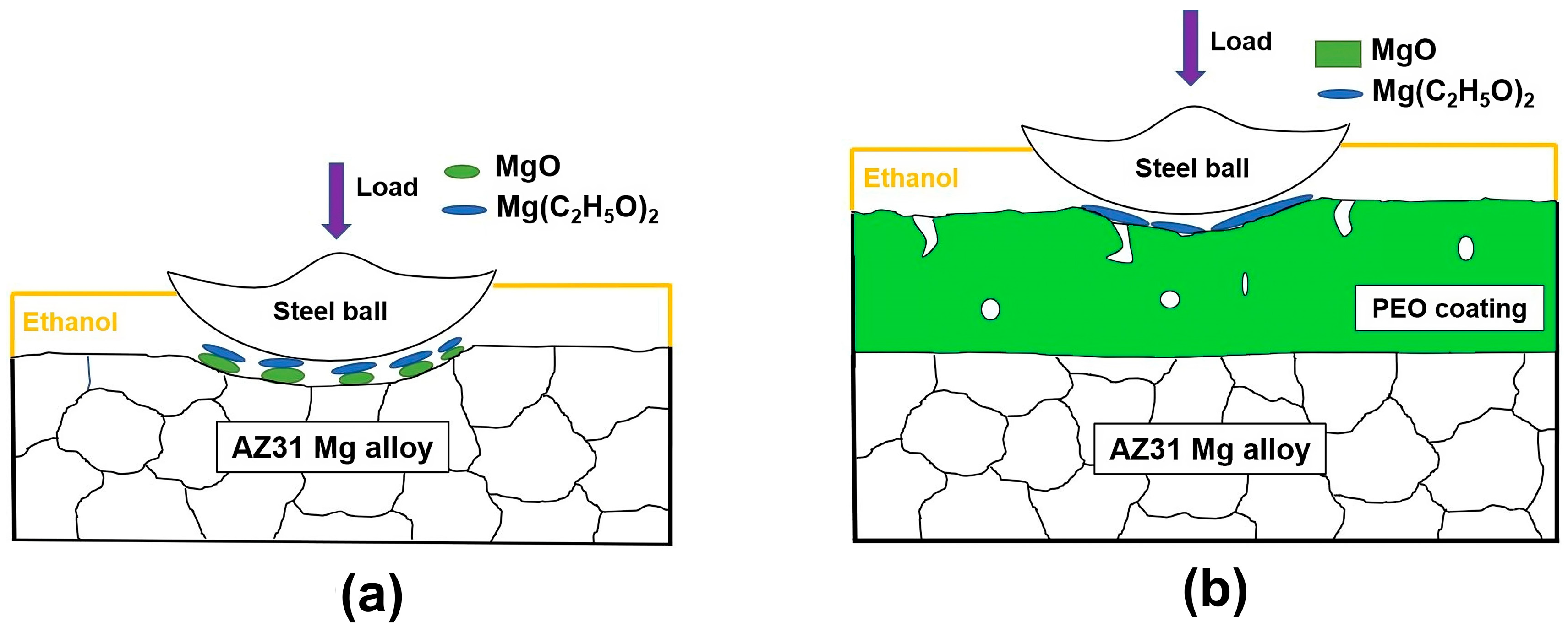
Figure 10a,b illustrate schematic models that depict the wear mechanisms of the uncoated AZ31 and the PEO-coated AZ31, respectively, when exposed to ethanol. For the uncoated AZ31 alloy, the expected formation of Mg(C2H5O)2 could follow the sequence of reactions 1 and 4. This is tentatively linked to the fluctuating friction curve of the untreated AZ31 in ethanol, a contrast to the smoother curve of the PEO-coated AZ31 (as shown in Figure 1 and Figure 2). The MgO present in the PEO coating may facilitate the formation of an ethoxide layer, potentially contributing to the observed reduction in the COF and the wear rate (Figure 4). It should be noted, however, that the direct observation of Mg(C2H5O)2 formation due to tribo-chemical reactions in the presence of ethanol was not achieved in this study. Nevertheless, the known lubricating effects of alcohols on metallic surfaces suggest that similar reactions could be at play, influencing tribological behavior [14,15]. For example, the existence of O along the wear track of the uncoated AZ31 tested in ethanol (Figure 5f) may imply the formation of magnesium ethoxide. To confirm these proposed mechanisms, future work should include in situ spectroscopic analysis during sliding to elucidate the chemistry–tribology interplay within the tribolayer.
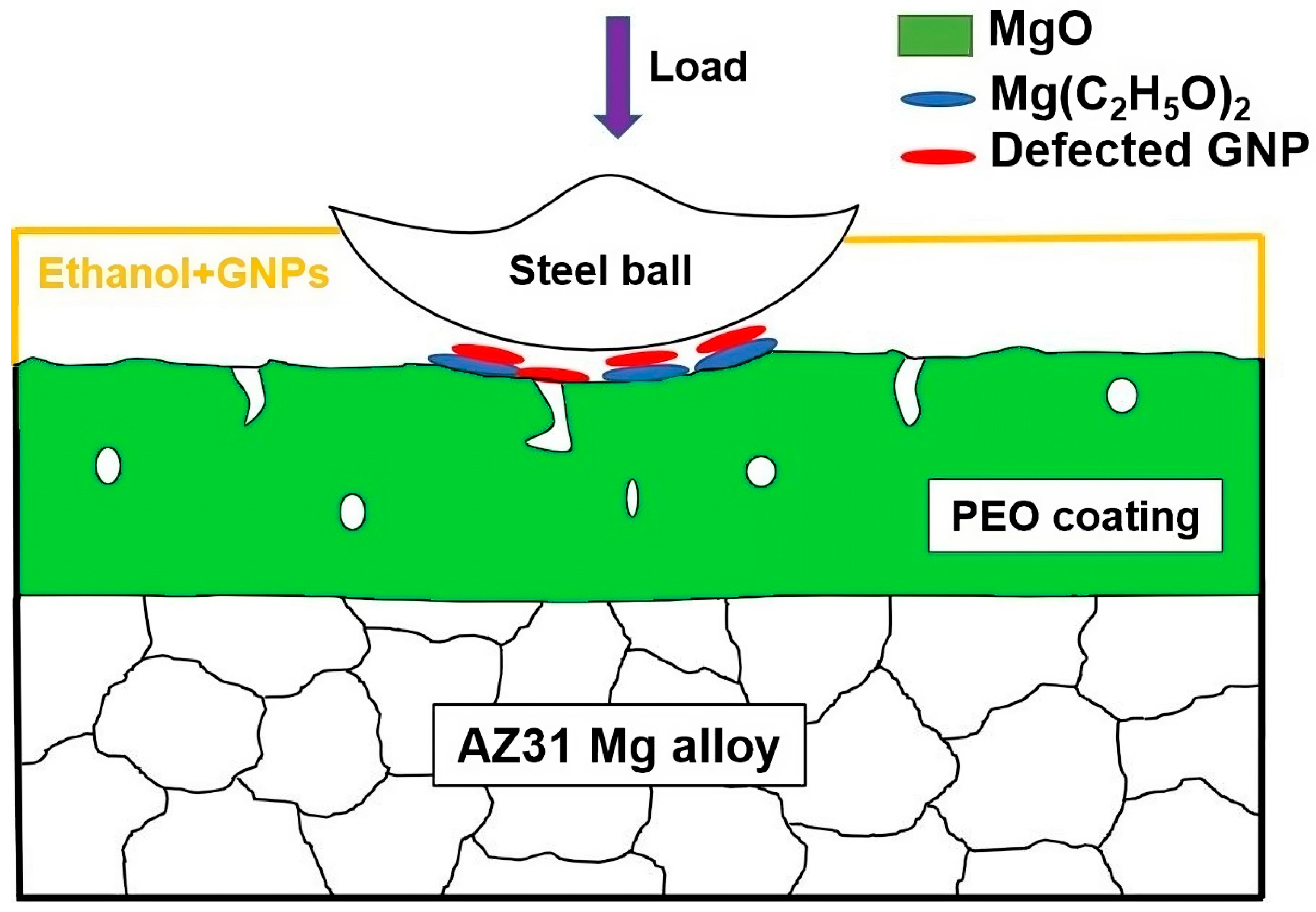
A model illustrating the underlying mechanism behind the enhanced tribological performance of the PEO-coated AZ31 in GNP-incorporated ethanol is presented in Figure 11. The addition of GNPs to the ethanol lubricant significantly reduced the COF and the wear rate for AZ31; this improvement was observed in both the uncoated and PEO-coated variants, although the mechanisms contributing to these reductions differ. Notably, the lowest COF and wear rate were recorded for the PEO-coated AZ31. In this case, the damage to the graphene in the tribolayer, evidenced by the decreased D to G band intensity ratio in Raman spectroscopy, results in fractured edges and structural vacancies [28,49]. These defects are believed to enhance the graphene’s ability to passivate [41,50,51], facilitating the formation of C–C/–C–H and –C–OH/–C–O–C bonds on the surface, as identified in Figure 8. This passivation is postulated to prevent further tribolayer degradation, improve its stability, and thus contribute to the reduction in friction and wear for the PEO-coated surfaces.

5. Conclusions

This study investigated the tribological behaviour of AZ31 Mg alloys with and without a PEO coating under sliding contact with steel in anhydrous ethanol and examined the effects of the addition of graphene nanoplatelets (GNPs). The main findings demonstrated that the incorporation of GNPs in ethanol effectively decreased the COF of the PEO-coated AZ31 compared to the uncoated AZ31. Furthermore, sliding tests with GNP-incorporated ethanol reduced the wear of the PEO-coated surfaces, creating a more favourable sliding environment compared to the uncoated AZ31 surfaces. This resulted from differences in tribolayer formation between the PEO-coated AZ31 and the uncoated AZ31 alloys.
Based on the results of this study, the following conclusions can be drawn:
  • The PEO-coated AZ31 surfaces maintained a steady-state COF of 0.18 in ethanol, a value lower than that observed in dry sliding (0.74), and closely matched that of uncoated AZ31.
  • Tests conducted in ethanol with the addition of 5 × 10⁻⁴ wt.% GNPs significantly decreased the COF to 0.07 and the wear rate of PEO-coated AZ31 from 18.36 × 10⁻⁴ mm3 (when tested in ethanol) to 11.02 × 10⁻⁴ mm3, demonstrating superior performance compared to the uncoated AZ31.
  • XPS, Raman spectroscopy, and SEM analyses revealed the formation of a stable tribolayer on the PEO-coated AZ31 and the steel counterface during sliding in ethanol with dispersed GNPs.
  • GNPs in ethanol were less effective as a lubricant for the uncoated AZ31. The enhanced performance of the PEO-coated AZ31 in ethanol with GNPs was due to a combination of the formation of graphene-incorporated tribolayers and their chemical interactions within the ethanol environment.

Author Contributions

S.B.: Investigation, Methodology, Writing—Original Draft; F.M.: Investigation, Methodology, Writing—Reviewing and Editing; S.S.: Investigation; H.C.: Supervision, Conceptualization, Writing—Reviewing and Editing; A.T.A.: Supervision, Conceptualization, Writing—Reviewing and Editing. All authors have read and agreed to the published version of the manuscript.

Funding

This paper has been financially supported by The Natural Sciences and Engineering Research Council of Canada (NSERC) Discovery Grant No. 06340-2018.

Data Availability Statement

Data available on request from the authors.

Conflicts of Interest

There are no known competing financial interest or personal relationship between the authors that may affect the work reported in this article.

References

  1. Pesode, P.; Barve, S. Surface Modification of Titanium and Titanium Alloy by Plasma Electrolytic Oxidation Process for Biomedical Applications: A Review. Mater. Today Proc. 2021, 46, 594–602. [Google Scholar] [CrossRef]
  2. Clyne, T.W.; Troughton, S.C. A Review of Recent Work on Discharge Characteristics during Plasma Electrolytic Oxidation of Various Metals. Int. Mater. Rev. 2019, 64, 127–162. [Google Scholar] [CrossRef]
  3. Yao, W.; Wu, L.; Wang, J.; Jiang, B.; Zhang, D.; Serdechnova, M.; Shulha, T.; Blawert, C.; Zheludkevich, M.L.; Pan, F. Micro-arc Oxidation of Magnesium Alloys: A Review. J. Mater. Sci. Technol. 2022, 118, 158–180. [Google Scholar] [CrossRef]
  4. Zhang, J.; Dai, W.; Wang, X.; Wang, Y.; Yue, H.; Li, Q.; Yang, X.; Guo, C.; Li, C. Micro-Arc Oxidation of Al Alloys: Mechanism, Microstructure, Surface Properties, and Fatigue Damage Behavior. J. Mater. Res. Technol. 2023, 23, 4307–4333. [Google Scholar] [CrossRef]
  5. Schwartz, A.; Kossenko, A.; Zinigrad, M.; Danchuk, V.; Sobolev, A. Cleaning Strategies of Synthesized Bioactive Coatings by PEO on Ti-6Al-4V Alloys of Organic Contaminations. Materials 2023, 16, 4624. [Google Scholar] [CrossRef]
  6. Liang, J.; Guo, B.; Tian, J.; Liu, H.; Zhou, J.; Xu, T. Effect of Potassium Fluoride in Electrolytic Solution on the Structure and Properties of Microarc Oxidation Coatings on Magnesium Alloy. Appl. Surf. Sci. 2005, 252, 345–351. [Google Scholar] [CrossRef]
  7. Liang, J.; Wang, P.; Hu, L.; Hao, J. Tribological Properties of Duplex MAO/DLC Coatings on Magnesium Alloy Using Combined Microarc Oxidation and Filtered Cathodic Arc Deposition. Mater. Sci. Eng. A 2007, 454–455, 164–169. [Google Scholar] [CrossRef]
  8. Fattah-alhosseini, A.; Chaharmahali, R. Enhancing Corrosion and Wear Performance of PEO Coatings on Mg Alloys Using Graphene and Graphene Oxide Additions: A Review. FlatChem 2021, 27, 100241. [Google Scholar] [CrossRef]
  9. Chen, F.; Zhang, Y.; Zhang, Y. Effect of Graphene on Micro-Structure and Properties of MAO Coating Prepared on Mg-Li Alloy. Int. J. Electrochem. Sci. 2017, 12, 6081–6091. [Google Scholar] [CrossRef]
  10. Nasiri Vatan, H.; Adabi, M. Investigation of Tribological Behavior of Ceramic–Graphene Composite Coating Produced by Plasma Electrolytic Oxidation. Trans. Indian Inst. Met. 2018, 71, 1643–1652. [Google Scholar] [CrossRef]
  11. Bhowmick, S.; Muhaffel, F.; Sun, G.; Cimenoglu, H.; Alpas, A.T. Role of Counterfaces with DLC and N-Based Coatings on Frictional Behaviour of AZ31 Magnesium Alloy Subjected to Plasma Electrolytic Oxidation (PEO) Process. Surf. Coatings Technol. 2020, 397, 125997. [Google Scholar] [CrossRef]
  12. Bhowmick, S.; Muhaffel, F.; Eskandari, B.; Cimenoglu, H.; Alpas, A.T. Low Friction and High Wear Resistance of Plasma Electrolytic Oxidation (PEO)-Coated AZ31 Mg Alloy Sliding against Hydrogenated DLC (a-C-H) at Elevated Temperatures. Coatings 2022, 12, 607. [Google Scholar] [CrossRef]
  13. Tokgoz, S.; Traoré, F. Understanding E10 Markets in the U.S.: Evidence from Spatial Data. Econ. Anal. Policy 2023, 78, 1267–1281. [Google Scholar] [CrossRef]
  14. Kubo, T.; Nanao, H.; Mori, S.; Enomoto, Y.; Nie, H.; Nomura, H. Chemical Analysis of Boundary Lubrication Film Formed on Metal Nitride Coatings with Ethanol by Means of TOF-SIMS. Wear 2010, 268, 1225–1229. [Google Scholar] [CrossRef]
  15. Bandeira, A.L.; Trentin, R.; Aguzzoli, C.; Maia da Costa, M.E.H.; Michels, A.F.; Baumvol, I.J.R.; Farias, M.C.M.; Figueroa, C.A. Sliding Wear and Friction Behavior of CrN-Coating in Ethanol and Oil-Ethanol Mixture. Wear 2013, 301, 786–794. [Google Scholar] [CrossRef]
  16. Kim, K.S.; Lee, H.J.; Lee, C.; Lee, S.K.; Jang, H.; Ahn, J.H.; Kim, J.H.; Lee, H.J. Chemical Vapor Deposition-Grown Graphene: The Thinnest Solid Lubricant. ACS Nano 2011, 5, 5107–5114. [Google Scholar] [CrossRef] [PubMed]
  17. Eswaraiah, V.; Sankaranarayanan, V.; Ramaprabhu, S. Graphene-Based Engine Oil Nanofluids for Tribological Applications. ACS Appl. Mater. Interfaces 2011, 3, 4221–4227. [Google Scholar] [CrossRef]
  18. Huang, J.; Tan, J.; Fang, H.; Gong, F.; Wang, J. Tribological and Wear Performances of Graphene-Oil Nanofluid under Industrial High-Speed Rotation. Tribol. Int. 2019, 135, 112–120. [Google Scholar] [CrossRef]
  19. Gan, C.; Liang, T.; Chen, D.; Li, W.; Fan, X.; Tang, G.; Lin, B.; Zhu, M. Phosphonium-Organophosphate Modified Graphene Gel towards Lubrication Applications. Tribol. Int. 2020, 145, 106180. [Google Scholar] [CrossRef]
  20. Kong, S.; Wang, J.; Hu, W.; Li, J. Effects of Thickness and Particle Size on Tribological Properties of Graphene as Lubricant Additive. Tribol. Lett. 2020, 68, 112. [Google Scholar] [CrossRef]
  21. Ren, J.; Gong, K.; Zhao, G.; Lou, W.; Wu, X.; Wang, X. Investigation of the Tribological Performances of Graphene and WS2 Nanosheets as Additives for Perfluoroalkylpolyethers Under Simulated Space Environment. Tribol. Lett. 2021, 69, 45. [Google Scholar] [CrossRef]
  22. Nasser, K.I.; Liñeira del Río, J.M.; Mariño, F.; López, E.R.; Fernández, J. Double Hybrid Lubricant Additives Consisting of a Phosphonium Ionic Liquid and Graphene Nanoplatelets/Hexagonal Boron Nitride Nanoparticles. Tribol. Int. 2021, 163, 107189. [Google Scholar] [CrossRef]
  23. Bertolini, R.; Ghiotti, A.; Bruschi, S. Graphene Nanoplatelets as Additives to MQL for Improving Tool Life in Machining Inconel 718 Alloy. Wear 2021, 476, 203656. [Google Scholar] [CrossRef]
  24. Zhang, D.; Du, X.; Bai, A.; Wang, L. The Synergistic Effect of MAO-Treated and PAO–Graphene Oil on Tribological Properties of Ti6Al4V Alloys. Wear 2022, 510–511, 204494. [Google Scholar] [CrossRef]
  25. Wang, L.; Gong, P.; Li, W.; Luo, T.; Cao, B. Mono-Dispersed Ag/Graphene Nanocomposite as Lubricant Additive to Reduce Friction and Wear. Tribol. Int. 2020, 146, 106228. [Google Scholar] [CrossRef]
  26. Liu, Y.; Mateti, S.; Li, C.; Liu, X.; Glushenkov, A.M.; Liu, D.; Li, L.H.; Fabijanic, D.; Chen, Y. Synthesis of Composite Nanosheets of Graphene and Boron Nitride and Their Lubrication Application in Oil. Adv. Eng. Mater. 2018, 20, 1700488. [Google Scholar] [CrossRef]
  27. Sikdar, S.; Rahman, M.H.; Ralls, A.M.; Menezes, P.L. Enhancement in Tribological Performance of Plastic Oil by Solid Lubricant Additives. Lubr. Sci. 2023, 35, 420–437. [Google Scholar] [CrossRef]
  28. Berman, D.; Erdemir, A.; Sumant, A.V. Graphene: A New Emerging Lubricant. Mater. Today 2014, 17, 31–42. [Google Scholar] [CrossRef]
  29. Fan, X.; Xia, Y.; Wang, L.; Li, W. Multilayer Graphene as a Lubricating Additive in Bentone Grease. Tribol. Lett. 2014, 55, 455–464. [Google Scholar] [CrossRef]
  30. Mungse, H.P.; Kumar, N.; Khatri, O.P. Synthesis, Dispersion and Lubrication Potential of Basal Plane Functionalized Alkylated Graphene Nanosheets. RSC Adv. 2015, 5, 25565–25571. [Google Scholar] [CrossRef]
  31. Sanes, J.; Avilés, M.D.; Saurín, N.; Espinosa, T.; Carrión, F.J.; Bermúdez, M.D. Synergy between Graphene and Ionic Liquid Lubricant Additives. Tribol. Int. 2017, 116, 371–382. [Google Scholar] [CrossRef]
  32. Bordignon, R.; Salvaro, D.; Binder, C.; Klein, A.N.; Drago, V.; de Mello, J.D.B. Tribological Behaviour of Plasma-Functionalized Graphene as Low-Viscosity Oil Additive. Tribol. Lett. 2018, 66, 114. [Google Scholar] [CrossRef]
  33. Ali, M.K.A.; Xianjun, H.; Abdelkareem, M.A.A.; Gulzar, M.; Elsheikh, A.H. Novel Approach of the Graphene Nanolubricant for Energy Saving via Anti-Friction/Wear in Automobile Engines. Tribol. Int. 2018, 124, 209–229. [Google Scholar] [CrossRef]
  34. Paul, G.; Shit, S.; Hirani, H.; Kuila, T.; Murmu, N.C. Tribological Behavior of Dodecylamine Functionalized Graphene Nanosheets Dispersed Engine Oil Nanolubricants. Tribol. Int. 2019, 131, 605–619. [Google Scholar] [CrossRef]
  35. Kogovšek, J.; Kalin, M. Lubrication Performance of Graphene-Containing Oil on Steel and DLC-Coated Surfaces. Tribol. Int. 2019, 138, 59–67. [Google Scholar] [CrossRef]
  36. Elomaa, O.; Singh, V.K.; Iyer, A.; Hakala, T.J.; Koskinen, J. Graphene Oxide in Water Lubrication on Diamond-like Carbon vs. Stainless Steel High-Load Contacts. Diam. Relat. Mater. 2015, 52, 43–48. [Google Scholar] [CrossRef]
  37. Wu, L.; Zhong, Y.; Yuan, H.; Liang, H.; Wang, F.; Gu, L. Ultra-Dispersive Sulfonated Graphene as Water-Based Lubricant Additives for Enhancing Tribological Performance. Tribol. Int. 2022, 174, 107759. [Google Scholar] [CrossRef]
  38. Berman, D.; Erdemir, A.; Sumant, A.V. Few Layer Graphene to Reduce Wear and Friction on Sliding Steel Surfaces. Carbon N. Y. 2013, 54, 454–459. [Google Scholar] [CrossRef]
  39. Bhowmick, S.; Yang, Z.; Banerji, A.; Alpas, A.T. Effect of Graphene Nanoplates Dispersed in Ethanol on Frictional Behaviour of Tool Steel Running Against Uncoated and DLC-Coated Tool Steel. Tribol. Lett. 2019, 67, 32. [Google Scholar] [CrossRef]
  40. Bhushan, B. Principles and Applications of Tribology, 2nd ed.; John Wiley & Sons, Ltd.: Columbus, OH, USA, 2013; ISBN 3527305521. [Google Scholar]
  41. Bhowmick, S.; Banerji, A.; Alpas, A.T. Role of Humidity in Reducing Sliding Friction of Multilayered Graphene. Carbon N. Y. 2015, 87, 374–384. [Google Scholar] [CrossRef]
  42. Kim, B.I.; Lee, S.; Guenard, R.; Fernandez Torres, L.C.; Perry, S.S.; Frantz, P.; Didziulis, S.V. Chemical Modification of the Interfacial Frictional Properties of Vanadium Carbide through Ethanol Adsorption. Surf. Sci. 2001, 481, 185–197. [Google Scholar] [CrossRef]
  43. Zhu, T.; Yu, Y.; Shen, Y.; Xiong, Y. Wear Behavior of Extruded ZK60 Magnesium Alloy in Simulated Body Fluid with Different PH Values. Mater. Chem. Phys. 2021, 262, 124292. [Google Scholar] [CrossRef]
  44. Takezawa, N.; Hanamaki, C.; Kobayashi, H. The Mechanism of Dehydrogenation of Ethanol on Magnesium Oxide. J. Catal. 1975, 38, 101–109. [Google Scholar] [CrossRef]
  45. Liu, D.B.; Wu, B.; Wang, X.; Chen, M.F. Corrosion and Wear Behavior of an Mg–2Zn–0.2Mn Alloy in Simulated Body Fluid. Rare Met. 2015, 34, 553–559. [Google Scholar] [CrossRef]
  46. Dai, J.; Zhang, X.; Yin, Q.; Ni, S.; Ba, Z.; Wang, Z. Friction and Wear Behaviors of Biodegradable Mg-6Gd-0.5Zn-0.4Zr Alloy under Simulated Body Fluid Condition. J. Magnes. Alloys 2017, 5, 448–453. [Google Scholar] [CrossRef]
  47. Konicek, A.R.; Grierson, D.S.; Sumant, A.V.; Friedmann, T.A.; Sullivan, J.P.; Gilbert, P.U.P.A.; Sawyer, W.G.; Carpick, R.W. Influence of Surface Passivation on the Friction and Wear Behavior of Ultrananocrystalline Diamond and Tetrahedral Amorphous Carbon Thin Films. Phys. Rev. B Condens. Matter Mater. Phys. 2012, 85, 155448. [Google Scholar] [CrossRef]
  48. Barthel, A.J.; Al-Azizi, A.; Surdyka, N.D.; Kim, S.H. Effects of Gas or Vapor Adsorption on Adhesion, Friction, and Wear of Solid Interfaces. Langmuir 2014, 30, 2977–2992. [Google Scholar] [CrossRef]
  49. Dilks, A.; Kay, E. Plasma Polymerization of Ethylene and the Series of Fluoroethylenes: Plasma Effluent Mass Spectrometry and ESCA Studies. Macromolecules 1981, 14, 855–862. [Google Scholar] [CrossRef]
  50. Rietsch, J.C.; Brender, P.; Dentzer, J.; Gadiou, R.; Vidal, L.; Vix-Guterl, C. Evidence of Water Chemisorption during Graphite Friction under Moist Conditions. Carbon N. Y. 2013, 55, 90–97. [Google Scholar] [CrossRef]
  51. Egberts, P.; Han, G.H.; Liu, X.Z.; Johnson, A.T.C.; Carpick, R.W. Frictional Behavior of Atomically Thin Sheets: Hexagonal-Shaped Graphene Islands Grown on Copper by Chemical Vapor Deposition. ACS Nano 2014, 8, 5010–5021. [Google Scholar] [CrossRef]
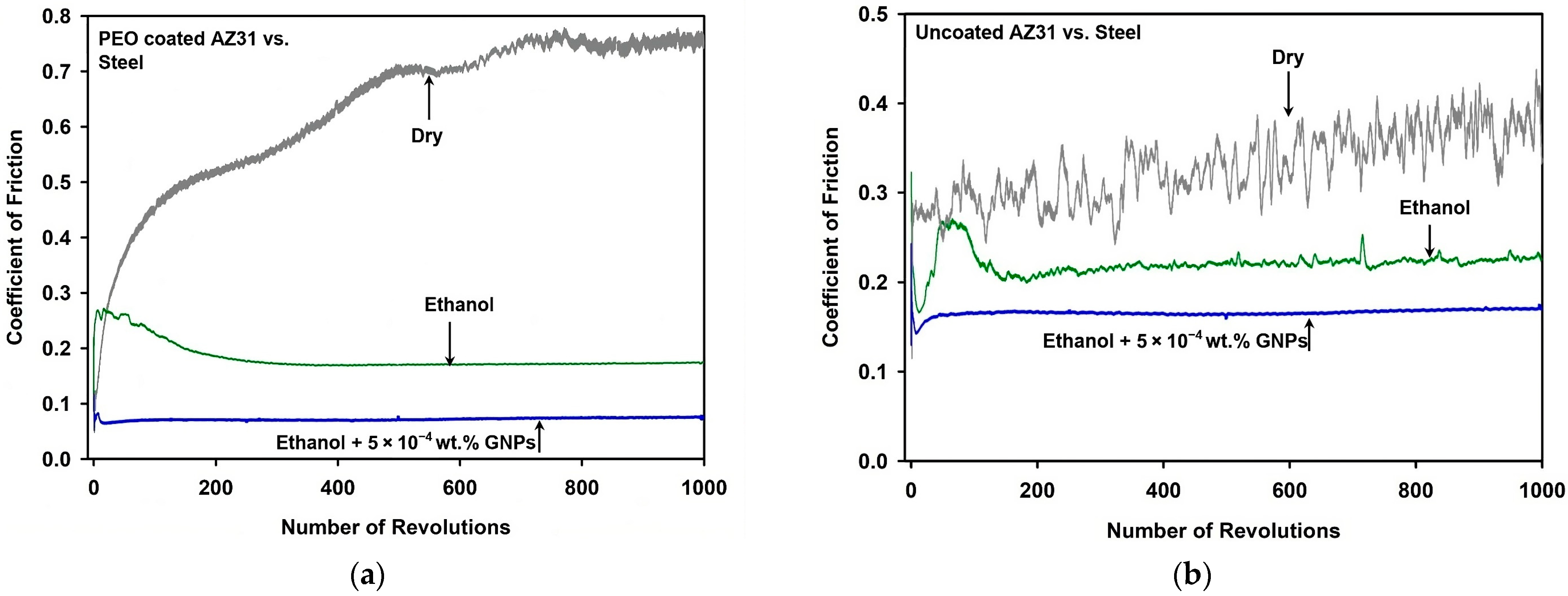
Figure 1. (a) COF variations with the number of revolutions when PEO-coated AZ31 was tested in dry, ethanol, and ethanol with 5  ×  10−4 wt.% GNPs conditions. (b) COF variations with the number of revolutions when the uncoated AZ31 was tested in dry, ethanol, and ethanol with 5  ×  10−4 wt.% GNPs conditions.
Lubricants 12 00009 g001
Figure 2. (a) Average running-in and (b) average steady-state COF values obtained from three tests when PEO-coated AZ31 and uncoated AZ31 were tested in dry, ethanol, and ethanol with 5 × 10⁻⁴ wt.% GNPs conditions.
Lubricants 12 00009 g002
Figure 3. (a) Comparison of wear rates of PEO-coated AZ31 and uncoated AZ31 in dry, ethanol, and ethanol with 5.0  ×  10−4 wt.% GNPs conditions. (b) Typical 2D profile of the wear track formed on PEO-coated AZ31 and uncoated AZ31 after sliding in ethanol with 5.0  ×  10−4 wt.% GNPs. (c) Typical 3D profile of the wear track formed on the surface of PEO-coated AZ31 after sliding in ethanol with 5.0  ×  10−4 wt.% GNPs. (d) Typical 3D profile of the wear track formed on the surface of uncoated AZ31 after sliding in ethanol with 5.0  ×  10−4 wt.% GNPs. The edges of the wear tracks were showed by black arrows.
Lubricants 12 00009 g003
Figure 4. Wear rate vs. COF diagram for PEO-coated AZ31 and uncoated AZ31 samples tested against steel in dry, ethanol, and ethanol with 5 × 10⁻⁴ wt.% GNPs conditions.
Lubricants 12 00009 g004
Figure 5. (a) SE image of the section of a wear track formed on PEO-coated AZ31 after sliding against steel in ethanol. The elemental EDS maps obtained from the entire area shown in (a) are for (b) C and (c) O. (d) SE image of the section of a wear track formed on the uncoated AZ31 after sliding against steel in ethanol. The elemental EDS maps taken from the entire region shown in (d) are for (e) C and (f) O.
Lubricants 12 00009 g005
Figure 6. (a) SE image of the section of a wear track formed on PEO-coated AZ31 after sliding against steel in ethanol with 5 × 10⁻⁴ wt.% GNPs. The elemental EDS maps obtained from the entire area shown in (a) are for (b) C and (c) O. (d) SE image of the section of a wear track formed on uncoated AZ31 after sliding against steel in ethanol with 5 × 10⁻⁴ wt.% GNPs. The elemental EDS maps taken from the entire area shown in (d) are for (e) C and (f) O.
Lubricants 12 00009 g006
Figure 7. Raman spectra of the GNP-incorporated tribolayer formed on the PEO surface during sliding against steel in comparison to the GNPs prior to sliding action.
Lubricants 12 00009 g007
Figure 8. XPS C 1s spectrum of the GNP-enriched tribolayer formed on the wear track of a PEO coating after sliding against a steel counterface. The spectrum reveals surface passivation of the GNPs, characterized by predominant –H and –OH functionalities, contributing to the surface passivation of the GNPs. Peaks for oxygen-containing functional groups such as C=O and O–C=O appear at higher binding energies and are depicted by other coloured curves in the spectrum.
Lubricants 12 00009 g008
Figure 9. (a) BSE image of the steel ball surface after sliding against PEO-coated AZ31 in ethanol with 5 × 10⁻⁴ wt.% GNPs. The elemental EDS maps show the distribution of (b) Fe and (c) C. (d) BSE image of the steel ball surface after sliding against uncoated AZ31 in ethanol with 5 × 10⁻⁴ wt.% GNPs. Corresponding elemental EDS maps show distributions of (e) Fe and (f) C.
Lubricants 12 00009 g009
Figure 10. The schematic models representing the wear mechanism of (a) uncoated AZ31 and (b) PEO-coated AZ31 in ethanol.
Lubricants 12 00009 g010
Figure 11. The schematic model representing the wear mechanism of PEO-coated AZ31 in GNP-incorporated ethanol.
Lubricants 12 00009 g011
Table 1. Volume losses of 52100 steel balls against uncoated AZ31 and PEO-coated AZ31 in the following conditions: dry, ethanol, and ethanol with GNPs.
MaterialsDry
(×10−4 mm3)
Ethanol
(×10−4 mm3)
Ethanol with GNPs (×10−4 mm3)
Uncoated AZ3133.4129.3222.34
PEO-coated AZ3137.2918.3611.02
Disclaimer/Publisher’s Note: The statements, opinions and data contained in all publications are solely those of the individual author(s) and contributor(s) and not of MDPI and/or the editor(s). MDPI and/or the editor(s) disclaim responsibility for any injury to people or property resulting from any ideas, methods, instructions or products referred to in the content.