Abstract
Due to the intense noise interference in hydraulic systems, it is extremely difficult to detect component faults through vibration signals. Diagnostic performance is also constrained by highly time-varying and non-stationary operating conditions. This study proposes to use instantaneous angular speed (IAS) signals that are both operational and state parameters as sources of information. Firstly, the instantaneous angular speed fluctuation (IASF) of a piston pump is analyzed theoretically, and it is concluded that its fluctuating components contain the health status information of the components. The IASF can then be obtained by subtracting the speed trend term from IAS signals obtained via a magneto-electric speed sensor. A synchro-extraction of the normal S transform (SNST) is proposed to process it via line-pass filtering. Finally, the filtered and reconstructed IASF signal is utilized to draw a two-dimensional polar coordinate map online. A non-stationary-condition test is carried out on the test platform to monitor the morphological characteristics of the valve plate under normal, slight, and severe wear conditions. The polar plot shows significant increases in speed fluctuations and oscillation times within a range from 180° to 270°. The relevant research results reflect that the IAS signal can provide a new method for monitoring the operating status of and conducting fault diagnoses for hydraulic equipment.
1. Introduction
Hydraulic transmission plays an irreplaceable role in the current national defense construction due to its advantages, such as its high load resistance stiffness, flexible configuration, and large power density [1]. The piston pump, as the core power transmission component, is essential to ensuring the safe operation of hydraulic equipment through condition monitoring and fault diagnosis [2]. Hydraulic equipment has multiple energy domain conversions and is commonly used in high-speed and heavy-duty working conditions. This makes the transmission of state information subject to various intricate coupling effects [3]. In particular, some nonlinear factors, such as hydraulic impact, oil film turbulence, and the oil’s volume elastic modulus [4,5], can cause the hydraulic system to exhibit a non-stationary state. Due to the special environment of hydraulic systems, the vibration, noise, and pressure pulsation accompanying their operation are greater than those of ordinary rotating equipment [6,7], resulting in a low signal-to-noise ratio for monitoring status signals and a relatively weak fault feature [8]. This renders it extremely difficult to monitor the operating status of hydraulic components under variable speed conditions. Therefore, it is of great significance to explore innovative fault diagnosis technology for key hydraulic components operating in non-stationary conditions.
In recent years, equipment status monitoring methods based on the analysis of IAS signals have attracted a significant amount of attention from scholars. The speed signal has the properties of a short transmission path, high signal-to-noise ratio, and sensitivity to early faults and is rich in dynamic information. IAS signals exhibit outstanding advantages compared to traditional monitoring signals, especially under variable speed conditions. Its measurement method is non-intrusive, which reduces interference in the system operating conditions. Its applications involve the diagnosis of faults in engines [9] and gear transmissions [10,11,12], the quantification of fan and turbine blade faults [13], the measurement of vibrations in wire-feed welding systems [14], the identification of faults in rolling bearings [15,16,17], and monitoring the condition of CNC machine tools and motors [18]. Alhashimi et al. [19] obtained the waveform characteristics of centrifugal pumps’ IAS signals under different experimental conditions and analyzed the merits of their use in monitoring the status of a cavitation fault. By conducting a correlation analysis of the internal and external traits of the dynamics, Gu et al. [20] took IAS signals as external features to characterize the internal state of a hydraulic system. They concluded that the magnitude of the fluctuation can, to some extent, reflect variations in the system’s performance with the operating conditions. Liu et al. [21] achieved the recognition and monitoring of hydraulic systems’ operating status by conducting an order-tracking spectrum analysis of hydraulic motors’ IAS signals. Therefore, on the basis of the above research, this paper proposes to utilize the speed signal instead of the traditional vibration signal to carry out condition monitoring and fault diagnosis for hydraulic components.
Current studies have been able to obtain speed fluctuation information in the frequency domain, time–frequency domain, or angle domain, but it is difficult to recover the time-domain waveform features of an IASF, which can effectively correspond to the angle to reveal the health status and fault evolution laws of components [22]. Yu et al. [23] proposed a synchronous extraction transform (SET). It is unlike the synchronous compression transform, which compresses all time–frequency coefficients in a time–frequency trajectory. It preserves only the instantaneous frequency information that is most relevant to the time-varying characteristics of the monitoring signal through the instantaneous phase. Chen et al. [24] presented an improved time–frequency analysis that combines an empirical wavelet transform (EWT) with the SET to effectively extract the time-varying properties of seismic signals. Zhu et al. [25] employed a time–frequency analysis called a synchronous extraction chirplet transform which integrates the advantages of the synchronous extraction operator and the linear chirplet transform. Despite the time–frequency aggregation of the synchronous extraction chirplet transformation, the performance of the time–frequency representation is still affected by noise interference. Owing to the limitations of the extraction method, the trend of the variation in its amplitude conforms to an actual engineering deviation pattern, but the accuracy of the signal amplitude and phase cannot be guaranteed. The accurate extraction of IAS signals’ real-time amplitudes, frequencies, and phases is the foundation of fault diagnosis and quantitative analysis. For the feature extraction of an IASF under non-stationary conditions, not only should the instantaneous phase and frequency be obviously depicted but the reconstructed signal should also have precise phase and amplitude information.
Among the types of piston pump faults, wear and tear faults in the flow distribution pair occur most frequently. In this paper, taking the wear fault of the axial piston pump’s valve plate as an example, a fault diagnosis method based on IAS signals under non-stationary conditions is proposed. The fluctuation components of the IAS signal are extracted. The SNST is utilized to process the fluctuation components through line-pass filtering, which clarifies the ability of the IAS signals to represent fault information. It provides support for the monitoring and diagnosis of swash-plate axial piston pumps under diverse operating conditions, normal conditions, or fault conditions.
The details of this work are provided in the following sections. Section 2 studies the fault diagnosis mechanism of the piston pump’s IAS signal and introduces the method of acquiring the IASF signal. Section 3 proposes an IASF signal feature extraction method and explains the process of using it for fault diagnosis. Section 4 minutely mentions the hydraulic pump test platform and analyzes the test results. Section 5 provides a summary of this paper.
2. Diagnostic Mechanism
2.1. Analysis of Fault Types
When hydraulic equipment is in working condition, the motor drives the pump’s cylinder body and pistons to rotate around the spindle. Due to the inclination angle of the swash plate, the pistons simultaneously undergo periodic reciprocating linear motion parallel to the direction of the spindle in the piston hole of the cylinder block. When the spindle rotates for a week, the size of the closed-volume chamber formed by the piston hole and the pistons also changes periodically [26]. In this way, hydraulic oil completes a suction and discharge process through the waist groove of the valve plate. In this process, there are three main kinematic pairs [27], namely, a slipper pair composed of a slipper and a piston ball head, a piston pair composed of a piston and a cylinder block, and a flow distribution pair composed of a cylinder block and a valve plate, as shown in Figure 1.
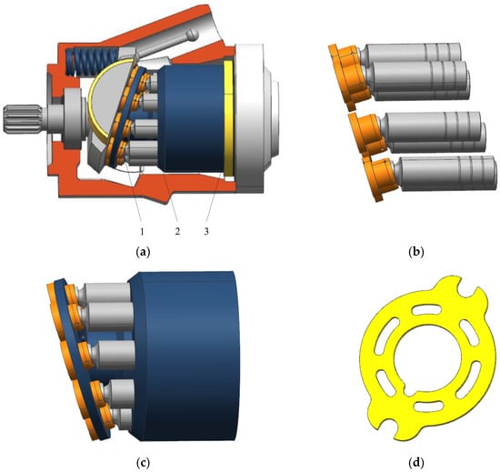
Figure 1.
Three-dimensional model of a swash-plate axial piston pump. (a) The swash-plate axial piston pump: 1—slipper pair, 2—piston pair, and 3—flow distribution pair. (b) The slipper pair composed of a slipper and a piston ball head; (c) the piston pair composed of a piston and a cylinder block; (d) the valve plate.
The flow distribution pair is an important rotating friction pair that distributes the oil flow by matching the piston pump cylinder’s body and the flow valve plate. Its clearance should be maintained at a suitable distance during operation to store the oil medium and achieve good lubrication. A clearance that is too small will cause wear or even serious burns on the end face of the cylinder or valve plate surface. If the gap is too large, leakage between the flow distribution pair will increase, leading to a decrease in the volumetric efficiency of the hydraulic pump. Because the pump’s rotating parts are intimately connected, when local wear failure of the valve plate occurs, it affects the movement of the rotating shaft, causing the IAS to show periodic fluctuations.
2.2. The Significance of IASF
Ideally, the driving torque of a hydraulic pump is in balance with the load torque, and the net torque of a piston pump’s rotation shaft can be expressed as . The torque equilibrium equation can be simplified, as in Equation (1):
where is the moment of inertia of the plunger pump (in units of kg·m2), is the rotation angle (in units of rad), and is the time (in units of s). A change in the IAS of an axial piston pump when the shaft rotates over a small angle can be expressed as in Equation (2):
where is the IAS corresponding to the point (in units of rad/s), and is the IAS corresponding to the point (in units of rad/s). The time from point to point is shown in Equation (3):
where is the mean point-to-point angular speed (in units of rad/s). Then, the mean angular acceleration of the pump shaft during this process is represented by Equation (4):
During this period, the average net torque on the input shaft of an axial piston pump is shown in Equation (5):
Formula (5) can be written as Equation (6):
Based on the above analysis, it can be concluded that wear status of the valve plate will affect the normal operation of the pump. This impact is more directly distinguished through the IASF. Fault diagnosis can be carried out based on the difference between IASF signals under normal and fault conditions.
2.3. The Acquisition of the IASF
The complete IAS measurement system is composed of two parts: hardware and software. The hardware consists of a speed-measuring gear plate (Beijing Tuopu Chengye Technology Co., Ltd., Beijing, China), a magneto-electric speed sensor (Beijing Tuopu Chengye Technology Co., Ltd., Beijing, China), a JCZ2 torque–speed sensor (Hunan Xiangyi Power Testing Instrument Co., Ltd, Changsha, China), a ADLINK PCI-9846H high-frequency data acquisition card(ADLINK Technology, Shanghai, China), and an industrial computer (National Instruments, Austin, TX, USA). The software includes LabVIEW 11.0 for online monitoring and Matlab R2021b for offline signal processing.
The process of acquiring an IASF signal is shown in Figure 2. The specific processing steps are as follows:
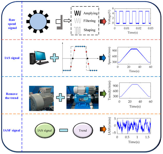
Figure 2.
The process of acquiring an IASF signal.
- (1)
- A square speed-measuring gear plate with 60 teeth is installed on the input shaft of the piston pump for synchronous rotation. The magneto-electric speed sensor is assembled on a bracket and is not in contact with the gear plate. When the hydraulic pump is running, the tooth top of the gear plate is aligned with or deviates from the sensor. An AC voltage approximated to a sine wave is induced in the coil, which is filtered and shaped by the internal hardware of the sensor to output a square-wave-pulse voltage signal.
- (2)
- The ADLINK PCI-9846H high frequency data acquisition card is utilized to conduct A/D sampling of the square wave at a sampling frequency of 500 kHz. It is processed by Matlab and the threshold of the edge trigger is set. When the falling edge is triggered, the sampling points that remain low are counted. When the rising edge is activated, the sampling points that remain high are counted. The sum of the sampling points in a square wave period is calculated, and the IAS is obtained as follows:where is the sampling frequency (in units of Hz), is the number of tooth discs, and is the number of sampling points of a signal cycle.
- (3)
- The JCZ2 torque–speed sensor and magneto-electric speed sensor coaxial monitor the pump source’s IAS signal. The JCZ2 torque–speed sensor generates a pulse speed signal for each revolution of the shaft. Therefore, the speed signal obtained synchronously via the JCZ2 torque–speed sensor can be considered a trend term of the speed. The speed signal induced via the magneto-electric speed sensor is regarded as the IAS.
- (4)
- The existence of trend terms will cause significant errors in data processing. It will cause temporal correlation statistics to lose their authenticity and will even make the fault feature’s frequency completely unreliable. The IAS signal can be generally regarded as the superposition of the speed trend term and the fluctuation term. IASF signal is calculated by subtracting the trend term from the IAS signal.
3. Proposed Method
Signal denoising is crucial for ensuring the extraction of highly reliable fault features, especially in hydraulic systems with high levels of noise and interference. The basic idea of fault diagnosis based on IAS signals is to capture the slight fluctuations generated by mechanical faults. The key step is to eliminate other irrelevant fluctuation components caused by small, high-frequency noises or external environmental interference. This paper draws on the advantages of the normal time–frequency transform (NTFT) [28] and SET to propose the SNST. The real-time frequency, phase, and amplitude are determined by analyzing the IASF signal under a background of strong, time-varying noise. Then, signal reconstruction is performed on the fault feature in order to achieve a precise time–frequency filtering effect.
3.1. A Theoretical Analysis of the SNST
The normal S-transformation of the IASF signal is defined as Equation (8):
where and are two regulatory factors, is the frequency (in units of Hz), is the signal sampling time (in units of s), and is the time shift factor (in units of s). Let
According to the rules of scale transformation and translation in the properties of the Fourier transform, as well as the Parseval theorem, it can be concluded that
where represents the complex conjugate of , and indicates the Fourier transform of . Then, Equation (11) can be found:
For a single component of the IASF signal, we have
where is a pulse function. Therefore, it can be expressed as Equation (13):
Therefore, the instantaneous phase and frequency of are defined as shown in Equation (14):
where is a biased symbol. Therefore, the definition of the SNST is shown in Equation (15):
Substituting Equation (16) into Equation (15) yields Equation (17):
Equation (15) above represents the SET. Equation (17) is called the synchronous extraction operator (SEO), which can be written as Equation (18):
According to the function , the SEO is calculated as shown in Equation (19):
The inaction principle is an important property of the normal S transform. Essentially, a certain feature component in the IASF signal can be extracted unbiased from the time–frequency transform spectrum according to the ridge line information by using the principle of inaction. Suppose that a fault feature component can be expressed as Equation (20):
The normal S-transformation of the signal satisfies the two properties expressed in Equation (21):
The time–frequency ridges of IASF signals can be obtained using the SEO operator. By using the ridge information, the feature components can be filtered via the inaction principle of the normal S-transformation to complete the time-domain feature extraction.
3.2. Diagnostic Process
The whole process of fault diagnosis for a hydraulic axial piston pump based on the SNST time–frequency analysis is shown in Figure 3. The specific diagnostic steps are as follows:
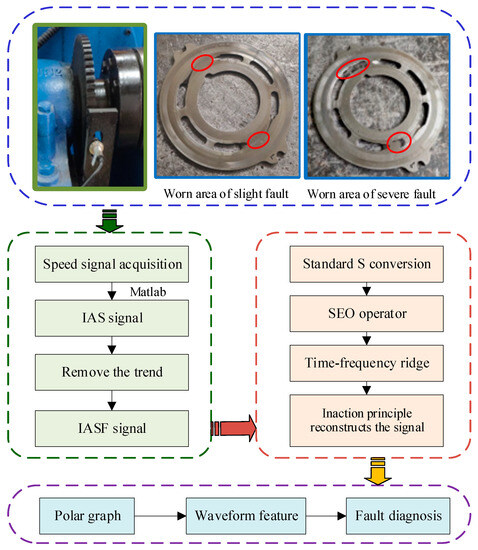
Figure 3.
Fault diagnosis process based on SNST.
- (1)
- The IAS information under non-stationary conditions was collected using a data acquisition system when the pump valve plate was under healthy, weak wear, and severe wear conditions.
- (2)
- The IAS information was processed via virtual counting and trend removal using Matlab software to obtain the IASF signal.
- (3)
- The time–frequency fault feature extraction of IASF signal based on SNST was divided into the following four steps. Firstly, the linear time–frequency spectrum of the time-domain signal was obtained by using the normal S transform. Secondly, the real-time frequency estimation was acquired from the real-time phase information. Then, the time–frequency ridge was attained via the SEO extraction operator. Finally, the line-pass filtering reconstruction of the IASF signals was realized according to the principle of inaction.
- (4)
- A fault diagnosis was carried out for the axial piston pump by using the waveform feature in the polar coordinate diagram.
4. Experimental Study and Analysis
4.1. Test System
4.1.1. Experimental Setup and Data Acquisition
Figure 4a depicts the self-developed experimental test rig, comprising a power source, hydraulic circuit, loading system, and control system. The pump to be tested is presented in Figure 4b. The speed signal was obtained on this test rig, with each sensor installed in the position shown in Figure 4c–d.
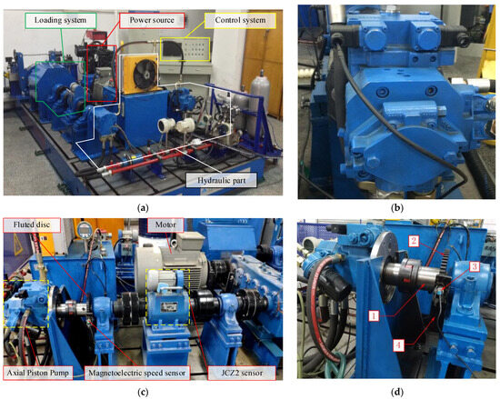
Figure 4.
Hydraulic pump failure test platform. (a) Test platform; (b) hydraulic axial piston pump; (c) speed sensors utilized for IAS data acquisition; (d) position of magneto-electric speed sensor: 1—hydraulic pump input shaft, 2—fluted disc, 3—magneto-electric speed sensor, 4—bracket.
The basic principle of the test bench is illustrated in Figure 5. The frequency converter controls the speed change of the three-phase asynchronous motor and drives the swash-plate axial piston pump to rotate. This process converts the mechanical energy generated by the motor into the hydraulic energy of the oil, which is then input into the axial piston motor. A proportional relief valve is employed to regulate the pressure of the oil outlet pipeline of the gear pump, and then load torque of the hydraulic motor is controlled to realize simulation loading. The slippage pump, which is coaxial with the axial piston pump, is applied to supplement the leakage flow generated by the hydraulic pump and motor during operation. The function of the pilot proportional relief valve is to set a maximum system pressure for the closed hydraulic circuit. When overload occurs or the system pressure exceeds the set pressure, the high-pressure chamber oil overflows through the proportional relief valve, providing safety protection. A cooling flush valve block allows part of the oil in the circuit to flow back into the oil tank, playing a heat dissipation role [29,30].
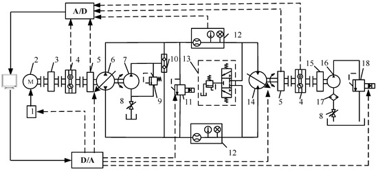
Figure 5.
Principle of the hydraulic pump failure test platform. 1—Frequency converter, 2—three-phase asynchronous motor, 3—gearbox, 4—torque and speed sensors, 5—fluted disc, 6—axial piston pump, 7—slippage pump, 8—stop valve, 9—oil replenishment relief valve, 10—oil replenishment one-way valve, 11—pilot proportional relief valve, 12—sensor group, 13—flushing valve block, 14—axial piston motor, 15—inertia wheel and brake, 16—gear pump, 17—filter, and 18—proportional relief valve.
The measurement and control principle of the test bench is presented in Figure 6. The monitoring and control system is divided into two parts: monitoring sensors and a control system. The test bench is equipped with motor current, voltage, axial piston pump, hydraulic motor speed, torque, vibration acceleration, system flow rate, pressure, and temperature sensors for the real-time monitoring of dynamic parameters. The signal of the sensor is transmitted to the industrial control computer through the wiring terminal board and data acquisition card for collection, display, and storage, providing various pieces of dynamic information for research into the performance of an electromechanical hydraulic system. The test bench control includes speed regulation and simulated loading. Speed control is achieved for the three-phase asynchronous motors via frequency converters. In the simulation loading test, the voltage control signal of the Atos proportional relief valve is given by the LabVIEW program, and the opening of the valve port is altered so as to modify the system pressure and simulate the actual load. The controlled component is connected to the analog output card PCI-1727U through the ADAM-3937 wiring terminal board.
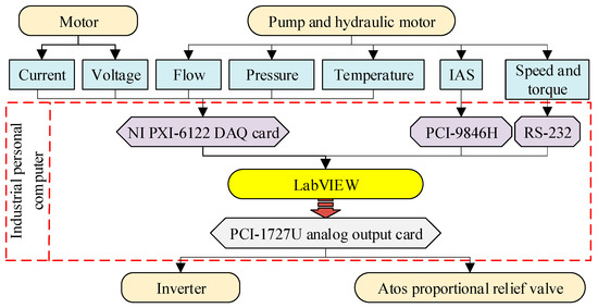
Figure 6.
The measurement and control principle of the test bench.
4.1.2. Pump Data Collection
The main parameters of each key component on the test bench are shown in Table 1. During the process of collecting experimental data, the working pressure of the axial piston pump was set at 5, 10, and 15 MPa. The speed of the axial piston pump was controlled by adjusting the input voltage of the frequency converter, and the IASF was tested. The measured speed is shown in Figure 7. The hydraulic pump operated at a speed of 300 r/min for 0–5 s, with a ramp change in speed from 300 r/min to 1000 r/min for 5–25 s, constant operation at 1000 r/min for 25–35 s, a ramp change from 1000 r/min to 300 r/min for 35–55 s, and constant operation at 300 r/min for 55–60 s. The test samples were repeatedly measured three times under the same working conditions, with each sampling time set at 60 s.

Table 1.
Main parameters of key element.
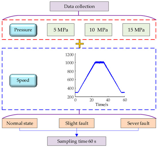
Figure 7.
Axial piston pump test parameters.
The faulty parts come from hydraulic pump maintenance enterprises. The surface shapes and positional tolerance, surface roughness, and other parts of the swash-plate axial piston pump cylinder’s body and valve plate are all normal in a healthy state. The amount of wear between the high- and low-pressure chambers of the weakly worn valve plate is about 5 μm. The amount of wear on the severely worn valve plate is approximately 15 μm. During the test, the corresponding fault state tests were carried out by replacing the normal, slightly worn, and severely worn valve plates in sequence.
4.2. Results and Analysis
Figure 8 shows the time-domain waveform of the reconstructed IASF under normal, weak wear, and severe wear conditions after the SNST line-pass filtering, when the working pressure of the axial piston pump was 10 MP. The enlarged part indicates the waveform of the reconstructed IASF signal when the axial piston pump input shaft rotated for five revolutions. It can be observed that the IASF signal exhibits considerable periodic characteristics. It is obvious that the waveform is smoother and smoother under normal conditions. When wear occurs, especially severe wear, it causes a significant high-frequency oscillation in the reconstructed IASF waveform.
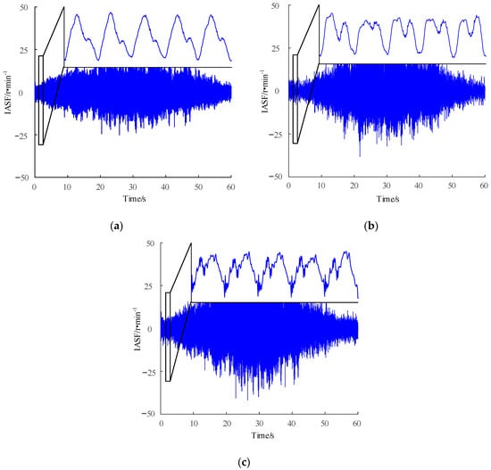
Figure 8.
Reconstruction of the IASF signal under different working conditions. (a) Normal condition; (b) slight fault; (c) severe fault.
The main cause of wear on a valve plate is cavitation, which can lead to internal regional cavitation and exacerbate the impact and vibration of the axial piston pump. Cavitation will affect transition areas of high pressure and low pressure in the valve plate’s unloading groove, which can easily extend to wear and tear in the area near the damping groove. As shown in the physical image of the worn valve plate in Figure 3, wear will make the height difference between the inner and outer sealing belt smaller, thus increasing the clearance of leakage between a piston pump cylinder and the valve plate. Changes in friction torque will be reflected in fluctuations in the pump shaft’s IAS. Therefore, an instantaneous-speed-fluctuation angle-domain waveform morphology analysis can be used for monitoring and diagnosing a valve plate’s wear status.
To quantitatively distinguish the degree of wear, the processed IASF waveform was plotted as a polar coordinate graph which can better reflect the relationship between the magnitude and angle of the speed fluctuation. Figure 9 shows polar coordinate diagrams of the reconstructed IASF signals with angle changes under normal, weak wear, and severe wear conditions.
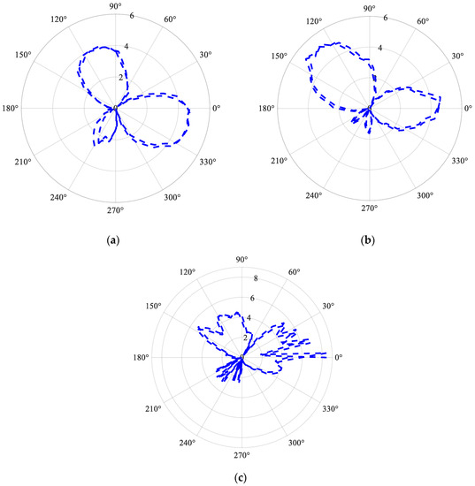
Figure 9.
Polar coordinate diagrams of the reconstructed IASF signal under different working conditions. (a) Normal condition; (b) slight fault; (c) severe fault.
The polar coordinate diagram takes the rotation angle of a piston pump as the independent variable and plots the absolute value of the reconstructed IASF signal. As can be seen from Figure 9, the dissimilarity between the fault state and the normal working conditions is reflected in the different number of oscillations generated by reconstructing the IASF value in a range from 180° to 270°. In the polar coordinate diagram, the numerical value increases from 0 and then decreases to 0, forming the number of closed-loop areas. The number under normal working conditions is one, under the weak wear condition the number is two, and the severe wear condition occurs multiple times. Therefore, the number of closed loops between 180° and 270° in the polar coordinate diagram can be used as a fault diagnosis indicator. The partial monitoring results during the experimental process are shown in Figure 10. Under severe wear conditions, an oscillation amplitude of 6 r/min will also appear near 0°. The degree of failure can be determined by monitoring whether an oscillation occurs at 0°.
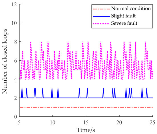
Figure 10.
Number of closed loops.
From Figure 10, it can be noted that under normal operating conditions, the number of closed loops in the 180°~270° range is always one. After the fault occurs, the number is greater than or equal to two. Therefore, a threshold of two can be set to achieve the diagnosis of piston pump valve plate faults.
The increase in the degree of wear leads to instability in the movement of fluid in the pump. In the fixed region of the IASF waveform, the number of oscillations will also increase. The SNST has extracted effective information from this part very well.
5. Conclusions
In this study, the IAS signal, which is both a running parameter and state parameter, is utilized as the information source for diagnosing faults in key hydraulic components. An SNST method for processing IAS signals is proposed and applied to the diagnosis of non-stationary operating conditions in axial piston pumps, achieving the quantification of wear faults in the valve plate. The main conclusions of this study are summarized as follows:
- (1)
- The multi-energy coupling and strong noise vibration environment of hydraulic piston pumps in non-stationary conditions make fault diagnosis extremely difficult. Through a theoretical analysis, it is concluded that when the valve plate is worn, the friction torque will change and will then be reflected in fluctuations in the instantaneous angular speed of the pump shaft. Therefore, to the use of IAS signals as information sources for monitoring and diagnosing the wear status of an axial piston pump is proposed. The traditional monitoring signal is susceptible to the non-stationary working condition of the equipment. In this paper, the IAS signals of running parameters are applied to offer a new method of fault feature extraction and fault diagnosis.
- (2)
- An SNST is proposed to perform line-pass filtering on the IASF signal of an axial piston pump. It can accurately identify the instantaneous frequency, retaining only the instantaneous frequency information that is most relevant to the time-varying characteristics. It is suitable for processing monitoring signals under non-stationary conditions.
- (3)
- A method using the polar coordinate graph is put forward for monitoring; in this method, the frequency of speed fluctuations and oscillations in the range of 180°~270° is significantly increased. Under normal working conditions, the number of closed loops in this area is one, which can be used as a monitoring indicator. Setting the threshold to two can achieve fault identification. Under severe wear conditions, an oscillation amplitude of 6 r/min may also occur near 0°. Therefore, faults can be quantified via the presence or absence of oscillations in this region.
Author Contributions
Conceptualization, J.L. and L.G.; methodology, J.L.; software, J.L.; validation, S.M. and X.Z.; formal analysis, S.M.; investigation, J.L.; resources, L.G.; data curation, S.M.; writing—original draft preparation, J.L.; writing—review and editing, S.M.; visualization, J.L.; supervision, S.M.; project administration, J.L.; funding acquisition, J.L. All authors have read and agreed to the published version of the manuscript.
Funding
This work was supported by the National Natural Science Foundation of China, grant number 51675399. This work was also funded by the Introduce High-level Talents to Start Scientific Research Funds by Shaanxi Polytechnic Institute of China, grant number BSJ 2021-11.
Data Availability Statement
The data presented in this study are available upon request from the corresponding author. The data are not publicly available due to the data confidentiality requirements of the company where the testing equipment is located.
Conflicts of Interest
The authors declare no conflict of interest.
References
- Yang, Y.; Ding, L.; Xiao, J.; Fang, G.; Li, J. Current status and applications for hydraulic pump fault diagnosis: A Review. Sensors 2022, 22, 9714. [Google Scholar] [CrossRef]
- Wu, F.; Tang, J.; Jiang, Z.; Sun, Y.; Chen, Z.; Guo, B. The remaining useful life prediction method of a hydraulic pump under unknown degradation model with limited data. Sensors 2023, 23, 5931. [Google Scholar] [CrossRef]
- Zhang, L.; Wang, S.; Yin, G.J.; Guan, C.N. Fluid–structure interaction analysis of fluid pressure pulsation and structural vibration features in a vertical axial pump. Adv. Mech. Eng. 2019, 11, 2072151946. [Google Scholar] [CrossRef]
- Geng, B.L.; Gu, L.C.; Liu, J.M. Novel methods for modeling and online measurement of effective bulk modulus of flowing oil. IEEE Access 2020, 8, 20805–20817. [Google Scholar] [CrossRef]
- Geng, B.L.; Gu, L.C.; Liu, J.M.; Shi, Y. Dynamic modeling of fluid nonlinear compression loss and flow loss oriented to fault diagnosis of axial piston pump. Proc. Inst. Mech. Eng. Part C J. Mech. Eng. Sci. 2021, 235, 3236–3251. [Google Scholar] [CrossRef]
- Zhu, Y.; Su, H.; Tang, S.; Zhang, S.; Zhou, T.; Wang, J. A novel fault diagnosis method based on SWT and VGG-LSTM model for hydraulic axial piston pump. J. Mar. Sci. Eng. 2023, 11, 594. [Google Scholar] [CrossRef]
- Chao, Q.; Xu, Z.; Tao, J.; Liu, C. Capped piston: A promising design to reduce compressibility effects, pressure ripple and cavitation for high-speed and high-pressure axial piston pumps. Alex. Eng. J. 2023, 62, 509–521. [Google Scholar] [CrossRef]
- Bensaad, D.; Soualhi, A.; Guillet, F. A new leaky piston identification method in an axial piston pump based on the extended Kalman filter. Measurement 2019, 148, 106921. [Google Scholar] [CrossRef]
- Zhang, M.Q.; Zi, Y.Y.; Niu, L.K.; Xi, S.T.; Li, Y.Q. Intelligent diagnosis of V-type marine diesel engines based on multifeatures extracted from instantaneous crankshaft speed. IEEE Trans. Instrum. Meas. 2019, 68, 722–740. [Google Scholar] [CrossRef]
- Zhao, M.; Jia, X.D.; Lin, J.; Lei, Y.G.; Lee, J. Instantaneous speed jitter detection via encoder signal and its application for the diagnosis of planetary gearbox. Mech. Syst. Signal Process. 2018, 98, 16–31. [Google Scholar] [CrossRef]
- Ding, C.C.; Zhao, M.; Lin, J.; Wang, B.X.; Liang, K.X. Transient feature extraction of encoder signal for condition assessment of planetary gearboxes with variable rotational speed. Measurement 2020, 151, 107206. [Google Scholar] [CrossRef]
- Fedala, S.; Rémond, D.; Zegadi, R.; Felkaoui, A. Contribution of angular measurements to intelligent gear faults diagnosis. J. Intell. Manuf. 2018, 29, 1115–1131. [Google Scholar] [CrossRef]
- Diamond, D.H.; Heyns, P.S.; Oberholster, A.J. Improved Blade Tip Timing measurements during transient conditions using a State Space Model. Mech. Syst. Signal Process. 2019, 122, 555–579. [Google Scholar] [CrossRef]
- Silva, R.H.G.E.; Paes, L.E.D.S.; Sousa, G.L.D.; Marques, C.; Pinto, T.L.F.D.C. Design of a wire measurement system for dynamic feeding TIG welding using instantaneous angular speed. Int. J. Adv. Manuf. Technol. 2019, 101, 5–8. [Google Scholar]
- Gomez, J.L.; Khelf, I.; Bourdon, A.; André, H.; Rémond, D. Angular modeling of a rotating machine in non-stationary conditions: Application to monitoring bearing defects of wind turbines with instantaneous angular speed. Mech. Mach. Theory 2019, 136, 27–51. [Google Scholar] [CrossRef]
- Bourdon, A.; Chesné, S.; André, H.; Rémond, D. Reconstruction of angular speed variations in the angular domain to diagnose and quantify taper roller bearing outer race fault. Mech. Syst. Signal Process. 2019, 120, 1–15. [Google Scholar] [CrossRef]
- Wang, Y.; Tang, B.P.; Qin, Y.; Huang, T. Rolling bearing fault detection of civil aircraft engine based on adaptive estimation of instantaneous angular speed. IEEE Trans. Ind. Inform. 2020, 16, 4938–4948. [Google Scholar] [CrossRef]
- Lamraoui, M.; Thomas, M.; Badaoui, M.E.; Girardin, F. Indicators for monitoring chatter in milling based on instantaneous angular speeds. Mech. Syst. Signal Process. 2014, 44, 72–85. [Google Scholar] [CrossRef]
- Alhashmi, S.A. Detection and Diagnosis of Cavitation in Centrifugal Pumps; The University of Manchester: Manchester, UK, 2005. [Google Scholar]
- Gu, L.C.; Yang, B. A cooperation analysis method using internal and external features for mechanical and electrohydraulic system. IEEE Access 2019, 7, 10491–10504. [Google Scholar] [CrossRef]
- Liu, Y.; Gu, L.C.; Yang, B.; Wang, S.H.; Yuan, H.B. A new evaluation method on hydraulic system using the instantaneous speed fluctuation of hydraulic motor. Proc. Inst. Mech. Eng. Part C J. Mech. Eng. Sci. 2017, 232, 2674–2684. [Google Scholar] [CrossRef]
- Ahmad, S.; Ahmad, Z.; Kim, J.M. A Centrifugal Pump Fault Diagnosis Framework Based on Supervised Contrastive Learning. Sensors 2022, 22, 6448. [Google Scholar] [CrossRef] [PubMed]
- Yu, G.; Yu, M.J.; Xu, C.Y. Synchroextracting Transform. IEEE Trans. Ind. Electron. 2017, 64, 8042–8054. [Google Scholar] [CrossRef]
- Hui, C.; Kang, J.X.; Chen, Y.C.; Dan, X.; Ying, Y. An Improved Time-Frequency Analysis Method for Hydrocarbon Detection Based on EWT and SET. Energies 2017, 10, 1090. [Google Scholar]
- Zhu, X.X.; Zhang, Z.S.; Gao, J.H.; Li, B.; Li, Z.; Huang, X.; Wen, G.R. Synchroextracting chirplet transform for accurate IF estimate and perfect signal reconstruction. Digit. Signal Process. 2019, 93, 172–186. [Google Scholar] [CrossRef]
- Ye, S.; Zhang, J.; Xu, B.; Hou, L.; Xiang, J.; Tang, H. A theoretical dynamic model to study the vibration response characteristics of an axial piston pump. Mech. Syst. Signal Pract. 2020, 150, 107237. [Google Scholar] [CrossRef]
- Guo, R.; Liu, Y.; Zhao, Z.; Zhao, J.; Wang, J.; Cai, W. Research on Degradation State Recognition of Axial Piston Pump under Variable Rotating Speed. Processes. 2022, 10, 1078. [Google Scholar] [CrossRef]
- Liu, L.T.; Houtse, H. Inversion and normalization of time-frequency transform. Appl. Math. Inf. Ences 2012, 6, 67–74. [Google Scholar]
- Liu, J.M.; Gu, L.C.; Geng, B.L. A practical signal processing approach for fault detection of axial piston pumps using instantaneous angular speed. Proc. Inst. Mech. Eng. Part C J. Mech. Eng. Sci. 2020, 234, 3935–3947. [Google Scholar] [CrossRef]
- Liu, J.M.; Gu, L.C.; Geng, B.L.; Shi, Y. Hydraulic pump fault diagnosis based on chaotic characteristics of speed signals under non-stationary conditions. Proc. Inst. Mech. Eng. Part C J. Mech. Eng. Sci. 2021, 235, 3468–3482. [Google Scholar] [CrossRef]
Disclaimer/Publisher’s Note: The statements, opinions and data contained in all publications are solely those of the individual author(s) and contributor(s) and not of MDPI and/or the editor(s). MDPI and/or the editor(s) disclaim responsibility for any injury to people or property resulting from any ideas, methods, instructions or products referred to in the content. |
© 2023 by the authors. Licensee MDPI, Basel, Switzerland. This article is an open access article distributed under the terms and conditions of the Creative Commons Attribution (CC BY) license (https://creativecommons.org/licenses/by/4.0/).