Abstract
Mechanical seals, such as labyrinth seals, are typically installed at the turbine outlets to prevent oil leakage. However, these seals undergo deformation because of the vibrations of the rotor, even during normal turbine operating conditions, which may cause an increase in oil leakage. In this study, the oil leakage performance of three labyrinth seals with different types of seal teeth, narrow stainless teeth (Type 1), wide aluminum teeth fixed on the body (Type 2), and fixed wide aluminum movable teeth (Type 3), were evaluated using finite element (FE) and computational fluid dynamics (CFD) analyses. Three-dimensional FE models of the rotor and oil deflectors were developed, and the plastic deformation of the teeth of the labyrinth seals was predicted when the rotor impacted the sealing teeth during turbine operation. The oil leakage was predicted using CFD analysis. The results indicated that the Type 3 seal, including movable teeth, is beneficial in preventing leakage and tooth deformation compared with the other types. The Type 2 seal is advantageous because it results in a smaller increase in gap size and greater vena contracta effects than the Type 1 seal. The results of this study could be helpful when designing and selecting the teeth of a labyrinth seal.
1. Introduction
Sealing systems, indispensable components of numerous industrial applications, are pivotal in safeguarding equipment and enhancing operational efficiency. Their primary function is to prevent the uncontrolled discharge of steam, gas, and oil, which not only leads to energy wastage but also poses significant safety hazards [1]. Mechanical seals, including intricate labyrinth seals, are mainly used particularly in high-speed rotation environments like thermal and nuclear power plants. These seals are strategically deployed at the turbine outlets, where their mission is twofold: firstly, to create an impervious barrier against oil leakage, ensuring the integrity of the power generation process, and secondly, to prevent the escape of steam or oil, a critical factor in maintaining the system’s performance and safety standards. Moreover, the importance of these sealing systems extends beyond their core functions. They also contribute as a barrier effectively blocking dust and particulate matter ingress into the turbine. Therefore, the labyrinth seals installed in a turbine not only preserve the turbine’s longevity but also contribute to the overall efficiency and reliability of the power plant.
Rotating machinery, including turbines, is one of the most popular types of machines in various applications across industries. The inherent nature of these machines involves coupled vibrations that manifest along the orthogonal direction perpendicular to the primary axis of rotation in high-speed rotational motion [2,3,4]. These vibrational oscillations, while integral to the operation of many industrial systems, may have the potential for detrimental effects on the mechanical seals employed within the machinery. Specifically, the vibrations can, over time, introduce wear and tear in the mechanical seals, culminating in structural defects that compromise their efficacy.
The impact of vibrations on mechanical seals is a critical issue in rotating machinery. Mechanical seals play a vital role in preventing the leakage of oil from machinery, but vibrations can compromise the seals’ integrity and lead to oil leakage. The gap between the mechanical seal and the rotating rotor is critical for preventing oil leakage, and any deviation in the gap size can have significant consequences. Rotor-induced vibrations can cause an increment in the gap size, which can lead to oil leakage. This can result in financial losses due to wasted resources and environmental concerns. Therefore, it is important to mitigate the adverse effects of vibrations on mechanical seals in rotating machinery.
Various labyrinth seal factors could affect a seal’s oil leakage. The geometry of the rotor and teeth is a crucial factor affecting the sealing performance. For example, Li et al. showed in their experimental study that the thickness of the tooth tip, the number of teeth, and the angle of the teeth are critical for better leakage performance [5]. Mortazavi and Palazzolo predicted the rotor-dynamic performance of a smooth stator-grooved rotor using computational fluid dynamics (CFD) analysis [6]. The results of their research showed that the introduction of the grooves on the rotor afforded a superior performance with a higher pressure drop on the aspect of the leakage. Other factors also influence the oil leakage performance. Li et al. showed that oil leakage performance varies according to the oil-throwing angle. Furthermore, Mortazavi and Palazzolo showed that toughness was also a critical factor in deciding the leakage.
To avoid damage to the sealing teeth from rotor vibration and to maintain a narrow gap between the labyrinth seal and rotor, a flexible system has been installed on the mechanical seal. Previous studies suggested inserting a spring to increase the flexibility of the labyrinth seal. Moreover, previous studies investigated the improved sealing performance of a flexible labyrinth seal using computer simulations, such as CFD analysis [7,8]. These studies showed that the improvement of the oil leakage performance was predicted in the labyrinth seal with a flexible system compared with a conventional seal without a flexible system. Chen et al. investigated the effects of tooth-bending damage on the leakage performance of labyrinth seals and demonstrated increased leakage after tooth-bending damage using CFD analysis [9]. However, no studies have investigated the sealing performance of flexible and conventional labyrinth seals considering the deformation of the sealing teeth.
Computer simulations, including finite element (FE) and CFD analysis, have been widely used in studies to investigate the mechanical behaviors of the teeth and the fluid dynamics in the seal. Yan et al. investigated the wear and deformation of labyrinth seals using FE analysis [10]. FE analysis has also been used to predict the aeroelastic stability of the straight-through labyrinth seal [11,12]. Zhang et al. used CFD to investigate the leakage performance and fluid-induced force of turbine tip labyrinth and radial annular seals [13]. In the CFD studies, Huang and Li predicted the rotor-dynamic characteristics of a rotor with labyrinth gas seals using transient CFD analysis with moving boundaries [14,15,16]. Their studies showed that a nonlinear model of aerodynamic force and fluid–solid interactions improved the prediction. CFD analysis has also been used to investigate flow characteristics in turbines with labyrinth seals in much research [17,18,19,20,21,22].
The aim of this study was to compare the oil-seal performances of labyrinth seals, before and after sealing defects, using both FE and CFD analyses. The three types of seals analyzed in this study were a narrow steel fixed seal (Type 1), thick aluminum fixed seal (Type 2), and flexible aluminum seal (Type 3). CFD models were developed from the initial geometry of the three labyrinth seals, and the oil-seal performance was predicted. The deformed geometry of the labyrinth teeth was obtained from the FE analysis. CFD models of the three mechanical seals after deformation were developed, and the oil leakage of the deformed mechanical seal was predicted using CFD analysis.
2. Materials and Methods
Three-dimensional computer-aided design (CAD) models of the labyrinth seals with different geometries and mechanical characteristics were developed to protect against lubricant oil leakage from the turbine. Two of the three seals (Types 1 and 2) consisted of five fixed sealing teeth, and one (Type 3) consisted of three fixed teeth and two sets of two movable teeth. The gap size between the sealing teeth and rotor was set to be 0.5 mm for the fixed teeth, while the gap was set to be 0.05 mm for the movable teeth. For the Type 1 seal, stainless steel was used, while aluminum was used for both the Type 2 and 3 seals. The geometries of the three labyrinth seals are shown in Figure 1.
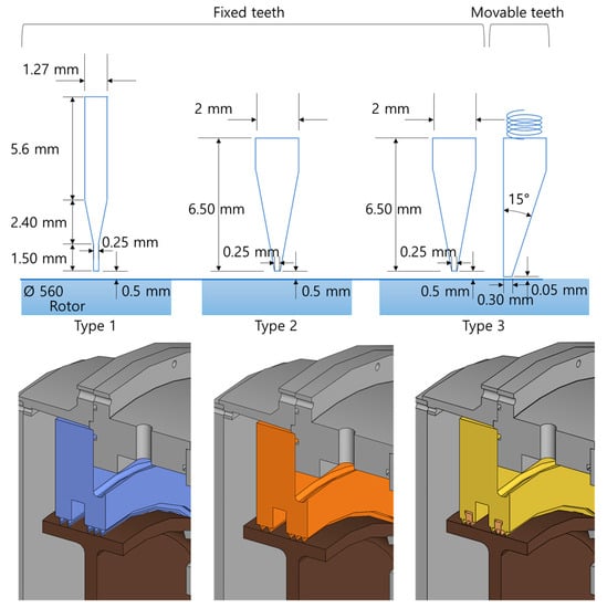
Figure 1.
Geometries of the three types of labyrinth seals analyzed in this study.
2.1. Finite Element Analysis
Figure 2 depicts the FE model for each of the three labyrinth seals developed using CAD. The rotor and sealing teeth were revolving parts. The FE models for the three labyrinth seals and rotor were developed using a revolution of 60° from the Y-axis. Brick elements were used in all the FE models. However, for efficient computation, the inner parts of the rotor and seal bodies were assumed to be rigid.
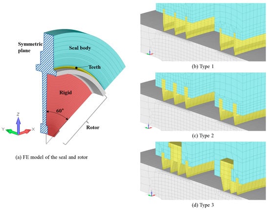
Figure 2.
FE model of the three labyrinth seals.
The material property of carbon steel was used for the rotor for all three FE models. For the Type 1 seal, the material properties of stainless steel were adopted for the teeth, whereas for the Type 2 and 3 seals, the teeth were assumed to be an Al–Mg alloy. Both the fixed and movable sealing teeth were assumed to be Al–Mg alloys in the Type 3 seal. Bilinear elastoplastic material properties were used for all the materials. Thus, the material behaved plastically under stresses greater than its yield strength. All the material properties used for the FE models are listed in Table 1.

Table 1.
Material properties for FE models of the three labyrinth seals.
The seals considered in this study were intended to protect against lubricant oil leakage; thus, the outer surfaces of the rotor and sealing teeth were covered with oil. Three-dimensional surface-to-surface contact conditions without friction were applied between the sealing teeth and outer rotor surface in all the FE models of the three seals. In addition, the same contact conditions were applied between the movable teeth and seal body of the Type 3 labyrinth seal. A spring with a spring coefficient of 20 N/mm between the movable teeth and seal body enabled the motion of the movable teeth and prevented their deformation.
Boundary conditions for a symmetrical analysis against the YZ plane were applied. Thus, the nodes in the YZ plane were constrained in the X-direction. The outer surface of the sealing body was fixed in all directions, and the fixed teeth were attached to the sealing body. The movable teeth were constrained to translate in the Z-direction (vertically). The rotational motion of the rigid section of the rotor was constrained in all directions. Translational motions in the X- and Y-directions of the rotor were constrained, and the Z-directional translation was controlled.
An FE analysis was conducted to analyze the deformation of the sealing teeth caused by the translational motion of the rotor (vibration). For an efficient FE analysis, the analyses were conducted in three steps: static, dynamic, and static. For the first step, a static analysis was performed, and the rotor was translated in the positive Z-direction by 0.5 mm to enable the rotor to touch the fixed seals. In the second step, the rotor was moved in the positive Z-direction by 0.2 mm with 12 mm/s for 0.0167 s, and then the rotor was moved back to the 0.5 mm location in the third step. The amount and speed of translational motion were obtained from the operating conditions of the turbine in the power plant. Abaqus/Standard 2022 (Dassault Systems, SIMULIA Corp., Johnston, RI, USA) was used for the FE analysis.
2.2. Computational Fluid Dynamics Analysis
Two-dimensional axisymmetric steady-state CFD analysis was performed to predict oil leakage through the mechanical seals for an efficient analysis while considering the mechanical and geometrical characteristics of the seals. Based on the CAD models of the three labyrinth seals, CFD analysis models were developed with 122,205, 98,092, and 157,916 cells for the Type 1, 2, and 3 seals, respectively (shown in Figure 3). The grid system was generated to satisfy a Y+ value of 30 for all models to simulate accurate fluid flow around the teeth.
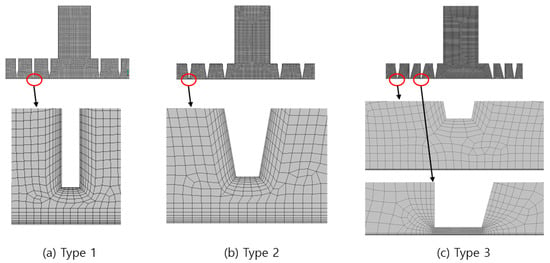
Figure 3.
Grid system for CFD models of the three labyrinth seals.
Additional dummies were considered upstream and downstream of the mechanical seal to generate stable fluid dynamics and avoid the backward flow of oil. The dummy length was five times the gap height between the seal body and the rotor. The governing equations for the continuity equation and momentum conservation equation for swirl velocity were used, and the standard k-epsilon turbulence model, which is the most common model used in CFD analysis, was used for the turbulence model. Pressure inlet and outlet conditions of 196,133 and 101,325 Pa were applied for the analysis. A moving wall condition corresponding to 3600 rpm of the rotor was applied to the surface that touched the outer wall of the rotor. No-slip wall conditions were applied to all other surfaces, as shown in Figure 4.
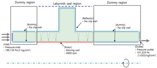
Figure 4.
CFD analysis conditions to predict lubricant oil leakage.
Oil leakage was predicted for the initial and deformed conditions of the sealing teeth. In this study, lubricant oil with a density of 0.84 g/cc and viscosity of 0.026880 Pa∙s was used. While undeformed geometries of the three sealing teeth were obtained from their original design, the deformed geometries of the three sealing teeth by the rotor vibration were obtained from the results of the FE analysis. Subsequently, the CFD models of the three deformed labyrinth seals were developed based on the deformed geometries (shown in Figure 5). The same analysis conditions were applied to both the undeformed and deformed CFD models. ANSYS 18.0 (ANSYS Inc., Canonsburg, PA, USA), including SpaceClaim, ANSYS meshing, and ANSYS/Fluent, was used to generate the CFD models and analyses.
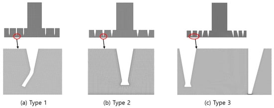
Figure 5.
Grid system for CFD models of the three deformed labyrinth seals.
3. Results
3.1. Results of Finite Element Analysis
Reaction forces were predicted using a two-step analysis. The predicted maximum reaction forces were 36.4, 45.5, and 25.4 kN for the Type 1, 2, and 3 seals, respectively. As shown in Figure 6, for the Type 1 seal, the maximum value of the reaction force was predicted immediately after the beginning of the second step; however, for the Type 2 and 3 seals, the maximum values were predicted at the end of the second step. As shown in Figure 7, stress was also predicted when the rotor contacted the sealing teeth. The predicted maximum stresses were 278.5, 101.0, and 99.6 MPa for the Type 1, 2, and 3 labyrinth seals, respectively (Figure 7). The maximum stress did not exceed the yield strength.
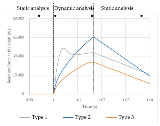
Figure 6.
Predicted reaction forces during three-step FE analysis.

Figure 7.
Stress distribution on the outer rotor surface when the rotor translated towards the positive vertical direction by 7 mm.
As shown in Figure 8, bending deformation was predicted for the teeth of the Type 1 seal, and mushrooming deformation of the fixed sealing teeth was predicted for the fixed teeth of the Type 2 and 3 seals. During the translational motion of the rotor, the maximum displacements of the fixed sealing teeth were predicted to be 0.74, 0.27, and 0.27 mm in the Type 1, 2, and 3 labyrinth seals, respectively. However, the plastic deformations in the vertical direction, which increased the gap size between the sealing teeth and rotor, were 0.30, 0.20, and 0.20 mm, respectively. Plastic deformation was only predicted for the fixed sealing teeth and not for the movable teeth.
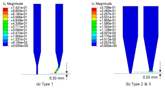
Figure 8.
Maximum deformation of the fixed sealing teeth.
3.2. Results of Computational Fluid Dynamics Analysis
The velocity vectors of fluid flow in the undeformed and deformed Type 1 and 2 labyrinth seals are shown in Figure 9. The oil in the mechanical seal flowed through the gap between the sealing teeth and the rotor at a high speed, but oil that could not move through the gap swirled in the space between the sealing teeth. The oil that moved to the next space was recirculated. Although the overall flow velocity in the seal region was similar to the flow velocity before and after the deformation of the sealing teeth, the changes in the flow direction at the entrance of the gap were predicted based on the deformation of the sealing teeth.
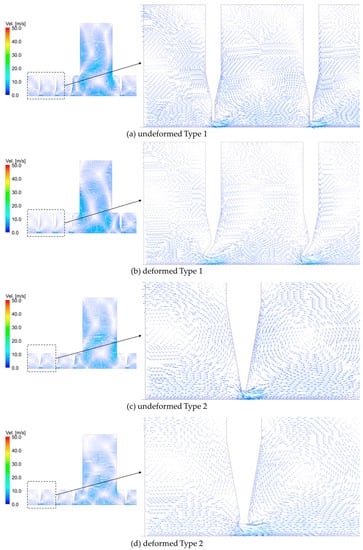
Figure 9.
The velocity vector of the lubricant oil in the Type 1 and 2 seals.
Table 2 lists the predicted oil leakages for the undeformed and deformed seals. The predicted oil leakages were 3.272, 3.299, and 0.057 kg/s for the Type 1, 2, and 3 seals, respectively. These values increased to 4.969, 4.240, and 0.059 kg/s, respectively. The Type 1 labyrinth seal, in which the greatest increase in the gap between the sealing teeth and rotor was predicted, showed an increase in oil leakage of 52% with sealing teeth deformation. Only a 4% increase in oil leakage was predicted after tooth deformation in the Type 3 seal, in which no plastic deformation was predicted for the movable teeth, whereas deformation was predicted in the fixed teeth because of the translation of the rotor.

Table 2.
Predicted oil leakage in the undeformed and deformed seals.
4. Discussion
Computer simulations, including FE and CFD analyses, have been used to investigate the fluid flow, leakage, deformation, and damage of labyrinth seals in previously published studies [23,24,25,26,27]. The gap size and flow characteristics are critical factors for the performance of a labyrinth seal [9,23,28,29]. This study investigated the deformation of the sealing teeth of a labyrinth seal according to its material and geometry using the FE analysis computer simulation method for structural analysis. Subsequently, the changes in the flow characteristics and leakage according to the deformation of the teeth and changes in the gap size were determined using CFD analysis.
Wallen et al. indicated that sealing teeth are damaged during friction between the teeth and rotor [30]. Furthermore, they also identified two deformation shapes of damaged labyrinth seal teeth: mushrooming and bending deformations. They proposed that mushrooming deformation is typical for metallic sealing teeth, whereas bending deformation is typical for thermoplastic sealing teeth. In this study, impact was used instead of rubbing to generate tooth damage. However, the FE analysis predicted bending and mushrooming deformations according to the geometry and material of the sealing teeth. As shown in Figure 5, bending damage to the sealing teeth was predicted for the Type 1 seal, whereas mushrooming damage was predicted for the fixed sealing teeth of the Type 2 and 3 seals. Although metallic teeth were used for all three labyrinth seals, the shapes of the damaged sealing teeth differed based on their geometrical and material characteristics. Thick-sealed teeth with a more ductile material can be deformed into a mushrooming shape. However, thin teeth with more brittle materials can experience bending deformation.
The gap between the sealing teeth and rotor increases owing to wear on the rotor. The predicted stress on the rotor during translation was lower than its yield strength. Therefore, no permanent deformation on the outer surface of the rotor was predicted for any of the three types of labyrinth seals considered in this study. However, a higher stress on the outer surface of the rotor was predicted for the Type 1 labyrinth seal than for the others. Therefore, it was anticipated that wear or damage to the rotor could be more rapid in the Type 1 labyrinth seal than in the others when repeated vibrations or greater vibrations than those considered in this study were applied. Moreover, wear or damage to the rotor enlarges the gap between the sealing teeth and the rotor, resulting in an increase in oil leakage.
The fluid is confined in the labyrinth seal because of the flow resistance in the narrow gap between the sealing teeth and rotor. When the fluid enters a narrow gap with a high velocity, the flow direction cannot be abruptly changed at the entrance of the gap. Thus, the clearance of the fluid streamline at the entrance of the gap was larger than that in the region where a parallel streamline was observed. This phenomenon is called the vena contracta effect, which increases the flow resistance and helps prevent leakage of the inner fluid. Therefore, the vena contracta effect is an important factor in the performance of labyrinth seals [9,27,28].
For the Type 1 labyrinth seal, the bending deformation of the sealing teeth increased oil leakage compared to that of the as-installed condition. It was deduced that the primary reason for this was the increase in gap size caused by the plastic deformation of the sealing teeth. However, as shown in Figure 9, the direction of the fluid flow at the gap entrance between the sealing teeth and rotor was flatter in the deformed Type 1 seal compared with that of the undeformed Type 1 seal. This implies that the vena contracta effect was reduced with deformation in the Type 1 seal. Using CFD analysis, Chen et al. showed that an increase in the gap caused by the bending of the sealing teeth reduced the vena contracta effect [9]. Although the direction of tooth bending in this study differed from that in the previous study, the same phenomenon was predicted in the results of this study.
The mushrooming deformation of the sealing teeth was predicted for the Type 2 and 3 labyrinth seals. The deformed shape of the sealing teeth, similar to that of a mushroom, led to changes in the fluid flow toward the rotor at the entrance of the gap between the sealing teeth and rotor. This implies that the vena contracta effect increased with the mushrooming deformation of the sealing teeth. This increased vena contracta effect may have compensated for the increase in oil leakage caused by the enlarged gap size resulting from the deformation of the sealing teeth. Previously published studies have also shown that the leakage rate is mainly dependent on the gap size but is also affected by the mushroom radius. Therefore, the Type 2 sealing teeth were more efficient than the Type 1 sealing teeth in reducing oil leakage.
This study has several limitations. Damage to the sealing teeth is generally caused by repeated compression and rubbing [9,26,30]. Thus, the deformation shape of the sealing teeth under repeated loads can differ from that of an instantaneous load. In addition, changes in the gap size due to vibrations affect leakage. In this study, a two-dimensional steady-state analysis was conducted to predict oil leakage for three labyrinth seals. Despite these limitations, the authors simulated the two typically damaged shapes of the sealing teeth in labyrinth seals using impactive compressive force. In addition, the differences in oil leakage of the three labyrinth seals were compared under the same analysis conditions.
5. Conclusions
Based on the results of this study, the authors concluded that movable sealing teeth are helpful not only in avoiding damage to the sealing teeth with the vibration of the rotor but also in reducing oil leakage while maintaining a minimal gap size between the sealing teeth and rotor. In a case where the movable sealing teeth cannot be applied, thicker sealing teeth with softer and more ductile material, such as those of the Type 2 labyrinth seal, are more beneficial for reducing oil leakage. This is in contrast to the Type 1 labyrinth seal, which consists of thin teeth with brittle material. Less of an increase in gap size with mushrooming deformation of the sealing teeth was expected in the Type 2 labyrinth seal than in the Type 1 seal. Moreover, the vena contracta effect, which helps reduce oil leakage, was increased because of the mushrooming deformation in the Type 2 seal. The results of this study could be useful in the design of labyrinth seals and when selecting the sealing teeth for labyrinth seals.
Author Contributions
Conceptualization, W.M.P. and H.G.L.; data curation, S.M.S.; methodology, W.M.P., S.M.S. and D.K.C.; project administration, C.C.; writing—original draft, W.M.P.; writing—review and editing, C.C. All authors have read and agreed to the published version of the manuscript.
Funding
This study was financially supported by Korea East-West Power Co., Ltd.
Data Availability Statement
Data are available on request due to confidentiality.
Acknowledgments
This study was financially supported by Korea East-West Power Co., Ltd.
Conflicts of Interest
There are no conflict of interest to declare.
References
- Zheng, Y.; Wang, Y.; Dai, Y. Numerical simulation and characteristics analysis of the turbine shaft end spiral groove mechanical seal. In Proceedings of the 2012 3rd International Conference on Digital Manufacturing and Automation, ICDMA 2012, Guilin, China, 31 July–2 August 2012. [Google Scholar]
- Sun, D.F.; Sun, J.J.; Ma, C.B.; Yu, Q.P. Frequency-Domain-Based Nonlinear Response Analysis of Stationary Ring Displacement of Noncontact Mechanical Seal. Shock Vib. 2019, 2019, 7082538. [Google Scholar] [CrossRef]
- Amarnath, M.; Shrinidhi, R.; Ramachandra, A.; Kandagal, S.B. Prediction of defects in antifriction bearings using vibration signal analysis. J. Inst. Eng. Mech. Eng. Div. 2004, 85, 88–92. [Google Scholar]
- Li, X.; Fu, P.; Chen, K.; Lin, Z.; Zhang, E. The contact state monitoring for seal end faces based on acoustic emission detection. Shock Vib. 2016, 2016, 8726781. [Google Scholar] [CrossRef]
- Li, G.; Zhang, Q.; Lei, Z.; Huang, E.; Wu, H.; Xu, G. Leakage performance of labyrinth seal for oil sealing of aero-engine. Propuls. Power Res. 2019, 8, 13–22. [Google Scholar] [CrossRef]
- Mortazavi, F.; Palazzolo, A. CFD-based prediction of rotordynamic performance of smooth stator-grooved rotor (SS-GR) liquid annular seals. In Proceedings of the ASME Turbo Expo, Charlotte, NC, USA, 26–30 June 2017; Volume 7A-2017. [Google Scholar]
- Choi, Y.H.; Kwak, H.S.; Lee, C.R.; Kim, C. Development of an Advanced Oil Deflector Used in Thermoelectric Power Plant. J. Korean Soc. Precis. Eng. 2016, 33, 661–668. [Google Scholar] [CrossRef]
- Kim, J.H.; Bae, J.H.; Lee, C.-R.; Kim, C. Development of Flexible Packing Ring in Steam Turbine for Reduction of Leakage by using CFD Flow Analysis. J. Korean Soc. Precis. Eng. 2013, 30, 741–748. [Google Scholar] [CrossRef]
- Chen, Y.; Li, Z.; Li, J.; Yan, X. Effects of tooth bending damage on the leakage performance and rotordynamic coefficients of labyrinth seals. Chinese J. Aeronaut. 2020, 33, 1206–1217. [Google Scholar] [CrossRef]
- Yan, X.; Wang, H.; He, K. Numerical investigations into the rubbing wear behavior of honeycomb seal. J. Mech. Sci. Technol. 2023, 37, 4375–4390. [Google Scholar] [CrossRef]
- Wang, N.; Wang, Y.; Tian, A. Influence of structure parameters on aeroelastic stability for labyrinth seal based on energy method. Propuls. Power Res. 2018, 7, 288–295. [Google Scholar] [CrossRef]
- Wang, N.; Wang, Y. Aeroelastic Stability of Labyrinth Seal with Different Structure Parameters. In Proceedings of the MATEC Web of Conferences, Wuhan, China, 10–13 May 2018; Volume 179. [Google Scholar]
- Zhang, W.F.; Yang, J.G.; Li, C.; Tian, Y.W. Comparison of leakage performance and fluid-induced force of turbine tip labyrinth seal and a new kind of radial annular seal. Comput. Fluids 2014, 105, 125–137. [Google Scholar] [CrossRef]
- Huang, D.; Li, X. Rotordynamic characteristics of a rotor with labyrinth gas seals. Part 1: Comparison with Child’s experiments. Proc. Inst. Mech. Eng. Part A J. Power Energy 2004, 218, 171–178. [Google Scholar] [CrossRef]
- Huang, D.; Li, X. Rotordynamic characteristics of a rotor with labyrinth gas seals. Part 2: A non-linear model. Proc. Inst. Mech. Eng. Part A J. Power Energy 2004, 218, 179–186. [Google Scholar] [CrossRef]
- Huang, D.; Li, X. Rotordynamic characteristics of a rotor with labyrinth gas seals. Part 3: Coupled fluid-solid vibration. Proc. Inst. Mech. Eng. Part A J. Power Energy 2004, 218, 187–197. [Google Scholar] [CrossRef]
- Li, Z.; Li, J.; Feng, Z. Labyrinth seal rotordynamic characteristics part I: Operational conditions effects. J. Propuls. Power 2016, 32, 1199–1211. [Google Scholar] [CrossRef]
- Li, Z.; Li, J.; Feng, Z. Labyrinth seal rotordynamic characteristics part II: Geometrical parameter effects. J. Propuls. Power 2016, 32, 1281–1291. [Google Scholar] [CrossRef]
- Huo, C.; Sun, J.; Song, P.; Sun, W. Influence of tooth geometrical shape on the leakage and rotordynamic characteristics of labyrinth seals in a cryogenic liquid turbine expander. Int. J. Refrig. 2023, 145, 105–117. [Google Scholar] [CrossRef]
- Xue, W.; Fang, Z.; Wang, T.; Li, Z.; Li, J. Investigation on the Rotordynamic Characteristics of Labyrinth Seal with Swirl Brakes. Hsi-An Chiao Tung Ta Hsueh/J. Xi’an Jiaotong Univ. 2022, 56, 105–116. [Google Scholar] [CrossRef]
- Wang, T.; Li, Z.; Li, J. Investigation on the Rotordynamic Characteristics of Straight-Through Labyrinth Seal Using Bulk-Flow Model. Hsi-An Chiao Tung Ta Hsueh/J. Xi’an Jiaotong Univ. 2021, 55, 25–33. [Google Scholar] [CrossRef]
- Wang, T.; Li, Z.; Li, J. Rotordynamic Characteristics of the Straight-Through Labyrinth Seal Based on the Applicability Analysis of Leakage Models Using Bulk-Flow Method. J. Eng. Gas Turbines Power 2022, 144, 011028. [Google Scholar] [CrossRef]
- Du, Q.; Zhang, D. Numerical investigation on flow characteristics and aerodynamic performance of a 1.5-stage SCO2 axial-inflow turbine with labyrinth seals. Appl. Sci. 2020, 10, 373. [Google Scholar] [CrossRef]
- Baek, S.I.; Ahn, J. Optimizing the geometric parameters of a straight-through labyrinth seal to minimize the leakage flow rate and the discharge coefficient. Energies 2021, 14, 705. [Google Scholar] [CrossRef]
- Kim, J.H.; Ahn, J. Large eddy simulation of leakage flow in a stepped labyrinth seal. Processes 2021, 9, 2179. [Google Scholar] [CrossRef]
- Zhang, X.; Jiao, Y.; Qu, X.; Huo, G.; Zhao, Z. Simulation and Flow Analysis of the Hole Diaphragm Labyrinth Seal at Several Whirl Frequencies. Energies 2022, 15, 379. [Google Scholar] [CrossRef]
- Dogu, Y.; Sertçakan, M.C.; Gezer, K.; Kocagül, M.; Arican, E.; Ozmusul, M.S. Labyrinth seal leakage degradation due to various types of wear. J. Eng. Gas Turbines Power 2017, 139, 062504. [Google Scholar] [CrossRef]
- Dogu, Y.; Sertçakan, M.C.; Bahar, A.S.; Pişkin, A.; Arican, E.; Kocagül, M. Computational Fluid Dynamics Investigation of Labyrinth Seal Leakage Performance Depending on Mushroom-Shaped Tooth Wear. J. Eng. Gas Turbines Power 2016, 138, 032503. [Google Scholar] [CrossRef]
- Yan, X.; Dai, X.; Zhang, K.; Li, J.; He, K. Effect of teeth bending and mushrooming damages on leakage performance of a labyrinth seal. J. Mech. Sci. Technol. 2018, 32, 4697–4709. [Google Scholar] [CrossRef]
- Whalen, J.K.; Alvarez, E.E.; Palliser, L.P. Thermoplastic Labyrinth Seals For Centrifugal Compressors. In Proceedings of the 33rd Turbomachinery Symposium, Houston, TX, USA, 20–23 September 2004; Turbomachinery Laboratories, Texas A&M University: College Station, TX, USA, 2004. [Google Scholar]
Disclaimer/Publisher’s Note: The statements, opinions and data contained in all publications are solely those of the individual author(s) and contributor(s) and not of MDPI and/or the editor(s). MDPI and/or the editor(s) disclaim responsibility for any injury to people or property resulting from any ideas, methods, instructions or products referred to in the content. |
© 2023 by the authors. Licensee MDPI, Basel, Switzerland. This article is an open access article distributed under the terms and conditions of the Creative Commons Attribution (CC BY) license (https://creativecommons.org/licenses/by/4.0/).