Article

Determination of the Friction Coefficient in the Ring Test for Selected Lubricants Dedicated to the Hot Forging Process of Precision Steel Products

1
Department of Metal Forming, Welding and Metrology, Wroclaw University of Science and Technology, Lukasiewicza Street 5, 50-370 Wroclaw, Poland
2
Schraner Polska, Lotnicza 21g, 99-100 Łęczyca, Poland
*
Author to whom correspondence should be addressed.
Lubricants 2023, 11(9), 399; https://doi.org/10.3390/lubricants11090399
Submission received: 16 August 2023 / Revised: 8 September 2023 / Accepted: 10 September 2023 / Published: 13 September 2023

Abstract

:
This paper concerns an analysis of the tribological conditions and the effect of the use of seven lubricating agents dedicated to a process of precision forging on a hammer in multiple systems. In particular, it performs a review of the most popular methods of determining the friction coefficient in the aspect of the obtained results. On this basis, the selected method of friction coefficient determination was a hot ring upsetting test for two forging materials: carbon steel (16MnCrS5) and stainless steel (316Ti). The test samples were prepared in the shape of a ring with precisely defined dimensions, and, next, they were subjected to an upsetting process on a hydraulic hammer under conditions similar to those present in an industrial forging process, and the characteristic geometrical features and friction coefficients were determined. Additionally, measurements of the geometrical changes were made with the use of 3D scanning for the extreme friction coefficient values in order to perform their comparison. The obtained results showed that for carbon steel the lowest achieved value was in the case of Lubrodal F185 (µ = 0.24) A and the highest for Lubr_hot_press 123HD (µ = 0.32); in turn, for stainless steel the lowest value µ = 0.19 was achieved for Graphitex CR 7 and the highest for Graphitex CR720K (µ = 0.29). Moreover, for these conditions, numerical modeling was conducted in the Forge 3.0 NxT program, in order to analyze the obtained results and verify the correctness and agreement of the friction coefficients determined in the ring test, on the basis of the geometrical changes. The data obtained in the computer simulation confirmed the possibility of obtaining a good agreement between the FEM (Finite Elements Method) and experimental trials, as the modeling provides reliable information on the plastic deformations and can be used as an alternative method of examining the friction conditions in industrial forging processes.

1. Introduction

The role of friction in plastic forming processes, especially in the case of processes involving high plastic deformations, such as in the case of forging processes, is quite important, as the friction phenomenon is usually the basic factor that, for many plastic forming processes, has a decisive effect on the manner of material deformation (causing changes both on its surfaces and in its internal structure) as well as the forming forces. The effect of friction, apart from a few exceptions, is usually negative [1]. On the one hand, it causes, e.g., errors in the material flow, tool wear, a significant load increase, internal and surface defects, and, as a direct consequence, the heterogeneity of the deformation field and the temperature distribution field. On the other hand, it is the friction that makes it possible to carry out most of the plastic forming process. For this reason, the basic issue in plastic forming process is the properly defined fraction conditions, which is connected with the recognition and determination of all the factors and phenomena affecting the friction value [2,3].
Several theories have been elaborated about the creation of the friction forces; however, the process and mechanism of this phenomenon is still difficult to describe [4]. The friction present in plastic forming processes differs from the friction occurring in machine components, mainly in the pressure value, which in plastic forming can reach 2500 MPa (250 kG/mm2), while in machines it only reaches 10 ÷ 50 MPa (1 ÷ 5 kG/mm2). On the surface of the rubbing elements in machine parts, the shifting of the metal particles is similar in all the contact points, whereas in plastic forming the sizes and speeds of the shift are different in different contact points. In order to deform a metal in the presence of friction, it is necessary to apply a much higher force than that implied by the deformation resistance of the given material. Together with the increase in friction, both the force necessary for the deformation and the energy consumption increase as well. Friction is one of the causes of deformation non-uniformity [5]. In the areas of an object located near the friction face, the operation of the friction forces hindering the deformation is bigger than in the areas distant from the contact, and, additionally, we should also consider the lubricant itself [6].
The analysis of the issue of friction and lubrication, which, with the consideration of the temperature changes, should be treated globally as the tribological conditions of the process, is very difficult, as the surface phenomena accompanying these processes depend on a series of factors operating on both the material itself and the tools. What is more, the character of the particular factors is divergent and not entirely recognized. For this reason, more and more tests have been conducted of the effect of the particular factors, and attempts have been made at their consideration in the description of the friction force or the friction coefficients. Friction in the plastic forming process is not a simple issue, as the real contact surface does not correspond to the nominal one, and it consists of many micro-contacts, whose surfaces increase with the pressure increase. The surface pressures in plastic forming processes, as has been mentioned, reach very high values, of the order of a few thousand MPa; what is more, during the material forming, heterogeneous pressures occur, as well as increased friction forces between the tool and the deformed material [7]. Also, the rates and the material shift vectors are not uniform on the whole surface. What is more, we should consider the use of layers/coatings on the material, in which case we do not deal with the working surface of the given material itself but rather its surface layer, and this is the way the tribological phenomena should be considered [8,9,10]. The properties and the role of lubricating agents, as well as the lubrication technique in the aspect of ensuring optimal tribological conditions, have been analyzed in detail in the study [11].
There are a few types of friction, and the phenomenon itself can be presented in respect of the type of motion, state of motion, location, material and contact. Usually, on the contact surface of the processed material we can differentiate between the following friction types: dry friction, boundary friction and fluid friction. The last one occurs when the friction faces are separated with a lubricant, such as grease, a gas or a liquid. If the thickness of the layer separating the cooperating elements equals 0.1 of the value coefficient μ, then the external friction is changed into the internal friction of the lubricant. In layers with this thickness, we deal with the hydrodynamic properties of the liquid.
In the case of plastic forming, especially forging, we usually deal with boundary friction, which depends on many factors, such as the deformation rate of the processed material, the state of initial stress, the process temperature, the state of the processed material’s surface, the type of lubricant, the type of the formed or applied layer and the type of tool material and its surface, as well as the type of the material processed through plastic forming and its properties [12,13]. The difficulty of the friction phenomenon results from its complexity. In the surface layer of movable objects, there are a series of occurring mechanical, physical and chemical processes connected with lubrication as well as surface wear. For this reason, a lot of attention is still devoted to this issue in order to determine the tribological conditions and describe the friction coefficient/factor, by way of searching for methods that, on the one hand, enable an easy determination of friction and, on the other hand, most accurately reflect the character of the industrial process, so that similar operation conditions can be preserved [14,15,16,17].
Tests that simulate the tribological conditions in principle aim at determining the values of friction coefficients under the plastic deformation conditions of the whole area or in the case of strictly localized plastic deformation. Difficulties arise in the interpretation of the results obtained in the particular simulation tests, as in real processes we often deal with high values of nominal and contact pressures, whereas the available devices (tribometers, based on ball/pin on disc or similar techniques) for friction determination consider very low pressures (up to a few MPa), which are inadequate compared to those present in forging processes (300–2000 MPa). Moreover, it is important that the selected method of testing the tribological conditions well represents the geometry of the given real process or its simulation and also that the laboratorial results be verified under industrial conditions [18,19]. In the case of plastic forming processes, for the determination of friction the most commonly applied method is the friction law elaborated by G. Amontons, which is given as the friction law (model) by Coulomb and described by means of the following formula:
τ = µ p n
where τ—contact stress on the contact surface and pn—normal pressure.
Another popular model is the so-called constant friction model, the development of which is attributed to Tresca, in which the contact stress τ on the contact surface depends on the material’s yield stress with pure shear k, according to the following dependence:
τ = mk
where m—the fraction coefficient on the contact surface (sometimes referred to as the tool roughness coefficient), which assumes values in the scope of 0 ≤ m ≤ 1.

2. Review of Selected Experimental Methods of Determining the Friction Coefficient and the Tribological Conditions

Due to the need to define the effect of friction on the course of deformations, as well as their amount and quality, which is caused by a big participation of friction forces in plastic forming processes of metals, many analytical–experimental and experimental methods have been developed, which make it possible to determine the friction conditions through modeling the plastic forming process in a small scale [20]. Unfortunately, determining the friction coefficient by means of the methods elaborated so far is burdened with a certain error. This results from the fact that the friction coefficient is an intermediate quantity, resulting from the performed measurements of other measurable quantities. Additionally, the value of the calculated friction coefficient is strictly dependent on the assumed friction method or hypothesis [20,21,22]. To that end, Equations (1) and (2) are usually used, whose proper application requires the knowledge of the friction coefficient μ or friction factor m. There are many methods of determining the frictional resistance, which can be divided into two basic groups:
  • Analytical–experimental methods;
  • Experimental methods.
In analytical–experimental methods, the value of the friction coefficient (factor) is determined from the dependences describing the force or work of plastic deformation in the examined plastic forming process, which, with certain calculation simplifications, makes the friction values inaccurate. The experimental methods are used to determine the friction coefficient (factor) depending on the measured quantity, which makes them more precise.

2.1. Method Based on Upsetting a Wedge Sample

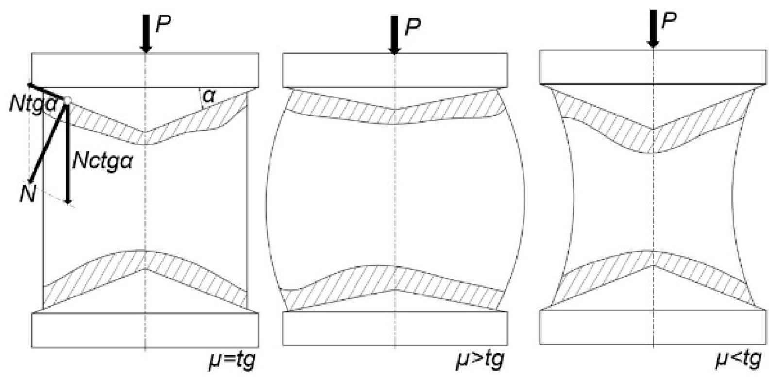
The method elaborated by E.F. Szarapin [23,24] consists of deforming a flat bar between anvils, of which the lower one is immovable and flat and the upper one upsets the sample into a wedge with the inclination angle of α (Figure 1). Before the test, vertical perpendicular lines should be plotted onto the side surfaces of the flat bar. The lines’ purpose is to determine the location of the neutral plane (A-B). During the test, the vertical lines, under the effect of the friction forces, become curved beyond the A-B line, which divides the material flow into zone a and zone b. The area of the presence of the neutral plane is dependent on the friction force resistances and the inclination value α [25].
Knowing the distance of the neutral plane from the sample’s side edges and the anvil’s inclination angle α, through proper mathematical dependences, we are able to determine the friction coefficient. Unfortunately, it is burdened with certain substantive errors resulting from the application of the Amontons law, which refers only to sliding friction. In zones involving the sticking or hindering of the flowing material, other dependences occur. In order to obtain results that are maximally close to reality, we should properly select the dimensions of the flat bar and the inclination angle of the wedge anvil, so that the largest possible sliding friction zone is achieved. The authors of the study [26], in order to obtain proper results, recommend the application of the inclination angle α = 3.3–3.5° and the following cold work degrees: 8–15% for lead and aluminum and 33–35% for copper.

2.2. Method of Upsetting with Conical Anvils

The method developed by E. Siebel and A. Pomp consists of upsetting cylindrical samples between conical anvils in such a way that they maintain a conical shape during the process, through the proper selection of the angle values α in the coned anvil (Figure 2). The core of the method is the selection of the proper cone angle, owing to which a balance of forces can be achieved. During the upsetting of the sample, it may happen that the deformed sample assumes a barrel-like shape, which is a symptom of a too small angle α [25].
In turn, if, during the test, the sample assumes a concave shape, it is the case of a too large angle of the cone α. An important factor affecting the precision of the obtained results is the ratio of the sample’s height to its diameter, which should be 2–2.5. The biggest flaw of this method is the necessity of having access to a large number of anvils with diversified cone angles, which have to maintain the same surface roughness, so that the results can be reliable. This makes the method relatively expensive, yet it represents the friction conditions quite well.

2.3. Cylinder Upsetting Method

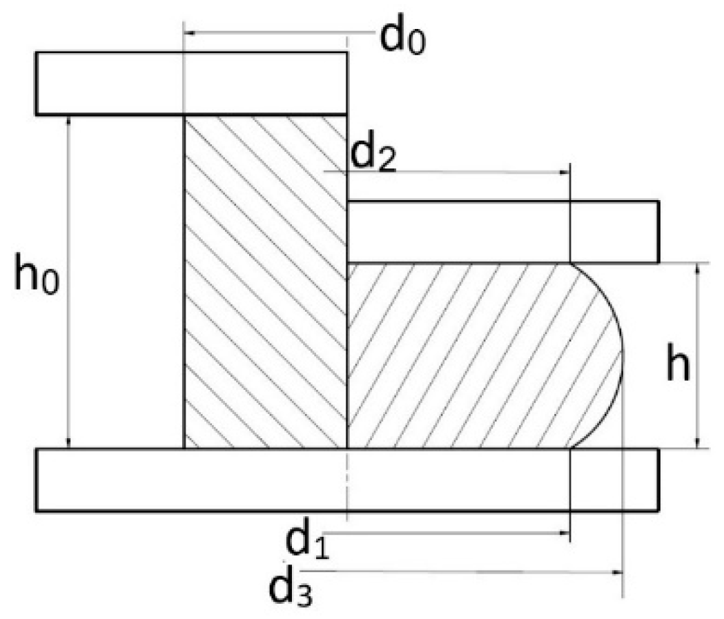
The method, elaborated by S. I. Gubkin consists of measuring the barreling of an upset sample in order to determine the friction coefficient [27]. The test is conducted on a cylindrical sample, which is placed between two flat anvils (Figure 3).
The determination of the friction coefficient is performed based on the geometrical changes in the sample before and after upsetting from the following dependence:
τ = 6.25 δ + 2 δ 2 1 ε d 0 h 0 1.5
where δ—the sample’s barreling, δ = (Dz−Dw)/Dw and ε—relative deformation, ε = Δh/h0
In this method, the friction coefficient increases with changes in the sample’s surface area and when it becomes rough. It should be pointed out that the method is very sensitive to deformation rates. In turn, its positive aspect is the possibility to use the so-called inverse method, which makes it possible to determine the correct material flow curve based on the geometry changes before and after upsetting.

2.4. Cigar Test

This test enables the determination of the friction conditions in the case of low friction coefficient values [26]. For this reason, it has been commonly applied to determine the friction between the surface of a glass panel and a sample made from a soft model in a flat or axisymmetric deformation state. A diagram of the device used for the realization of the test and the shape of the sample are shown in Figure 4.
It is made in the form of boards, whose length is much higher than their width. The upsetting of a sample prepared this way with two parallel undeformable boards causes an increase in its width and length. If the friction coefficient is close to zero, the dimensional changes on the width and length of the sample will be uniform. When the friction reaches higher values, we observe an irregular deformation of the sample. Its center deforms more than its edges, and then it assumes the characteristic shape of a cigar. The changes in the height and width of the sample recorded during the experiment are plotted onto the calibration curves, which makes it possible to determine the friction coefficient of the examined material.

2.5. Test Method for the Process of Extruding Short Objects (Double Cup Extrusion)

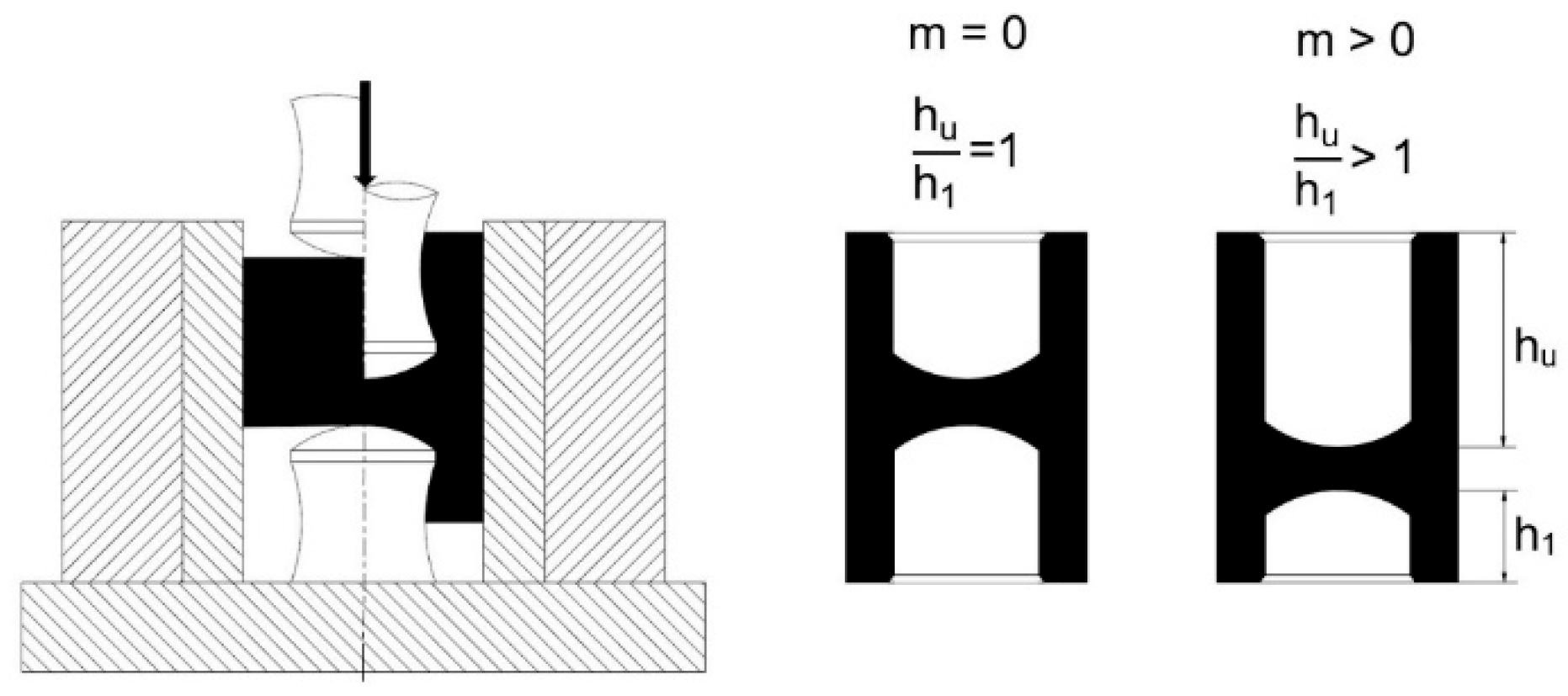
A standard application for the determination of the friction coefficient for short object extrusion processes has been found in the case of the method of the direct–indirect extrusion of cylindrical vessels. In this method, the friction value is determined based on the difference in the height of the upper and lower wall of the extruded vessel [28]. Diagram of the test and the final shape of the product are presented in Figure 5.
The movement of the upper punch in relation to the immovable container and the lower punch causes the material to flow into the gaps between the container and the punches. In the case of a non-friction process or a very low friction, the lower and upper height of the vessel are the same. An increase in friction causes an increase in the height of the upper wall and a decrease in the height of the lower one. Due to the analogy of the process course and the friction conditions present during the direct–indirect extrusion of real materials, the method enables a comparison of the quality of different lubricants as well as an easy selection of the lubricating mixture for the model experiment [29].

2.6. Ring Test Method

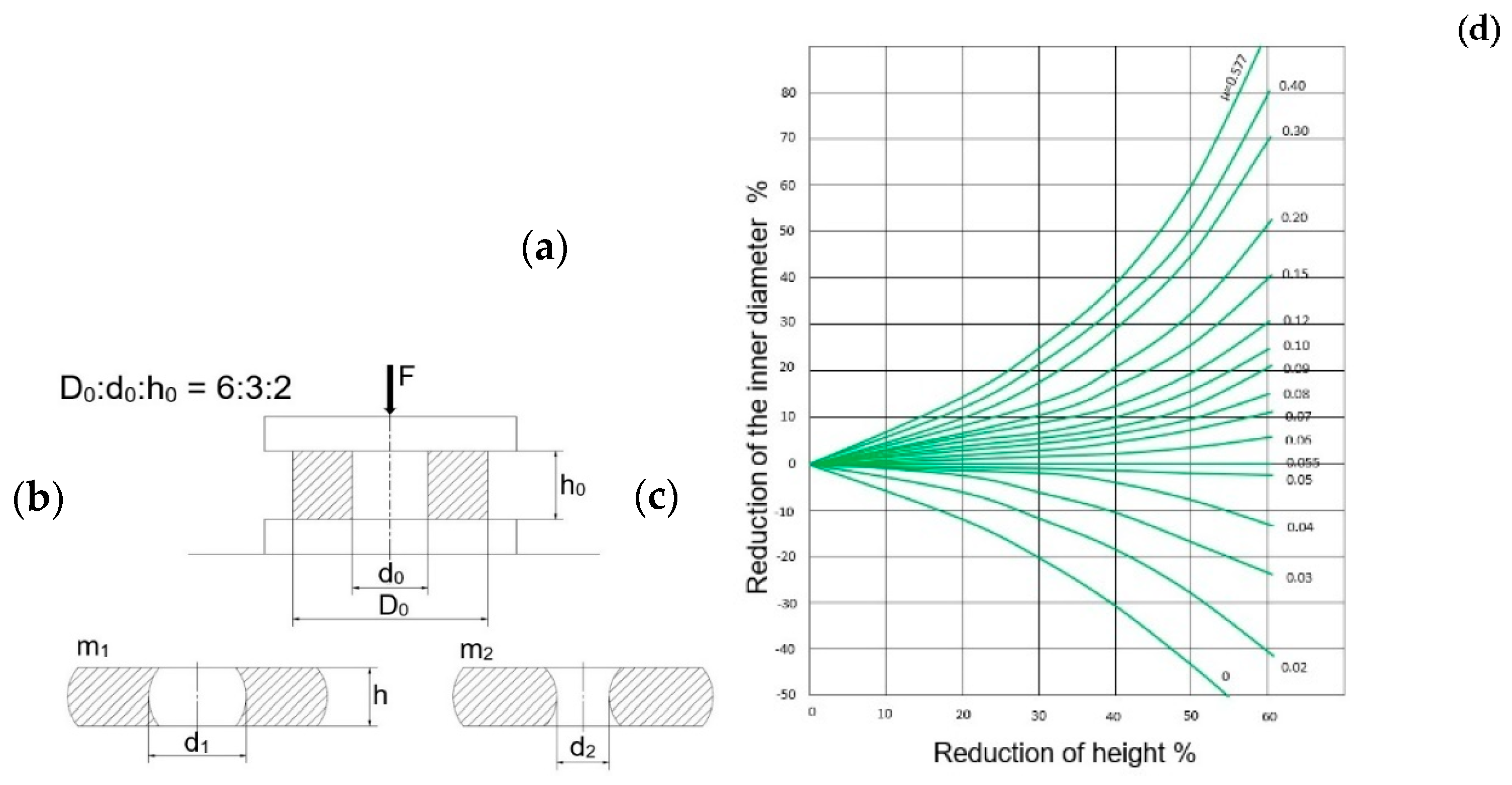
The tests consist of determining the friction coefficient through examinations of samples with the proportions D0:d0:h0 = 6:3:2, where D0—the sample’s external diameter, d0—the sample’s internal diameter, and h0—the sample’s height (Figure 6a).
During the compression of such samples between two parallel non-deformable boards, we observe a change in their dimensions, which is directly connected with the present friction conditions (Figure 6b,c). In the case of high friction forces, on a certain diameter, the material sticks to the tool, and, so, a portion of the material shifts into the inside and a portion into the outside (Figure 6b), with a hindered flow. With lower frictional resistances, the case is reversed (Figure 6c); that is, the internal and external diameters become bigger—a facilitated flow. And, so, in the geometrical aspect, the internal diameter can increase/decrease, or, in an extreme case, it may not change at all. The method is very well suited for comparative examinations of friction under different conditions, e.g., with different lubricants, tool roughnesses, etc. If the knowledge of the friction coefficient value is not needed, it is enough to compare the internal diameters of the rings after upsetting under different conditions, where the initial dimensions of the examined rings and the deformation degree have to be identical. The higher the ring’s internal diameter obtained after upsetting, the lower the observed friction forces. The determination of the numerical values of the friction coefficients consists of comparing the real ring dimensions after upsetting (internal diameter and height) with the theoretical solution, which describes the effect of friction on the shape of the upset ring. For that purpose, proper nomograms and diagrams are used (Figure 6d), from which—for the dimensions h0, d0 and h and d1 or d2—we can read out the friction coefficient value. The test results constitute the guidelines for the selection of the lubricant. The ring test is applied in many cases, for example, in the study [30]. The authors used this method to determine the friction coefficient for magnesium and other light metals and pointed to its advantages as well as possibilities of a simultaneous application of numerical modeling for a better and more accurate determination of friction. Also, in paper [31] the authors realized research of the capabilities at room and hot-forging temperatures (above 1100 °C) of three types of lubricants with two different graphite concentrations. They concluded that the selection of a proper type of lubricant (regarding chemical composition and size of solid suspension) and the graphite concentration are sensitive parameters that influence the results. The test methods collected and presented above refer to the assessment of the tribological conditions present mostly in processes of upsetting, extrusion and hot forging, which are adequate for the industrial process for metals and steel materials. Their character is intermediate, although they still illustrate the industrial conditions much better than in the case of applying tribometers, where the pressures are significantly lower than in forging tests or the described trials to determine the friction coefficient. Few of them enable a fast and simple determination of the friction forces or the lubrication quality conditions. Most of them are experimental methods and not fully verified, which requires the proper instrumentation and special tools. It should also be noted that none of the presented methods consider the heterogeneities of the deformation field, and thus the calculations involve the use of averages values, which, in effect, leads to calculation inaccuracy. Among the methods of friction coefficient determination analyzed and described above, the best and most reliable results, verified in numerous studies and articles, are provided by the ring test, which is predisposed for the analysis of the tribological conditions during hot deformation, as it gives the best results. The use of the results obtained in experimental trials (ring test) enables a fast, cheap and relatively easy selection of the friction conditions and, most of all, the lubricating agents applied in industrial processes. It should be pointed out that the results from the ring test are more accurate and reliable for the industrial process the more the tests are realized in a way that is closest to the given forging process. Additionally, the measurement of the selected geometrical features of the upset samples after the tests, with the use of both classic and modern (3D scanning) measurement techniques, as well as the FEM for the analysis and verification of results, makes it possible to closer approach the industrial conditions and provide a full image as well as a high quality of obtained results. Therefore, conducting ring tests in almost the same conditions as in the industrial forging process ensures the high reliability of the obtained results, which, when introduced into the FEM, enable the correct simulation of tribological conditions, which in turn facilitates a comprehensive analysis of the forging process. And, so, conducting further tests and experiments in the area of applying and improving the ring upsetting method as well as the use of the obtained results to increase the quality and accuracy is fully justified substantively and economically.

3. Test Subject and Methodology

The aim of this study is an analysis of the selected lubricating agents assigned for an industrial process of precision forging on a hydraulic hammer to produce precision forgings in multiple systems: a connecting rod made of carbon steel (16MnCrS5) and a clamping ring for exhaustion systems made of stainless steel (316Ti). For these materials, samples in the form of rings were prepared, and tests under industrial conditions were performed, enabling the determination of the friction coefficients for different lubricants, in order to select the optimal solutions in the aspect of the best lubrication and material flow in the forging process. The research was divided into two main stages. At the first stage, the results of hot ring tests for both materials and the 7 selected dedicated lubricants were presented, and the friction coefficients were determined. The second stage demonstrated the results of ring test numerical simulations for the lowest and highest friction coefficient value determined at the first stage, in order to compare the results obtained under industrial conditions and in a virtual experiment. The following main methods and devices were used in the research:
-
Measurements of temperature changes with a thermal camera (FLIR T540 camera, FLIR Systems, Inc. Wilsonville, OR, USA) and a pyrometer with a type K thermocouple (Testo 850 pyrometer, Testo Poland, Pruszkow, Poland);
-
Scanning forging tools using the 3D scanner (ROMER Absolute ARM 7520si integrated with the scanner RS3 (Hexagon Manufacturing Intelligence, Aarau, Switzerland), together with the Polyworks software 2015);
-
Numerical modeling using Forge 3.0 NxT software (Transvalor, Biot, France);
-
CATIA software (V5R20 program by Dassault, Vélizy-Villacoublay, FRANCE) for designing and supporting engineering works;
-
Other classical measurement and research methods.

3.1. Test Materials

The materials used to prepare the rings for the ring tests were stainless steel 316Ti (1.4571 according to the DIN standard) and carburizing steel 16MnCrS5 (1.7139) in Table 1.
Stainless steel 316Ti is used for the production of forgings constituting elements of silencer clamping rings in motor cars, whereas carburizing steel 16MnCrS5 is applied in the production of connecting rods for petrol sawing machines. The test samples were prepared through a mechanical treatment from round bars with the following dimensions: external diameter—60 mm, internal diameter—30 mm and height—20 mm for stainless steel and external diameter—50 mm, internal diameter—25 mm and height—10 mm for carbon steel (Figure 7), according to the assumptions of the ring test. All samples were made on a Machining Center on a 5-axis Hermle C42U machine. This allowed for an accuracy of ±0.02 mm. In addition, the bases and the internal hole were ground, as these are key features to determine geometric changes.
After the mechanical treatment, a measurement of the key dimensions was made with the use of a digital slide caliper of 0–150 mm, for which the deviations were within the scope of ±0.04 mm. The surface quality of the sample bases was also measured (after grinding) by means of a profilometer SurfTest SJ-210, where the mean roughness for all the samples was 0.63 µm.

3.2. Characteristics of the Selected Lubricants

The following lubricating agents were selected for the tests as lubricants that give the best results during hot forging on hammers. The agents were provided as concentrates, which were then diluted in the proportion 1 to 5.
Lubrodal F185. It is a lubricant produced by Fuchs Lubricants Germany GmbH, which is characterized by excellent separating and releasing properties. Owing to a small addition of graphite, its lubricating properties significantly improve. It exhibits a higher lubricity than conventional lubricants; it increases the durability of the die and ensures much smaller inputs for cleaning compared to regular water–graphite preparations.
Lubrodal C48 PM. It is a lubricating agent for dies used in the warm forging of steel and also in the case of high tool temperatures. It does not contain graphite and demonstrates excellent lubricating, releasing and propelling abilities. After application, it forms a brown adhesive dry coating with high lubricity on the engraved surfaces; it does not contain caustic components, and it does not smoke or burn.
Graphitex CR7. It is a lubricant produced by Tribo Chemie GmbH, mixable with water, for dies, with a very strongly concentrated graphite dispersion. It forms a thin and evenly distributed layer of a lubricating film.
ISOLAT 9550. It is a dense oil lubricant, insoluble in water, to be applied on forging dies. It exhibits high process reliability owing to an exceptionally stable micro-emulsion and excellent adhesive effects.
Lubrodal F318N. It does not contain graphite. It demonstrates excellent releasing and lubricating abilities. It has a good mixability with water and exhibits high wetting and cooling properties; it prevents tool damage and ensures a clean and efficient operation.
Graphitex CR720K. It is a lubricant mixable with water for dies containing graphite, with a wide range of applications. It noticeably improves the material flow during forming and is suitable for the production of forgings from stainless steel.
Lubra hot press 123 HD. It is a lubricating agent produced by LUBRA S.P.A., which is a water-based white mixture. It does not contain graphite. The agent is deposited on the whole die surface, not only on the seats, forming a well-insulating and well-lubricating layer, which burns out during the forging process.

3.3. Description of the Ring Test Procedure

In order to determine the friction coefficient and provide the best results, the ring test was applied, consisting of upsetting samples between two flat boards. The main advantage of this method is that the friction coefficient is determined only based on the measurements of sample geometry. It is not necessary to know the mechanical properties of the deformed material and there is no necessity to measure the force parameters of the process, which fundamentally distinguishes this method and its simplicity. The ring tests were carried out under industrial conditions, after a previous preparation of the selected lubricants in proper proportions (1:5; concentrate—liquid), as well as after the heating of the samples to the forging temperature—about 1200C—and also after the heating of the flat forging dies (Figure 8).
The upsetting tests were conducted on a hydraulic hammer Lasco HO-U 160 with a blow energy of 16 kJ and with the use of an electric resistance furnace, in which the samples were heated to 1200 °C for about 10 min. The dies were made in the form of simple blocks with the dimensions 400 mm × 150 mm × 150 mm. The flat surface was ground and it was where the samples were subjected to upsetting. The temperature of the lower die equaled 89 °C and that of the upper die equaled 108 °C, before the tests began.
The measured temperature (measured using a thermovison camera) of the particular rings was at the level 1179–1198 °C (Figure 9). The samples were upset between flat anvils, by way of depositing the particular lubricants with aerosol. Next, they were upset with a hammer energy of 20% and 50% to about half of the initial height.

4. Results

After the performed ring upsetting tests, measurements of the internal diameters and heights were made, and, next, after the recalculations from the nomogram (Figure 6d), the friction coefficients were determined for the particular samples and the applied lubricants dedicated to hot forging processes. For each variant, two repetitions were carried out. According to the ring test’s principle, for the friction coefficient determination, it is necessary to calculate the change in the sample’s height and external diameter. The mean diameters were calculated as the arithmetic average from three measurements: of the diameters at the front surfaces and in the middle of the sample’s height. In turn, in the case of a change in the sample’s height, two measurements were made. It should be noted that the samples after the tests were not always symmetrical, and the internal and external diameters had a partially irregular shape, sometimes elliptical, and, so, in such cases, the average value for the internal diameter was determined.

4.1. Results of Friction Coefficient Determination

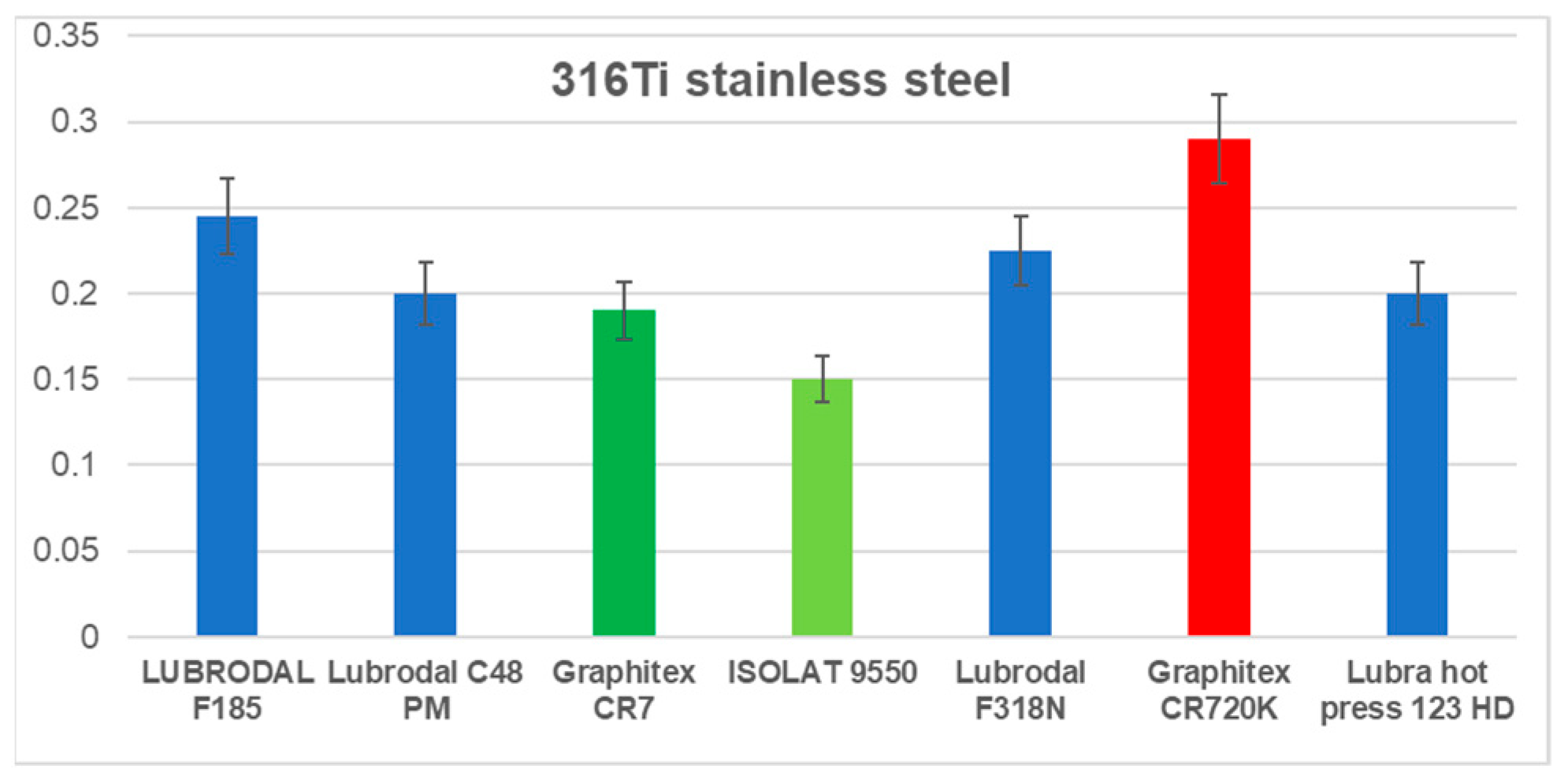
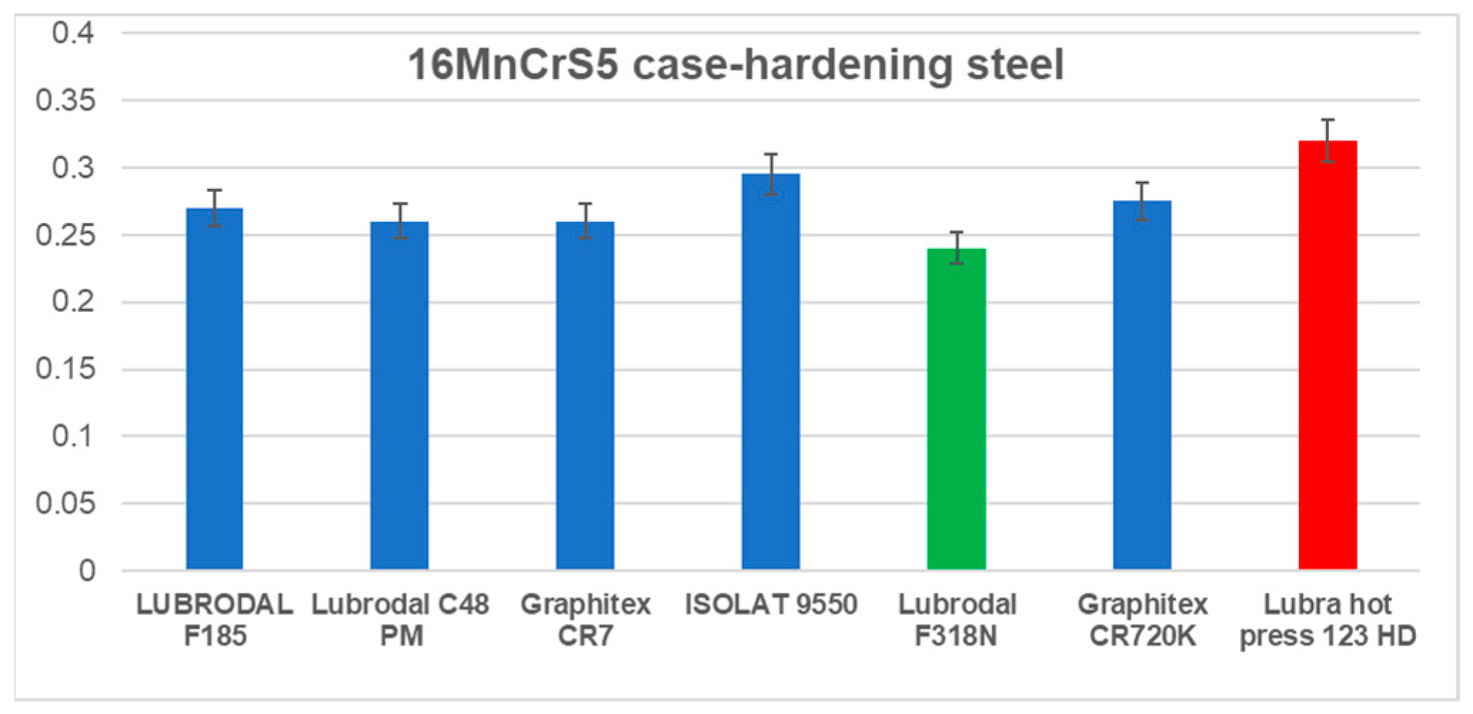
The obtained results with the friction coefficients determined based on the ring test are shown in Figure 10 (stainless steel) and Figure 11 (carbon steel).
They demonstrate that the most advantageous friction coefficient for stainless steel was reached by the lubricant ISOLAT 9550 (µ = 0.15). In turn, the preliminary forging tests showed that this lubricant, due to the presence of oil in it, causes the sticking of the forgings as well as a large amount of smokiness (oil burning), which makes it impossible to use in production.
Another lubricating agent, with a better friction coefficient, is Graphitex CR 7 (µ = 0.19). The worst results in the aspect of the friction coefficient were obtained for Graphitex CR720K (µ = 0.29).
For the carburizing steel samples, the differences in the friction coefficient are insignificant. The highest friction coefficient was achieved for the lubricants Lubra hot press 123HD (µ = 0.32) and and ISOLAT 9550(µ = 0.29), whereas the lowest values were obtained for Lubrodal F318N (µ = 0.24) and Graphitex CR 7 (µ = 0.26).

4.2. Results of 3D Scanning

Additionally, for a more thorough analysis of the geometrical changes in the samples during the examinations in a ring test, measurements with the use of 3D scanning were made, and the obtained results were referred to the nominal (a disk before the upsetting test). The obtained results for the highest and lowest friction coefficient values for both materials (for stainless steel, Isolatu was replaced with Graphitex CR 7), in the form of a color map of deviations in the nominal directions to the surface (for the sample at the mid-height of the disk), are presented in Figure 12.
In the case of the ring test (Figure 12a) for which Lubrdal F185 (µ = 0.24) was used as the lubricant, the internal diameter after upsetting decreased from 25.04 mm to the average diameter of 16.4 mm, that is, by about 8.6 mm, which, as shown by the scanning results, is confirmed because inside the ring a material growth from +4.31 to +4.34 mm can be observed. Similarly, in the case of the sample for which the applied lubricating agent was Lubra hot press 123HD (u = 0.33), the internal diameter after upsetting decreased from 25.14 mm to the mean diameter of 15.5 mm, that is, by about 9.64 mm, which is confirmed by the scanning results (an average of +4.82 mm). Similarly, in the case of the results obtained for stainless steel, for the extreme friction coefficient values, for the sample with Graphitex CR 7 (u = 0.19) as the lubricant, the internal diameter after upsetting decreased from 30.03 mm to the average diameter of 22.7 mm, that is, by about 7.34 mm, which is confirmed by the scanning results (an average of +3.7 mm). Also, in the case of the sample (Figure 12d) for which the applied lubricating agent was Lubra hot press 123HD (u = 0.33), the internal diameter after upsetting decreased from 30.04 mm to the average diameter of 20.1 mm, that is, by about 9.64 mm, which is confirmed by the scanning results (an average of +4.97 mm).

4.3. Results of Numerical Modeling of a Ring Upsetting Test

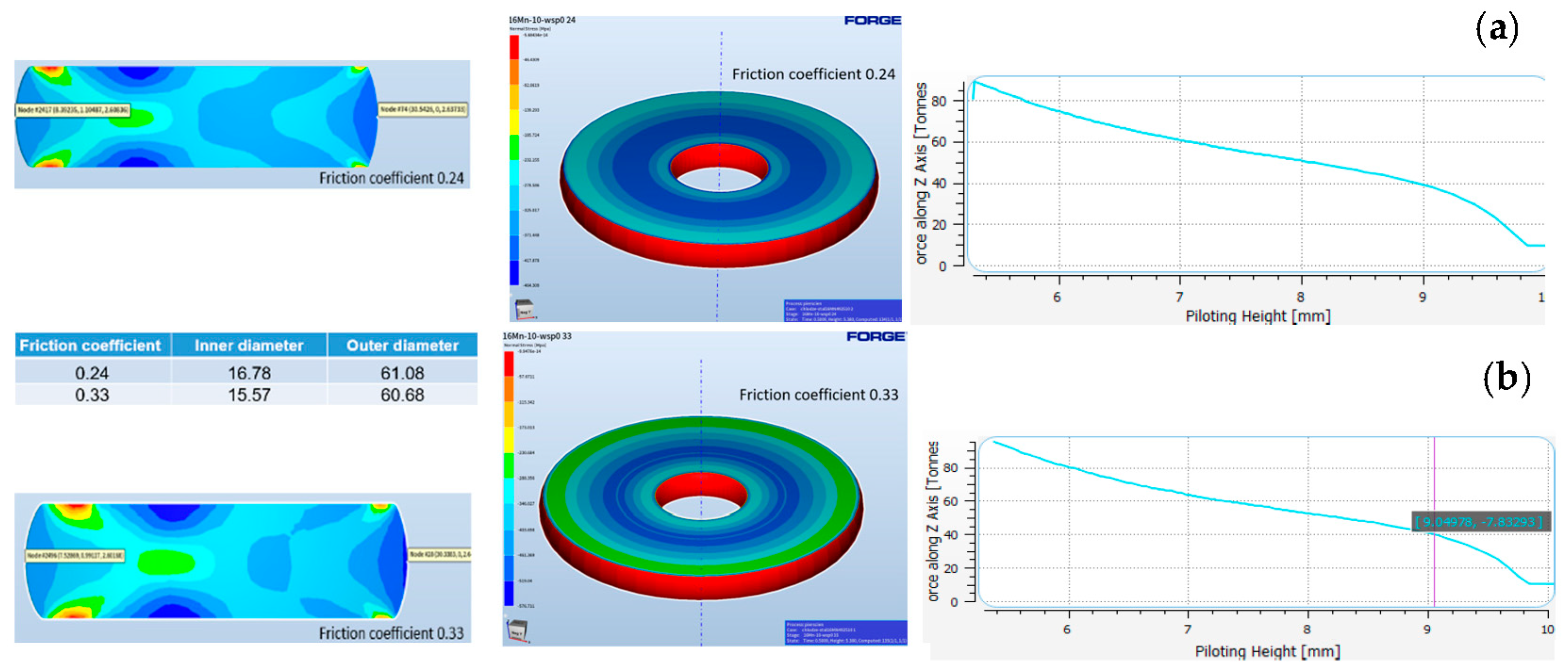
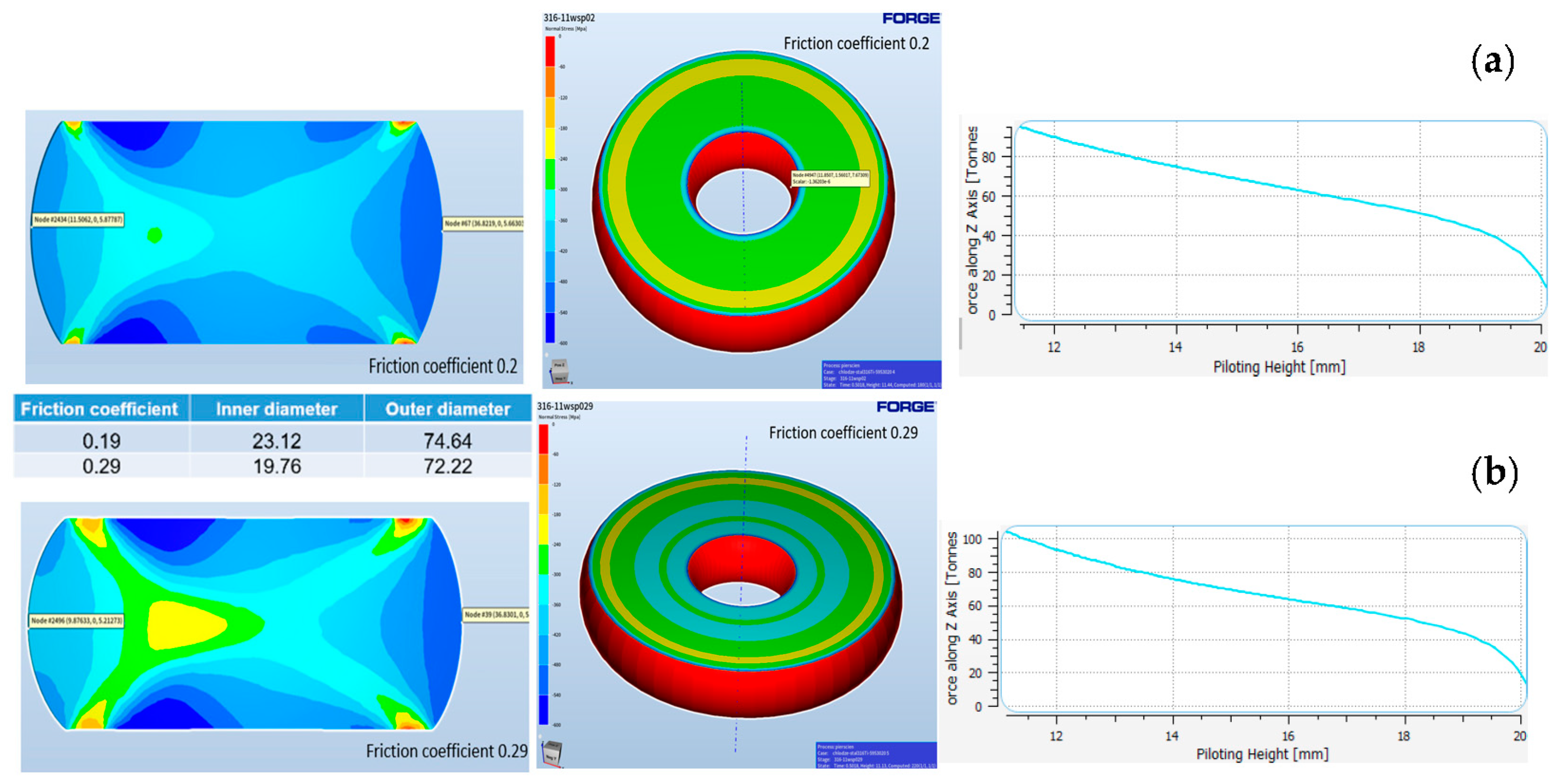
The following stage of research was modeling with the purpose to analyze the obtained results and the correctness and agreement of the friction coefficients determined in the ring test based on the geometrical changes in the upsetting tests of a ring for the extreme variants of the determined friction coefficients for both materials. In the Forge 3.0nxt software, it is possible to apply two basic friction models: the Coulomb model, described with Equation (1), and the constant friction model (also called the Tresca model), described with Equation (2). The third available model is a combination of the two mentioned above. In the research, it was this friction model that was applied, through numerous simulations aiming at finding friction coefficient values for which we can achieve the best agreement between the theoretical and experimental sample dimensions. Figure 13 presents the simulation results with the plastic deformation distributions on cross-sections for samples after upsetting together with the force courses for carbon steel, and Figure 14 shows results for stainless steel The change in the sought coefficients was introduced based on the principle saying that higher values of friction coefficient or friction factor reduce the theoretical external and internal diameters of the rings near the anvils.
The upsetting conditions connected with the kinematics of the tool’s movement were assumed according to the characteristics of a hammer with a maximal blow energy of 16 kJ. The initial conditions referring to the initial sample temperature and tool temperature for the particular trials were assumed base on industrial conditions. The samples, in the form of rings, were digitized with TET4 elements in the numbers of 1658 (for carbon steel) and 2328 (for stainless steel). The tools (flat anvils) were assumed to be rigid, with a heat exchange. The following heat exchange conditions in the contact were selected: steel-steel at 30 N/s/mm/°C and with the environment 0.25 N/s/mm/°C, which made it possible to obtain a similar FEM geometry to the case of the samples after the ring test. On the basis of the displacement values of selected points, we can determine the changes in the internal and external diameters for the extreme friction coefficient values. The obtained results referring to the deformation distributions (left column in Figure 13 and Figure 14) show a bigger localization of deformation in the case of samples deformed with higher friction coefficient values in the areas where the base transitions into a barrel—this is more visible for stainless steel samples.
The analysis of the surface pressure distributions (middle column in Figure 13 and Figure 14) demonstrated that they are higher for the carbon steel material in comparison to stainless steel, which can result from the different sample sizes and the different hammer energies used in the upsetting. In turn, it is difficult to find significant differences in the case of different values of the assumed friction coefficient for the same material. In the examination of the force courses during upsetting, we can notice that for higher friction coefficient values for other materials the forces are much higher than the forces obtained for the assumed lower friction coefficient values (right column in Figure 13 and Figure 14). In turn, the obtained simulation results show that the dimensions achieved in the FEM, especially those of the internal and external diameters, were similar to the dimensions of samples after the ring upsetting for both materials (Figure 13 and Figure 14). The slight differences can result from, e.g., the non-uniform temperature distribution during the experimental tests the effect of the deposition of the lubricant layer and the duration of the particular trial (a fast heat exchange between the samples and the tools and the environment as well as the lubricant, that is, the generally understood conditions for the realization of the ring tests in respect of the “ideal” conditions in numerical simulations, etc.). It should be emphasized that the results obtained from the FEM, in respect of the deformation, pressure and upsetting force distributions and most of all the geometrical changes, point to a good agreement with the results obtained during tests under industrial conditions. Thereby, it confirms the possibility of aiding the experiment with IT tools, such as numerical modeling, with the assumption of a good knowledge of the software itself and also the knowledge and experience of the scientists/engineers-technologists in the interpretation of the FEM results. And, so, such an approach makes it possible to verify and select the initial-boundary conditions in numerical modeling during simulations of ring tests for the determination of the friction conditions.

5. Summary and Conclusions

This study performed a review and analysis of the most popular methods of determining the friction coefficient in the aspect of the effect of the applied lubricating agents in order to select the optimal tribological conditions. The conducted analysis has demonstrated that the most commonly used method, owing to its simplicity, facility of realization, interpretation of results and, most of all, the reliability of the obtained results in the context of their use in the industrial forging processes, is the ring test. The ring upsetting tests were carried out on a hydraulic hammer for conditions similar to those present in the industrial forging process (the same working temperatures of the tools and the deformed material, the same deformation rates and applied hammer energy, the same lubricant application), and the characteristic geometrical features as well as the friction coefficients were determined. The obtained results have shown the following:
-
For carbon steel, the lowest value was achieved for the lubricant Lubrodal F185 (µ = 0.24) and the highest for Lubr_hot_press 123HD (µ = 0.32). Small differences were observed for this material in the value of friction in comparison to samples made from stainless steel (316Ti).
-
For stainless steel, the lowest value was obtained for Graphitex CR 7 (µ = 0.19). The highest friction coefficient was reached for the lubricant Graphitex CR720K (µ = 0.29).
-
It should be noted that the samples after the upsetting tests were not always symmetrical, and the internal and external diameters had a partially irregular shape, sometimes an elliptical one, and, so, in such cases, the average value of the internal diameter was determined. This can have an effect on the accuracy of the friction coefficient determination.
-
Measurements were made of the geometrical changes with the use of 3D scanning for the extreme friction coefficient values, and the obtained data confirmed the results achieved from the measurements by means of a digital slide caliper and thus also the correctness of the determined friction coefficient values.
-
The numerical simulations performed in the Forge 3.0 NxT program confirmed the possibility of obtaining a high agreement between the FEM and experimental tests, as modeling provides reliable information on the geometrical changes and plastic deformations and can constitute a support for the experiment through the use of IT tools, especially numerical modeling, for a more thorough analysis of the tribological conditions in industrial forging processes.
-
The key aspect of correct FE modeling is the proper determination of friction coefficients (test conditions very close to industrial) and also the right choice of the technological parameters and the heat transfer coefficients as well as others, along with knowledge and experience in the interpretation of the FEM results.
-
The directions of further research will be focused on a complex and long-term analysis of the lubricants selected in the conducted ring tests, which are used in the industrial processes of producing forgings from stainless steel and carbon steel, in the context of not only the lowest friction coefficient value but also other features and properties, which should be exhibited by the optimal lubricating agent.

Author Contributions

Conceptualization, Ł.D., M.H. and J.Z.; methodology, M.H., J.M. and T.S.; software, S.P.; validation, J.M., J.Z. and A.M.; formal analysis, M.H. and Ł.D.; investigation, J.M. and J.Z.; resources, A.M.; data curation, Ł.D. and J.M.; writing—original draft preparation, M.H. and T.S.; writing—review and editing, M.H., Ł.D. and J.M.; visualization, J.M. and J.Z.; supervision, M.H.; project administration, Ł.D. All authors have read and agreed to the published version of the manuscript.

Funding

This research received no external funding.

Data Availability Statement

Not applicable.

Conflicts of Interest

The authors declare no conflict of interest. The funders had no role in the design of this study; in the collection, analyses or interpretation of data; in the writing of this manuscript; or in the decision to publish the results.

References

  1. Joun, M.S.; Moon, H.G.; Choi, I.S.; Lee, M.C.; Jun, B.Y. Effects of Friction Laws on Metal Forming Processes. Tribol. Int. 2009, 42, 311–319. [Google Scholar] [CrossRef]
  2. Bay, N.; Olsen, D.; Wibom, O.; Martins, P. Classification of Tribology Tests for Bulk Metal Forming; Personal Communications; Danish Technical University: Lyngby, Denmark, 2004. [Google Scholar]
  3. Male, A.T.; Cockcroft, M.G. A Method for the Determination of the Coefficient of Friction of Metals under Conditions of Bulk Plastic Deformation. Wear 1966, 9, 241. [Google Scholar] [CrossRef]
  4. Sigvant, M.; Pilthammar, J.; Hol, J.; Wiebenga, J.H.; Chezan, T.; Carleer, B.; van den Boogaard, T. Friction in sheet metal forming: Influence of surface roughness and strain rate on sheet metal forming simulation results. Procedia Manuf. 2019, 29, 512–519. [Google Scholar] [CrossRef]
  5. Stembalski, M.; Preś, P.; Skoczyński, W. Determination of the friction coefficient as a function of sliding speed and normal pressure for steel C45 and steel 40HM. Arch. Civ. Mech. Eng. 2013, 13, 444–448. [Google Scholar] [CrossRef]
  6. Ramaraj, T.C.; Shaw, M.C. A New Method of Evaluating Metal-Working Lubricants. J. Tribol. 1985, 107, 216–219. [Google Scholar] [CrossRef]
  7. Arentoft, M.; Bay, N.; Tang, P.T.; Jensen, J.D. A New Lubricant Carrier for Metal Forming. CIRP Ann. 2009, 58, 243–246. [Google Scholar] [CrossRef]
  8. Polcar, T.; Novák, R.; Široký, P. The Tribological Characteristics of TiCN Coating at Elevated Temperatures. Wear 2006, 260, 40–49. [Google Scholar] [CrossRef]
  9. Kubart, T.; Polcar, T.; Kopecký, L.; Novák, R.; Nováková, D. Temperature Dependence of Tribological Properties of MoS2 and MoSe2 Coatings. Surf. Coat. Technol. 2005, 193, 230–233. [Google Scholar] [CrossRef]
  10. Ludema, K.C. Mechanism-Based Modeling of Friction and Wear. Wear 1996, 200, 1–7. [Google Scholar] [CrossRef]
  11. Hawryluk, M.; Dudkiewicz, Ł.; Marzec, J.; Rychlik, M.; Tkocz, R. Selected aspects of lubrication in die forging processes at elevated temperatures—A review. Lubricants 2023, 11, 206. [Google Scholar] [CrossRef]
  12. Wu, Y.; Recklin, V.; Groche, P. Strain Induced Surface Change in Sheet Metal Forming: Numerical Prediction, Influence on Friction and Tool Wear. J. Manuf. Mater. Process. 2021, 5, 29. [Google Scholar] [CrossRef]
  13. Jeswiet, J.; Wild, P. Sensing friction: Methods and devices. J. Form. Process. 2001, 4, 125–134. [Google Scholar] [CrossRef]
  14. Sofuoglu, H.; Gedikli, H. Determination of Friction Coefficient Encountered in Large Deformation Processes. Tribol. Int. 2002, 35, 27–34. [Google Scholar] [CrossRef]
  15. Sofuoglu, H.; Gedikli, H.; Rasty, J. Determination of Friction Coefficient by Employing the Ring Compression Test. J. Eng. Mater. Technol. 2001, 123, 338–348. [Google Scholar] [CrossRef]
  16. Menezes, P.L.; Kumar, K.; Kishore; Kailas, S.V. Influence of Friction during Forming Processes—A Study Using a Numerical Simulation Technique. Int. J. Adv. Manuf. Technol. 2009, 40, 1067–1076. [Google Scholar] [CrossRef]
  17. Ramezani, M.; Ripin, Z.M. A Friction Model for Dry Contacts during Metal-Forming Processes. Int. J. Adv. Manuf. Technol. 2010, 51, 93–102. [Google Scholar] [CrossRef]
  18. Bucholz, E.W.; Kong, C.S.; Marchman, K.R.; Sawyer, W.G.; Phillpot, S.R.; Sinnott, S.B.; Rajan, K. Data-Driven Model for Estimation of Friction Coefficient Via Informatics Methods. Tribol. Lett. 2012, 47, 211–221. [Google Scholar] [CrossRef]
  19. Zhou, C.; Hu, B.; Qian, X.; Han, X. A Novel Prediction Method for Gear Friction Coefficients Based on a Computational Inverse Technique. Tribol. Int. 2018, 127, 200–208. [Google Scholar] [CrossRef]
  20. Weinmann, K.J.; Bhonsle, S.R.; Gerstenberger, J. On the Determination of the Coefficient of Friction and the Friction Factor by the Strip-Tension Friction Test. CIRP Ann. 1990, 39, 263–266. [Google Scholar] [CrossRef]
  21. Storchak, M.; Möhring, H.-C.; Stehle, T. Improving the Friction Model for the Simulation of Cutting Processes. Tribol. Int. 2022, 167, 107376. [Google Scholar] [CrossRef]
  22. Han, H. Determination of Mean Flow Stress and Friction Coefficient by the Modified Two-Specimen Method in Cold Rolling. J. Mater. Process. Technol. 2005, 159, 401–408. [Google Scholar] [CrossRef]
  23. Szarapin, E.F.; Maksimov, N.V. Primenenie Osadki Klinovidnych Obrazcov Dlja Opredelelenija Koefficenta Trenija. Izv. VUZ Cern. Metall. 1963. [Google Scholar]
  24. Dilmec, M.; Arap, M. Effect of Geometrical and Process Parameters on Coefficient of Friction in Deep Drawing Process at the Flange and the Radius Regions. Int. J. Adv. Manuf. Technol. 2016, 86, 747–759. [Google Scholar] [CrossRef]
  25. Halaunbrenner, M. Directional Effects in Friction. Wear 1960, 3, 421–425. [Google Scholar] [CrossRef]
  26. Fricker, D.C.; Wanheim, T. Low Friction Coefficient Estimation for Model Material Experiments. Wear 1974, 27, 303–317. [Google Scholar] [CrossRef]
  27. Siebel, E.; Pomp, A. Further Development of the Compression Test. Mitt. Kaiser–Wilhelm-Inst. Eisenforsch. 1928, 10, 55–62. (In German) [Google Scholar]
  28. Schrader, T.; Shirgaokar, M.; Altan, T. A Critical Evaluation of the Double Cup Extrusion Test for Selection of Cold Forging Lubricants. J. Mater. Process. Technol. 2007, 189, 36–44. [Google Scholar] [CrossRef]
  29. Bulzak, T.; Tomczak, J.; Pater, Z. A Comparative Analysis of Hot and Cold Flashless Forging of a Stepped Shaft Using Vertically-Parted Dies. Int. J. Adv. Manuf. Technol. 2021, 116, 2521–2530. [Google Scholar] [CrossRef]
  30. Gontarz, A.; Dziubińska, A.; Okoń, Ł. Determination of friction coefficients at elevated temperatures for some Al, Mg and Ti alloys. Arch. Metall. Mater. 2011, 56, 379–384. [Google Scholar] [CrossRef]
  31. Sánchez Egea, A.J.; Martynenko, V.; Abate, G.; Deferrari, N.; Martinez Krahmer, D.; López de Lacalle, L.N. Friction capabilities of graphite-based lubricants at room and over 1400 K temperatures. Int. J. Adv. Manuf. Technol. 2019, 102, 1623–1633. [Google Scholar] [CrossRef]
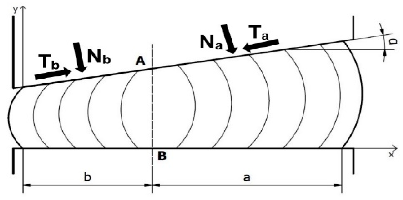
Figure 1. Process of upsetting a wedge sample with plotted vertical lines.
Lubricants 11 00399 g001
Figure 2. Upsetting process of the conical sample.
Lubricants 11 00399 g002
Figure 3. Process of upsetting a cylindrical sample.
Lubricants 11 00399 g003
Figure 4. Diagram of a device used in the process of compressing a sample in a cigar test: 1—sample; 2 and 3—acrylic separators; 4 and 5—steel boards; 6 and 7—sample length measurement sensors; 8, 9 and 10—tips of the sample length measurement sensors.
Lubricants 11 00399 g004
Figure 5. Double Cup Extrusion -process of forward-backward extrusion.
Lubricants 11 00399 g005
Figure 6. View of (a) a diagram of the ring upsetting process and the dimensions of samples after upsetting for different friction coefficient values, (b) poor lubrication d1 > d0, (c) good lubrication 8d2 < d0, m2 > m1, and (d) nomogram for friction coefficient readings.
Lubricants 11 00399 g006
Figure 7. Pre-processed test samples: (a) during preparation from stainless steel, (b) after a complex mechanical treatment, (c) sets of ready samples from both materials.
Lubricants 11 00399 g007
Figure 8. Photographs of (a) the manner of lubricant preparation and (b) the technological trials.
Lubricants 11 00399 g008
Figure 9. Photographs of (a) the temperature measurements of the upper and lower tools with the use of a pyrometer and thermocouples, (b) the thermograms with the temperature distributions right before the tests and (c) the upset samples after the tests for stainless steel and carbon steel.
Lubricants 11 00399 g009
Figure 10. Results of the friction coefficient determination from a ring test for stainless steel.
Lubricants 11 00399 g010
Figure 11. Results of the friction coefficient determination from a ring test for carbon steel.
Lubricants 11 00399 g011
Figure 12. Three-dimensional scanning results for (a) a carbon steel sample, for which Lubrodal F318N was used (u = 0.24), (b) a sample with lubrication by means of Lubra hot press 123HD (u = 0.33), (c) a stainless steel sample for which Graphitex CR 7 was applied (u = 0.19) and (d) a sample with lubrication by means of Graphitex CR720K (u = 0.29).
Lubricants 11 00399 g012
Figure 13. Simulation results with the distributions of deformations, unit pressures and forces during upsetting for carbon steel for the extreme friction coefficient values and the internal and external diameter dimensions for (a) u = 0.24 and (b) u = 0.33.
Lubricants 11 00399 g013
Figure 14. Simulation results with the distributions of deformations, unit pressures and forces during upsetting for stainless steel for the extreme friction coefficient values and the internal and external diameter dimensions for (a) u = 0.2 and (b) u = 0.29.
Lubricants 11 00399 g014
Table 1. Chemical compositions of steel 316 Ti and steel 16MnCrS5.
CSiMnPSCrVNiWMoNiTi
316 Ti0000016.5 2.010.50Min.
0.081.02.00.0450.01518.5 2.513.50.70Max.
16MnCrS50.140.171.00000.80000 Min.
0.190.371.300.0350.0351.10<0.050.30.2 Max.
Disclaimer/Publisher’s Note: The statements, opinions and data contained in all publications are solely those of the individual author(s) and contributor(s) and not of MDPI and/or the editor(s). MDPI and/or the editor(s) disclaim responsibility for any injury to people or property resulting from any ideas, methods, instructions or products referred to in the content.