Lubricant-Free Thermoforming Mold Using Pulse Electrochemical Polishing


Abstract
:
1. Introduction
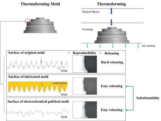
1.1. Thermoforming
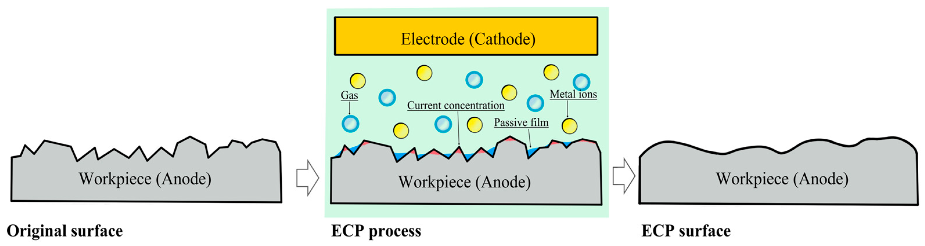
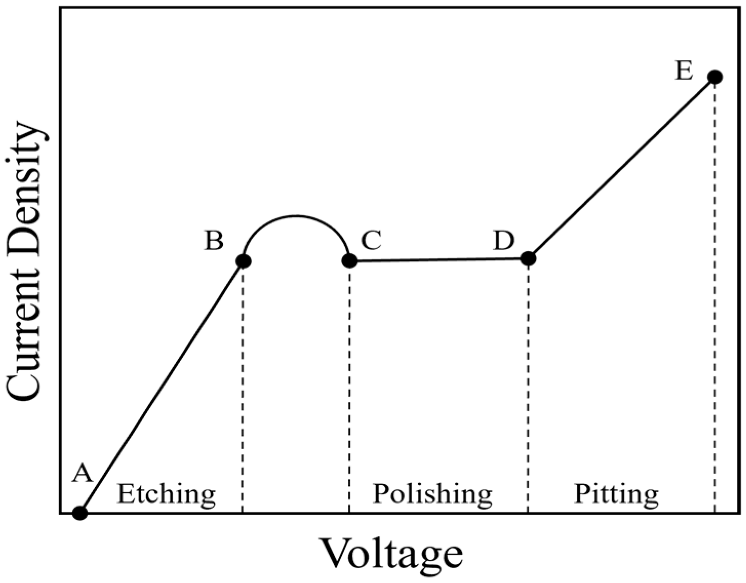
1.2. Electrochemical Polishing
1.3. Literature Review
2. Experimental Setup
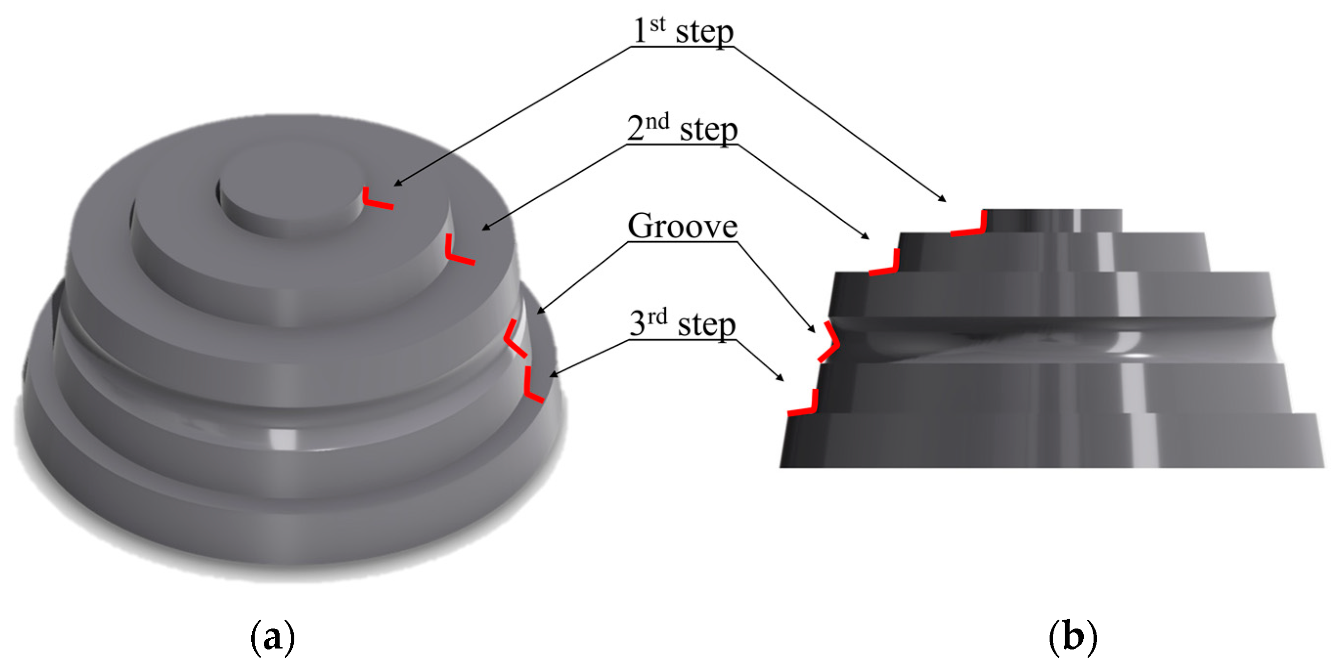
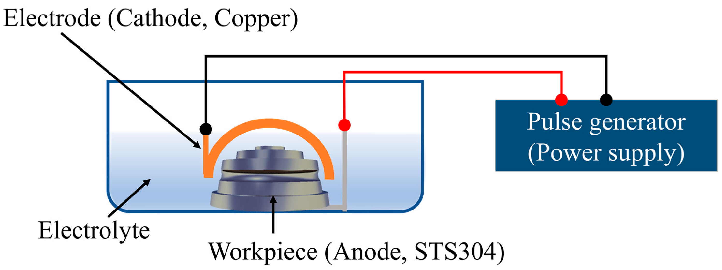
2.1. PECP Process for the TF Mold
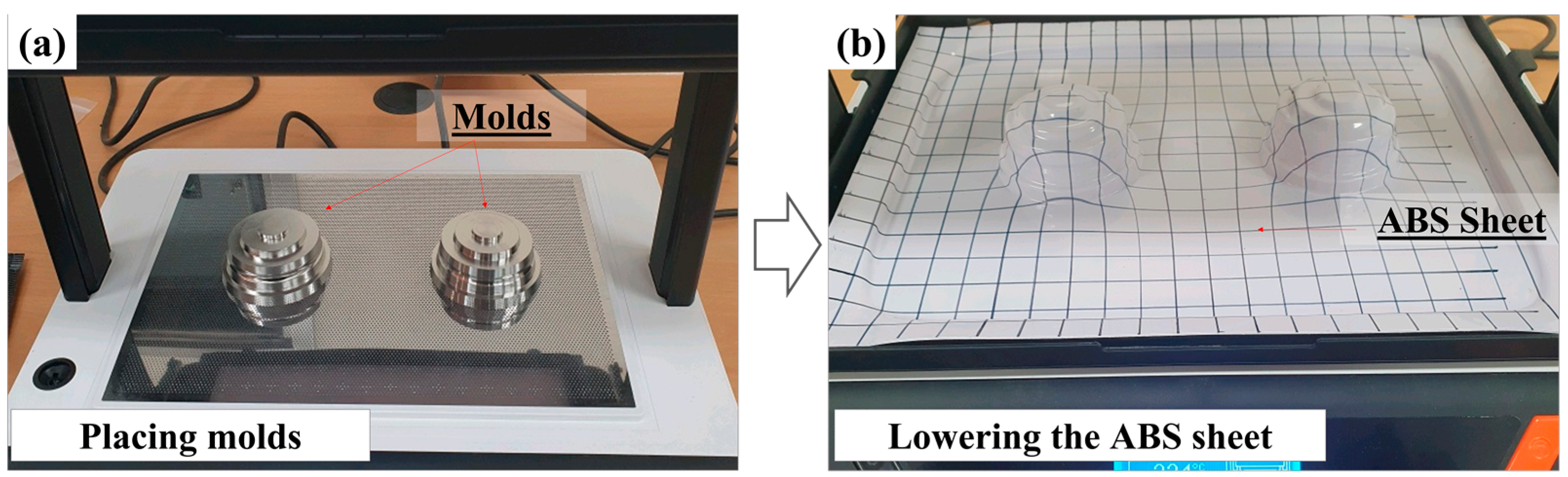
2.2. TF and Analysis of Shape Reproducibility
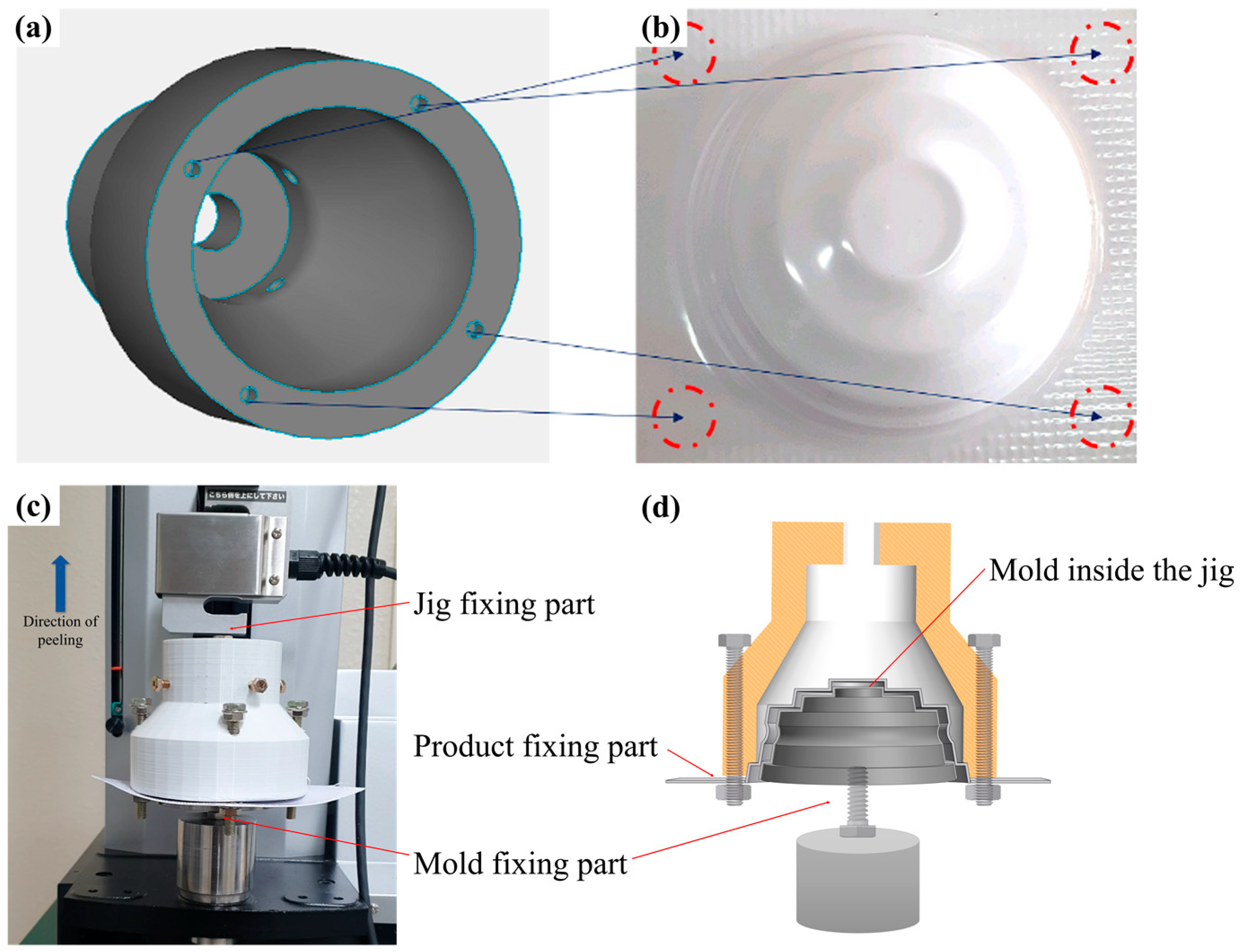
2.3. Peeling Test
2.4. Measurement of Product Surface Morphology Using AFM and Tribological Characterization Using LFM Mode
3. Results
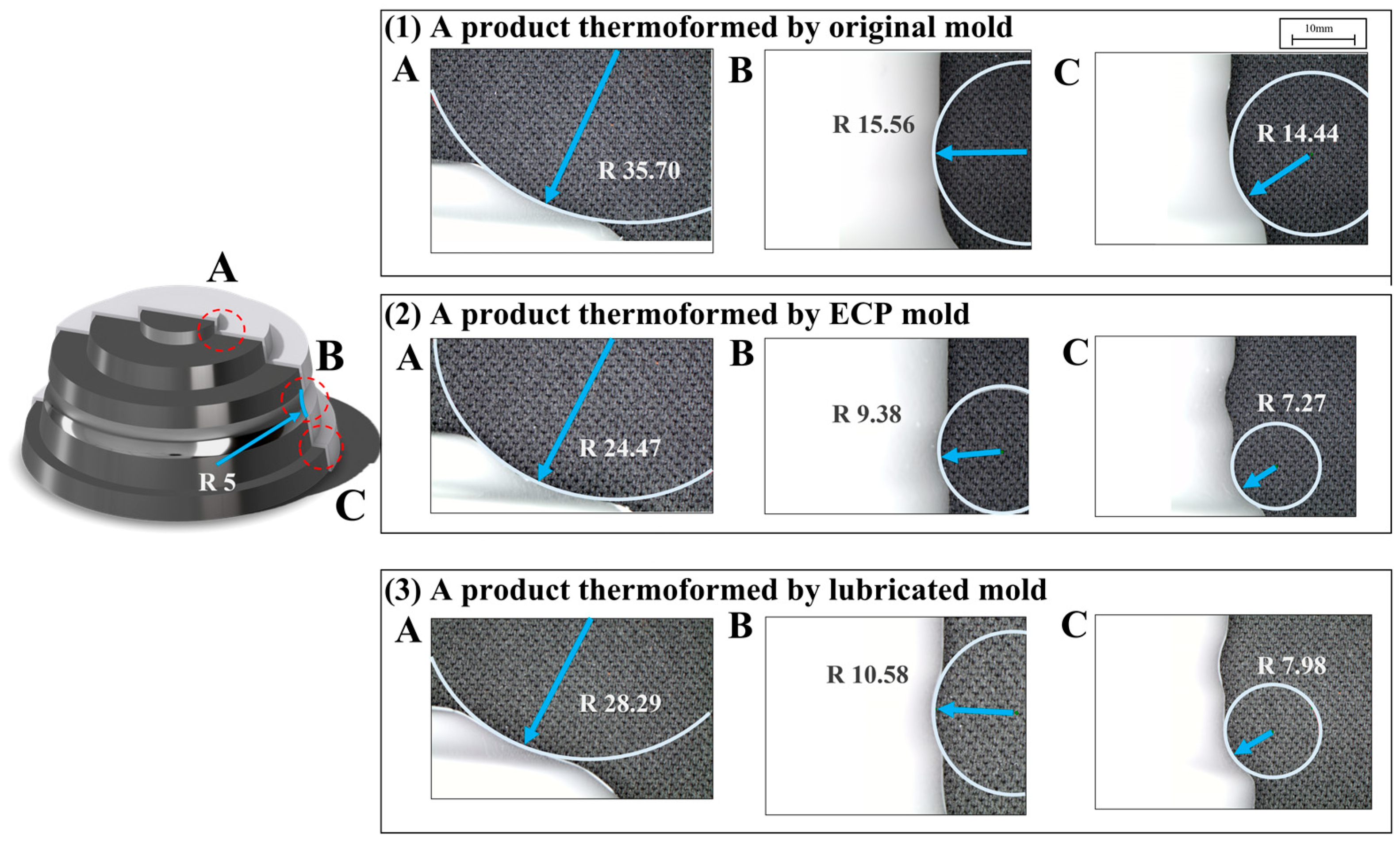
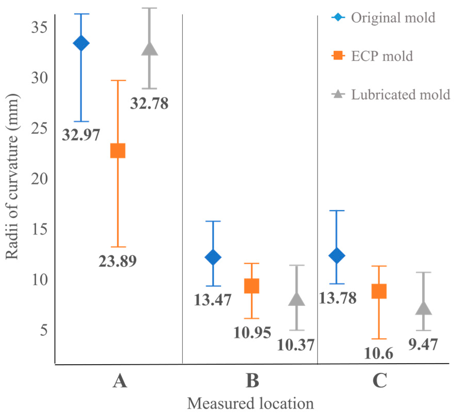
3.1. Comparative Analysis of the Reproducibility of Thermoformed Products in Different Types of Molds
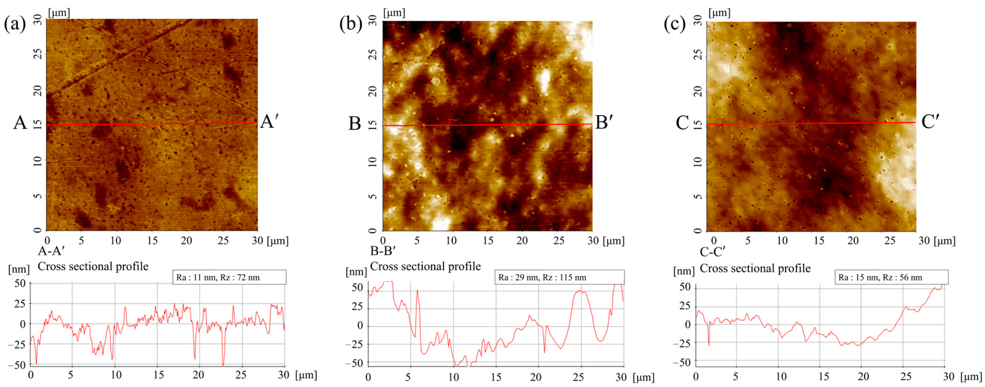
3.2. Analyzing the Impact of Mold Surface Quality on the Surface of Thermoformed Products
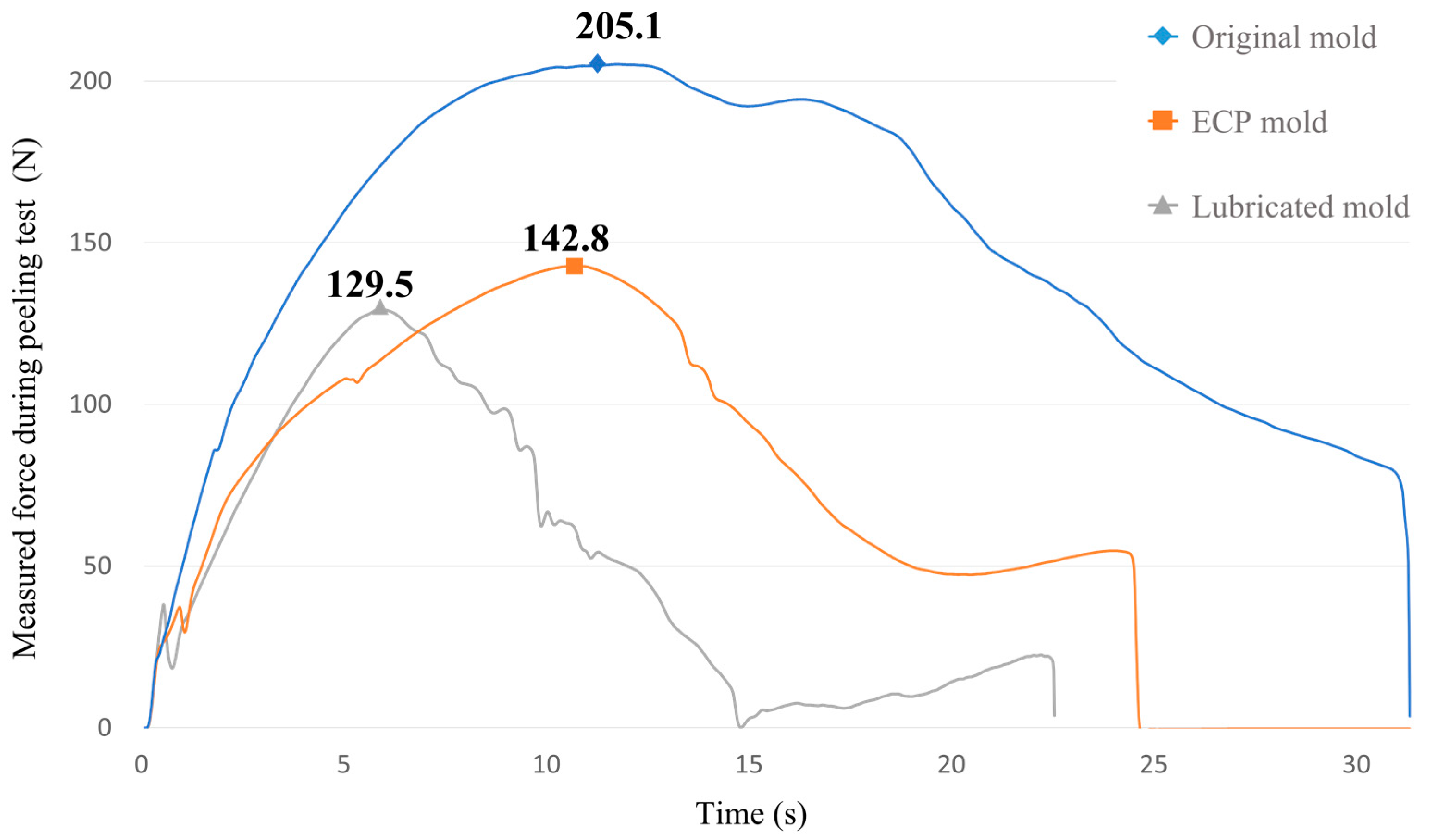
3.3. Peeling Test Results
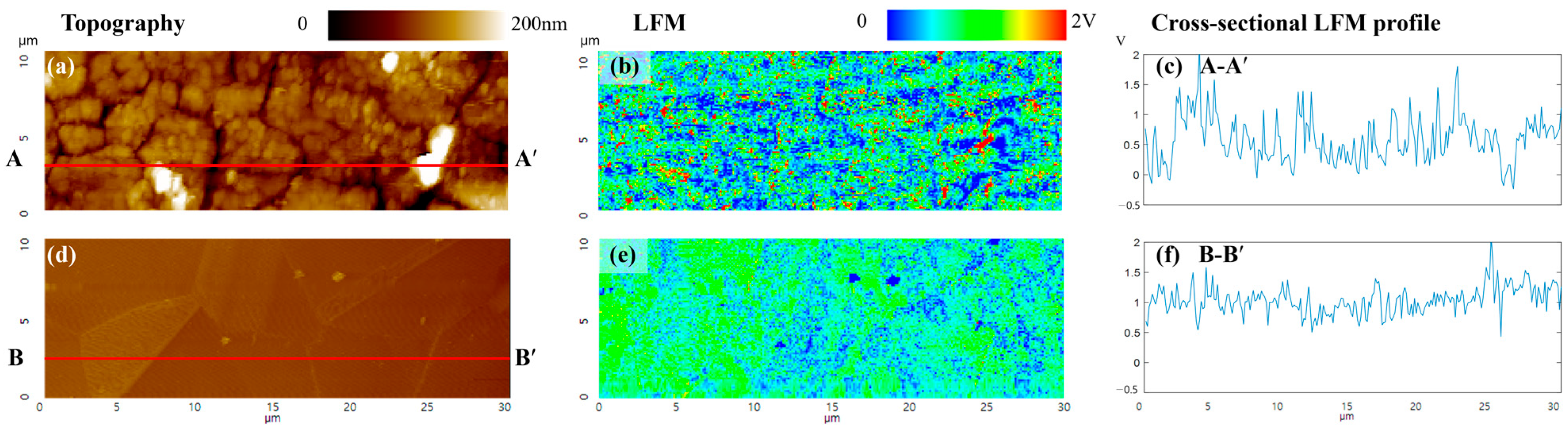
3.4. Analysis of Friction Properties Using LFM
4. Discussion
5. Conclusions
Author Contributions
Funding
Data Availability Statement
Conflicts of Interest
References
- Yang, C.; Hung, S.W. Modeling and optimization of a plastic thermoforming process. J. Reinf. Plast. Compos. 2004, 23, 109–121. [Google Scholar] [CrossRef]
- Klein, P. Fundamentals of plastics thermoforming. In Synthesis Lectures on Mechanical Engineering; Springer: Berlin/Heidelberg, Germany, 2022. [Google Scholar]
- Wagner, S.; Kayatz, F.; Münsch, M.; Sanjon, C.W.; Hauptmann, M.; Delgado, A. Numerical modeling of forming air impact thermoforming. Int. J. Adv. Manuf. Technol. 2022, 120, 4917–4933. [Google Scholar] [CrossRef]
- Kutz, M. Applied Plastics Engineering Handbook: Processing and Materials; William Andrew: Waltham, MA, USA, 2011; pp. 363–365. [Google Scholar]
- Ibrahim, M.F.; Wahab, M.S.; Rahim, E.A. Rapid fabrication of functional mouthguard via rapid tooling approach. ARPN J. Eng. Appl. Sci. 2006, 11, 7645–7649. [Google Scholar]
- Kim, U.S.; Park, J.W. High-quality surface finishing of industrial three-dimensional metal additive manufacturing using electrochemical polishing. Int. J. Precis. Eng. Manuf. Green Technol. 2019, 6, 11–21. [Google Scholar] [CrossRef]
- Abbott, A.P.; Capper, G.; McKenzie, K.J.; Ryder, K.S. Voltammetric and impedance studies of the electropolishing of type 316 stainless steel in a choline chloride based ionic liquid. Electrochim. Acta 2006, 51, 4420–4425. [Google Scholar] [CrossRef]
- Mahdavinejad, R.; Hatami, M. On the application of electrochemical machining for inner surface polishing of gun barrel chamber. J. Mater. Process. Technol. 2008, 202, 307–315. [Google Scholar] [CrossRef]
- Kadam, S.P.; Mitra, S. Electrochemical deburring-A comprehensive review. Mater. Today Proc. 2021, 46, 141–148. [Google Scholar] [CrossRef]
- Lee, S.J.; Lai, J.J. The Effects of Electropolishing (EP) Process Parameters on Corrosion Resistance of 316L Stainless Steel. J. Mater. Process. Technol. 2003, 140, 206–210. [Google Scholar] [CrossRef]
- Praisarnti, C.; Chang, J.W.; Cheung, G.S. Electropolishing enhances the resistance of nickel-titanium rotary files to corrosion–fatigue failure in hypochlorite. J. Endod. 2010, 36, 1354–1357. [Google Scholar] [CrossRef]
- Kanerva, M.; Saarela, O. X-ray diffraction and fracture-based analysis of residual stresses in stainless steel–epoxy interfaces with electropolishing and acid etching substrate treatments. Int. J. Adhes. Adhes. 2012, 39, 60–67. [Google Scholar] [CrossRef]
- Jacquet, P. The mechanism of electrolytic polishing of copper. C. R. Acad. Sci. 1936, 202, 402. [Google Scholar]
- Hoar, T.P.; Mowat, J.A.S.; Hoar, T.P.; Mowat, J.A.S. Mechanism of Electropolishing. Nature 1950, 165, 64–65. [Google Scholar] [CrossRef]
- Grimm, R.D.; West, A.C.; Landolt, D.; Grimm, R.D.; West, A.C.; Landolt, D. AC Impedance Study of Anodically Formed Salt Films on Iron in Chloride Solution. J. Electrochem. Soc. 1992, 139, 1622–1629. [Google Scholar] [CrossRef]
- Park, J.W.; Lee, D.W. Pulse electrochemical polishing for microrecesses based on a coulostatic analysis. Int. J. Adv. Manuf. Technol. 2009, 40, 742–748. [Google Scholar] [CrossRef]
- Han, W.; Fang, F. Fundamental aspects and recent developments in electropolishing. Int. J. Mach. Tools Manuf. 2019, 139, 1–23. [Google Scholar] [CrossRef]
- Kim, U.S.; Baek, S.Y.; Kim, T.W.; Park, J.W. Machining Characteristics of Electrochemical Polishing Using Ultrasonic Vibration for Nanoscale High Surface Quality. J. Nanosci. Nanotechnol. 2021, 21, 4891–4896. [Google Scholar] [CrossRef]
- Rech, J.; Krzak, D.; Roy, F.; Salvatore, F.; Gidon, A.; Guérin, S. A new hybrid electrochemical-mechanical process (PEMEC) for polishing complex and rough parts. CIRP Ann. Manuf. Technol. 2022, 71, 173–176. [Google Scholar] [CrossRef]
- Larsson, C.; Thomsen, P.; Aronsson, B.O.; Rodahl, M.; Lausmaa, J.; Kasemo, B.; Ericson, L.E. Bone response to surface-modified titanium implants: Studies on the early tissue response to machined and electropolished implants with different oxide thicknesses. Biomaterials 1996, 17, 605–616. [Google Scholar] [CrossRef]
- Sojitra, P.; Engineer, C.; Kothwala, D.; Raval, A.; Kotadia, H.; Mehta, G.J.A.O. Electropolishing of 316LVM stainless steel cardiovascular stents: An investigation of material removal, surface roughness and corrosion behaviour. Artif. Organs 2010, 23, 115–121. [Google Scholar]
- Zeidler, H.; Boettger-Hiller, F.; Edelmann, J.; Schubert, A. Surface finish machining of medical parts using plasma electrolytic polishing. Procedia CIRP 2016, 49, 83–87. [Google Scholar] [CrossRef]
- Han, W.; Fang, F. Orientation effect of electropolishing characteristics of 316L stainless steel fabricated by laser powder bed fusion. Front. Mech. Eng. 2021, 16, 580–592. [Google Scholar] [CrossRef]
- Chaghazardi, Z.; Wüthrich, R. Electropolishing of Additive Manufactured Metal Parts. J. Electrochem. Soc. 2022, 169, 043510. [Google Scholar] [CrossRef]
- Abbott, A.P.; Capper, G.; Davies, D.L.; Rasheed, R.K.; Tambyrajah, V. Novel Ambient Temperature Ionic Liquids for Zinc and Zinc Alloy Electrodeposition. Int. J. Surf. Eng. Coat. 2001, 79, 204–206. [Google Scholar] [CrossRef]
- Min, R.; Wang, L.; Cheng, Y.; Hu, X. Dry electrochemical polishing of copper alloy in a medium containing ion-exchange resin. RSC Adv. 2021, 11, 35898–35909. [Google Scholar] [CrossRef]
- Bai, Y.; Zhao, C.; Yang, J.; Fuh, J.Y.H.; Lu, W.F.; Weng, C.; Wang, H. Dry mechanical-electrochemical polishing of selective laser melted 316L stainless steel. Mater. Des. 2020, 193, 108840. [Google Scholar] [CrossRef]
- Stavropoulos, P.; Souflas, T.; Porevopoulos, N.; Bikas, H. Application of virtual engineering tools to support design optimization: A case study on a cryogenic machining system. Procedia CIRP 2021, 100, 181–186. [Google Scholar] [CrossRef]
- Souflas, T.; Bikas, H.; Ghassempouri, M.; Salmi, A.; Atzeni, E.; Saboori, A.; Brugnetti, I.; Valente, A.; Mazzucato, F.; Stavropoulos, P. A comparative study of dry and cryogenic milling for Directed Energy Deposited IN718 components: Effect on process and part quality. Int. J. Adv. Manuf. Technol. 2022, 119, 745–758. [Google Scholar] [CrossRef]
- Stavropoulos, P.; Panagiotopoulou, V.C. Carbon Footprint of Manufacturing Processes: Conventional vs. Non-Conventional. Processes 2022, 10, 1858. [Google Scholar] [CrossRef]
- Lee, B.K.; Cha, K.J.; Kwon, T.H. Fabrication of polymer micro/nano-hybrid lens array by microstructured anodic aluminum oxide (AAO) mold. Microelectron. Eng. 2009, 86, 857–860. [Google Scholar] [CrossRef]
- Kuo, W.C.; Wu, T.C.; Wu, C.F.; Wang, W.C. Bioperformance analysis of parylene C coating for implanted nickel titanium alloy. Mater. Today Commun. 2021, 27, 102306. [Google Scholar] [CrossRef]
- Weymouth, A.J.; Hofmann, T.; Giessibl, F.J. Quantifying molecular stiffness and interaction with lateral force microscopy. Science 2014, 343, 1120–1122. [Google Scholar] [CrossRef] [PubMed]
- Kim, Y.B.; Park, J.W. Corrosion Rate Evaluation of Pulse Electrochemical polishing for stainless steel. Adv. Sci. Lett. 2012, 14, 227–230. [Google Scholar] [CrossRef]
- Chaghazardi, Z.; Hof, L.; Wuthrich, R. Electropolishing of Inside Surfaces of Stainless-Steel Tubing. ECS Trans. 2020, 7, 523–536. [Google Scholar] [CrossRef]
- Jeong, J.; Yoon, W.; Chung, B.; Jeon, G.; Ryu, S. Fabrication of Eco-Friendly Graphene Nanoplatelet Electrode for Electropolishing and Its Properties. Appl. Sci. 2021, 11, 3224. [Google Scholar] [CrossRef]
- Varenberg, M.; Etsion, I.; Halperin, G. An improved wedge calibration method for lateral force in atomic force microscopy. Rev. Sci. Instrum. 2003, 74, 3362–3367. [Google Scholar] [CrossRef]
- Rotty, C.; Doche, M.L.; Mandroyan, A.; Hihn, J.Y. Electropolishing behavior of additive layer manufacturing 316L stainless steel in deep eutectic solvents. ECS Trans. 2017, 77, 1199. [Google Scholar] [CrossRef]


| Conditions | Value |
|---|---|
| Current density | 0.4 A/cm2 |
| Electrode gap | 5 ± 2 mm |
| Duty factor | 50% |
| Frequency | 425 Hz |
| Electrolyte | Aqueous 1.98 M H2SO4, 4.34 M H3PO4 |
| Polishing time | 720 s |
| Pulse on time | 1.18 ms |
Disclaimer/Publisher’s Note: The statements, opinions and data contained in all publications are solely those of the individual author(s) and contributor(s) and not of MDPI and/or the editor(s). MDPI and/or the editor(s) disclaim responsibility for any injury to people or property resulting from any ideas, methods, instructions or products referred to in the content. |
© 2023 by the authors. Licensee MDPI, Basel, Switzerland. This article is an open access article distributed under the terms and conditions of the Creative Commons Attribution (CC BY) license (https://creativecommons.org/licenses/by/4.0/).
Share and Cite
Kwak, S.U.; Kim, U.S.; Park, J.W. Lubricant-Free Thermoforming Mold Using Pulse Electrochemical Polishing. Lubricants 2023, 11, 373. https://doi.org/10.3390/lubricants11090373
Kwak SU, Kim US, Park JW. Lubricant-Free Thermoforming Mold Using Pulse Electrochemical Polishing. Lubricants. 2023; 11(9):373. https://doi.org/10.3390/lubricants11090373
Chicago/Turabian StyleKwak, Seong Ung, Uk Su Kim, and Jeong Woo Park. 2023. "Lubricant-Free Thermoforming Mold Using Pulse Electrochemical Polishing" Lubricants 11, no. 9: 373. https://doi.org/10.3390/lubricants11090373
APA StyleKwak, S. U., Kim, U. S., & Park, J. W. (2023). Lubricant-Free Thermoforming Mold Using Pulse Electrochemical Polishing. Lubricants, 11(9), 373. https://doi.org/10.3390/lubricants11090373