Article

Machining Temperature, Surface Integrity and Burr Size Investigation during Coolant-Free Hole Milling in Ti6Al4V Titanium Alloy

by
Ragavanantham Shanmugam
1,
Satish Shenoy Baloor
2,
Ugur Koklu
3,
Ashwin Polishetty
4 and
Gururaj Bolar
5,*
1
School of Engineering, Mathematics and Technology, Navajo Technical University, Crownpoint, NM 87313, USA
2
Department of Aeronautical and Automobile Engineering, Manipal Institute of Technology, Manipal Academy of Higher Education, Manipal 576104, India
3
Department of Mechanical Engineering, Faculty of Engineering, Karamanoglu Mehmetbey University, Karaman 70100, Turkey
4
School of Engineering, Computer and Mathematical Science, Auckland University of Technology, Auckland 1010, New Zealand
5
Department of Mechanical and Industrial Engineering, Manipal Institute of Technology, Manipal Academy of Higher Education, Manipal 576104, India
*
Author to whom correspondence should be addressed.
Lubricants 2023, 11(8), 349; https://doi.org/10.3390/lubricants11080349
Submission received: 12 July 2023 / Revised: 11 August 2023 / Accepted: 14 August 2023 / Published: 15 August 2023
(This article belongs to the Special Issue Advances in Sustainable Machining)

Abstract

:
Modern Aircraft structures use titanium alloys where the processing of holes becomes essential to assemble aerospace parts. Considering the limitations of drilling, the study evaluates the helical milling for hole processing in Ti6Al4V. The experimental evaluation was conducted by considering burr size, surface roughness, machining temperature, and microhardness under coolant-free conditions. The axial feed and cutting speed were varied at three levels, and nine experiments were conducted. The results exhibit a lower machining temperature during helical milling than during drilling. In addition, the helical milling helped to lower the surface roughness and size of the exit burrs. However, helical-milled holes showed higher subsurface microhardness than conventionally drilled holes. The process variables were influential on machining temperature magnitude. The highest recorded temperature of 234.7 °C was observed at 60 m/min of cutting speed and 0.6 mm/rev feed. However, the temperature rise did not affect the microhardness. Strain hardening associated with mechanical deformation was the primary mechanism driving the increase in microhardness. Helical-milled holes exhibited an excellent surface finish at lower axial feeds, while chatter due to tool deformation at higher feeds (0.6 mm/rev) diminished the surface finish. The surface roughness increased by 98% when the cutting speed increased to 60 m/min from 20 m/min, while a moderate increment of 28% was observed when the axial feed increased to 0.6 mm/rev from 0.2 mm/rev. Furthermore, the formation of relatively smaller burrs was noted due to significantly lower thrust load and temperature produced during helical milling.

1. Introduction

Due to their excellent physical, mechanical, and corrosion resistance properties at elevated temperatures, titanium alloys are extensively used in aviation industries as fuselage materials [1,2,3,4]. A report by Boeing estimated that titanium alloys constitute about 14% of the fuselage materials in Boeing 787 [5]. It is also reported that a single Airbus 380 wing box has around 180,000 drilled holes [6]. To process such a large number of holes, industries widely employ drilling. Considering various metal-cutting operations, drilling alone accounts for 40% to 60% of the material removed [7]. Additionally, drilling is an important manufacturing process in terms of productivity and product quality, as it is employed during the final stages of component assembly and fabrication. However, high hardness retention capacity, chemical reactivity, and poor thermal conductivity at higher temperatures make hole drilling a demanding task [8,9].
Researchers have explored the process of dry drilling Ti6AL4V. Cantero et al. [10] evaluated the tool wear, burr size, and surface finish while drilling holes in Ti6Al4V. The cutting tool shows signs of progressive tool wear with diffusion and crater formation. With the progression of tool wear, larger-sized burrs were generated, while the surface roughness deteriorated. Kumar and Baskar [11] improved the surface quality and reduced the thrust forces while drilling titanium alloy. The experiments showed that feed and cutting speeds significantly affected the two performance measures. Moreover, the development of the fuzzy model helped to predict the two responses quicker. Prabukarthi et al. [12] analyzed the behaviour of spindle speed and feed on surface roughness, burr size, hole geometrical quality, and cutting forces during dry drilling Ti6Al4V. Feed rate significantly impacted the burr size, hole size, and cutting forces, with lower feed levels helping to reduce the burr size, cutting forces, and diametrical deviation. Spindle speed was the primary factor influencing the diametrical accuracy, while circularity varied with both process variables. However, the optimization helped to improve the hole quality and surface finish while minimizing the burr size and cutting forces. Varote and Joshi [13] focused their research on evaluating the residual stresses and microhardness while drilling Ti6Al4V under dry conditions. The sub-surface showed the presence of mechanical and thermal deformation zones. Due to very high cutting temperatures and deformation, the material underwent recrystallization. Moreover, microhardness was maximum near the drilled surface and decreased along the sub-surface depth. Balaji et al. [14] explored the machinability of Ti6Al4V, considering the surface roughness, drill vibration, and flank wear. For the dry drilling experiments, the feed, speed, and helix angle were varied. The experimental outcome revealed the adverse nature of increasing speed and feed on surface roughness, while tool vibration increased with the speed and helix angle increment. Moreover, tool wear and surface roughness were dependent on the drill vibration. However, optimal process variables established using the multi-response optimization study improved the surface finish and lowered the drill vibration and flank wear. Waqar et al. [15] examined the spindle speed and feed rate effect on burr size and surface quality of the holes drilled in Ti6Al4V. Lower feed rates and larger spindle speeds helped to improve the surface finish. However, the employment of higher spindle speeds increased the burr size. Eltaggaz and Deiab [16] applied conventional and peck drilling to process holes in Ti6Al4V. The experiments were conducted with the application of flood coolant, and the evaluation was conducted considering the cutting forces, burr size, tool life, and surface roughness. Peck drilling helped to lower the cutting force and the flank wear in comparison to drilling process, while the conventional drilled holes showed a better surface finish. However, the utilization of flood coolant made the process unsustainable. Dedeakayogulları and Kacal [17] investigated the hole-drilling process in selective laser-melted (SLM) Ti6Al4V alloy without using coolants. As evidenced, drilling with a coated tool helped in providing a good surface finish and dimensional accuracy. However, uncoated tools showcased signs of wear due to the absence of cutting fluid, thus diminishing the hole quality. Ming et al. [18] analyzed the surface integrity of the holes processed in additive-manufactured Ti6Al4V under dry conditions. The continuous chips formed during drilling scratched the hole surface and deteriorated the surface finish. Soori and Arezoo [19] analyzed the tool wear while drilling Ti6Al4V. A virtual model to predict and minimize the wear was also developed. Tool wear increased as cutting speed and feed levels increased. However, a reduction in the tool wear can be achieved by controlling cutting forces and temperatures.
Additionally, with 80% of the deformation energy being converted into heat, elevated cutting temperatures were noted at the primary deformation zone and tool–chip–workpiece interface [1]. Inadequate thermal conductivity lowered the material’s heat dissipation capability, affecting the workpiece material and accelerating the tool wear [20]. Titanium reacts chemically with the tool material at high temperatures, causing it to wear rapidly [7,10]. Additionally, a strong chemical affinity causes it to adhere to the tool, thus impairing the machinability and lowering the tool’s life [21,22]. Therefore, researchers and industries worldwide employed the services of minimum quantity lubrication (MQL) and cryogenic cooling systems to minimize the consumption of cutting fluids. Zeilmann and Weingaertner [23] explored the feasibility of applying minimal quantities of lubricants to lower the cutting temperature while drilling Ti6Al4V. However, the application of cutting fluid using MQL during drilling revealed that the external MQL system was unsuccessful in lowering the temperature compared to the internal MQL system. Ahmed et al. [24] investigated the surface roughness, thrust force, and cutting temperature while drilling grade 2 titanium using liquid nitrogen. It was reported that drilling under cryogenic conditions reduced the cutting temperature. However, a drastic increase in the thrust force and surface roughness was reported due to the increase in material hardness. Kashyap et al. [25] considered electrostatic minimum quantity lubrication (EMQL) and cryogenic liquid carbon dioxide (LCO2) for drilling Ti6Al4V. It was reported that LCO2 helped to lower the carbon emissions and torque compared to the EMQL technique. However, using cryogenic conditions resulted in higher thrust forces due to the increase in material hardness. The EMQL technique also resulted in a higher surface roughness than the LCO2 method.
Recently, researchers have studied the feasibility of utilizing helical milling operations for hole processing of materials such as titanium alloys. Li et al. [26] investigated the end mill wear behavior when helical milling Ti6Al4V. The wear characteristic was investigated for dry cutting conditions. The work outcomes showed that diffusion, oxidation, and chipping were significantly prevalent at the frontal cutting edges. At the same time, flank wear dominated the peripheral cutting edges. However, the tool wear has minimal influence on the surface roughness of the milled holes. Zhao et al. [27] examined the surface integrity and tool life in machining Ti6Al4V using drilling and helical milling processes. The twist drills exhibited severe tool wear in comparison to end mills. However, tool wear in the form of crater formation, chipping, and flaking was observed during helical milling. Helical milling was advantageous due to its ability to generate better surface finish and compressive residual stresses. Sun et al. [28] evaluated the fatigue behavior of Ti6Al4V, where holes were processed using drilling and helical milling processes. From the experimental work, severe plastic deformation was noted for both approaches. Helical milling succeeded in improving the fatigue life in comparison to the drilling process. Moreover, using coolant helped to lower the surface damage and enhance fatigue life. Akula et al. [29] assessed the helical milling and drilling process by considering the surface roughness, machining temperature, cutting forces, burr size, and hole diametrical accuracy. Helical milling process was advantageous as it helped to lower the burr size, cutting forces, and machining temperature and improve dimensional accuracy. A significant improvement in surface roughness was noted. However, chatter marks were formed at certain levels of cutting speed and feeds. Festas et al. [30] examined the applicability of helical milling and drilling for machining Ti6Al4V and Ti6AL7Nb alloys considering surface quality. In general, helical milling generated lower roughness than the drilling process. Moreover, the roughness was better in the holes milled in Ti6AL7Nb alloy. Ge et al. [31] explored the surface roughness and exit burr behavior of drilling, peck drilling, and helical milling processes considering Ti6Al4V. Conventional and peck drilling resulted in large exit burrs, while helical milling produced favorable burrs. The machined surface showed signs of scratches during drilling, while feed marks were noted during helical milling operation.
Summarizing the literature reveals that helical milling is a desirable process for machining materials such as titanium alloys because of its ability to maintain lower cutting force and process boreholes having superior finish. However, the analysis of thermal damage and poor surface integrity due to a high temperature is essential. Any alterations to the material surface during machining can influence the geometrical characteristics and affect the surface integrity. Therefore, the proper evaluation of the surface integrity is essential since titanium alloys are used in critical aircraft applications, which require excellent functionality and reliability. Additionally, the formation of large-sized burrs can diminish the fatigue life and impede the assembly and functionality of drilled components. An elaborate investigation to unveil the merits of helical milling, considering the machining temperature, burr size, and surface integrity, is significantly lacking, and further research is still required. Therefore, the current study investigates the axial feed and cutting speed and its influence on machining zone temperature, surface integrity (surface roughness and microhardness), and burr size during the helical milling of Ti6Al4V.

2. Materials and Methods

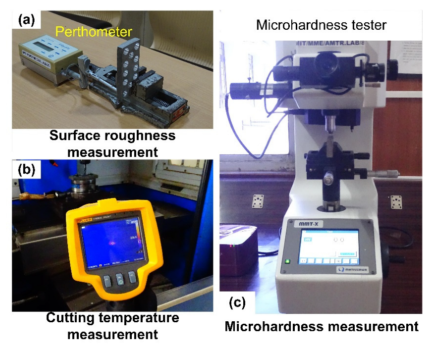
The drilling and helical hole milling experiments were conducted on a Ti6Al4V alloy using a 3-axis computer numeric control (CNC) machine tool setup (make AMC Spark, Bengaluru, India), as illustrated in (Figure 1a). Double-fluted carbide end mills (of diameter 5 mm) were used to conduct the helical milling experiments. Similarly, drilling was performed using a double fluted carbide drill of 6.8 mm diameter, as shown in (Figure 1b). Perthometer (make Taylor Hobson Surtronic 3+, Taylor Hobson, Leicester, UK) having a tip of radius 5 μm was utilized in the measurement of average surface roughness (Ra) of the borehole, as seen in Figure 2a. The evaluation length and sampling were set at 5 mm and 0.8 mm. Measurements were conducted at three distinct positions of an individual hole, and an average of these three values was captured for further analysis. Infra-Red (IR) thermal camera (Fluke-Ti32, Washington, DC, USA) was employed to capture the machining temperature, as shown in (Figure 2b). A matte black paint was coated on the work surface to obtain uniform thermal emissivity (e = 0.95) and accurate results. The work sample was mounted at a distance of 0.1 m from the IR camera. The images of the burrs were captured and measured using a microscope (make Olympus-BX53M, Olympus Corporation, Tokyo, Japan). Four measurements were recorded for an individual hole. The mean values of burr height and width were calculated and utilized in further investigation. The surface texture of machined holes was acquired using an optical microscope (make Olympus-BX53M, Olympus Corporation, Tokyo, Japan). The characteristics of the bore surface were evaluated by sectioning the processed holes in an axial direction by employing a wire-based spark erosion machine. Specimens were polished with SiC grit papers with grit sizes spanning from 600 to 2000. A mirror finish was obtained by employing diamond polishing. The micro-hardness of the polished specimens was assessed with a digital micro-hardness tester (make OmniTech, Sioux Falls, SD, USA) mounted with a diamond-shaped (Vickers, London, UK) indenter by applying 300 g load for 15 s, as shown in (Figure 2c).
The process variables were considered for the comparative analysis based on similar productivity conditions (machining time). In a previous study, it was recommended that the cutting speed is maintained below 60 m/min for prolonged tool life [26], while scant data are available on the selection of axial feed. Therefore, the choice of cutting variables is affected by the recommendation of the cutting tool supplier. Moreover, the study aims to understand the surface roughness, burr size, and microhardness behavior of milled holes. Therefore, a range of values was considered to realize the evolution of the performance measures. Table 1 illustrates the control parameters used in this study. Additionally, under dry conditions, helical milling tests were performed by varying the axial feed (fa) (0.2, 0.4, and 0.6 mm/rev) and cutting speed (Vc) (20, 40, and 60 m/min) at three levels. The tangential feed (ft) was maintained constant at 0.09 mm/z for all the experiments.

3. Results

3.1. Machining Temperature

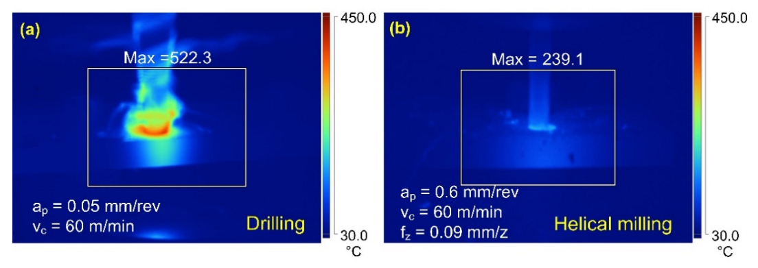
An elevated machining temperature can adversely affect the dimensional accuracy and cutting tool life, induce residual stresses, and cause surface/subsurface damage. Accordingly, the machining temperature data for various trials were analyzed. Figure 3 shows the IR thermal profiles obtained during the drilling and helical milling of holes. The machining temperature observed for the conventional drilling process was 522.3 °C (Figure 3a), while the maximum measured temperature for helical milling was 239.1 °C (Figure 3b).
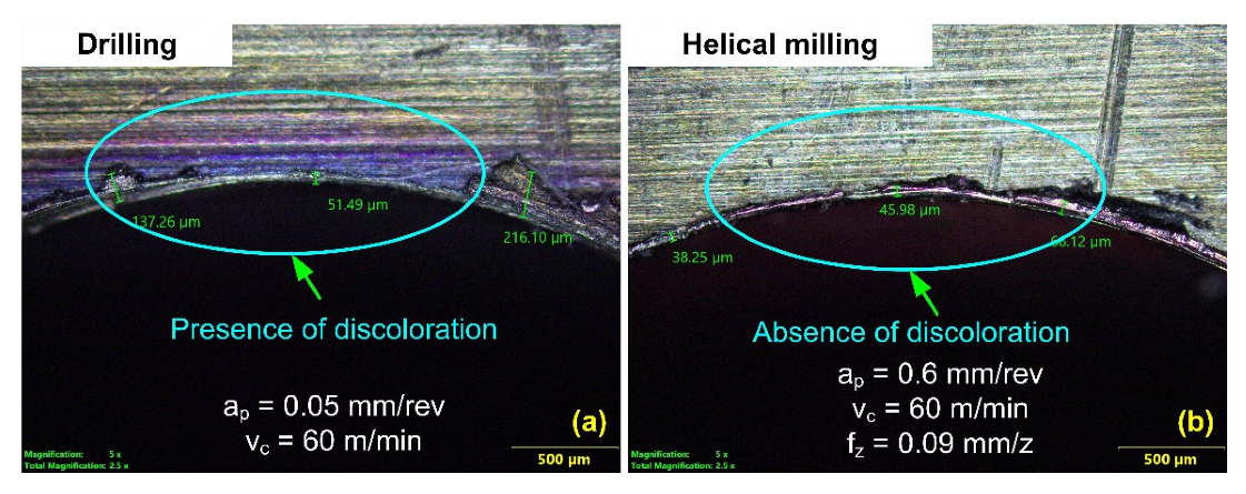
The higher magnitude of the shear zone temperature obtained during the drilling process can be attributed to the process mechanics, such as friction. Drilling involves continuous cutting, and the machining occurs in a confined space. Accordingly, there exists a constant frictional contact at the chip–tool interface. Moreover, owing to the confined nature of machining, the continuous chips produced during the drilling process rub against the machined surface, leading to elevated temperature due to friction load. In addition to the frictional heat, the generation of heat on account of plastic deformation adds up to the machining temperature. Additionally, inadequate heat dissipation owing to the workpiece’s relatively low thermal conductivity also contributes to the rise in temperature. Under similar machining conditions, the temperature generated during helical milling is much lower. The reduction in the shear zone temperature for helical milling is linked to the process kinematics. Helical milling is a cutting process where the work–tool contact is intermittent in nature. Additionally, the size of the bore being machined is much larger than the tool diameter. These conditions help to ease the chip evacuation and friction reduction, thereby reducing the heat build-up and temperature rise. Figure 4 compares the exit edge of the hole made by the two different hole-making techniques. The inspection of the drilled hole revealed the existence of a heat-affected zone (HAZ). Due to hole processing under dry conditions and poor heat dissipation properties of the material, significant heat built-up took place near the hole surface, resulting in HAZ. On the other hand, no discoloration zone was observed in the hole processed using helical milling, indicating the absence of HAZ. In general, helical milling process showcased a better performance in terms of lower machining temperatures and reduced the possibility of HAZ formation.
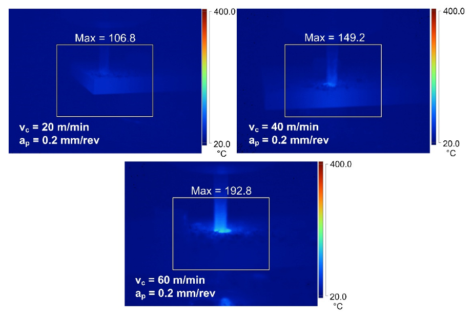
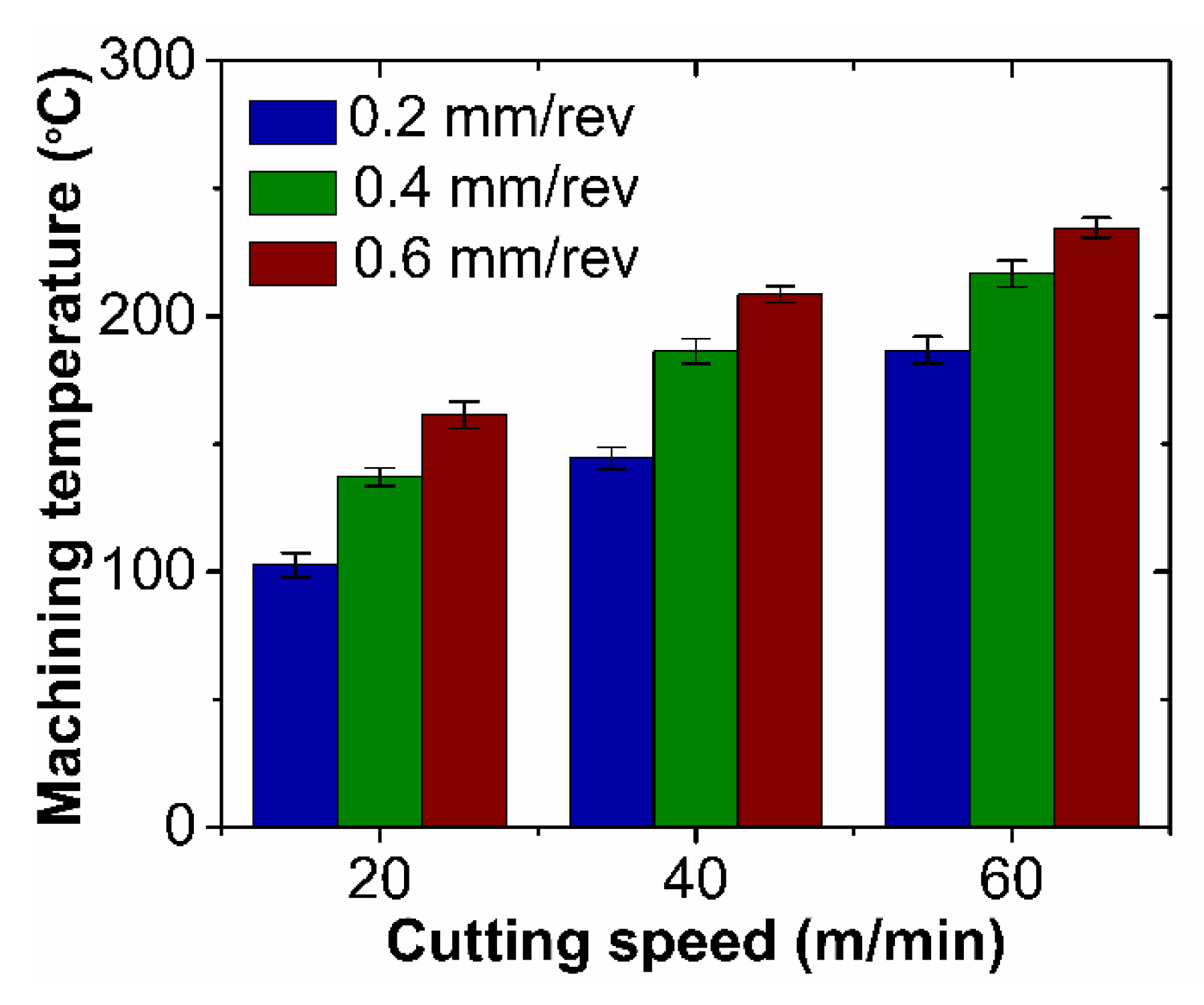
Furthermore, the machining temperature was investigated with different levels of process variables. The influence of cutting speed on machining temperature is illustrated in Figure 4. With an increase in the cutting speed from 20 m/min to 60 m/min, there is an increase in the material deformation rate. A higher plastic deformation leads to hardening, where the process struggles, leading to increased heat generated in the shear zone. In addition, a poor thermal conductivity results in a substantial amount of heat retainment at the cutting zone. All these factors contribute to higher machining temperatures. Figure 5 shows the machining temperature rise for a constant axial feed condition (0.2 mm/rev). A machining temperature of 102.6 °C was noticed for a cutting speed of 20 m/min. The temperature increased to 144.6 °C for a 40 m/min cutting speed. The highest magnitude of temperature (186.7 °C) was recorded at a cutting speed of 60 m/min.
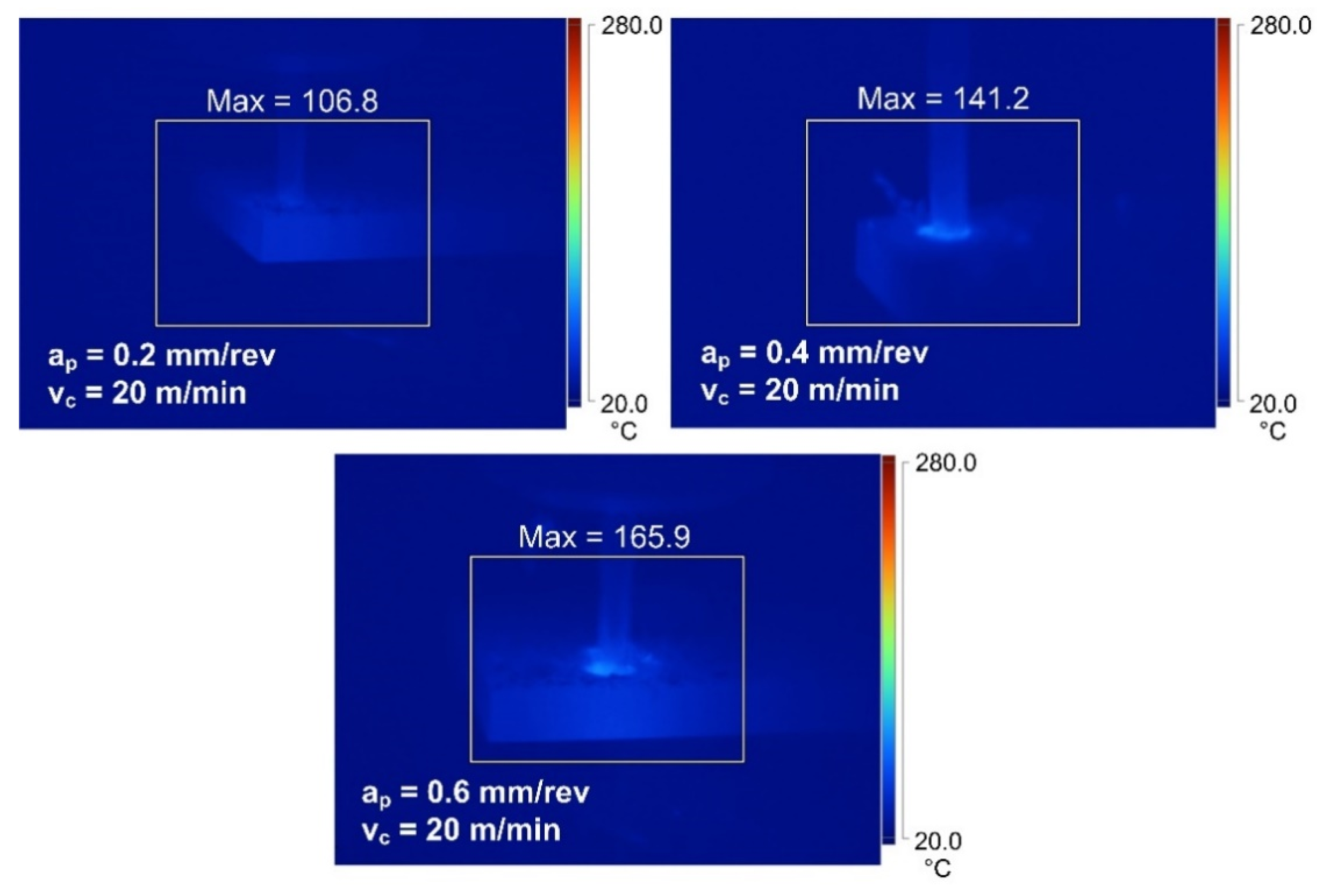
Figure 6 also illustrates the direct influence of axial feed on the machining temperature. A lower machining temperature was noted at an axial feed of 0.2 mm/rev. When the axial feed was set at 0.6 mm/rev, the temperature peaked and reached the highest value. The increase in the machining temperature results from the frictional heat generated because of the increased work–tool interaction and considering the fact that the process is taking place without a coolant. The increase in the machining temperature is verified by Figure 7 for a constant machining speed condition (20 m/min). The machining temperature recorded for the axial feed of 0.2 mm/rev was 102.6 °C. The temperature rose to 137.1 °C for an axial feed of 0.4 mm/rev. The temperature noted was the highest, having a magnitude of 161.4 °C, when the axial feed increased to 0.6 mm/rev. However, the increase in machining temperature is steeper with the cutting speed variations, clarifying the greater effect of cutting speed on machining temperature compared to axial feed during helical milling.

3.2. Surface Roughness

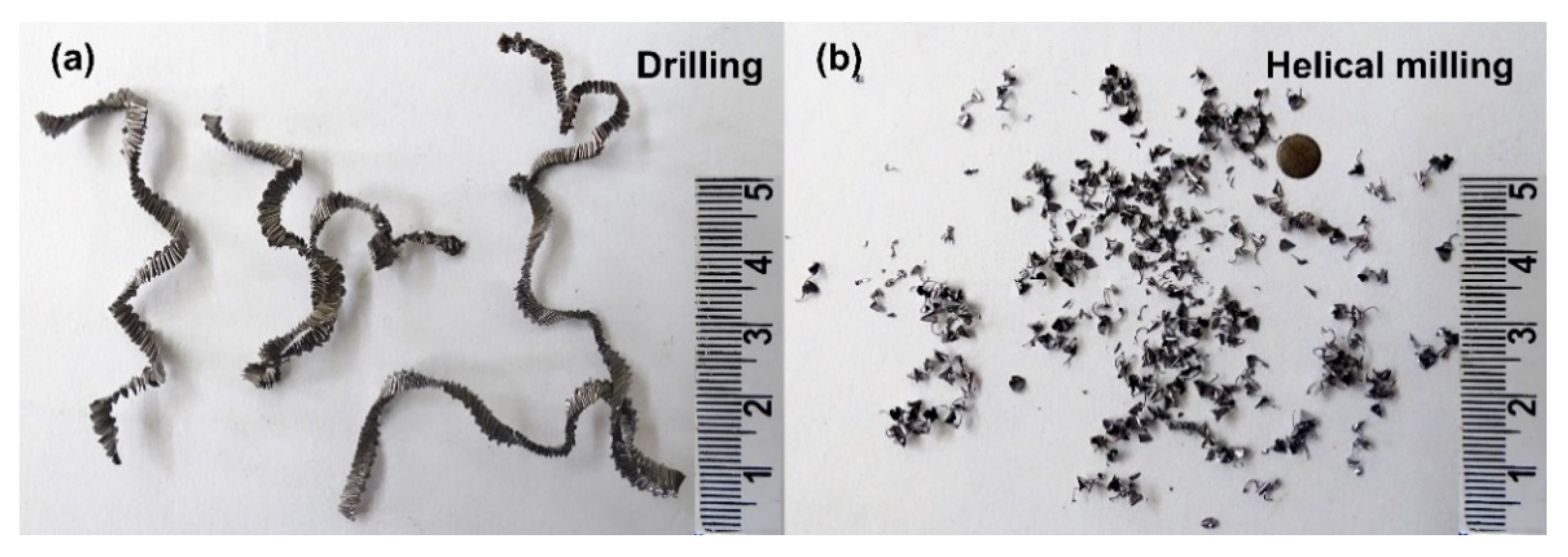
Surface roughness, an index of product quality, determines the functional behavior of a machine component. Therefore, it is essential to analyze the surface of the holes produced using the milling process. Figure 8 displays the machined surface and 2D profiles of boreholes machined using the two processes. The profiles indicate a higher roughness of the hole processed with conventional drilling. The strain-hardened continuous chips (see Figure 9a) rub against the newly generated hole surface, resulting in deep scratches and grooves. Additionally, the larger magnitude of the cutting forces observed during conventional drilling can deflect the cutting tool and result in unstable cutting, thereby contributing to a poor surface finish [23]. On the contrary, the helical milling process is intermittent and generates discontinuous chips (see Figure 9b) and lower cutting forces. Moreover, the difference in the diameter of tool and borehole provides sufficient space for the chips to evacuate effectively, preventing any hard contact between the chips and machined hole surface. Accordingly, a borehole with a superlative surface finish is produced during helical milling.
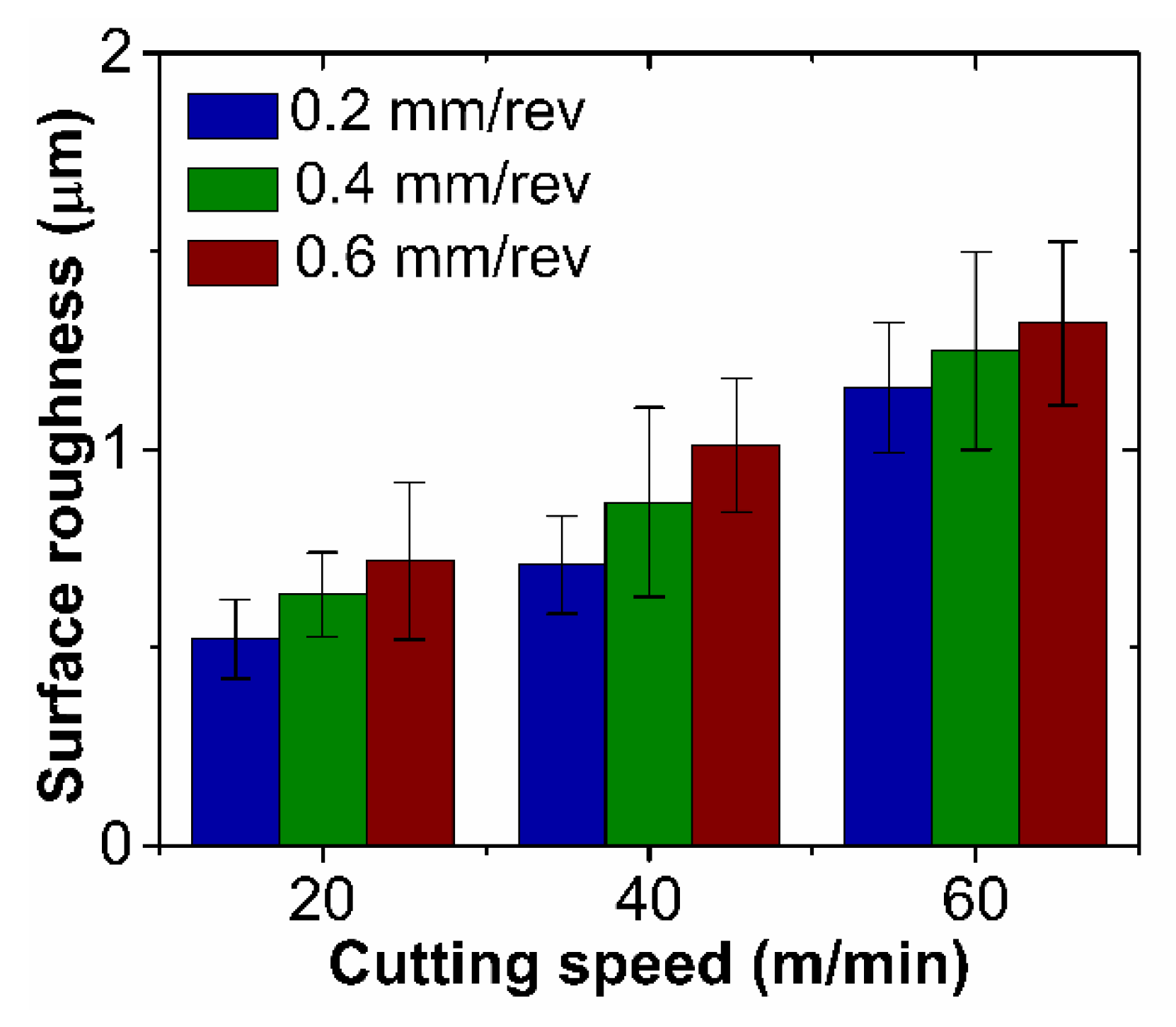
Figure 10 illustrates the behavior of the surface roughness with different values of the process variables during helical milling. The roughness values of the machined surface were observed to increase with the axial feed and cutting speed. As witnessed in Figure 11a, helical milling with a selected cutting speed and axial feed of 20 m/min and 0.2 mm/rev, respectively, resulted in a superior surface finish. The smaller size of the tool in comparison to the bore size provides sufficient space for the chips to evacuate without grazing the machined bore surface. It is also ascertained that boreholes with higher surface roughness were produced at higher cutting speeds (40 and 60 m/min). The axial feed too influenced the surface roughness. At a lower axial feed (0.2 mm/rev and 0.4 mm/rev), a lower surface roughness was recorded. Nevertheless, for a higher value of the tool feed (0.6 mm/rev), the surface roughness increased. A higher surface roughness magnitude was ascribed to the chatter marks (see Figure 11b). At higher axial feed conditions, the overhang length of the tool increases. In such a case, the slender end mill deflects under high loading conditions (chip load), leading to unstable cutting. The surface roughness increased by 98% as the cutting speed increased (20 to 60 m/min), while a moderate increment of 28% was recorded with the axial feed increment (0.2 to 0.6 mm/rev). The highest surface roughness of 1.32 µm was measured at higher levels of cutting speed and feed, while the desirable surface roughness (0.52 µm) was attained when milled with a cutting speed of 20 m/min and feed of 0.2 mm/rev.

3.3. Microhardness

Microhardness is an important surface integrity property that can affect the corrosion and fatigue resistance of the material. Considering its importance, the variable was analyzed for the two hole-making processes. Figure 12a shows the typical microhardness profile for a drilled hole. In the case of conventional drilling, microhardness near the machined bore surface (50 μm) was noted to be 340 HV, which was closer to the bulk hardness of the material (320–340 HV). Small changes in the material hardness can be related to the high machining temperature (522.3 °C), which enables the thermal softening of the workpiece associated with conventional drilling. However, at the subsurface, the microhardness rose to a peak of 372 HV. The rise in the microhardness results from the strain hardening resulting from the material deformation that occurs during the drilling process. Finally, the hardness dropped back to bulk hardness value at a distance of 500–600 μm from the bore surface.
However, the microhardness trend for helical milling deviates from the drilling process. The microhardness near the machined surface was noted to be 368–377 HV, which was significantly higher than the bulk hardness, shown in Figure 12a. In helical milling, the temperature developed during the machining (239.1 °C) is considerably lesser when compared to the phase transformation temperature of the material and, therefore, unable to induce any thermal softening. Therefore, it can be articulated that strain hardening due to deformation under mechanical loading is the major factor for the rise in the microhardness value. Further, the microhardness reached the bulk hardness of the material further away (400–500 μm) from the free surface of the borehole.
Furthermore, the effects of process variables on the microhardness for helical milling operation were analyzed. Figure 12b shows the typical microhardness profiles obtained for various combinations of process parameters. It was noticed that the microhardness profiles followed a similar trend. The microhardness was observed to be very high near the helically milled surface (50 μm). However, with the increase in the distance along the material subsurface (500–600 μm), the microhardness decreased and equaled the bulk hardness value. The cutting speed value impacted the microhardness. The magnitude of microhardness increased as the speed was enhanced from 20 m/min to 60 m/min. The increased hardness is the function of strain hardening originating from excessive mechanical deformation. Though the cutting temperature elevates with the cutting speed (Figure 4), the results suggest the dominance of mechanical deformation on microhardness in helical milling. Additionally, the axial feed was noted to influence the microhardness, as seen in Figure 12b. The subsurface microhardness increased with the feed increment from 0.2 mm/rev to 0.6 mm/rev. The rising of the microhardness is again attributed to the strain hardening due to the increased mechanical deformation. The maximum increase in microhardness of 14% was noted for a speed and feed combination of 60 m/min and feed of 0.6 mm/rev. As reported, the increase in the levels of process variables resulted in excessive mechanical deformation, thus increasing the strain-hardening tendency and the microhardness. Since the strain associated with the mechanical deformation dominates the temperature-controlled strain, compressive residual stress is introduced in the machined surface. Considering the positive influence of compressive strain on fatigue performance, it can be affirmed that helical milling helps to improve the fatigue life of the machined parts.

3.4. Burr Size

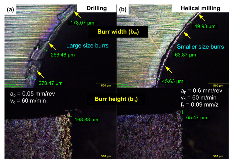
The burrs formed during hole making are undesirable as it needs additional burr removal operations, thus increasing the cost of production. Moreover, large-sized burrs may result in stress concentration and, in turn, reduce the fatigue and fracture resistance of the material. It can damage the fastener or the assembly because of its interference with the seating of fasteners. Considering the importance, burr formation was further examined. Figure 13 illustrates the burrs at the hole exit for the two hole-making techniques. Optical inspection indicated the formation of a highly prominent burr during drilling. Higher values of the thrust force cause large size burrs. As the tool exits from the workpiece, due to the excessive heat, material is plastically stretched before it detaches in the form of an end cap. The uneven material removal after stretching generates large-sized burrs. However, during helical milling, the simultaneous helical and axial motion of the end mill causes the burr cap to separate from the workpiece due to the shearing at the peripheral cutting edge. This results in the generation of burrs of significantly smaller size.
The influence of the process variables during helical milling on the dimensions of the exit burr is depicted in Figure 14. The cutting speed directly influenced the average burr size (height and width). For instance, for a fixed feed (0.2 mm/rev), as the cutting speed increased from 20 to 40 m/min and then to 60 m/min, the average height of the burrs increased from 25–35 μm to 36–48 μm and 51–62 μm, respectively. Statistically, an 82% increase in the burr height was noted as the cutting speed and feed increased to their highest levels.
Similarly, the average width of the burr also increased from 16–38 μm to 22–50 μm and then to 21–72 μm for the chosen cutting speeds (see Figure 15), indicating a 76% increase. The machining temperature impacts the burr size and plays a crucial role. A substantial amount of heat is retained in the work material at higher cutting speeds, causing the material to thermally soften. The resulting increase in ductility enhances the flowability of the material. At the exit of the hole, the tool pushes out the stretched material, thereby resulting in exit burrs of a larger size. As indicated, the size of the burrs increased with the cutting speed and axial feed. However, burrs were significantly smaller than the ones formed during the drilling process, thus reinforcing the advantage helical milling has over the drilling process.
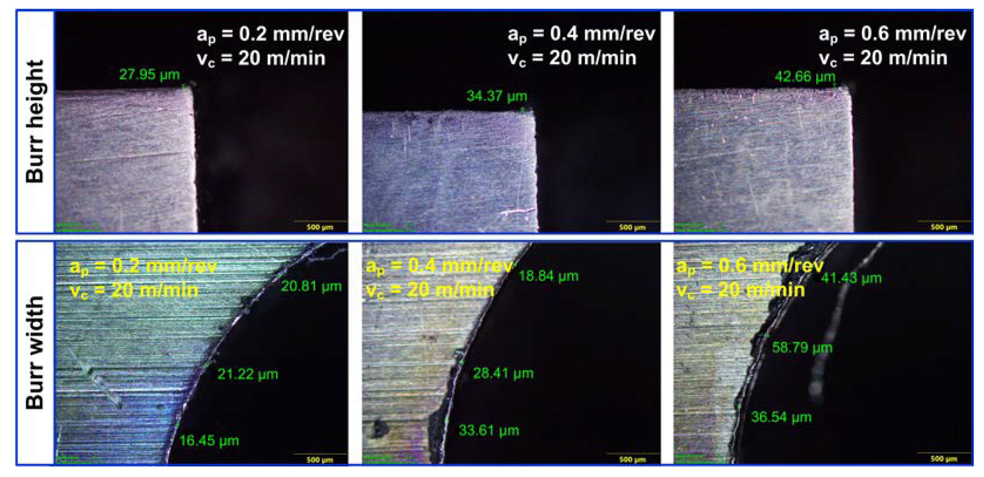
Figure 16 shows the relationship between axial feed and burr size. The axial feed directly influences the size of the exit burr (height and width). For a fixed cutting speed of 20 m/min, Figure 16 illustrates that an increase in feed from 0.2 to 0.4 mm/rev and then to 0.6 mm/rev resulted in an increased average burr height from 25–35 μm to 30–43 μm and 40–47 μm, respectively. Similarly, average burr width increased from 16–38 μm to 18–44 μm and 36–59 μm, as feed increased from 0.2 to 0.4 mm/rev and 0.6 mm/rev, respectively. A large-sized exit burr was ascribed to the thrust force magnitude. Rising thrust force aids in the deformation and plastic stretching of the workpiece material, thereby increasing the size of exit burrs.

4. Conclusions

This study presented an elaborate work on the helical hole milling of Ti6AL4V alloy considering the machining temperature, surface roughness, microhardness, and burr size. Accordingly, the following are the conclusions:
  • Helical milling resulted in a lower machining temperature than the drilling process due to the effective chip evacuation and intermittent contact between the workpiece and cutting. Further, dry helical milling resulted in a significantly smaller heat-affected zone (HAZ). The temperature increased with the cutting speed and axial feed increment. The highest machining temperature of 234.7 °C was recorded at 60 m/min cutting speed and a feed of 0.6 mm/rev. The results illustrate that lower cutting temperatures could be achieved by employing a lower cutting speed of 20 m/min and axial feed of 0.2 mm/rev.
  • Helical milling kinematics influenced the hole surface finish. The discontinuous nature of the chips generated helped in the scratch-free evacuation of the machining zone for all cutting speeds and lower axial feeds. The deflection of the end mill due to the side loading at higher axial feeds caused chatter, thereby deteriorating the surface quality. Surface roughness increased by 98% when the cutting speed increased to 60 m/min from 20 m/min, while a moderate increment of 28% was observed when the axial feed increased to 0.6 mm/rev from 0.2 mm/rev. Desirable surface roughness (0.52 µm) was attained when milled with a cutting speed of 20 m/min and feed of 0.2 mm/rev.
  • Helical milling process demonstrated a substantial advantage in terms of smaller-sized burrs. The dimensions of the exit burrs were significantly influenced by the cutting speed and axial feed. Mechanical thrust load and machining temperature significantly contributed to the size of the burrs formed. A smaller-sized burr can be obtained at a speed of 20 m/min and an axial feed of 0.2 mm/rev.
  • The microhardness of the helically milled surface was greater than the drilled surface. In conventional drilling, strain hardening and thermal softening influence the microhardness of the bore surface. Strain hardening due to deformation under mechanical loading increased the microhardness value in dry helical milling. Moreover, the subsurface microhardness is enhanced with the rise in axial feed and cutting speed during helical milling.
From the outcomes of the present work, it is concluded that helical milling is a suitable process for hole making in difficult-to-machine materials, such as titanium alloys. The process can generate lower machining temperatures, burr size, and surface roughness compared to the drilling process. Furthermore, the dominance of mechanical deformation-dependent stain introduces compressive residual stress, which positively influences fatigue performance, thus affirming the usefulness of helical milling process. However, considering the difficult-to-machine nature of the material, a need still exists to appraise the behavior of the cutting tools while considering tool wear and process productivity.

Author Contributions

Conceptualization, methodology, formal analysis, investigation, resources, and data curation, R.S., S.S.B. and G.B.; writing—original draft preparation, G.B. and U.K.; writing—review and editing, U.K., R.S., S.S.B. and A.P.; visualization, G.B. and A.P.; supervision, G.B. and S.S.B. All authors have read and agreed to the published version of the manuscript.

Funding

This research received no external funding.

Data Availability Statement

All the data included in the manuscript can be provided by the corresponding author upon reasonable request.

Conflicts of Interest

The authors declare no conflict of interest.

References

  1. Ezugwu, E.O.; Wang, Z.M. Titanium alloys and their machinability—A review. J. Mater. Process. Technol. 1997, 68, 262–274. [Google Scholar] [CrossRef]
  2. Machado, A.R.; Wallbank, J. Machining of titanium and its alloys—A review. Proc. Inst. Mech. Eng. Part B J. Eng. Manuf. 1990, 204, 53–60. [Google Scholar] [CrossRef]
  3. Parida, A.K. Simulation and experimental investigation of drilling of Ti-6Al-4V alloy. J. Lightweight Mater. Manuf. 2018, 1, 197–205. [Google Scholar] [CrossRef]
  4. Cui, C.; Hu, B.; Zhao, L.; Liu, S. Titanium alloy production technology, market prospects and industry development. Mater. Des. 2011, 32, 1684–1691. [Google Scholar] [CrossRef]
  5. Hale, J. Boeing 787 from the ground up. Aero 2006, 4, 7. [Google Scholar]
  6. Hogan, B.J. Automation speeds A380 wing assembly. Manuf. Eng. 2005, 134, 121–131. [Google Scholar]
  7. Sharif, S.; Rahim, E.A. Performance of coated-and uncoated-carbide tools when drilling titanium alloy—Ti–6Al4V. J. Mater. Process. Technol. 2007, 185, 72–76. [Google Scholar] [CrossRef] [Green Version]
  8. Bandapalli, C.; Singh, K.K.; Sutaria, B.M.; Bhatt, D.V. Experimental investigation of machinability parameters in high-speed micro-end milling of titanium (grade-2). Int. J. Adv. Manuf. Technol. 2016, 85, 2139–2153. [Google Scholar] [CrossRef]
  9. Pervaiz, S.; Rashid, A.; Deiab, I.; Nicolescu, M. Influence of tool materials on machinability of titanium-and nickel-based alloys: A review. Mater. Manuf. Process. 2014, 29, 219–252. [Google Scholar] [CrossRef]
  10. Cantero, J.L.; Tardio, M.M.; Canteli, J.A.; Marcos, M.; Miguelez, M.H. Dry drilling of alloy Ti–6Al–4V. Int. J. Mach. Tool. Manu 2005, 45, 1246–1255. [Google Scholar] [CrossRef] [Green Version]
  11. Kumar, B.S.; Baskar, N. Integration of fuzzy logic with response surface methodology for thrust force and surface roughness modeling of drilling on titanium alloy. Int. J. Adv. Manuf. Technol. 2013, 65, 1501–1514. [Google Scholar] [CrossRef]
  12. Prabukarthi, A.; Krishnaraj, V.; Santhosh, M.; Senthilkumar, M.; Zitoune, R. Optimisation and tool life study in drilling of titanium (Ti-6Al-4V) alloy. Int. J. Mach. Mach. Mater. 2013, 13, 138–157. [Google Scholar] [CrossRef]
  13. Varote, N.; Joshi, S.S. Microstructural Analysis of Machined Surface Integrity in Drilling a Titanium Alloy. J. Mater. Eng. Perform. 2017, 26, 4391–4401. [Google Scholar] [CrossRef]
  14. Balaji, M.; Rao, K.V.; Rao, N.M.; Murthy, B.S.N. Optimization of drilling parameters for drilling of TI-6Al-4V based on surface roughness, flank wear and drill vibration. Measurement 2018, 114, 332–339. [Google Scholar] [CrossRef]
  15. Waqar, S.; Asad, S.; Ahmad, S.; Abbas, C.A.; Elahi, H. Effect of drilling parameters on hole quality of Ti-6Al-4V titanium alloy in dry drilling. Mater. Sci. Forum 2017, 880, 33–36. [Google Scholar] [CrossRef]
  16. Eltaggaz, A.; Deiab, I. Comparison of between direct and peck drilling for large aspect ratio in Ti-6Al-4V alloy. Int. J. Adv. Manuf. Technol. 2019, 102, 2797–2805. [Google Scholar] [CrossRef]
  17. Dedeakayoğulları, H.; Kaçal, A.; Keser, K. Modeling and prediction of surface roughness at the drilling of SLM-Ti6Al4V parts manufactured with pre-hole with optimized ANN and ANFIS. Measurement 2022, 203, 112029. [Google Scholar] [CrossRef]
  18. Ming, W.; Dang, J.; An, Q.; Chen, M. Chip formation and hole quality in dry drilling additive manufactured Ti6Al4V. Mater. Manuf. Proc. 2020, 35, 43–51. [Google Scholar] [CrossRef]
  19. Soori, M.; Arezoo, B. Cutting tool wear minimization in drilling operations of titanium alloy Ti-6Al-4V. Proc. Inst. Mech. Eng. Part J J. Eng. Tribol. 2023, 237, 1250–1263. [Google Scholar] [CrossRef]
  20. Pramanik, A. Problems and solutions in machining of titanium alloys. Int. J. Adv. Manuf. Technol. 2014, 70, 919–928. [Google Scholar] [CrossRef]
  21. Sun, S.; Brandt, M.; Dargusch, M.S. Thermally enhanced machining of hard-to-machine materials—A review. Int. J. Mach. Tool. Manu 2010, 50, 663–680. [Google Scholar] [CrossRef]
  22. Park, K.H.; Beal, A.; Kwon, P.; Lantrip, J. Tool wear in drilling of composite/titanium stacks using carbide and polycrystalline diamond tools. Wear 2011, 271, 2826–2835. [Google Scholar] [CrossRef]
  23. Zeilmann, R.P.; Weingaertner, W.L. Analysis of temperature during drilling of Ti6Al4V with minimal quantity of lubricant. J. Mater. Process. Technol. 2006, 179, 124–127. [Google Scholar] [CrossRef]
  24. Ahmed, L.S.; Govindaraju, N.; Pradeep Kumar, M. Experimental investigations on cryogenic cooling in the drilling of titanium alloy. Mater. Manuf. Process. 2016, 31, 603–607. [Google Scholar] [CrossRef]
  25. Kashyap, N.; Rashid, R.A.R.; Khanna, N. Carbon emissions, techno-economic and machinability assessments to achieve sustainability in drilling Ti6Al4V ELI for medical industry applications. Sustain. Mater. Technol. 2022, 33, e00458. [Google Scholar] [CrossRef]
  26. Li, H.; He, G.; Qin, X.; Wang, G.; Lu, C.; Gui, L. Tool wear and hole quality investigation in dry helical milling of Ti-6Al-4V alloy. Int. J. Adv. Manuf. Technol. 2014, 71, 1511–1523. [Google Scholar] [CrossRef]
  27. Zhao, Q.; Qin, X.; Ji, C.; Li, Y.; Sun, D.; Jin, Y. Tool life and hole surface integrity studies for hole-making of Ti6Al4V alloy. Int. J. Adv. Manuf. Technol. 2015, 79, 1017–1026. [Google Scholar] [CrossRef] [Green Version]
  28. Sun, D.; Lemoine, P.; Keys, D.; Doyle, P.; Malinov, S.; Zhao, Q.; Qin, X.; Jin, Y. Hole-making processes and their impacts on the microstructure and fatigue response of aircraft alloys. Int. J. Adv. Manuf. Technol. 2018, 94, 1719–1726. [Google Scholar] [CrossRef] [Green Version]
  29. Akula, S.; Nayak, S.N.; Bolar, G.; Managuli, V. Comparison of conventional drilling and helical milling for hole making in Ti6Al4V titanium alloy under sustainable dry condition. Manuf. Rev. 2021, 8, 12. [Google Scholar] [CrossRef]
  30. Festas, A.J.; Pereira, R.B.; Ramos, A.; Davim, J.P. A study of the effect of conventional drilling and helical milling in surface quality in titanium Ti-6Al-4V and Ti-6AL-7Nb alloys for medical applications. Arab. J. Sci. Eng. 2021, 46, 2361–2369. [Google Scholar] [CrossRef]
  31. Ge, J.; Reji, R.; Feist, T.; Elmore, A.; McClelland, J.; Higgins, C.; McLaughlin, B.; Jin, Y.; Sun, D. Investigating hole making performance of Al 2024-T3/Ti-6Al-4V alloy stacks: A comparative study of conventional drilling, peck drilling and helical milling. Int. J. Adv. Manuf. Technol. 2022, 120, 5027–5040. [Google Scholar] [CrossRef]
Figure 1. (a) Arrangement for conducting the machining experiments. (b) Cutting tools used in the present study.
Lubricants 11 00349 g001
Figure 2. (a) Surface roughness measurement. (b) Cutting temperature measurement. (c) Micro-hardness measurement.
Lubricants 11 00349 g002
Figure 3. (a) Temperature during hole drilling. (b) Temperature during helical milling.
Lubricants 11 00349 g003
Figure 4. (a) Workpiece coloration indicating HAZ in a drilled hole. (b) Absence of HAZ in a helical milled hole.
Lubricants 11 00349 g004
Figure 5. Infrared thermograph indicating the machining temperature at different cutting speeds.
Lubricants 11 00349 g005
Figure 6. Effect of cutting speed and axial feed on machining temperature.
Lubricants 11 00349 g006
Figure 7. Infrared thermograph indicating the machining temperature at different axial feeds.
Lubricants 11 00349 g007
Figure 8. Machined surface and 2D profile of the borehole produced with (a) drilling and (b) helical milling.
Lubricants 11 00349 g008
Figure 9. (a) Continuous chips during drilling. (b) Discontinuous chips during helical milling.
Lubricants 11 00349 g009
Figure 10. Surface roughness vs. helical milling parameters.
Lubricants 11 00349 g010
Figure 11. (a) Bore surface indicating smooth finish. (b) Bore surface indicating chatter.
Lubricants 11 00349 g011
Figure 12. (a) Microhardness profiles of the drilled and helical-milled holes. (b) Variation of the maximum microhardness during helical milling.
Lubricants 11 00349 g012
Figure 13. Exit burrs at the hole periphery. (a) Drilling process. (b) Helical milling process.
Lubricants 11 00349 g013
Figure 14. Burr height and width variation with the process parameters.
Lubricants 11 00349 g014
Figure 15. Size of the burr with different cutting speed conditions.
Lubricants 11 00349 g015
Figure 16. Size of the burr with different axial feed conditions.
Lubricants 11 00349 g016
Table 1. Process variables for comparative assessment.
Process VariablesDrillingHelical Milling
Cutting speed (m/min)6060
Axial Feed (mm/rev)0.050.6
Tangential feed (mm/z)-0.09
Machining time (s)2223
Disclaimer/Publisher’s Note: The statements, opinions and data contained in all publications are solely those of the individual author(s) and contributor(s) and not of MDPI and/or the editor(s). MDPI and/or the editor(s) disclaim responsibility for any injury to people or property resulting from any ideas, methods, instructions or products referred to in the content.