Article

Influence of Grease Properties on False Brinelling Damage of Rolling Bearings

1
Tribo Technologies GmbH, 39179 Barleben, Germany
2
Chair of Machine Elements and Tribology, Otto von Guericke University Magdeburg, 39106 Magdeburg, Germany
*
Author to whom correspondence should be addressed.
Lubricants 2023, 11(7), 279; https://doi.org/10.3390/lubricants11070279
Submission received: 24 May 2023 / Revised: 22 June 2023 / Accepted: 26 June 2023 / Published: 28 June 2023

Abstract

:
False brinelling damage in rolling bearings can lead to reduced component lifetimes and increased noise emissions, adversely affecting machine performance. Therefore, minimizing or avoiding such damage is very important. Environmental or operating conditions that can lead to false brinelling damage often cannot be avoided. Alternatively, such damage can be significantly reduced with suitable lubricants. This study utilized a test method from the research project FVA 540 to examine the impact of the base oil viscosity and NLGI class of greases on false brinelling damage at different temperatures. The results showed a clear dependency between the base oil viscosity of greases and the extent of false brinelling damage. Two different thickeners (lithium hydroxystearate/diurea) and different base oil types (PAO/esters) were investigated for this purpose. The results indicate that temperature had a significant effect on the physical and rheological properties of greases and show the potential for reducing false brinelling damage through the selection of appropriate lubricants. These results provide valuable information to improve the performance and lifetime of rolling bearings in industrial settings.

Graphical Abstract

1. Introduction

False brinelling is a wear phenomenon in standstill rolling bearings that are subjected to dynamic radial and/or axial loads and/or oscillating movements with very small amplitudes. False brinelling is tribologically induced damage and not a trough-shaped indentation (true brinelling) as a result of overloading. This was first described by Almen in 1937 for wheel bearings [1]. As a result of small oscillations and dynamic loading, the damage mechanisms adhesion, fatigue, and fretting corrosion occur significantly in false brinelling, with cracks forming on the surface and growing in depth due to the high frictional shear stresses. At small pivot angles (rolling distance < width of contact ellipse), the damage pattern is usually characterized by three distinct areas [2] (Figure 1a). In the center, there is an undamaged area since there is a sliding-free rolling motion between the rolling element and the raceway. This area is surrounded by an annular area where sliding between the rolling element and raceway takes place and fatigue damage develops, which is often superimposed by corrosion. In the outer area, smoothing of the rough surfaces or tribochemical discoloration can be observed.
As the pivot angle increases (rolling distance > width of contact ellipse), these three areas disappear more and more, resulting in a closed surface characterized by fatigue and corrosion (Figure 1b). At very large pivot angles (rolling distance >> width of contact ellipse), the wear mechanism changes from fatigue to abrasion characterized by polished areas [3] (Figure 1c).
The dynamic loads with very small oscillating movements can, for example, be triggered by vibrations of machines or aggregates or occur during transport by truck [4], railway [5], or ship [1]. Moreover, similar loads can occur in the blade bearings of wind turbines, spindle bearings of hammering machining tools [6], bearings of robots, or motorbike steering head bearings [2,7,8]. Grease-lubricated rolling bearings are widely used in all branches of mechanical engineering due to their low design complexity and cost-effective operation compared with oil-lubricated bearings. However, grease-lubricated rolling bearings are much more susceptible to false brinelling [1,9,10,11]. Often, the greases used are not developed for stationary bearings under dynamic loads, but for rotating operation, whereby an elastohydrodynamic lubricating film is formed.
If machines, vehicles, or plants are put into operation with rolling bearings damaged by false brinelling during standstill, it can cause increased running noises, but also early failures due to fatigue damage, depending on the extent of the damage. As a result, unforeseen repair work becomes necessary, which leads to high machine downtime and repair costs.
To avoid such unexpected costs and plant downtimes, machine and vehicle manufacturers and bearing and lubricant manufacturers are developing specific lubricating greases for use under false brinelling conditions, in addition to other measures. To test the suitability of such greases, test rigs can be used. The most popular of these are the Fafnir test rig according to ASTM D4170 [12] and the SNR FEB2 test rig [7] and SRV-Fretting test according to ASTM D7594 [13]. Some additional examples are given in [7,11]. Transport tests can also be carried out. Since transport tests are very cost-intensive and time-consuming, a rolling bearing test rig for highly dynamic loads and movements was developed in [9] that allows for a lubricant’s testing under a wide range of parameters (Section 2.1).
The extent of damage under false brinelling conditions can be influenced by the selection of the bearing type, the load and environmental conditions, and the lubricant. In a comparison of tapered roller bearings, radial deep groove ball bearings, and angular contact ball bearings, it was found in [9,10] that tapered roller bearings produced less damage than radial deep groove ball bearings under comparable conditions. In this comparison, the greatest damage occurred with the angular contact ball bearings. The differences were explained by the fact that spin slip and differential slip increase false brinelling damage, where both types of slip occur with angular contact ball bearings. With radially loaded radial deep groove ball bearings, no spin slip exists, and with tapered roller bearings, spin and differential slip are absent.
For the lubricating grease, various parameters are important. On the one hand, the composition of the grease (thickener, base oil, additives, solid lubricants, etc.) is an essential factor [7,10]; on the other hand, the physical–rheological properties play a significant role. In [14,15], the influence of base oil viscosity and grease consistency was investigated. In [15], groove widths were defined as an evaluation criterion. This investigation showed that consistency should not be evaluated alone. In [14], it was shown with the help of a subjective evaluation (school grade scale) that the damage was lower for greases with a high base oil viscosity than for greases with a lower base oil viscosity, even if the NLGI class of the grease was somewhat lower. In [8], polypropylene grease with PAO base oil with lower viscosity and higher oil separation was estimated as the best among the studied samples for the blade bearings of wind turbines. In [16], greases with lithium hydroxystearate as a thickener and PAO base oils with different viscosities (ν40 = 26/48/211/413 cSt) were investigated for false brinelling wear at room temperature, and the maximal wear depth was evaluated. Furthermore, tests using only base oils were performed. The study revealed that for small amplitudes, lower-viscosity oils and greases with lower-viscosity base oils effectively reduced false brinelling damage. Additionally, it was observed that base oils generally cause less damage than their corresponding greases. In [7], significant increases in false-brinelling damage at −10 °C compared to room temperature and +50 °C were reported. Restricted oil release and poorer flow behavior of the greases could be a reason for this phenomenon. However, some greases also showed almost no influence or even the opposite behavior at low temperatures.
Based on the test rig and test method developed in [9], greases with lithium complex soap and polyurea thickener with PAO base oil and different additives and solid lubricants were tested at room temperature and −20 °C [10]. Generally, greases with polyurea thickener provided a higher level of false brinelling damage compared with lithium complex thickener. Furthermore, at −20 °C, the investigated additives were unable to develop a damage-reducing effect. The activation energies required for additive reactions are probably not achieved at low temperatures. At room temperature, significant wear-reducing effects could be achieved in some cases through additive inclusion. With the lithium complex grease and the combination of an anti-corrosion and an anti-wear additive, the extent of damage could be reduced by 80% compared with lubrication with the lithium complex base grease without any additives. In [10], it was found that with the investigated greases, high oil separation, low shear viscosity, and low loss modulus of greases could reduce false brinelling damage.
In the following, the influence of the base oil viscosity, base oil, and thickener type or the NLGI class on the extent of damage under false brinelling conditions at different temperatures (down to −40 °C) was shown based on the test rig and the test method developed in [9]. Moreover, the correlation between the extent of the false brinelling wear and the temperature, the oil separation, and the shear viscosity was evaluated. The potential for reducing false brinelling damage is presented.

2. Materials and Methods

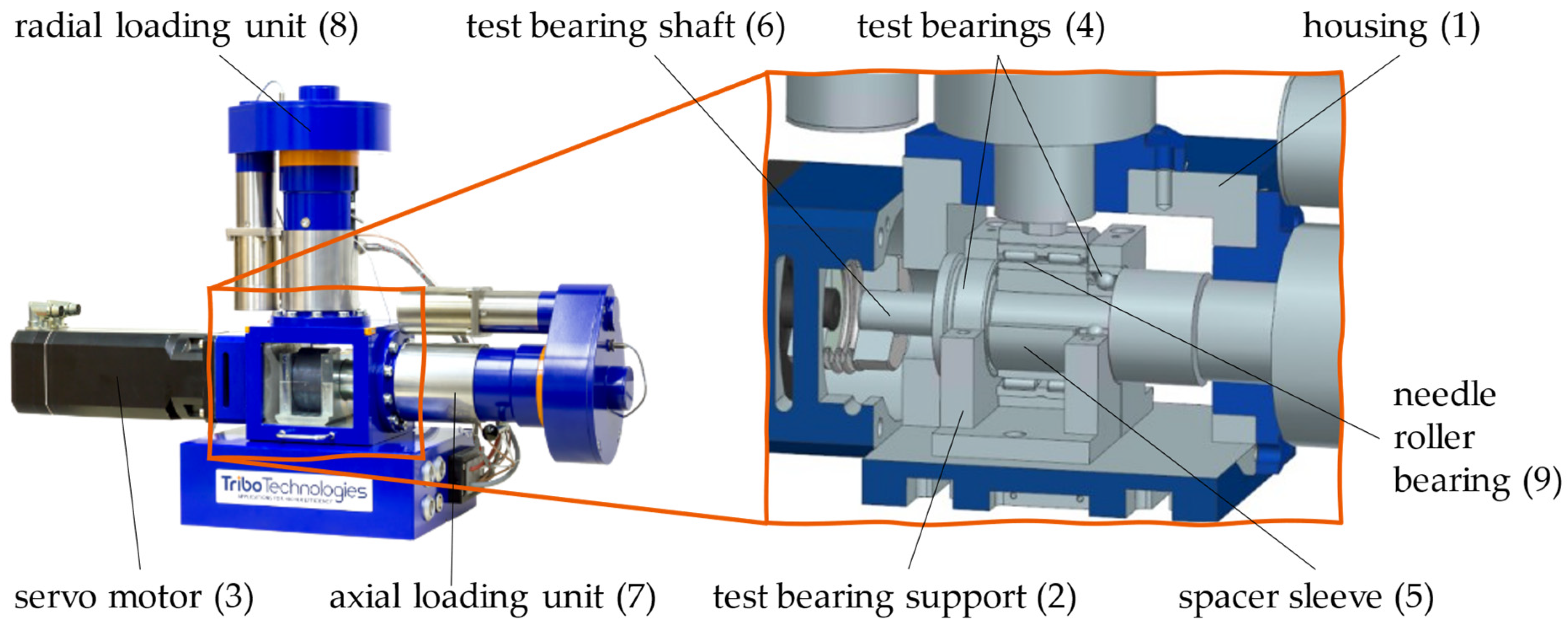
2.1. False Brinelling Test Rig

A false brinelling test rig was used to test lubricants’ suitability under false brinelling conditions. Two test bearings (2× angular contact ball bearings 7205 or 2× tapered roller bearings 32005) were subjected to dynamic loads and/or pivot movements with small angular amplitudes. In addition, a grease distribution cycle could be carried out during rotating operations to create conditions close to those in practice.
Figure 2 shows the false brinelling test rig, which consisted of a housing (1), test bearing support (2), and servo motor (3), as well as two loading units for static and dynamic loading of the bearing arrangement in the axial and radial directions. All power and signal cables were brought together at the base of the test stand and bundled from there to the control cabinet, which is not shown here. To realize practical environmental conditions for the test bearings (4), the entire test setup could be integrated into a climate chamber so that the tests could be carried out in a temperature range between −40 °C and +40 °C.
The inner rings of the test bearings and a spacer sleeve (5) were mounted on the test bearing shaft (6) through an interference fit in such a way that the bearings had an X arrangement. The bearing’s outer rings were supported radially on the bearing support. The axial force was pointed into the housing on the motor side via a support ring. The axial load was applied from the opposite side via the axial loading unit (7). The radial force is applied via the radial loading unit (8) into a needle roller bearing, which loaded the test bearing shaft (6). The interposed needle roller bearing (9) was necessary to avoid impairing the shaft’s freedom of rotation. A spindle driven by a geared motor was installed in each loading unit to apply the static preload forces. In addition, a dynamic load could be applied with the integrated piezo actuators. Load cells were installed in the load units to measure and control the axial and radial loads. In Table 1, the parameters of the false brinelling test rig are summarized.

2.2. Methodology

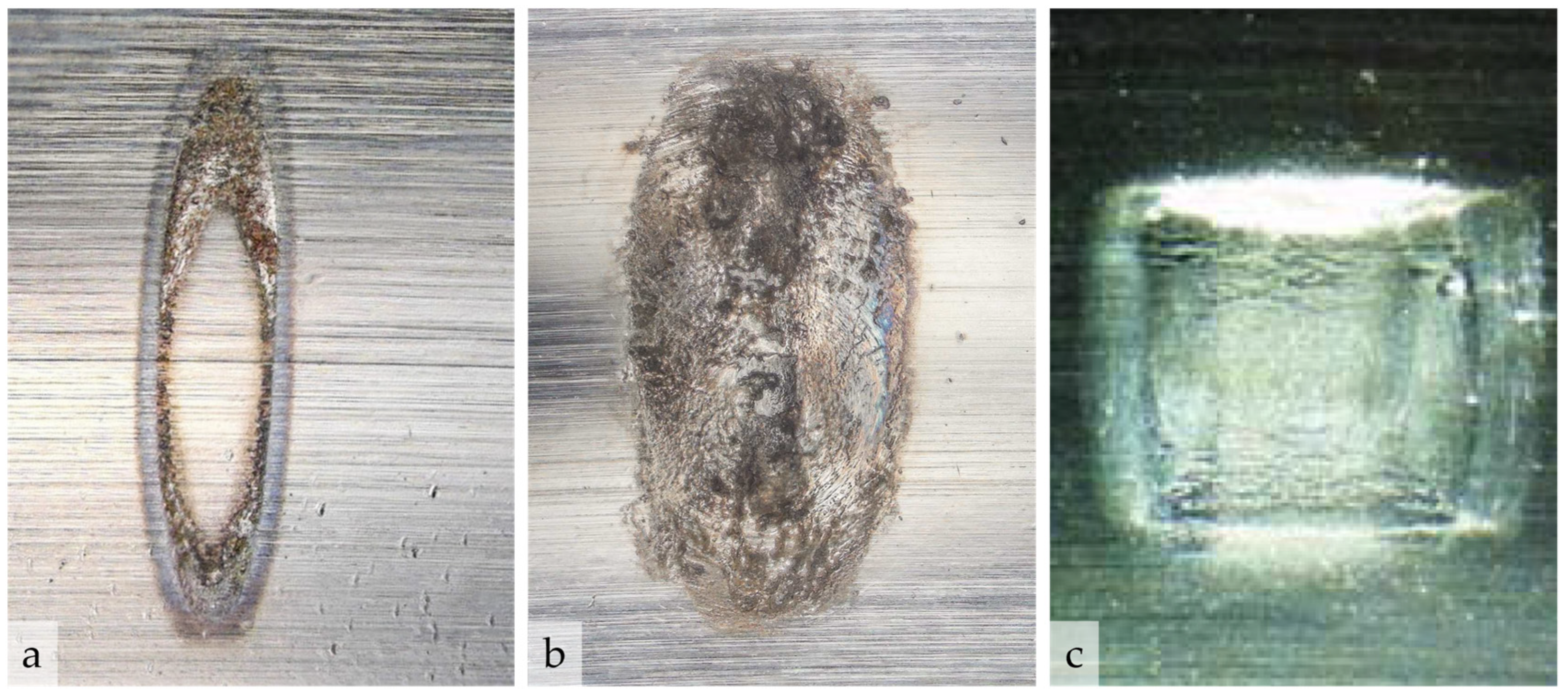
2.2.1. Test Bearing Preparation

To achieve reproducible test results, conscientious and unified test preparation was required. As is standard, angular contact ball bearings of type 7205-B-XL-JP with a sheet metal cage were used for the false brinelling test. To prevent the test bearings from corroding during transport and storage, they were conserved by the manufacturer. To avoid an effect of the conservation on the false brinelling behavior, the bearings were thoroughly cleaned in a three-stage cleaning process in several cleaning baths with a mixture of cyclohexane (80%) and isopropanol (20%). This is usually followed directly by greasing the test bearings with 4 mL of grease using a disposable syringe. In this way, the effectiveness of the grease alone can be tested. Alternatively, a new corrosion treatment can be done before greasing to investigate the interaction of the conservation agent and the grease during false brinelling.

2.2.2. Grease Distribution

A defined grease distribution cycle was necessary to ensure defined lubrication conditions and raceway and rolling element surfaces were completely wetted with grease in the test bearings before each test. During the grease distribution cycle, the test bearings were axially loaded with Fax = 2.7 kN (C/P = 10) and driven in rotation for 30 min at a speed of n = 800 rpm. Experience shows that regardless of the grease, after this time, rolling element surfaces are completely wetted and a uniform grease distribution has formed on the bearing so that subsequently reproducible false brinelling damage can be realized. To better reproduce the transport of new components, machines, or vehicles, tests with a shortened running procedure are necessary. For this purpose, a short running-in procedure was established, which was carried out for only 5 min at a reduced speed of n = 250 rpm.

2.2.3. False Brinelling Test

In [9,10], a test scenario was developed in which the bearing arrangement was preloaded axially and radially. In addition, the vertical piezo actuator applied a dynamic load component in the radial direction. Simultaneously, the servo drive set the bearing inner rings into an oscillating pivot motion. With this loading scenario, typical false brinelling marks can be generated within a short test time. In addition, with these test parameters, a very good differentiation of different lubricants was possible based on the damage after false brinelling tests. Since the transport of machines, vehicles, or components can take place in the most diverse regions of the world, and thus, the lubricating greases must be capable of performing at different temperatures, the test should be carried out at any temperature between −40 °C and +40 °C. In the current study, tests were performed using two false brinelling test rigs. One of them was integrated into a climate chamber to perform low-temperature tests. Second, one was placed outside of the climate chamber. The environmental conditions (air temperature and humidity) of both setups were carefully documented. For the low-temperature setup, a constant temperature of −39 ± 0.5 °C and humidity of 65 ± 3% could be achieved. For the room temperature setup (hereafter RT), the temperatures were between 22 °C and 27 °C and the humidity ranged from 30% to 45%. To achieve meaningful false brinelling damage that could be differentiated between different greases, a test time of approx. 27 h 47 min (corresponding to 0.5 Mio cycles at a pivot frequency of 5 Hz) was shown to be effective Standard parameters of the false brinelling test are collected in Table 2.

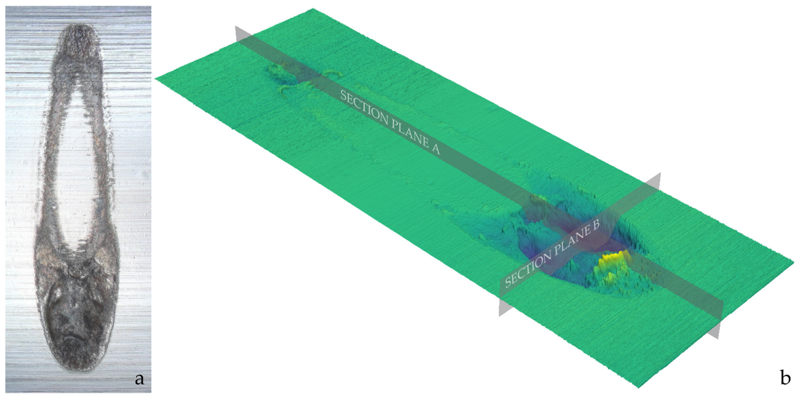
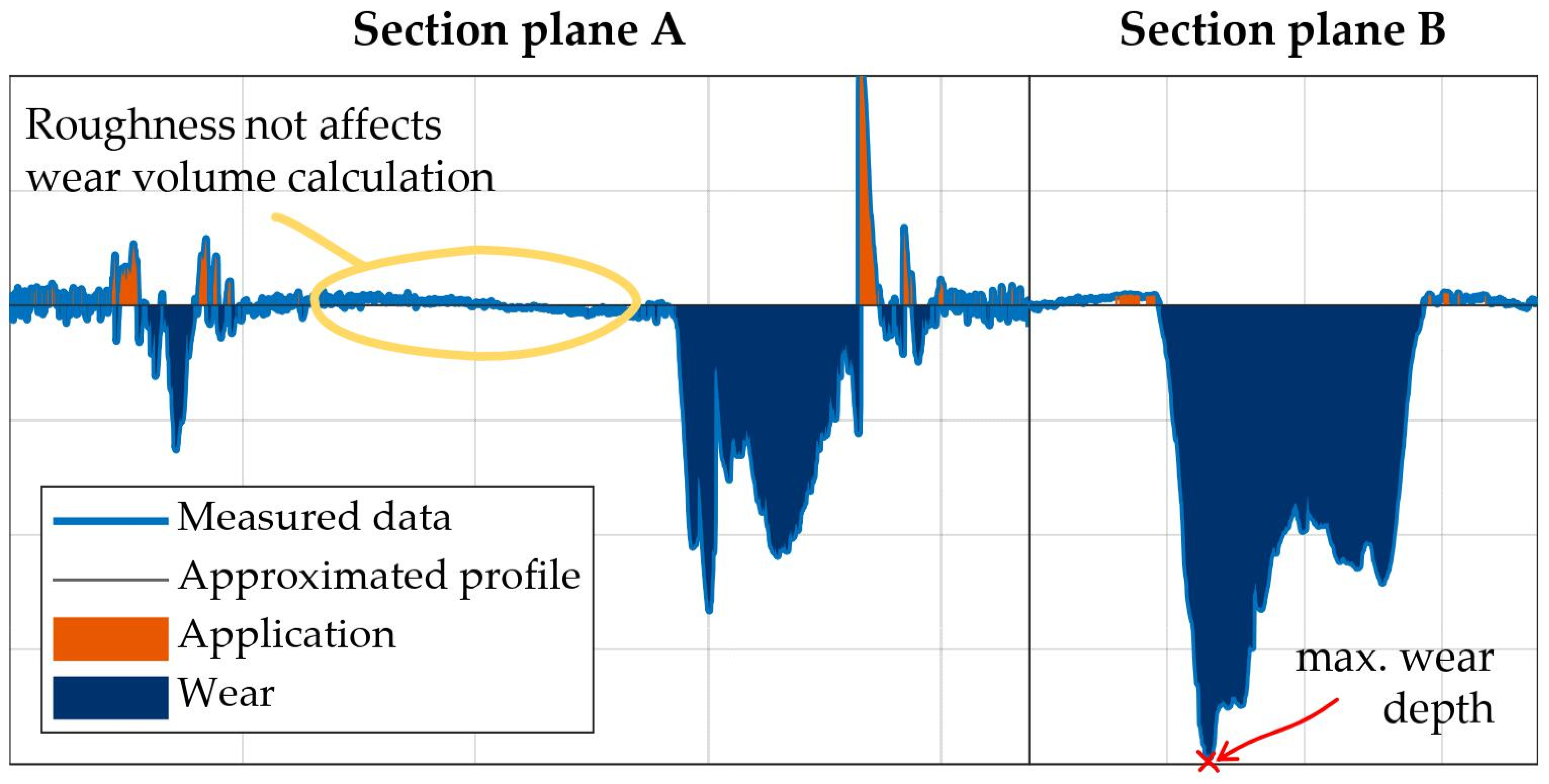
2.2.4. Test Results Evaluation

After completion of the false brinelling test, the test bearings were disassembled into their parts and thoroughly cleaned before the damage could be assessed. The false brinelling damage on the raceways and rolling elements is often very small, and any particles that may have arisen remain in contact and cannot be removed by simple cleaning processes. As a result, it is not possible to determine gravimetric wear and use this as an evaluation criterion. To evaluate the false brinelling damage, light microscope images and surface topographies of the individual marks (see Figure 3) were taken to derive the evaluation criteria described below. Due to the geometry, the marks in the outer ring raceways were the easiest to measure. Therefore, all false brinelling marks of an outer ring were first captured with a light microscope and the length and width of each mark were documented. Then, the surface topographies of the three largest marks were measured with a white light interferometer and evaluated.
After recording the surface topography of a false brinelling mark, the raceway macro geometry was removed. Then, an approximated plane that described the surface of the undamaged raceway was generated. The volumes below this plane were then summarized, whereby roughness in undamaged areas was not considered as having contributed wear volume when evaluating the wear volume of the marks. In addition, the deepest point of the surface below the approximated profile plane, i.e., the maximum wear depth, was determined (see Figure 4).
These results were then averaged over the three largest marks of a bearing outer ring to provide the “average wear volume” and the “averaged maximum wear depth” results as objective evaluation criteria of the test. Based on these two evaluation criteria, the influence of different lubricants on the false brinelling behavior could be clearly identified, whereby both values usually correlated well with each other. Therefore, only the average wear volumes are presented in this paper.
In addition, a subjective evaluation of the degree of corrosion was undertaken. In the case of severe corrosion, corrosive particles that had developed remained in the contact area or as applications on the surfaces. This could lead to misjudgments when considering the objective evaluation criteria alone. These applications are especially harmful to the bearing service life in rotating operation, as very high local pressures occur here.

2.3. Sample Materials

To find out what influence the base oil viscosity and the resulting rheological properties had on the damage development under false brinelling conditions for chemically identical lubricants, model greases were produced with a PAO base oil with three viscosity grades (ν40 = 30/70/110 cSt) and two different thickener types (Li-12-OH-stearate and diurea). To consider a polar base oil type, model greases were also sampled with three different esters (dioctyl sebacate, trimethylolpropane, trimelitic acid ester) and both thickener types. These model greases were set to consistency class NLGI 2 for comparability.
To explore the influence of the grease consistency on the false brinelling damage, additional model greases were produced with a higher viscosity (ν40 = 110 cSt) and a lower viscosity PAO (ν40 = 30 cSt) with two thickeners and NLGI class 1. All model greases were only alloyed with a phenolic antioxidant additive (0.5%) to prevent premature aging. No other additives were added. Table 3 summarizes all the investigated model greases. At least four false brinelling tests were carried out with each model grease at room temperature and −39 °C and evaluated regarding the wear volume.

3. Discussion of Experimental Results

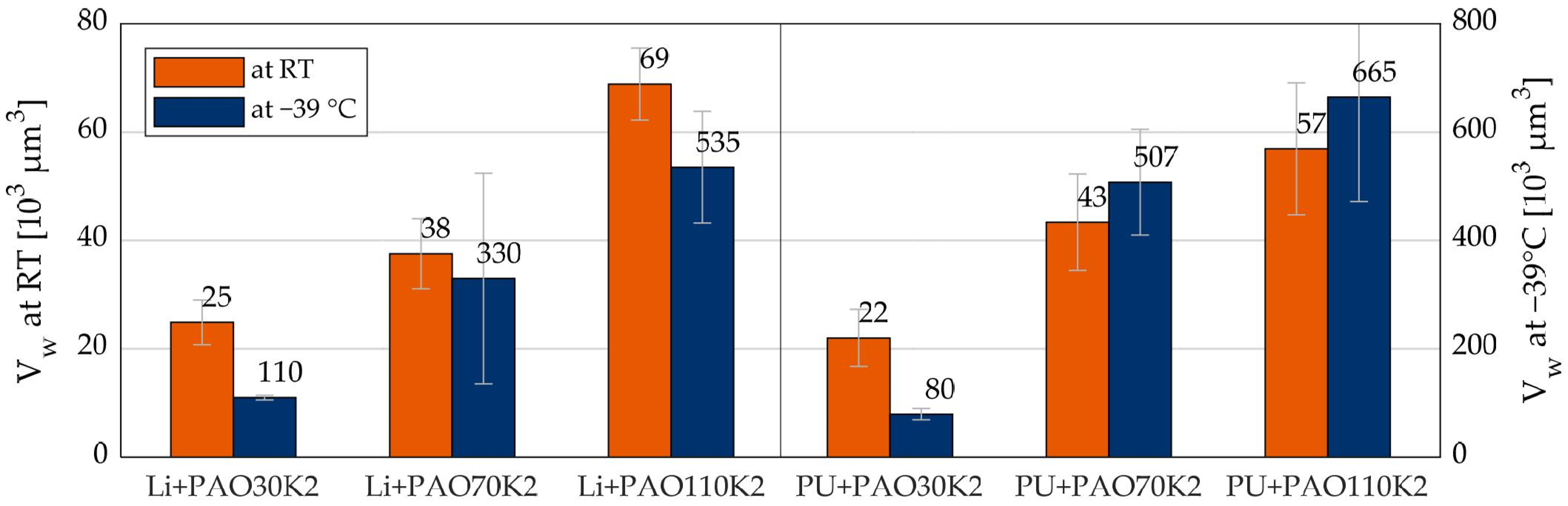
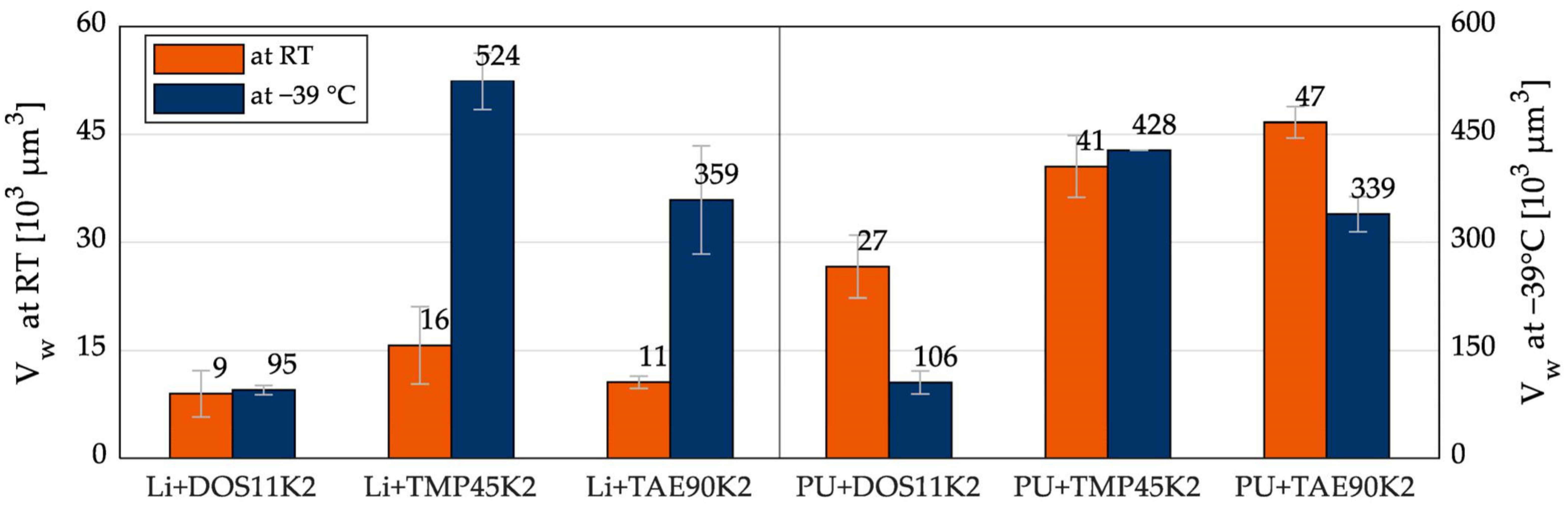
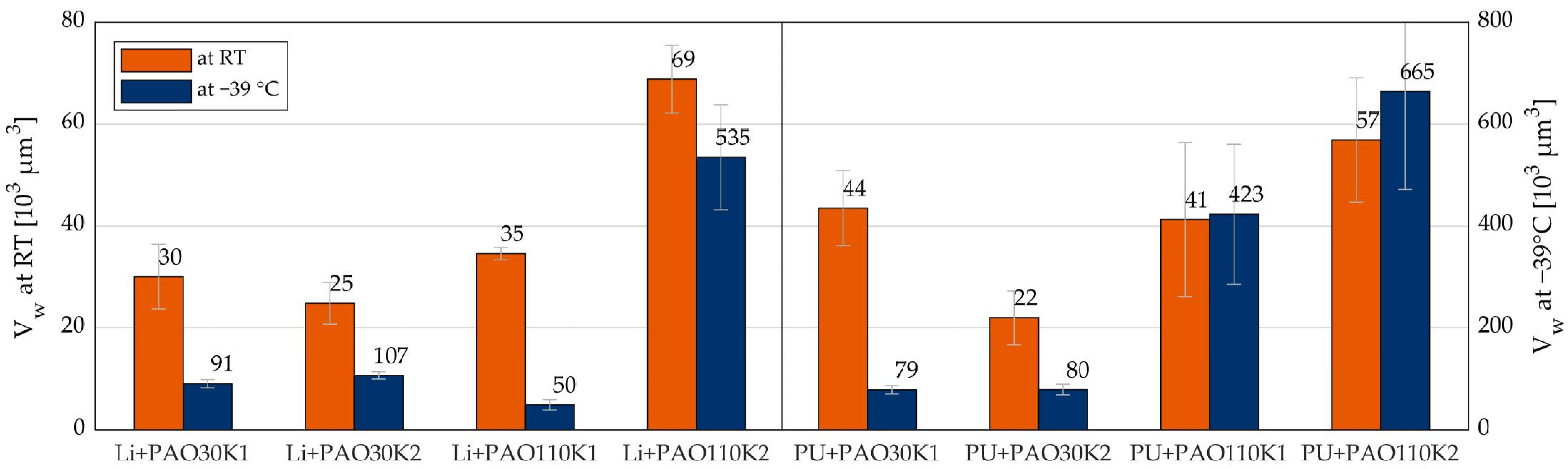
3.1. Influence of the Base Oil Viscosity and Type and the Grease Consistency Class

Figure 5 shows the results of the false brinelling bearing tests, with orange bars representing the results at room temperature (RT) on the left y-axis and blue bars representing the results at −39 °C on the right y-axis. The bars represent the mean values of the wear volumes in 103 μm3 for each test series. The error bars of the bar chart serve as a standard deviation for each test series. It should be noted that the scaling of the y-axes differs by a factor of 10. From this, it can be directly seen that the false brinelling damage was significantly greater at the low temperature than at room temperature. This was particularly due to the change in rheological properties and oil separation as a function of temperature. With decreasing temperature, the viscosity of the base oil and the shear viscosity of the grease itself increased. In addition, the oil separation decreased such that at low temperatures, the availability of the lubricant in contact was reduced. Moreover, at both operating temperatures, a clear dependence of the damage level on the base oil viscosity could be observed. Although only the oil viscosities at 40 °C and not at the respective operating temperatures were compared here, it became clear that a reduction in the base oil viscosity led to a reduction in the false brinelling damage. However, this dependence was not clearly visible with different base oil types (see Figure 6). The model greases with TMP, for example, showed a higher degree of damage at −39 °C than greases with TAE (ν40 = 90 cSt) despite the lower base oil viscosity (ν40 = 45.6 cSt). This could have been due to the chemistry or the crystallization and wetting behavior, as well as the lower oil separation at low temperatures (see Section 3.3).
Figure 7 compares the results of the false brinelling tests with model greases of NLGI classes 1 and 2. The comparison shows a significant reduction in the wear volumes at both the low and room temperatures with the model greases with a higher viscosity base oil (ν40 = 110 cSt) and lower NLGI class. Meanwhile, a decreasing consistency of the model greases with a lower-viscosity base oil (ν40 = 30 cSt) led to an increase in the wear volumes at room temperature. At the low temperature, the results were at a comparable level. This suggests that with the lower-viscosity base oil, the lubricant supply of the contact was comparable to the two greases of NLGI classes 1 and 2.
Some model greases showed an unusually high standard deviation of results, especially at the low temperature. This could have been caused by corrosive particles that remained in the damaged area and distorted the surface measurement.

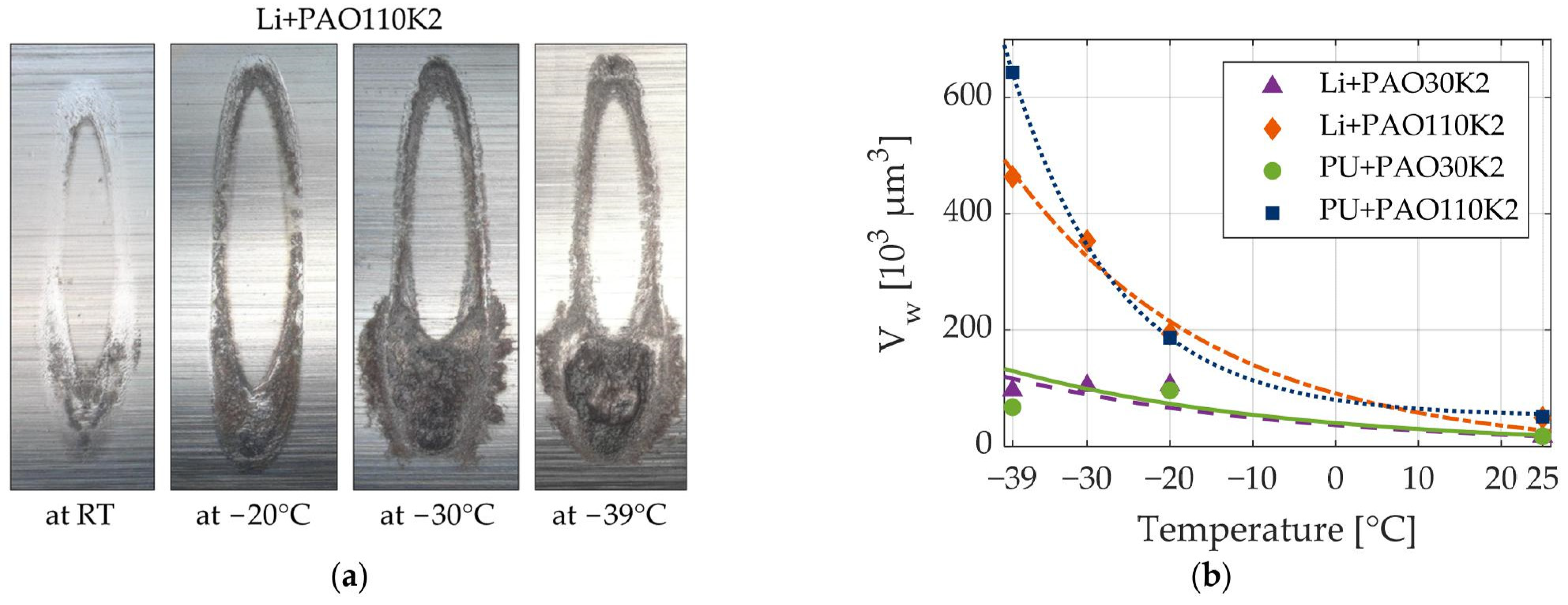
3.2. Influence of Temperature

To analyze the temperature influence more precisely, additional test series were carried out with the lithium soap and urea greases based on PAO with ν40 = 30 cSt and ν40 = 110 cSt at −20 °C and −30 °C (only Li greases). Figure 8a presents exemplary wear patterns observed at different temperatures for the model grease Li+PAO110K2. At RT, a distinct elliptical polished zone was evident, accompanied by the worn region. Upon reducing the temperature to −20 °C, the elliptical zone experienced nearly complete degradation. Subsequently, as the temperature further decreased, the extent of wear progressively intensifies. Notably, at −30 °C and −39 °C, a damaged region and the surrounding zone demonstrated signs of corrosion. The determined wear volumes are summarized in Figure 8b.
For each model, grease trend lines of the wear volumes as a function of operating temperature were created with an exponential function Vw (θ) = a − eb−θ. The damage with the model greases with higher viscosity base oil (ν40 = 110 cSt) increased significantly more with decreasing temperature. The regression coefficient b was two (Li+PAO110K2) or three times (PU+PAO110K2) as high as for the greases with a lower-viscosity base oil (ν40 = 30 cSt). This means that greases with a higher-viscosity base oil were more temperature-dependent than greases with a lower-viscosity base oil. In Section 3.3 and Section 3.5, the changes in rheological properties and oil separation are shown as a function of temperature. As the temperature decreased, the viscosity of the base oil and the shear viscosity of the grease itself increased. In addition, the oil separation decreased such that at low temperatures, the availability of the lubricant in contact was reduced.

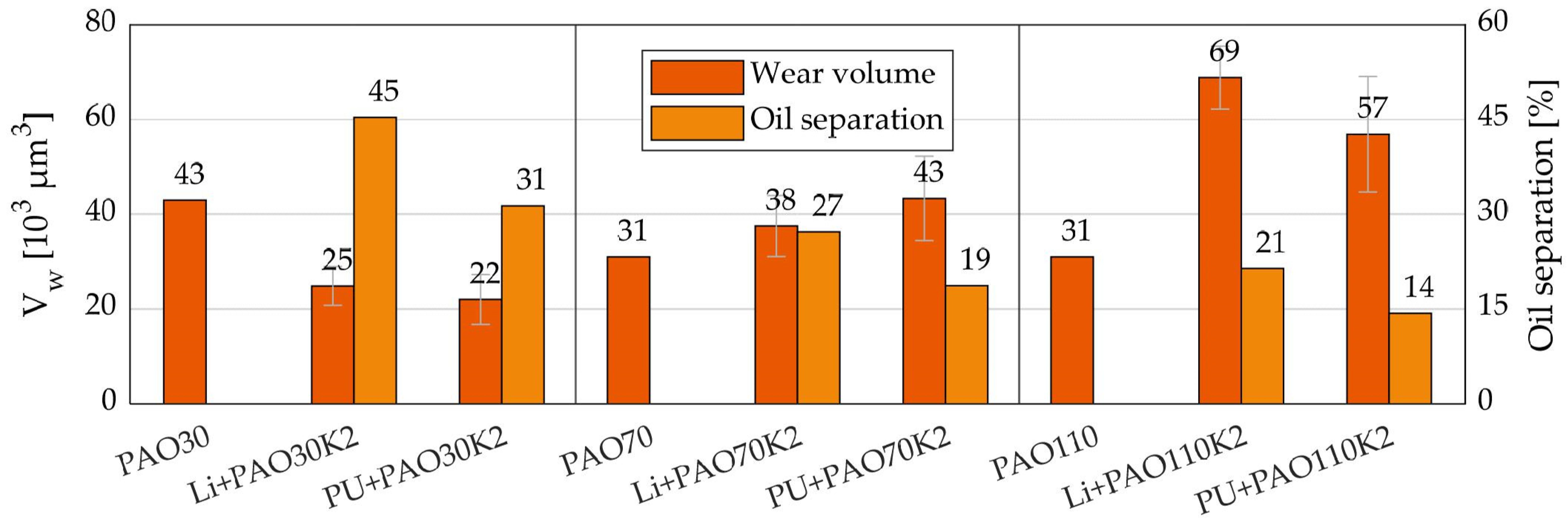
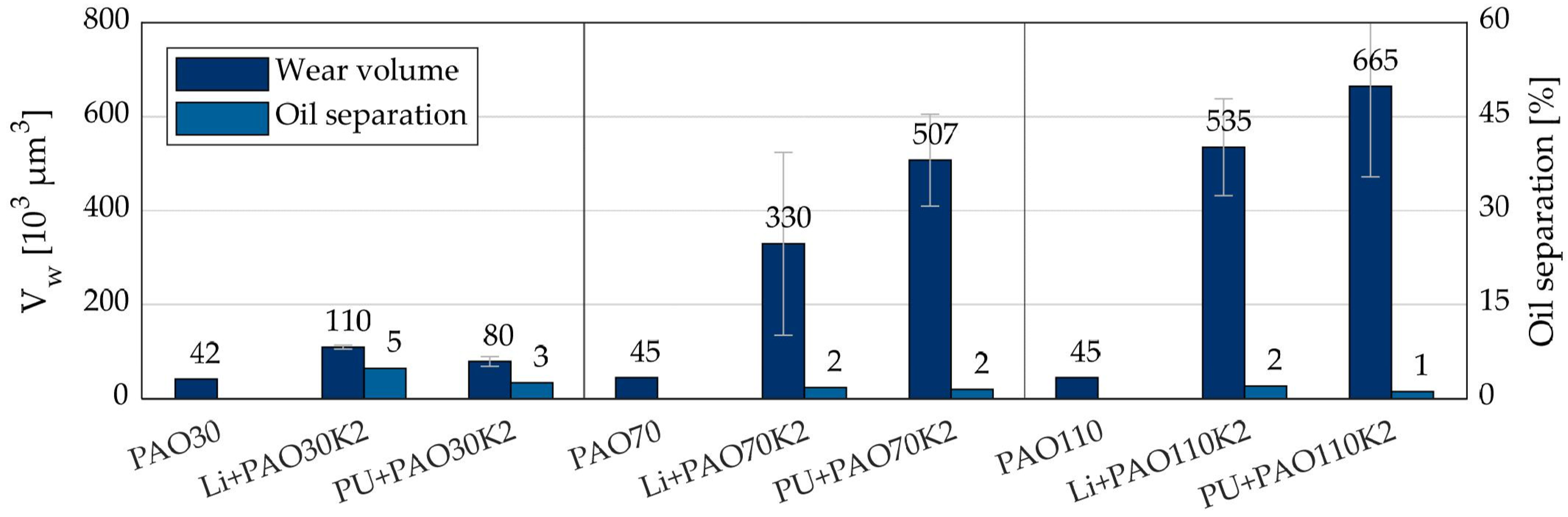
3.3. Influence of Oil Separation

It was observed that pure oil lubrication results in less false brinelling damage compared with grease-lubricated bearings under the same test conditions [9,10,11,16]. This suggests that the presence of lubricating oil may significantly influence the damage mechanisms during false brinelling. To examine the effect of oil separation on the false brinelling behavior of greases, oil separation tests were conducted on the tested greases at room temperature (RT), −20 °C, and −39 °C using the filter paper ring house method of Robert Bosch GmbH. These tests involved filling a stainless-steel ring with the grease to be tested and pressing one of the grease surfaces onto a filter paper on a flat glass plate. The amount of oil released by the grease during the test period (48 h in this case) was quantified by weighing the filter paper. The results of the oil separation tests at the three temperatures are shown in Figure 9a as a bar chart in percent from the initial grease weight. The oil separation was highly dependent on temperature, with lower temperatures resulting in lower oil separation [17]. In addition, greases with higher viscosity base oils, diurea thickeners, and higher consistency class tended to have lower oil separation.
When the results of the oil separation tests were compared with the wear volumes determined from the false brinelling tests (as shown in Figure 9b), a strong non-linear dependence of false brinelling damage on oil separation was observed. In particular, very low oil separation led to significantly increased damage. While high oil separation is desirable for reducing false brinelling damage, it may not be optimal for achieving the longest possible grease operating life, which requires a moderate and consistent release of oil over the service life [17].

3.4. Sample Tests with Base Oils

In order to evaluate the effect of the base oils independently of the oil separation of the model greases, sample tests were carried out with pure base oils on the false brinelling test rig. Due to time constraints, only the PAO base oils were examined in this series of tests. In addition, only one test per base oil was performed at room temperature and −39 °C. The results were not statistically validated.
In Figure 10 and Figure 11, the results of the false brinelling tests with pure base oils are compared with the results of the corresponding model greases (with Li- and PU-thickener). Considering only the results with the base oils, the wear volumes at −39 °C were higher with the PAO [70 cSt/110 cSt] than at RT. With the PAO [30 cSt], the results were at the same level at both temperatures. It was observed that at −39 °C, the wear was mainly concentrated in the areas with high slip, with greater wear depths and stronger corrosion. At RT, pronounced zones of influence with smoothing of the surfaces were observed, where wear also occurred. This was very distinct for PAO [30 cSt], leading to the high value of the wear volume at RT.
Especially at −39 °C, and thus, very low oil separation rates, the differences between the results with the pure base oils and the corresponding model greases were huge. The wear volumes with the model greases were in some cases greater by a factor of 10. In the case of PAO [30 cSt], the wear volumes with greases were only twice as high as in the oil tests, which was due to the better flow properties and slightly higher oil separation.
At RT, with the PAO [70 cSt/110 cSt], it was also determined that larger wear volumes were achieved with the corresponding model greases than with the pure base oil tests. In both test series based on the Li- and the PU thickener, it was observed that the oil separation decreased with increasing base oil viscosity, and this led to an increase in false brinelling damage. All these results suggest that a good supply of oil to the contacts was essential to reduce false brinelling damage.

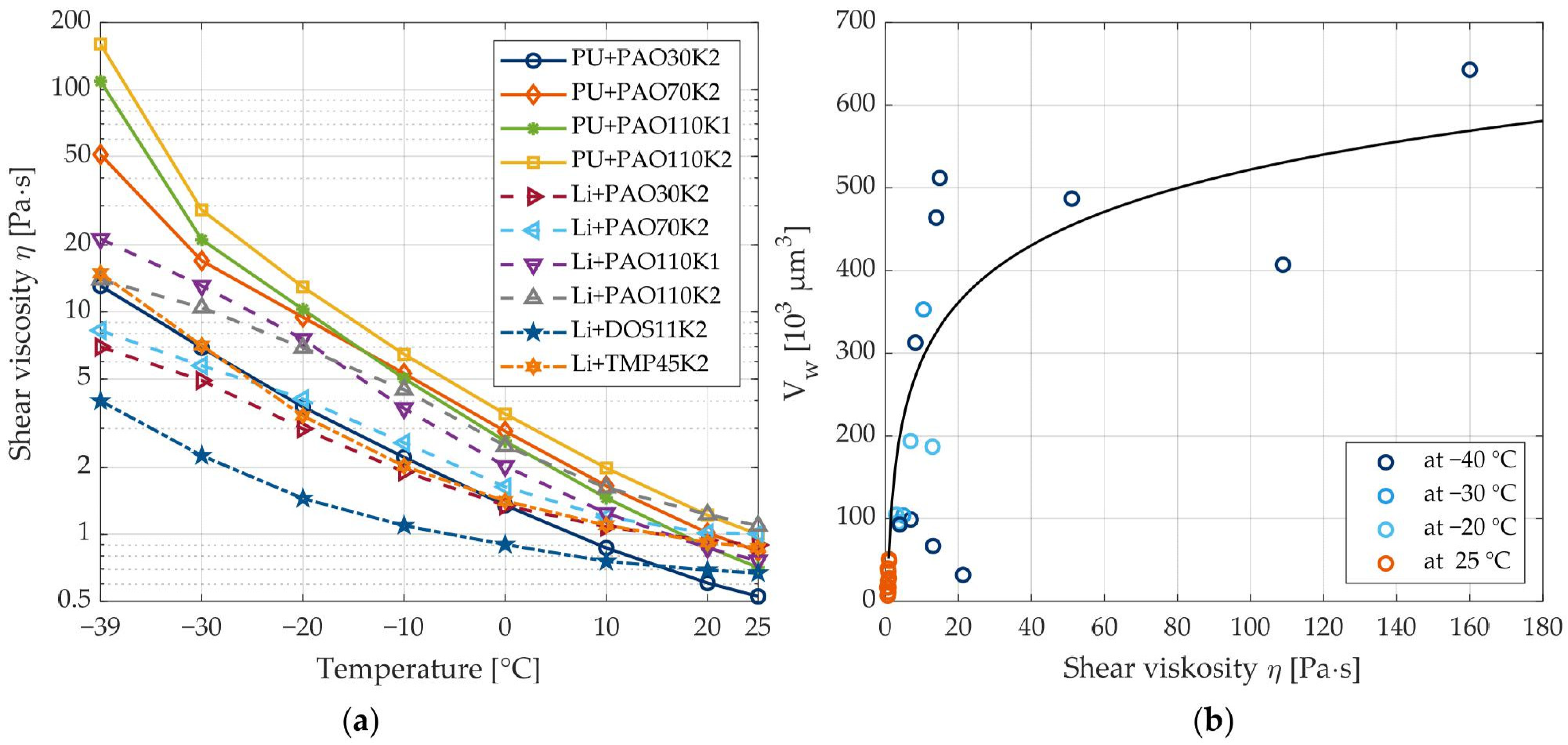
3.5. Influence of Shear Viscosity

To evaluate the flowability of the model greases at various temperatures and compare them to false brinelling damage, shear tests were performed on a cone–plate rheometer at a constant shear rate of 2000 s−1 and discrete temperature steps from −40 °C to 25 °C. The results of these tests, which were used to determine the shear viscosity, are shown in Figure 12a. The results show that the shear viscosity increased with decreasing temperature for all greases. This effect was particularly pronounced for urea greases. This led to significant differences in the shear viscosities of the individual model greases at −40 °C. The model grease with the lowest base oil viscosity (Li+DOS11K2) had the lowest shear viscosity at −40 °C, while the urea grease with the highest base oil viscosity (PU+PAO110K2) had the highest shear viscosity at this temperature. By comparison, the lithium soap grease (Li+PAO110K2) had a 12 times lower shear viscosity at the same temperature and with the same oil.
Figure 12b shows the wear volume resulting from the false brinelling tests as a function of the shear viscosity for all the model greases and operating temperatures. These results indicate that as the shear viscosity increased, the damage caused by false brinelling tended to increase as well. The regression curve derived using a logarithmic approach (with a coefficient of determination of 0.94) illustrates this relationship more clearly. A linear representation also shows that the influence of shear viscosity on false brinelling damage was more pronounced at low shear viscosities.

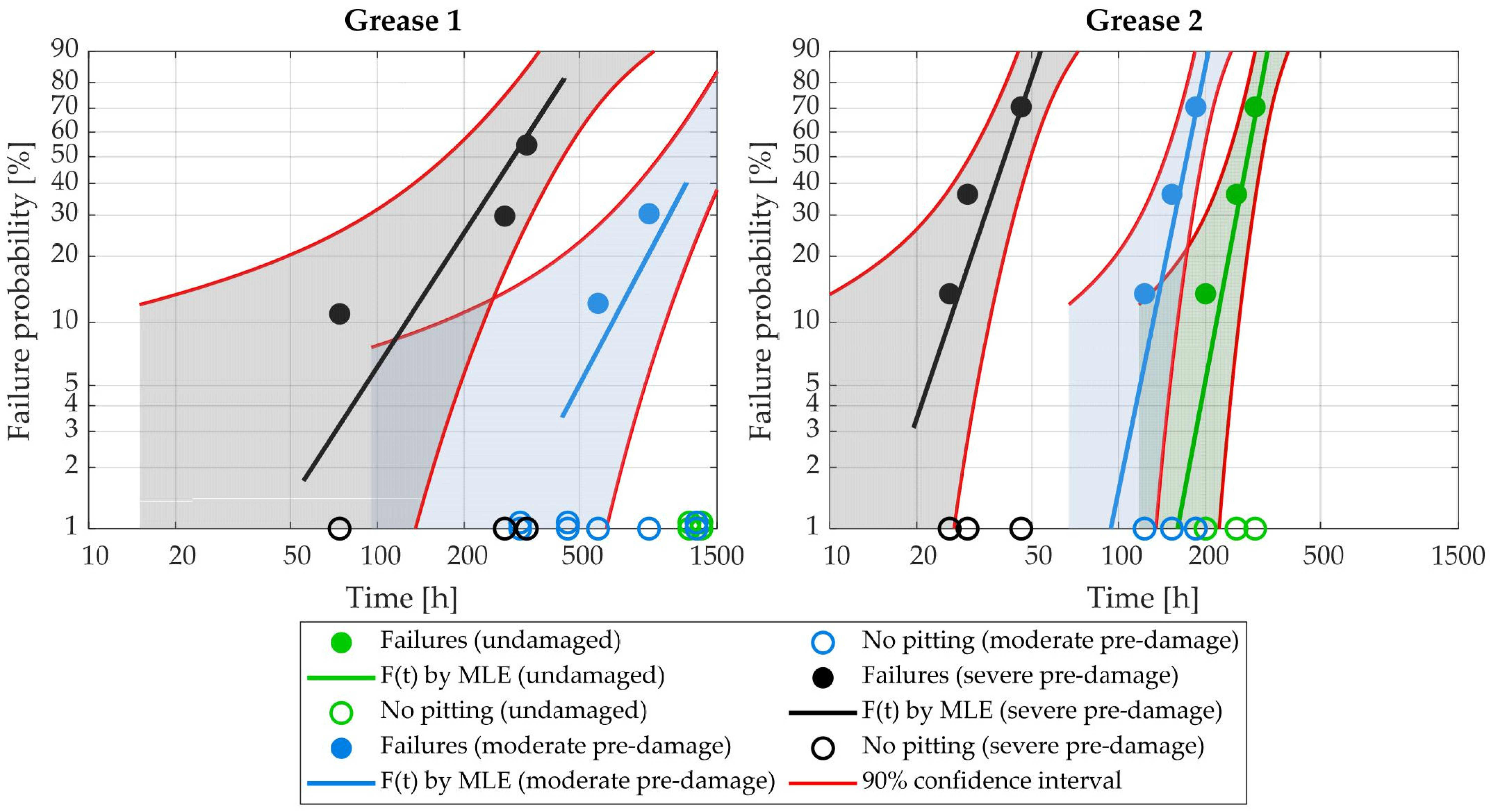
3.6. Durability Test Results

Fatigue tests were conducted to investigate the impact of false brinelling damage on the service life of angular contact ball bearings in rotating operation. The bearings used in the tests were pre-damaged on a false brinelling bearing test rig and then mounted in a modified FE8 test head. Previous research showed that the service life of oil-lubricated rolling bearings with false brinelling damage can be significantly reduced [18], with severe pre-damage resulting in a reduction from L10 h,exp = 2500 h to only 150 h. In this study, grease-lubricated bearings were used and were not cleaned after pre-damage due to false brinelling, with any resulting wear particles left in the bearing to simulate real-life conditions. The FE8 life tests were performed with an axial load of 18 kN (C/P = 1.49) at a rotational speed of 1000 rpm and 80 °C, with a maximum Hertzian pressure in the contact of 3202 MPa. The test conditions were chosen to generate mixed friction conditions to create fatigue damage in a moderate time. The durability tests were conducted with two different industrial greases (with the same base oil viscosity and NLGI class) with two levels of false brinelling damage and with undamaged bearings. The moderate false brinelling damage level was defined as an average wear volume of approx. 55 × 103 µm3, while the severe pre-damage level was defined as a wear volume of approx. 275 × 103 µm3. The results of the FE8 service life tests were evaluated using a Weibull mesh, with the bearings that failed due to pitting damage shown as dots and those without pitting damage represented by circles on the x-axis in Figure 13. The black, blue, and green lines represent the failure lines F(t) according to the maximum likelihood estimate (MLE) method, which also includes bearings that did not fail. At the intersection of the failure line with the 10% failure probability, the experimentally determined bearing service life L10 h,exp can be read. In the case of undamaged bearings lubricated with industrial grease 1, no failures occurred within the planned maximum test duration of 1000 h, making a Weibull evaluation impossible for these tests.
Table 4 summarizes the results, clearly demonstrating that different levels of false brinelling damage can significantly reduce the bearing life, with industrial grease 2 showing a service life that was approximately 4 to 5 times shorter than industrial grease 1 at the same damage level. In addition, it was observed for both greases that the bearing life was shorter by a factor of about 5 in the case of severe pre-damage (defined by a wear volume of approx. 275 × 103 µm3) than in the case of moderate pre-damage (defined by a wear volume of approx. 55 × 103 µm3).

4. Conclusions

False brinelling is a wear phenomenon that can occur in stationary rolling bearings subjected to dynamic loads and/or oscillating movements with very small amplitudes. It can lead to increased noise emissions during operation and reduced bearing service life. The use of a suitable lubricant is an effective way to prevent or minimize false brinelling damage. This paper presents a novel false brinelling test rig and test method that provides results that are reproducible and can differentiate between different lubricants. Using this method, various model greases were tested. All model greases were only alloyed with a phenolic antioxidant additive (0.5%) to prevent premature aging. Other additives were not used in this study in order to investigate the influences of the rheological properties independently of additives.
  • The results suggest that the presence of lubricant in the rolling element raceway contact was necessary for a suitable lubricating grease to protect the surfaces with its additives.
  • A reduction in the base oil viscosity led to a reduction in the false brinelling damage. This could be shown very clearly based on results in tests on model greases with chemically identical PAO base oils with different viscosity. However, when other chemically different base oil types (e.g., esters) were compared, such a tendency among PAO oils was not observed in all cases, e.g., bearings with Li+TMP45 received higher damage than with Li+TAE90 even though the second has a higher base oil viscosity. The authors suggest that this behavior could have been caused by other factors, such as chemical properties (e.g., the polarity of oils) or wetting behavior, that were not investigated in the current work.
  • A comparison of the model greases of different NLGI classes and base oil viscosities indicated that selecting a higher-viscosity base oil and lower NLGI class could lead to significant reductions in wear volumes at both low and room temperatures.
  • Lower oil separation led to increased damage. While high oil separation can reduce false brinelling damage, a moderate and consistent release of oil over the service life is optimal for achieving the longest possible grease operating life.
  • The results of the shear tests on various model greases showed that the shear viscosity of the greases increased with decreasing temperature. A lower shear viscosity of the grease led to improved flow properties, and thus, decreased the level of false brinelling damage.
  • The damage level was significantly higher at low temperatures due to changes in rheological properties and oil separation.
  • The results also demonstrated the extent to which different levels of false brinelling damage can reduce bearing life with different greases.
In conclusion, the findings of this study offer valuable insights that can be utilized to develop specific lubricating greases that are capable of significantly reducing false brinelling damage. Consequently, this leads to decreased breakouts on bearing raceways and rolling elements, as well as a reduction in wear particles present in the grease. These outcomes positively contribute to extending the overall lifetime of the bearings. Additionally, the industry has responded favorably to the presented test method, emphasizing its effectiveness in evaluating greases and its potential for improving the performance and durability of rolling bearings.

Author Contributions

Conceptualization, D.B. and C.S.; methodology, C.S.; software, S.T.; validation, C.S.; formal analysis, S.T.; investigation, S.T.; resources, C.S. and S.T.; data curation, S.T.; writing—original draft preparation, S.T.; writing—review and editing, C.S. and D.B.; visualization, S.T.; supervision, D.B.; project administration, D.B.; funding acquisition, C.S. and D.B. All authors have read and agreed to the published version of the manuscript.

Funding

This research project was carried out in the framework of the industrial collective research program (IGF no. 19786 BR). It was supported by the Federal Ministry for Economic Affairs and Climate Action (BMWK) through the German Federation of Industrial Research Associations (AiF) based on a decision taken by the German Bundestag. The authors would like to thank the Industrial collaborative research (IGF) for the funding and the Research Association for Drive Technology (FVA) for the support during the project period (FVA 540 III).

Data Availability Statement

The data presented in this study are available from the corresponding author upon request.

Conflicts of Interest

The authors declare no conflict of interest.

References

  1. Almen, J.O. Lubricants and False Brinelling of Ball and Roller Bearings. Mech. Eng. 1937, 59, 415–422. [Google Scholar]
  2. Schadow, C. Stillstehende Fettgeschmierte Wälzlager unter Dynamischer Beanspruchung. (Standstill Grease-Lubricated Rolling Bearings under Dynamic Load). Ph.D. Thesis, Otto-von-Guericke-Universität Magdeburg, Shaker Verlag, Aachen, Germany, 2016. [Google Scholar]
  3. Bosse, H.; Müller, F. Schmierungsverhalten bei oszillierenden Gleit- und Wälzbewegungen (Lubrication Behavior in Oscillating Sliding and Rolling Motions); Final Report to FVA Research Project 315 II; FVA: Frankfurt, Germany, 2003; Volume 714, Available online: https://www.tib.eu/en/search/id/TIBKAT:524126976/Schmierungsverhalten-bei-oszillierenden-Gleit-und?cHash=ee3ed44dabd8389a846005ee54ffb7ad (accessed on 24 May 2023).
  4. Fritzsche, R. Beschädigung eines Radlagers beim Pkw-Transport auf einem Lkw. (Damage to a wheel bearing during car transport on a truck). ATZ 2019, 121, 58–63. [Google Scholar]
  5. Fallahnezhad, K.; Brinji, O.; Desai, A.; Meehan, P.A. The influence of different types of loading on false brinelling. Wear 2019, 440–441, 203097. [Google Scholar] [CrossRef]
  6. Mannens, R.; Trauth, D.; Falker, J.; Brecher, C.; Klocke, F. Analysis of spindle bearing load with regard to the false brinelling effect caused by machine hammer peening. Int. J. Adv. Manuf. Technol. 2018, 95, 3969–3976. [Google Scholar] [CrossRef]
  7. Grebe, M. False-Brinelling und Stillstandsmarkierungen bei Wälzlagern: Schäden bei Vibrationsbelastung oder Kleinen Schwenkwinkeln (False Brinelling and Standstill Marks in Rolling Bearings: Damage under Vibration Load or Small Pivot Angles), 1st ed.; Expert Verlag: Renningen, Germany, 2017; ISBN 9783838551609. [Google Scholar]
  8. Schwack, F. Untersuchungen zum Betriebsverhalten Oszillierender Wälzlager am Beispiel von Rotorblattlagern in Windener-Gieanlagen. (Investigations into the Operating Behavior of Oscillating Rolling Bearings Using the Example of Rotor Blade Bearings in Wind Turbines). Ph.D. Thesis, Gottfried Wilhelm Leibniz Universität, Hannover, Germany, 2020. [Google Scholar]
  9. Schadow, C. Stillstehende fettgeschmierte Wälzlager unter dynamischer Belastung (Standstill Grease-Lubricated Rolling Bearings under Dynamic Load); Final Report to FVA Research Project 540 I; FVA: Frankfurt, Germany, 2010; Volume 951, Available online: https://www.tib.eu/en/search/id/TIBKAT:677756917/False-Brinelling-Stillstehende-fettgeschmierte?cHash=553cbd028f3c4ae0cd30c74565c592ee (accessed on 24 May 2023).
  10. Schadow, C. Stillstehende fettgeschmierte Wälzlager unter dynamischer Belastung (Standstill Grease-Lubricated Rolling Bearings under Dynamic Load); Final Report to FVA Research Project 540 II; FVA: Frankfurt, Germany, 2018; Volume 1268, Available online: https://www.tib.eu/en/search/id/TIBKAT:1026687241/Stillstehende-fettgeschmierte-W%C3%A4lzlager-Stillstehende?cHash=3d5b2af976990286dbdfb935d189a68e (accessed on 24 May 2023).
  11. Tetora, S. Stillstehende fettgeschmierte Wälzlager unter dynamischer Belastung (Standstill Grease-Lubricated Rolling Bearings under Dynamic Load); Final Report to FVA Research Project 540 III; FVA: Frankfurt, Germany, 2022; Volume 1494, Available online: https://www.tib.eu/en/search/id/TIBKAT:1831095963/Stillstehende-fettgeschmierte-W%C3%A4lzlager-stillstehende?cHash=d3ff9311c29c42984cee58451ddc94b2 (accessed on 24 May 2023).
  12. ASTM D4170-16; Test Method for Fretting Wear Protection by Lubricating Greases. ASTM International: West Conshohocken, PA, USA, 2016. [CrossRef]
  13. ASTM D7594-19; Test Method for Determining Fretting Wear Resistance of Lubricating Greases under High Hertzian Contact Pressures Using a High-Frequency, Linear-Oscillation (SRV) Test Machine. ASTM International: West Conshohocken, PA, USA, 2019. [CrossRef]
  14. Griesheimer, S. Einflussfaktoren auf die Entstehung von Stillstandsmarkierungen. (Influencing Factors on the Formation of Standstill Markings). Diploma Thesis, Hochschule Mannheim, Mannheim, Germany, 2007. [Google Scholar]
  15. Pittroff, H. Riffelbildung bei Wälzlagern infolge Stillstandserschütterungen. (Ripple Formation in Rolling Bearings due to Standstill Vibrations). Ph.D. Thesis, TU München, München, Germany, 1961. [Google Scholar]
  16. Januszewski, R.; Brizmer, V.; Kadiric, A. Effect of Lubricant Properties and Contact Conditions on False Brinelling Damage. Tribol. Trans. 2023, 66, 350–363. [Google Scholar] [CrossRef]
  17. Lugt, P.M. Grease Lubrication in Rolling Bearings; Wiley: Chichester West Sussex, UK, 2013; ISBN 9781118353912. [Google Scholar]
  18. Schadow, C.; Tetora, S.; Bartel, D. Folgeschäden durch False-Brinelling in Radlagern durch geeignete Schmierfette vermei-den. (Consequential damage avoid by false brinelling in wheel bearings by using suitable lubricating greases). In Experten-Forum Powertrain: Reibung in Antrieb und Fahrzeug 2020; Liebl, J., Ed.; Springer: Berlin/Heidelberg, Germany, 2021; pp. 15–29. ISBN 978-3-662-63607-7. [Google Scholar]
Figure 1. False brinelling marks for an angular contact ball bearing 7205 (a,b) and 7312 (c): rolling distance < width of contact ellipse (a), rolling distance > width of contact ellipse (b), and rolling distance >> width of contact ellipse (c).
Lubricants 11 00279 g001
Figure 2. False brinelling test rig for oscillating movements and dynamic radial and axial loads.
Lubricants 11 00279 g002
Figure 3. Light microscope image (a) and surface topography (b) of a false brinelling wear mark.
Lubricants 11 00279 g003
Figure 4. Surface profiles in the length and width directions.
Lubricants 11 00279 g004
Figure 5. Variation of base oil viscosity and type with PAO based greases.
Lubricants 11 00279 g005
Figure 6. Variation of base oil viscosity and type ester based greases.
Lubricants 11 00279 g006
Figure 7. Variation with the grease consistency class.
Lubricants 11 00279 g007
Figure 8. Exemplary wear marks at different temperatures (a); the temperature dependence of wear volume (b).
Lubricants 11 00279 g008
Figure 9. Oil separation at different temperatures after 48 h (a), oil separation vs. wear volume (b).
Lubricants 11 00279 g009
Figure 10. Sample false brinelling tests with pure base oils and oil separation of model greases at room temperature.
Lubricants 11 00279 g010
Figure 11. Sample false brinelling tests with pure base oils and oil separation of model greases at −39 °C.
Lubricants 11 00279 g011
Figure 12. Shear viscosity of model greases (a) and the wear volume dependence on shear viscosity (b).
Lubricants 11 00279 g012
Figure 13. Weibull evaluation of FE8 durability tests.
Lubricants 11 00279 g013
Table 1. Parameter of false brinelling test rig.
ParameterValue
Motor rotational speed0 to 1500 rpm
Motor pivot frequency0 to 20 Hz
Pivot angle±0.025° to ±2.0°
Radial and axial load (static)0 to 15 kN
Radial and axial load (dynamic)2 to 5 kN
Radial and axial load frequency0 to 50 Hz
Temperature−40 °C to +40 °C
LubricantsGrease, oil
Bearing typeAngular contact bearing (7205),
tapered roller bearing 32005-X
Table 2. Standard parameter of false brinelling test.
ParameterValue
Load scenarioAxial and radial static load + dynamic radial load + pivot movement
Load zone ψ180°
Average load C0/P010
Load amplitude ΔP0/P0±25%
Load frequency fL8 Hz
Pivot angle β±0.25°
Pivot frequency fβ 5 Hz
Operating temperature θ−40 °C to +40 °C
Oscillating cycles0.5 Mio
Bearing typeAngular contact bearing (7205)
Table 3. Model greases.
AbbreviationThickener Type
(Thickener Content)
Base Oilν40
[cSt]
Worked Penetration
[mm/10]
Li+PAO30K2Li-12-OH-stearate (10%)Poly alpha olefin30275
Li+PAO70K2Li-12-OH-stearate (10%)Poly alpha olefin70269
Li+PAO110K2Li-12-OH-stearate (9.5%)Poly alpha olefin110279
PU+PAO30K2Diurea (13.7%)Poly alpha olefin30275
PU+PAO70K2Diurea (22.9%)Poly alpha olefin70280
PU+PAO110K2Diurea (14.1%)Poly alpha olefin110273
Li+DOS11K2Li-12-OH-stearate (9%)Dioctyl sebacate11.6280
Li+TMP45K2Li-12-OH-stearate (7.5%)Trimethylolpropane45.6270
Li+TAE90K2Li-12-OH-stearate (9.5%)Trimelitic acid ester90265
PU+DOS11K2Diurea (16%)Dioctyl sebacate11.6276
PU+TMP45K2Diurea (16%)Trimethylolpropane45.6270
PU+TAE90K2Diurea (14%)Trimelitic acid ester90278
Li+PAO30K1Li-12-OH-stearatePoly alpha olefin30327
Li+PAO110K1Li-12-OH-stearate (7%)Poly alpha olefin110322
PU+PAO30K1Diurea (12%)Poly alpha olefin30325
PU+PAO110K1Diurea (11.7%)Poly alpha olefin110326
Table 4. Results of the Weibull evaluation.
GreaseGrease 1Grease 2
Pre-damageSevereModerateSevereModerateUndamaged
Experimentally determined service life L10 h,exp125.5 h651.9 h25.9 h131.6 h218.2 h
Disclaimer/Publisher’s Note: The statements, opinions and data contained in all publications are solely those of the individual author(s) and contributor(s) and not of MDPI and/or the editor(s). MDPI and/or the editor(s) disclaim responsibility for any injury to people or property resulting from any ideas, methods, instructions or products referred to in the content.

