Article

A Numerical Investigation of the Effects of Groove Texture on the Dynamics of a Water-Lubricated Bearing–Rotor System

1
College of Mechanical and Electrical Engineering, Hohai University, Changzhou 213022, China
2
Department of Precision and Microsystems Engineering, Delft University of Technology, 2628 CD Delft, The Netherlands
*
Author to whom correspondence should be addressed.
Lubricants 2023, 11(6), 242; https://doi.org/10.3390/lubricants11060242
Submission received: 21 April 2023 / Revised: 18 May 2023 / Accepted: 29 May 2023 / Published: 31 May 2023

Abstract

:
This paper aims to investigate the combined effects of working condition and structural parameters of groove texture on the dynamic characteristics, stability and unbalance response of a water-lubricated hydrodynamic bearing–rotor system to avoid instability and excessive vibration of the rotor. The Navier–Stokes equation, standard K-ε model with enhanced wall treatment and Zwart–Gerber–Belamri cavitation model are considered using the commercial software Fluent to calculate the stiffness and damping coefficients of a groove-textured, water-lubricated bearing based on the dynamic mesh method; the critical mass to express the stability and the unbalance response solved by the fourth order Runge–Kutta method of the rotor are calculated based on dynamic equations. The results indicate that shallower and longer groove textures can improve the direct stiffness along the load direction k y y , weaken the stiffness in the orthogonal direction k x x , improve stability and decrease the unbalance response amplitude of the water-lubricated bearing–rotor system at a greater rotational speed and smaller eccentricity ratio; however, the impact of grooves on damping parameters is not as great as it is on stiffness—there exists an optimum groove width to achieve a best dynamic performance.

1. Introduction

The water-lubricated hydrodynamic journal bearing (WLHB) has gained attention in the area of high-speed spindle systems and marine shafts due to the combined advantages of low power loss, being free of pollution at large rotary speed, good damping and long lifetime. Numerous researches about the static performance [1,2,3,4] and dynamic performance [5] of WLHBs have been carried out based on the Reynolds equation [2,5], Navier–Stokes using the CFD analysis method [1,3,4] or experimental methods [6]. Despite the numerous advantages of water as a lubricant, further researches to improve the load capacity and reduce friction still need to be carried out.
Recently, surface texture has been successfully used in the field of water-lubricated bearings to further improve load capacity and tribological performance [7,8]. However, a higher rotary speed and smaller radial clearance usually adopted in WLHBs easily leads to a reduction in stability and the tendency to unbalance the bearing–rotor system [9]. To avoid instability and excessive vibration of the rotor, the effect of surface texture on water-lubricated bearing–rotor systems should be fully studied.
In the past few years, the effects of shape, size and distribution of textures on the static performance such as friction, wear and carrying capacity of water-lubricated bearings have been thoroughly investigated [7,8,10,11,12,13]. It can be concluded that the wear could be apparently reduced and the bearing capacity can be significantly enhanced with specific structural parameters for different working conditions. The mathematical models adopted usually are the Reynolds equation and Navier–Stokes equations. Cavitation, turbulence or inertia are taken into consideration partially or entirely to account for the mechanisms of textured bearings [14,15,16]. Results show that the Navier–Stokes equations are needed when film heights are in the same order or greater than pocket depth, and convective inertia effects are important [17].
To numerically evaluate the influence of surface texture on the dynamics of a rotor, the dynamic characteristics of the bearings including stiffness and damping coefficients should be determined first, which will then be substituted into dynamic equations [18,19,20,21]. Xie et al. [12] pointed out that speed has a significant influence on the equivalent stiffness. Sharma et al. [19] numerically investigated the influences of a triangular shape texture on the stability and found that lower texture depth is beneficial for direct stiffness and threshold speed. Singh and Awasthi [20] found that using the optimal distribution and aspect ratio could increase the stability apparently. However, it should be noted that for the available researches, the stiffness and damping coefficients being substituted into the dynamic rotor equations are solved by the laminar Reynolds equations.
Recently, some researchers carried out experimental investigations on the effect of texture on the stability of bearing–rotor systems [14,21,22,23] and proved that the vibration of the water-lubricated bearing–rotor system could be apparently reduced by reasonable design of the texture.
However, a comprehensive numerical study to explore how textures affect the stability and unbalance response of the WLHB rotor system based on Navier–Stokes equation considering cavitation, turbulence and inertia has not been undertaken. This research is a follow-up study based on the previous study about static performance of grooved WLHB we made before [7] that aims to fill the gap and investigate the combined influences of working conditions (rotary speed and eccentricity ratio) and structural parameters (width, depth and length of groove texture) on the dynamic characteristics, stability and unbalance response of the water-lubricated hydrodynamic bearing–rotor system used in high-speed spindles.

2. Mathematical Models

2.1. Governing Equations

The groove-textured WLHB is depicted in Figure 1. Half of the bearing is modeled due to its axial symmetry perpendicular to the y-O-x plane along the z axis.
In the present work, the flow behavior is solved by CFD and calculated on the bases of the Navier–Stokes equation for incompressible flow and the isothermal conditions. The mass conservation equation coupled with the momentum conservation equations are as follows [7,24]:
The mass conservation equation is
ρ t + ( ρ u ) x + ( ρ v ) y + ( ρ w ) z = 0
The momentum conservation equation is
t ( ρ v ) + ( ρ v v ) = P + ( τ ) + ρ g   + F
where ρ is the density of the fluid, u ,   v ,   w is the velocity vector, P is the static pressure, τ is the stress tensor, ρ g is the gravitational body force and F is the external body force.
For groove-textured water-lubricated bearings, turbulence and cavitation might occur owning to the low viscosity of water, high rotational speed, large film thickness and divergent region. The standard K-ε model with enhanced wall treatment will be adopted. The equation for the kinetic energy of turbulence and the equation for the dissipation rate are as follows:
k t + u i ¯ k x i = v t [ u i ¯ x j + u j ¯ x i ] u i ¯ x j + x i ( v t σ k k x i ) ε
ε t + u i ¯ ε x i = C 1 ε ε k v t [ u i ¯ x j + u j ¯ x i ] u i ¯ x j + x i ( v t σ ε ε x i ) C 2 ε ε 2 k
where k is the turbulent kinetic energy and ε is the turbulent dissipation rate. C 1 ε , C 2 ε , σ k and σ ε are empirical constants with values of 1.44, 1.92, 1.0 and 1.3, respectively.
The Zwart–Gerber–Belamri cavitation model, which is shown as follows, is adopted [25]:
R e = F vap 3 a nue ( 1 a v ) ρ v R B 2 3 P v P ρ L             P     P v  
R c = F cond 3 a v ρ v R B 2 3 P P v ρ L             P   >   P v
where Re and Rc are the mass transfer source terms connected to the vaporization and condensation processes, respectively; the vaporization pressure Pv of water is 2340 Pa; and the bubble radius RB, the nucleation site volume fraction a n u e , the evaporation coefficient F v a p and F c o n d are set to default values.

2.2. Dynamic Characteristics

According to the above models, the distribution of pressure across a bearing and the equilibrium position can be calculated through iteration. Superimposed on the equilibrium position, the journal center disturbs with small displacement and velocity in each direction (x,y) when small disturbances exist. The relationship between the disturbed displacement, velocity and pressure in the film can be expressed as follows:
{ F x i F x 0 = Δ F x = k x x Δ x + k x y Δ y + c x x Δ x ˙ + c x y Δ y ˙ F y i F y 0 = Δ F y = k y x Δ x + k y y Δ y + c y x Δ x ˙ + c y y Δ y ˙
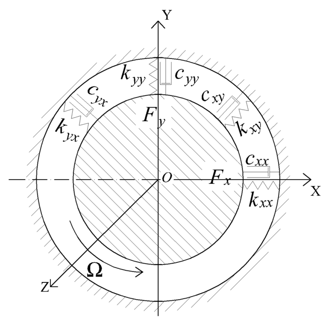
where F x 0 ,   F y 0 are the forces at the equilibrium position; F x i , F y i are disturbed forces in each direction; Δ x , Δ y are disturbed displacements and Δ x ˙ , Δ y ˙ are disturbed velocity. The linearized bearing water film forces using stiffness and damping coefficients are illustrated in Figure 2.

2.3. Bearing–Rotor Dynamic Model

The groove-textured WLHBs studied here are used to support the motorized spindle. Since a motorized spindle usually works under its first critical speed, the bearing–rotor system can be regarded as rigid. To eliminate the gyroscopic effects, two identical WLHBs symmetrically support a rotor, which is shown in Figure 3.

2.3.1. Stability Analysis

The bearing–rotor system will start oscillating from the equilibrium position when there is a small disturbance. The stiffness and damping coefficients of the bearings are then substituted into the transient dynamic equations of the bearing–rotor system:
{ m x ¨ + c xx x ˙ + c xy y ˙ + k xx x + k xy y = 0 m y ¨ + c yx x ˙ + c yy y ˙ + k yx x + k yy y = 0
When the rotor is disturbed by a small disturbance, the rotor will whirl around its steady position. When it is at the threshold of instability, the solution of Equation (7) is a pure imaginary number, which can be written as
x = A x e iw st t ,   y = A y e iw st t
where w is the whirling frequency of the rotor center.
Substitute solution (9) into Equation (8), the expression can be obtained as follows:
[ - mw st 2 + iw st c xx + k xx iw st c xy + k xy iw st c yx + k yx - mw st 2 + iw st c yy + k yy ] [ x y ] = [ 0 0 ]
The determinate of the matrix should be zero. Since both the real part and imaginary part should be equal to zero, there will be two equations. The critical whirling frequency and critical mass can be solved. By substituting the non-dimensional dynamic coefficients ( K = k ψ 3 μ Ω L , C = c ψ 3 μ L , where ψ = h 0 / L , h 0 is radial clearance and L is the length of the bearing), the non-dimensional critical mass Mst = m s t ψ 3 Ω μ L can be determined to assess the stability [26,27]. When the rotor mass is no greater than the critical mass, the rotor is stable; the greater the critical mass is, the more stable the rotor is.

2.3.2. Unbalance Response Analysis

Assuming that the residual unbalance is located in the plane of the mass center of the bearing–rotor system, the dynamic equations of motion can be expressed as follows:
[ M ] { X ¨ } + [ C ] { X ˙ } + [ K ] { X } = { Δ F }
where X represents the unbalance response of the rotor center in the orthogonal direction of x and y, [C] is the damping matrix and [K] is stiffness matrix.
The unbalance force Δ F is shown as follows:
{ Δ F } = { me m Ω 2 cos ( Ω t ) me m Ω 2 sin ( Ω t ) }
Equation (10) can be solved by using the fourth-order Runge–Kutta method to obtain the unbalance response of the rotor mass center ( x center ,   y cener ) .

2.4. Calculation Process

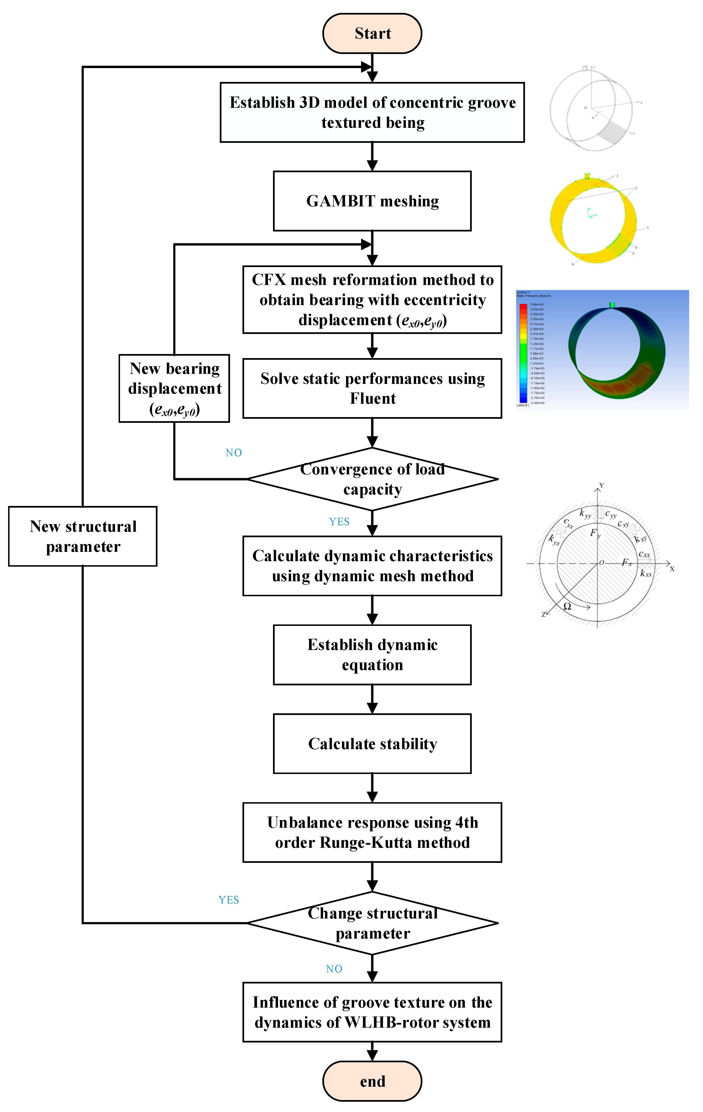
The static performances of groove-textured water-lubricated bearings can be investigated thoroughly using Fluent, as in our previous study [7]. Based on the static results, further calculation including the dynamic coefficients of the bearings, stability and unbalance response of the WLHB rotor using Fluent and Matlab are discussed in the following part. The computational procedure is depicted in Figure 4.
When the equilibrium position is obtained, the dynamic mesh method is adopted. The User Defined Function (UDF) in Fluent should be used to deal with the linear whirl motion of the rotor. In this process, since the position of the journal center changes due to the combined motions of translational and rotational motions, the traditional dynamic mesh method is no longer suitable due to the mesh distortion leading by rotational motion. To this point, two UDF macros are used [28,29]: the DEFINE_CG_MOTION macro is used to define the displacement and velocity whirling motion; the DEFINE_PROFILE macro is used to update the coordinates of the journal meshes that change according to the position of the journal.
To solve the stiffness and damping coefficients, the calculation is carried out in two steps: firstly, the disturbed velocities are assumed to be unchanged to calculate the stiffness, thus, the differences of velocities are zero ( Δ x ˙ = 0 ;   Δ y ˙ = 0 ); secondly, the disturbed displacements are assumed to be unchanged to calculate the damping coefficients, thus, the differences of displacements are zero ( Δ x = 0 ;   Δ y = 0 ).
In the first step, the dynamic equation can be expressed as follows:
{ F x i F x j = 2 ( k x x Δ x + k x y Δ y ) F y i F y j = 2 ( k y x Δ x + k y y Δ y )
where F x i is the force in the x direction with a disturbed displacement Δ x in the +x direction; F x j is the force in the x direction with a disturbed displacement Δ x in the −x direction. Similarly, F y i ,   F y j are the forces in the y direction with a disturbed displacement Δ y in the +y and −y directions, respectively. When the disturbed displacement in the x direction Δ x is applied and the disturbed displacement in the y direction Δ y is zero, the stiffness k x x can be solved. Similarly, when the disturbed displacement in the y direction Δ y is applied and disturbed displacement in the x direction Δ x is zero, the stiffness k y y can be solved. Then, both of the disturbed displacements in the x and y directions are applied by substituting the stiffness k x x and k y y into Equation (13); thus, the coupled stiffness k x y   and   k y x can be solved.
Similarly, in the second step, the dynamic equation can be expressed as follows:
{ F x i F x j = 2 ( c x x Δ x ˙ + c x y Δ y ˙ ) F y i F y j = 2 ( c y x Δ x ˙ + c y y Δ y ˙ )
The disturbed velocities in the x, y direction Δ x ˙ ,   Δ y ˙ are changed successively to solve the damping coefficients c x x and c y y . Then, both of the disturbed velocities in the x and y directions are applied by substituting the damping coefficients c x x and c y y into Equation (14); thus, the coupled damping coefficients c x y   and   c y x can be solved.
Then, by substituting the dynamic characteristics of the bearings into dynamic equations of rotor, the critical mass Mst to express the stability and the unbalance response using the fourth-order Runge–Kutta method will be solved by Matlab codes.
The water film is divided into meshes of 220 × 150 × 5 , and the sensitive analyses for meshes have been fully studied in our previous study [7].

3. Validation of the Calculation Process

A test rig was manufactured to verify the calculation of static performance of the WLHB in our previous study [7], which can partially validate the calculation of the CFD analysis since the static performance is the foundation of the dynamic characteristics. To verify the correctness and effectiveness of the dynamic mesh method to calculate the dynamic coefficients, two comparisons are carried out. Firstly, the stiffness coefficients of a smooth WHJB available from literature are calculated by the dynamic mesh method. Comparisons with the available results from the literature are used to partially show the correctness of calculation of the dynamic characteristics for a smooth bearing. Then, the stiffness coefficients of the grooved WHJB are calculated by both the UDF method and the difference of the load capacity method (DLC) according to the definition of stiffness to partially show the validation of the dynamic characteristics for a grooved bearing.
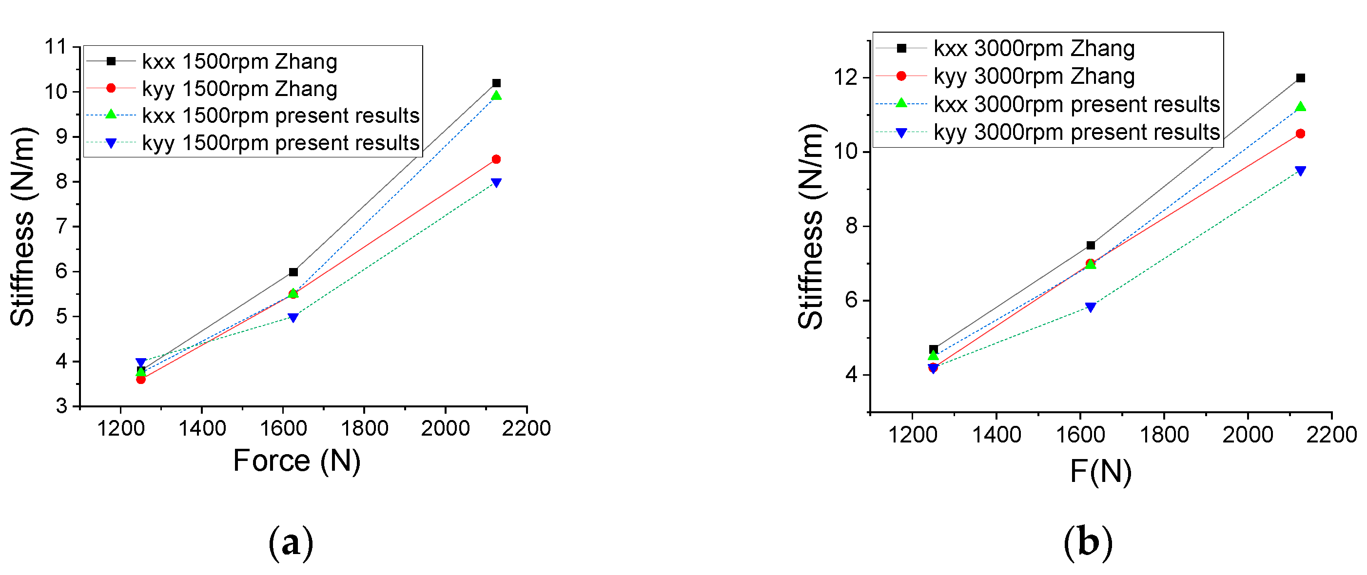
Since there are no available measurement data for validation of a smooth WHJB, the dynamic simulation procedure is verified with the simulation results from Ref. [30]. Comparisons of the stiffness coefficients k x x and k y y of a smooth WHJB calculated by the UDF method with the results obtained by Zhang, Yin et al. [30] are accomplished. As shown in Figure 5, according to the comparisons, the maximum error of the results by the present method and the results of Zhang, Yin et al. [30] are not greater than 16%.
Since the definition of stiffness is the ratio of the difference of load capacities to the difference of displacements, to further validate the correctness of UDF codes for grooved WHJB, results calculated by UDF using dynamic mesh method are compared with the ratio of the difference of load capacities to the difference of displacements using the static analysis method. Table 1 provides a list of the structural parameters of the WLHB. The eccentricity ratio is 0.3. There are ten grooves located in the region of 210°~240° and these are oriented axially through the bearing.
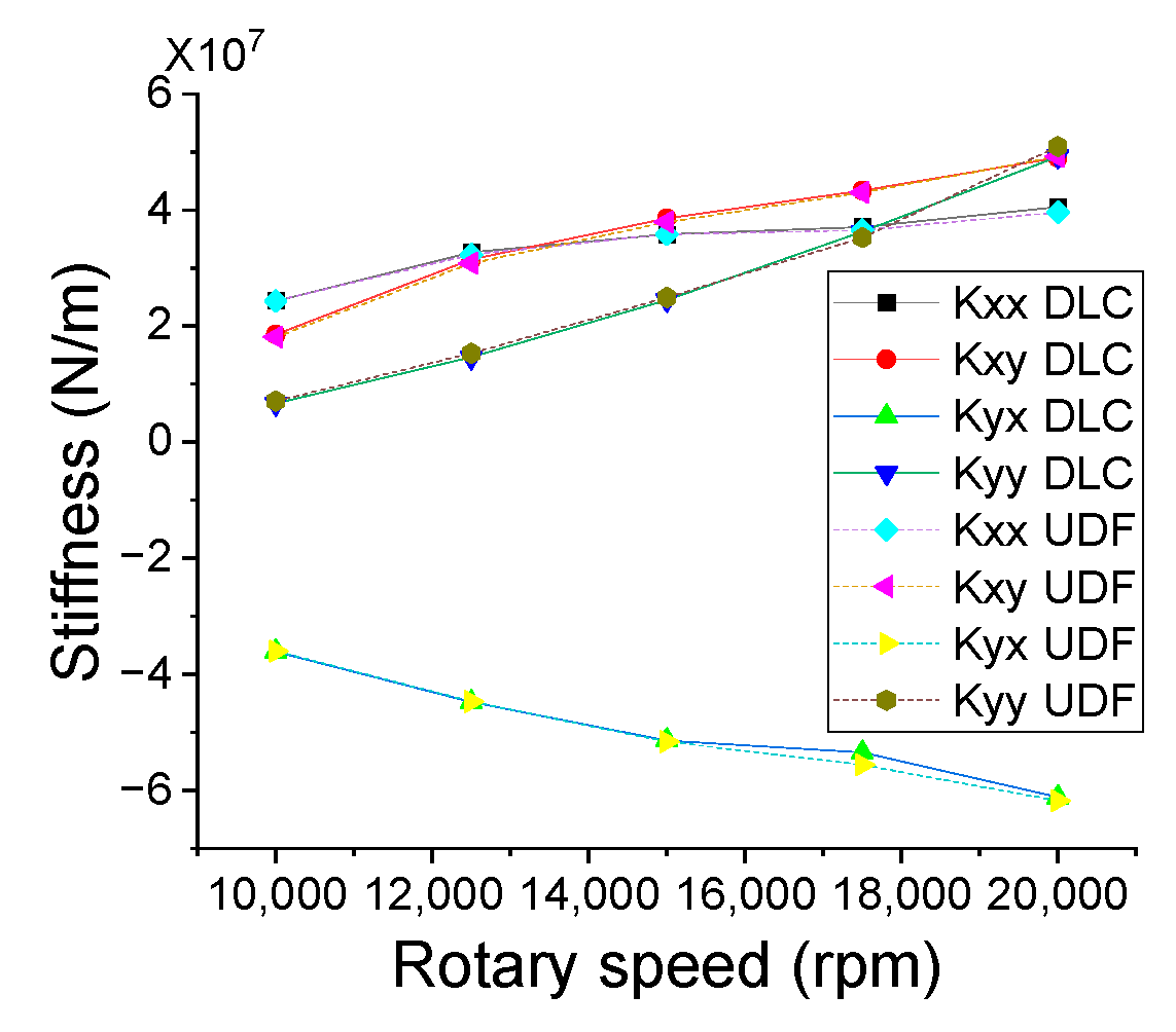
As illustrated in Figure 6, the stiffness coefficients obtained by the two methods match quite well, with a maximum difference of 6.6% at a rotary speed of 10,000 rpm for the direct stiffness k y y . Since the damping coefficients are defined as the response of load capacities to disturbed velocities, which cannot be solved by the difference of load capacity using the static method, the damping coefficient calculation cannot directly be verified. However, the calculation processes using the UDFs of stiffness and damping coefficients are quite similar, only replacing the disturbed displacement by a disturbed velocity. So, the applicability and reliability of the UDF codes is verified to obtain the dynamic coefficients for the groove-textured water-lubricated bearings.

4. Results and Discussion

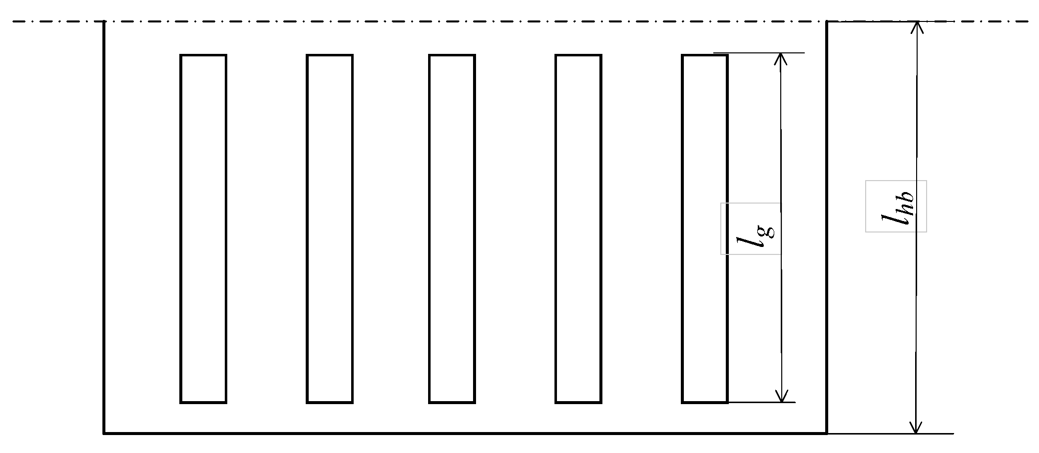
The combined influences of working condition and structural parameters of groove texture on the dynamic coefficients, stability and unbalance response of a rotor supported by both the smooth and grooved WLHBs are thoroughly studied. As shown in Figure 7, the groove length ratio λl is calculated by dividing the axial length of the groove (lg) by half of the axial length of the bearing (lhb). When λl is 1, the grooves are axial through the bearing. Initial parameters of the grooved WLJB are listed in Table 1. In the following discussion, when the increase or decrease in the dynamic coefficients is beneficial to the dynamics of the bearing–rotor system, the groove texture is considered to be able to improve the dynamic coefficients.

4.1. Dynamic Characteristics of Groove-Textured WLHB

The combined influences of working condition and structural parameters of groove texture on the dynamic coefficients, stability and unbalance response of a rotor supported by both the smooth and grooved WLHBs were thoroughly studied.

4.1.1. Effects of Rotary Speed

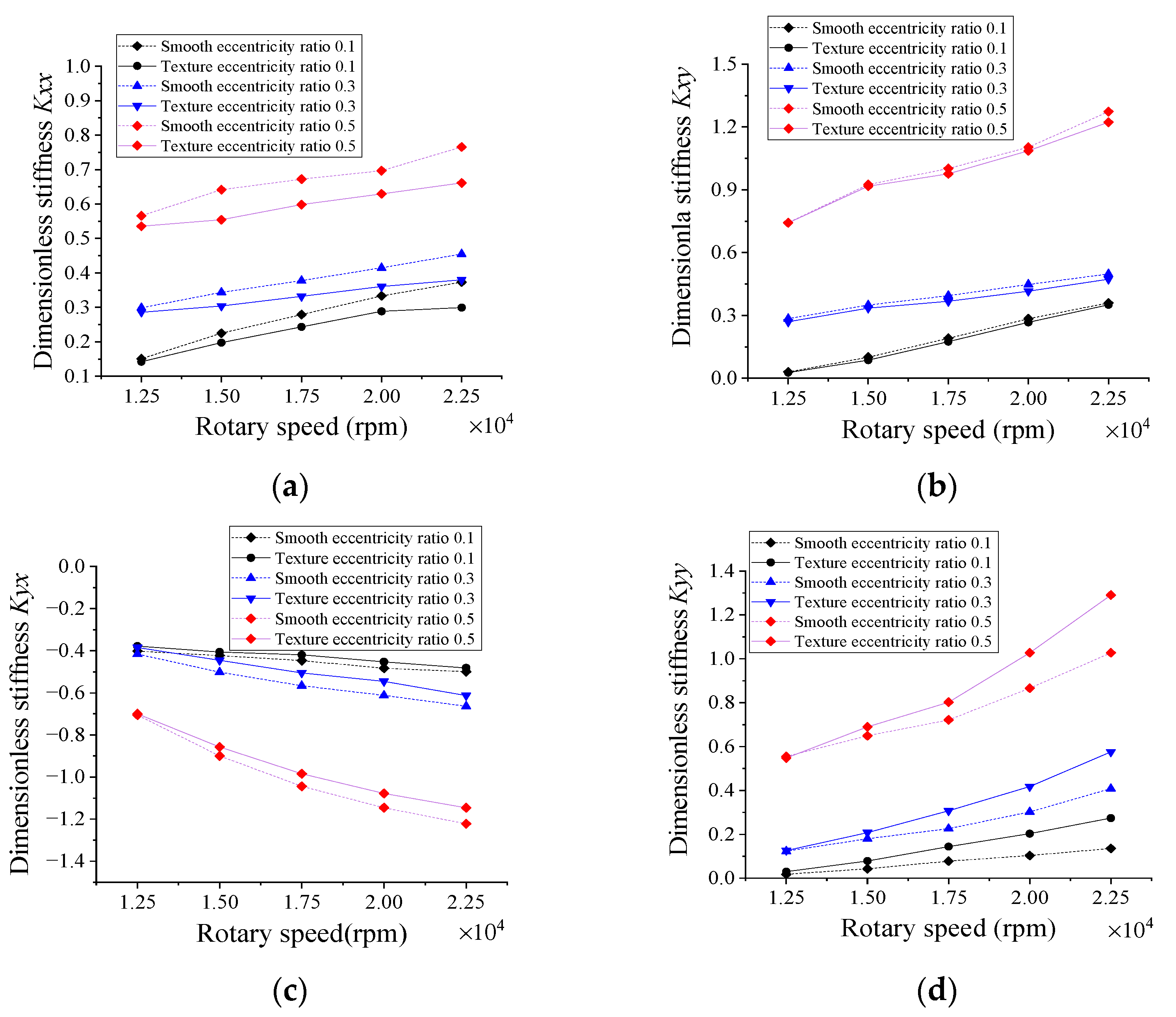
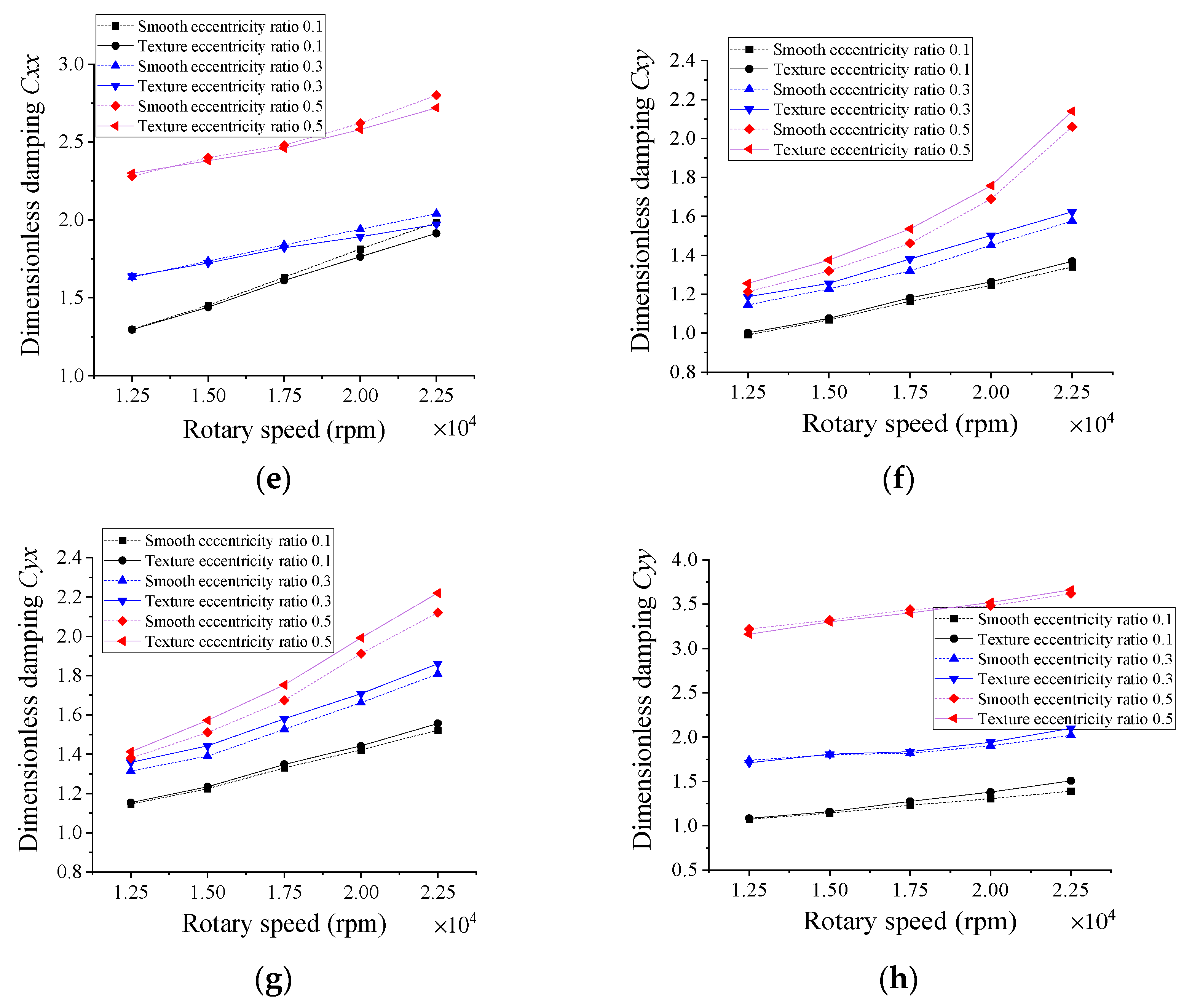
Figure 8a–h show the effects of rotary speed on stiffness and damping coefficients of both the smooth and groove-textured, water-lubricated, hydrodynamic bearings. The width and depth of a groove are 0.1° and 10 μm, respectively.
As shown in the figure, compared with the smooth bearing, the direct stiffness coefficients k x x are smaller for the groove-textured bearing, and the differences become increasingly prominent with higher rotary speeds. However, the direct stiffness coefficients k y y along the main load direction of the groove-textured bearing are greater than those of the smooth bearing; the higher the rotational speed becomes, the greater the differences become. The groove texture can improve the stiffness along the load direction and weaken the stiffness in the orthogonal direction, especially at greater rotary speed. The reason for this is probably that larger rotary speed could promote an extra hydrodynamic effect along the load direction; thus, the stiffnesses k y y of the groove-textured bearing are larger than those of the smooth bearing. Furthermore, the greater the rotary speed is, the more significant the hydrodynamic effect it generates. However, in the orthogonal direction, the reduction exceeds the improvement introduced by the groove texture.
For the coupled stiffness k x y and k y x illustrated in Figure 8b,c, the groove texture decreases the absolute values compared with those of the smooth bearing. The reason for this is that the presence of the groove texture can produce several small convergence regions, leading to changes of the cavitation area and distribution of pressure. The reduction in cavitation area can improve the hydrodynamic effect along the load direction and weaken the hydrodynamic effect along the orthogonal direction; furthermore, instead of one convergence region, several small convergence regions may break the generation of whirling motion.
Figure 8e–h illustrate the influences of the groove texture on damping coefficients of both the smooth and grooved bearings. The study demonstrates that the damping coefficients increase with respect to rotary speed. The variation amplitudes of direct damping coefficients c x x and c y y are smaller than those of coupled ones and the c y y of the groove-textured bearing gradually exceeds that of the smooth one. However, the effect of the groove texture on c y y with rotary speed is quite opposite to that in the orthogonal direction c x x . As illustrated in Figure 8f,g, the groove texture increases the coupled damping coefficients c x y and c y x . It should be noted that no matter the improvement or weakness, with the increased rotational speed, the groove texture has little effect on the damping coefficients compared to stiffness.

4.1.2. Effects of Eccentricity Ratio

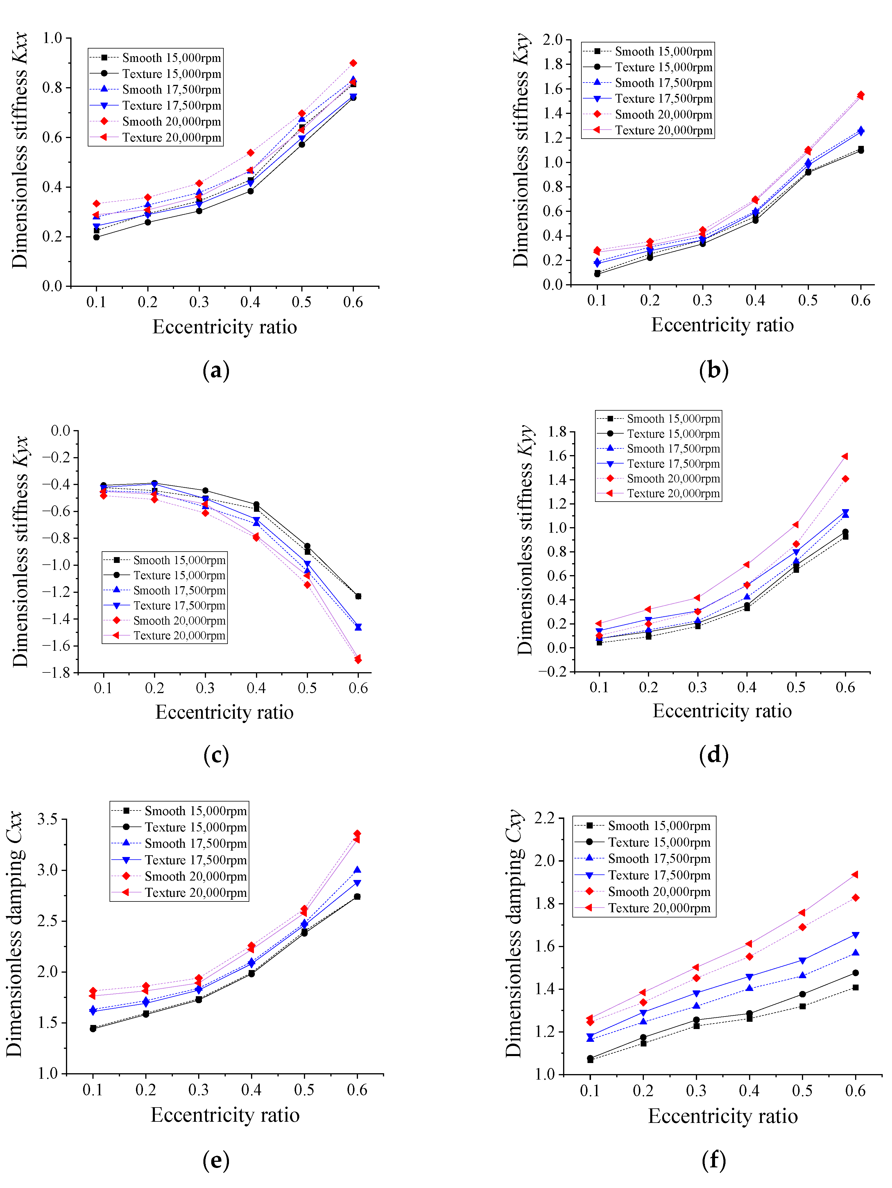
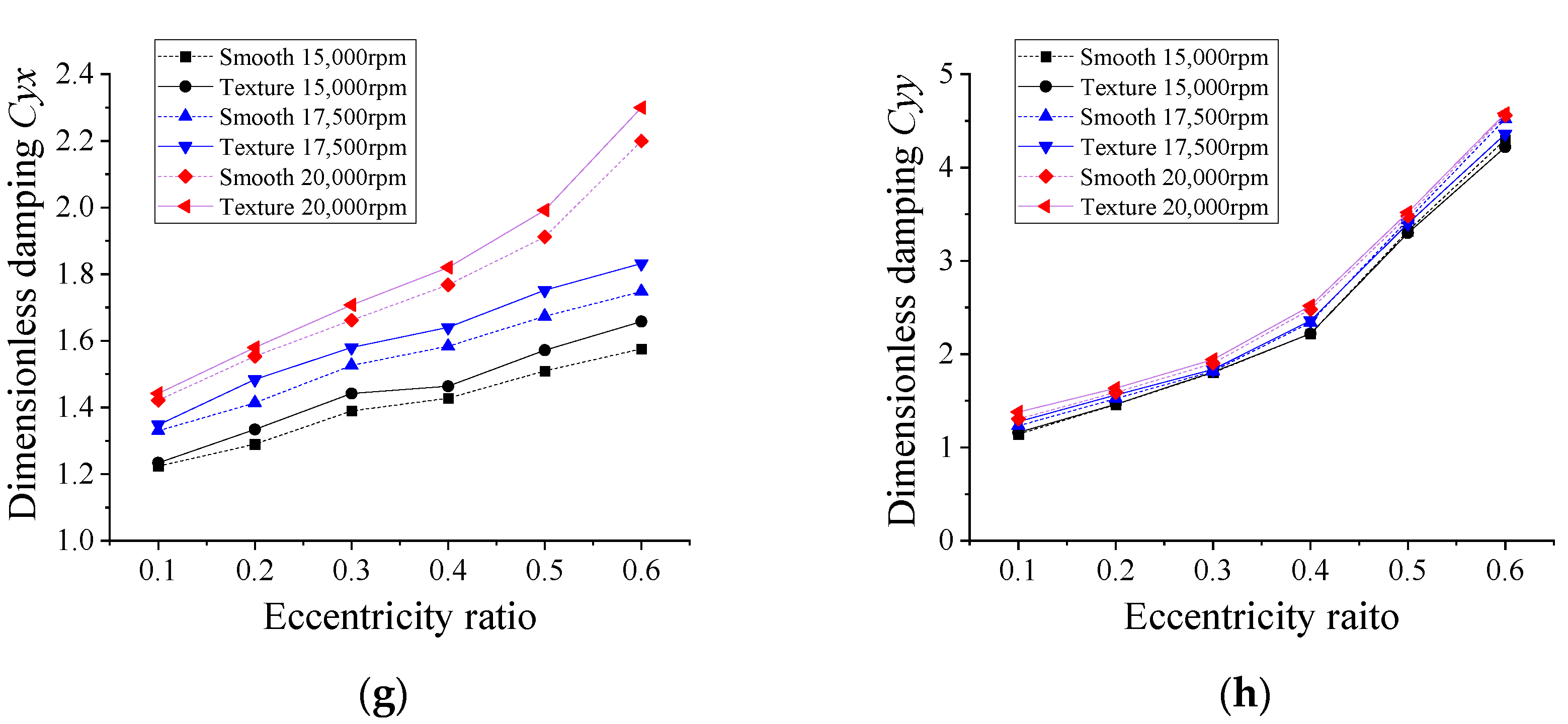
The influences of eccentricity ratio on the stiffness coefficients are shown in Figure 9a–d. The width, depth and groove length ratio λl of a groove are 0.1°, 10 μm and 1, respectively. As shown in Figure 9, by comparing the stiffness coefficients of groove-textured WLHB and smooth WLHB, it is found that the stiffness along the direction of load k y y is significantly improved by the groove texture, especially at higher rotary speed and smaller eccentricity ratio. Operating at 20,000 rpm with an eccentricity ratio of 0.1, the value of stiffness k y y of groove-textured WLHB is almost double that of smooth WLHB. Besides, the magnitudes of coupled stiffness coefficients k x y ,   k x y are decreased by the groove texture. The reason for this is probably that along the axis of the applied force, the existence of the groove texture generates additional hydrodynamic pressure and weakens the coupling motion of water.
Figure 9e–h show the influence of coupled eccentricity ratio and groove texture on the damping coefficients. According to the results, at a larger eccentricity ratio and greater rotary speed, the direct damping coefficient in the direction of the applied load c y y is greater than that in the perpendicular direction c x x . It is noted that with an increased eccentricity ratio, the direct damping coefficients c x x and c y y are little affected by the groove texture while the coupled damping coefficients are improved by the groove texture by no more than 10%.

4.1.3. Effects of Groove Depth

Figure 10a–h present the dynamic coefficients of WLHBs versus groove depth at 15,000 rpm, 17,500 rpm and 20,000 rpm and an eccentricity ratio of 0.1. The groove width is 0.1° and the groove length ratio λl is 1.
As shown in Figure 10a,b, with an increase in groove depth from 10 μm to 30 μm, the stiffness k y y is significantly improved; however, when the groove depth becomes deeper, the improvement by the groove texture on k y y remains almost unchanged. For example, for the value at a rotary speed of 20,000 rpm and eccentricity ratio of 0.1, k y y with a groove depth of 10 μm is approximately double that of k y y of the smooth bearing. Besides, the absolute values of coupled stiffness k y x and k y x of the groove-textured WLHB are smaller than those of the smooth bearing. The results indicate that a shallower groove texture can improve the direct stiffness in the direction of the applied load k y y more significantly than a deeper one. The reason for this is probably that with the groove depth increase from 10 μm to 30 μm, the flow vortex generated at the bottom of groove is enhanced significantly, leading to a sharp variation in the stiffness; however, with further increased groove depth, the effect of flow vortex at the bottom of the groove weakens gradually, leading to a nearly unchanged variation in stiffness.
As shown in Figure 10e–h, compared with smooth WLHB, for most of the cases, the groove texture can improve the damping coefficients by no more than 10% with increased groove depth. When the groove depth increases from 10 μm to 20 μm, the damping coefficients of groove-textured WLHB change slightly; however, with increased groove depth, the damping coefficients remain almost unchanged. The reason for this is that damping is a function of the pressure variation for a given squeeze velocity, which is not dependent on the groove depth.

4.1.4. Effects of Groove Width

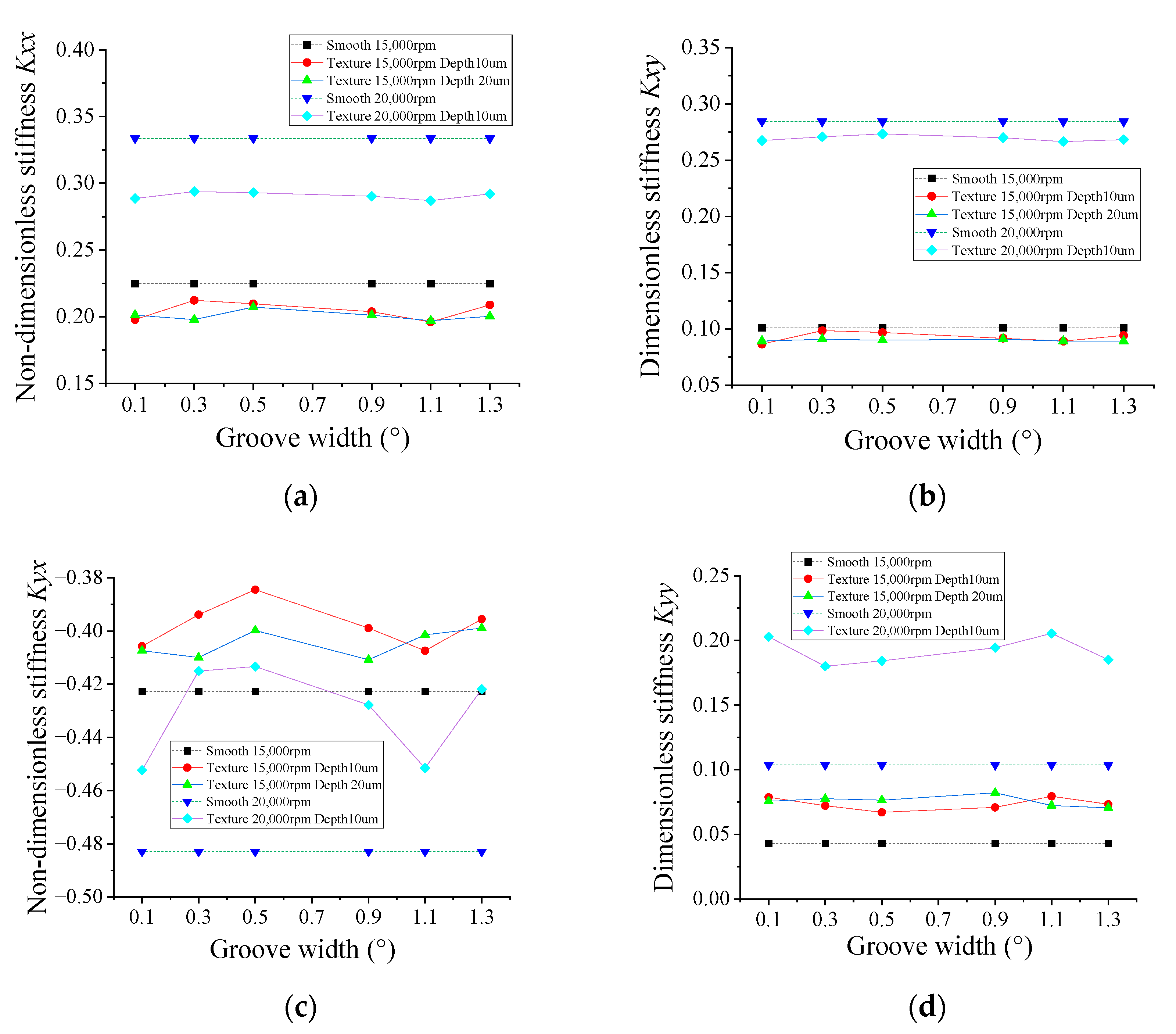
The effects of groove width on stiffness are illustrated in Figure 11a–d. The eccentricity ratio and groove length ratio λl are 0.1 and 1, respectively. As shown in Figure 11, with the increased groove width, the stiffness either shows an increase–decrease–increase trend or decrease–increase–decrease trend. These tendencies are likely to be caused by a combination of turbulence and flow vortex. As the width of the groove is increased, the cavitation area will change and the flow vortex generated at the bottom of the texture is reduced. Shrinking of the cavitation surface and reduced flow vortex can improve both the load capacity and the stiffness k y y . Therefore, the overall load capacity and stiffness in the direction of load application can only be improved by the texture if the positive impact is greater than the negative impact caused by the confluence of flow vortex and cavitation.
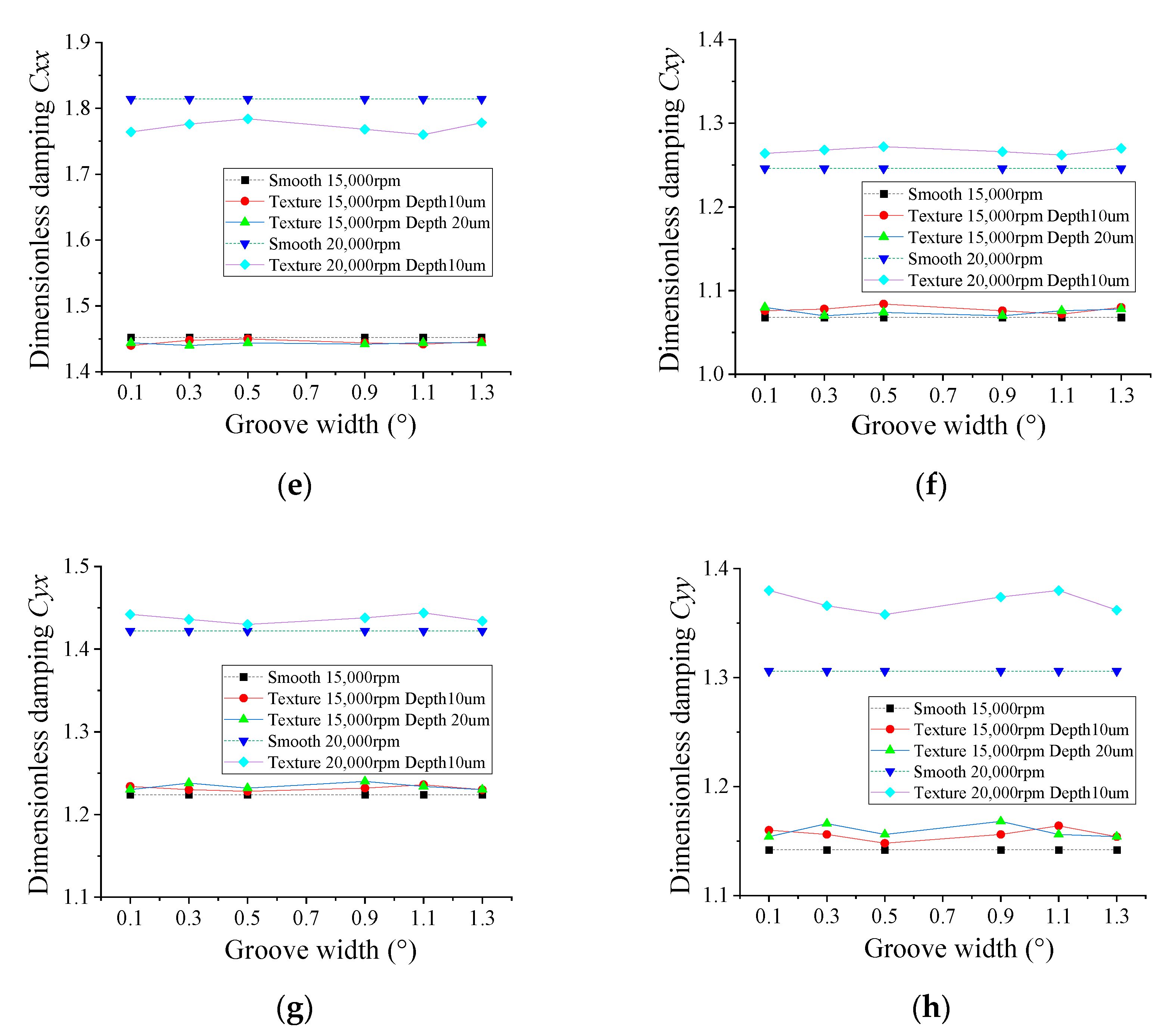
As for the damping coefficients presented in Figure 11e–h, c y y , c x y and c y x of the surface-textured WLHB are generally greater than those of the smooth WLHB. This is an indication that the groove texture weakens the whirling motion of the bearing. It is noted that the increase–decrease–increase trend or the opposite trend is also found. Two peaks for c y y are obtained at the groove widths of 0.1 and 1.1 degrees for bearings with a groove depth of 10 μm as well as at the groove width of 0.3 and 0.9 degrees for bearings with a groove depth of 20 μm. It should be noted that for bearings with a greater rotary speed, the effect of groove width on damping coefficients is more significant than at a lower rotary speed.

4.1.5. Effect of Groove Length Ratio

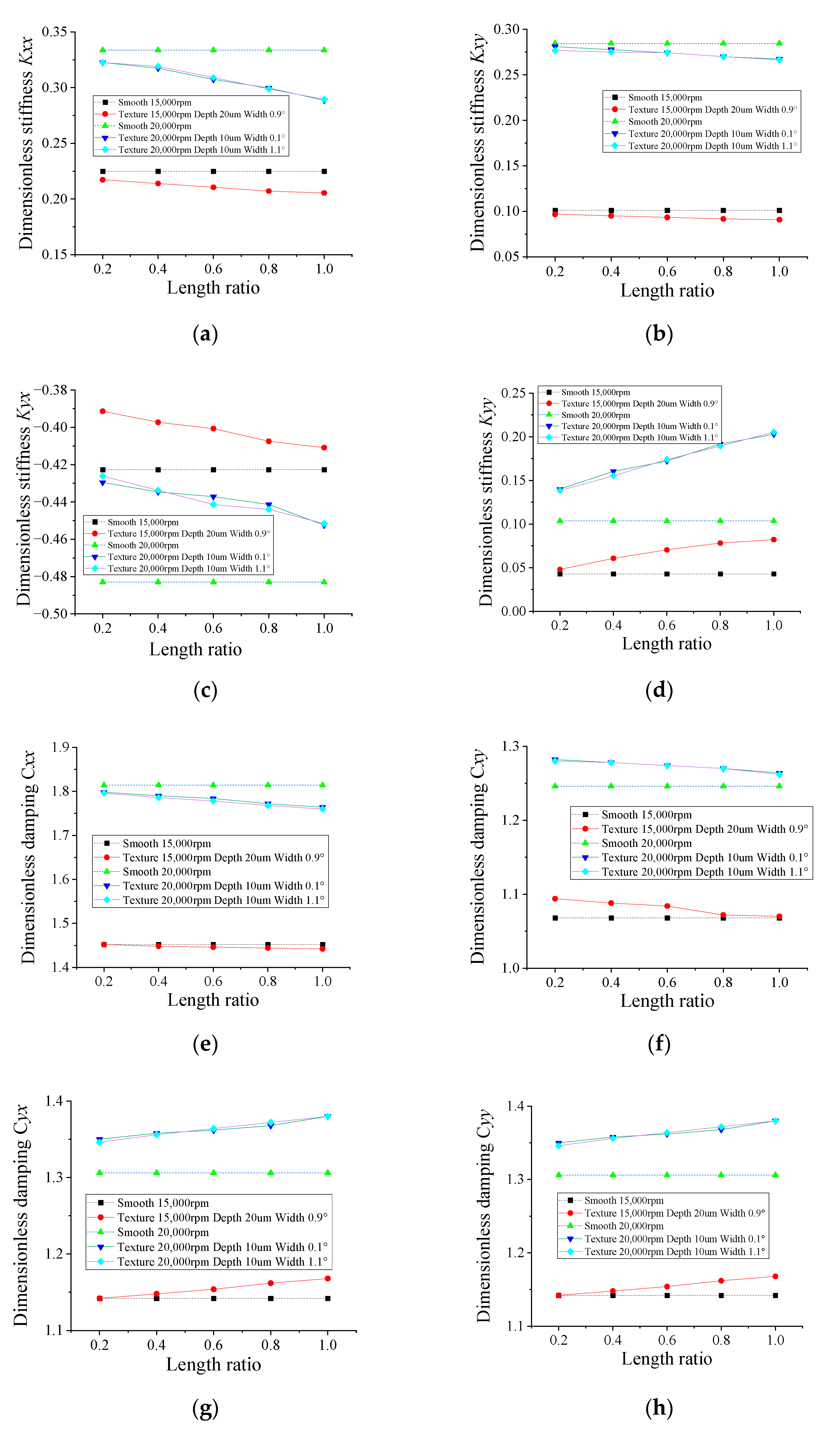
Figure 12a–h show the effect of groove length ratio on the dynamic coefficients. Two symmetrical grooves are distributed along the axis when the ratio of the groove length is less than 1. According to the results, compared with the stiffness coefficients of the smooth bearing, the k y y of the groove-textured WLHB is greater, while the absolute values of k x y   and   k y x of the groove-textured WLHB are smaller. For the three cases with a groove length ratio of 1, the improvement of the direct stiffness coefficient in the load application direction is 91.7%, 96.0% and 98.4%, respectively, indicating the significant improvement of grooves on the dynamic coefficients. The additional hydrodynamic effect produced by the groove texture is probably responsible for this. The longer the groove texture is, the more significant the extra hydrodynamic effect that is generated.
As for the damping coefficients illustrated in Figure 12e–h, c y x and c y y increase while the orthogonal damping coefficients decrease with increasing groove length ratio. Except for c x x , all the other damping coefficients of the textured bearing are greater than those of the smooth bearing, indicating that the groove texture can suppress the whirling motion.

4.2. Stability of Groove-Textured, Water-Lubricated Bearing–Rotor System

4.2.1. Effects of Rotary Speed

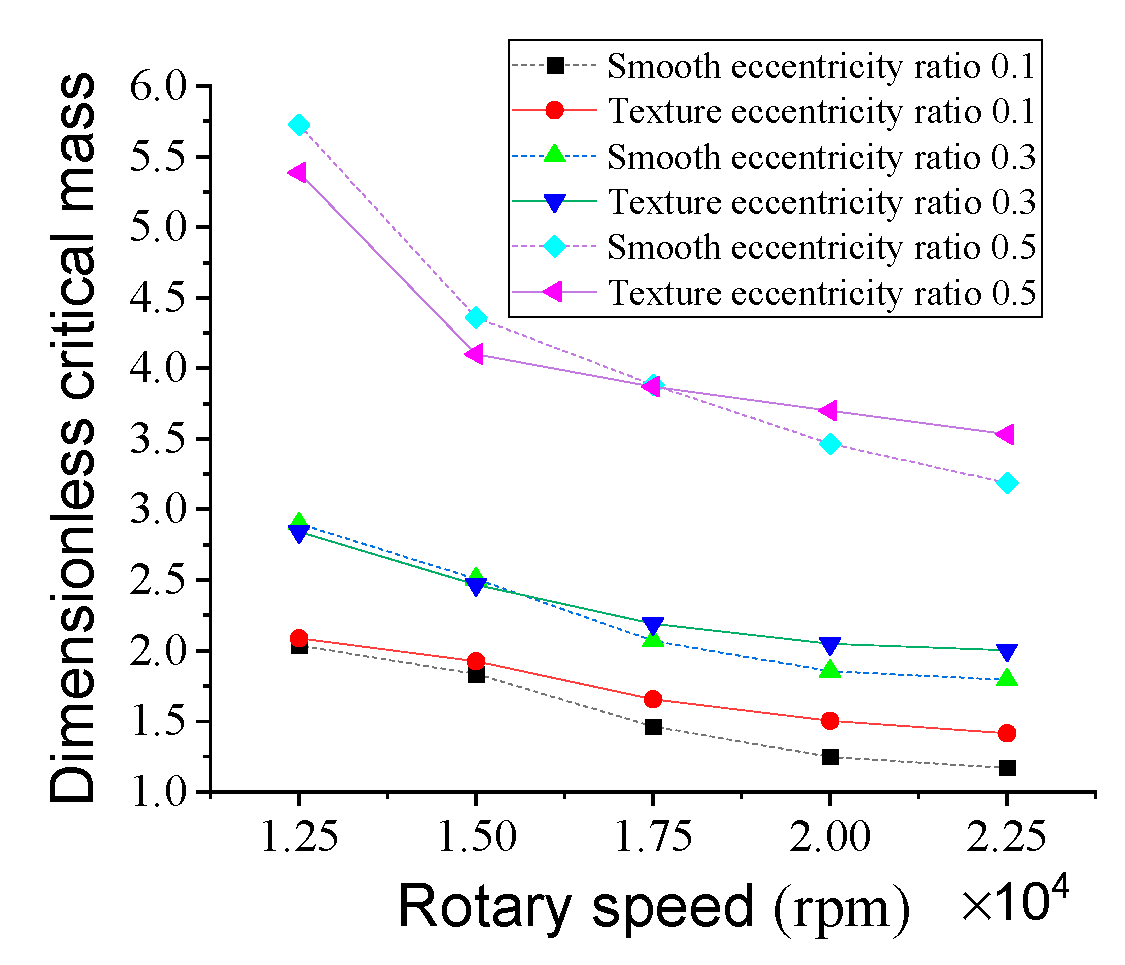
Figure 13 presents the dimensionless critical mass of a rotor supported by two identical WLHBs as a function of rotary speed. As can be seen in Figure 13, as the rotational speed increases, the critical masses of both the grooved and smooth WLHBs decrease, indicating that the stability of the rotor gradually deteriorates. When the eccentricity ratio is 0.1, compared with the smooth bearing, the stability of the groove-textured WLHB is improved when the rotary speed varies from 12,500 rpm to 22,500 rpm. The stability of the rotor supported by the groove-textured bearings improves significantly, from approximately 2.4% to 20.9% with an eccentricity ratio of 0.1, when the rotary speed increases to 22,500 rpm. The groove texture has a more significant stabilizing effect at higher rotary speeds. However, when the rotary speed is 12,500 rpm, the critical mass of the grooved bearing is approximately 2.0% and 5.9% smaller than that of the smooth one at eccentricity ratios of 0.3 and 0.5, respectively, indicating that the groove texture plays a negative role under these conditions. With the increased rotary speed, the difference in critical mass between the grooved and smooth bearings grows steadily, illustrating that grooves can play a more obvious positive effect on the stability of the grooved WLHB rotor system at greater rotary speeds. However, for a low rotary speed and large eccentricity ratio, the WLHB might be weakened by the groove texture.
The cause of this can be attributed to the improvement of direct stiffness and direct damping coefficient in the direction of the applied load, as well as the weakening of whirling motion due to the existence of the groove texture with proper parameter settings. The decrease in coupled stiffness and increase in coupled damping coefficients of groove-textured WLHB are also important factors influencing the stability of the rotor.

4.2.2. Effects of Eccentricity Ratio

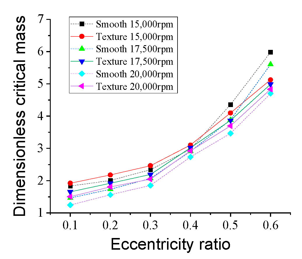
Figure 14 presents the influences of eccentricity ratio on the stability of the WLHB rotor system. It can be deduced that the stability becomes more pronounced as the eccentricity ratio increases. Compared with the smooth bearing, the stability is improved by 2.7~20.5% when the bearing is rotating at 20,000 rpm with an eccentricity ratio from 0.1 to 0.6; however, when the rotary speed decreases to 15,000 rpm, only when the eccentricity ratio is not greater than 0.4 can the stability be improved by the groove texture. The reason for this is probably that the promotion of whirling motion induced by the increase in coupled stiffness coefficients exceeds the suppression of whirling motion by the damping coefficients at a low rotary speed and large eccentricity ratio. Furthermore, at a high rotary speed, the extra hydrodynamic effect generated by the groove texture can also improve the stability of the rotor.

4.2.3. Effects of Groove Depth

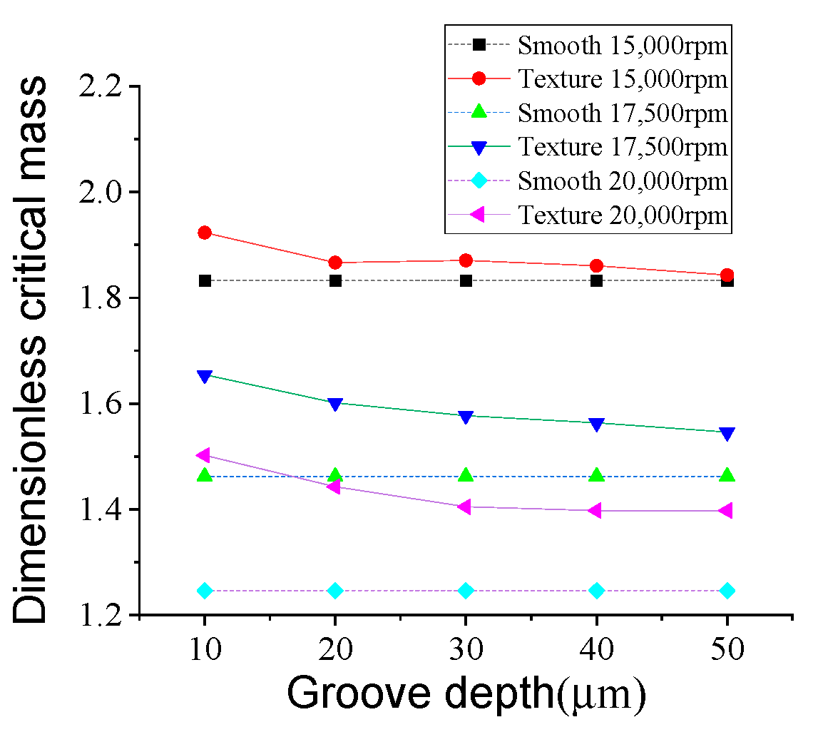
Figure 15 shows the stability with respect to groove depth. The groove width is 0.1° and the groove length ratio is 1. As shown in Figure 15, the critical masses of the groove-textured bearing are greater than those of the smooth bearing when the groove depth increases from 10 μm to 50 μm. As the depth of the groove grows, the critical mass decreases. Specifically, when the groove depth is 50 μm and rotary speed is 15,000 rpm, the critical mass of the grooved bearing is only 0.53% greater than that of the smooth one, while the critical mass of the grooved bearing is 20.53% larger when the groove depth is 10 μm and the rotary speed is 20,000 rpm. The results indicate that the stability of the water-lubricated bearing–rotor can be improved at a high rotary speed with a shallow groove.

4.2.4. Effect of Groove Width

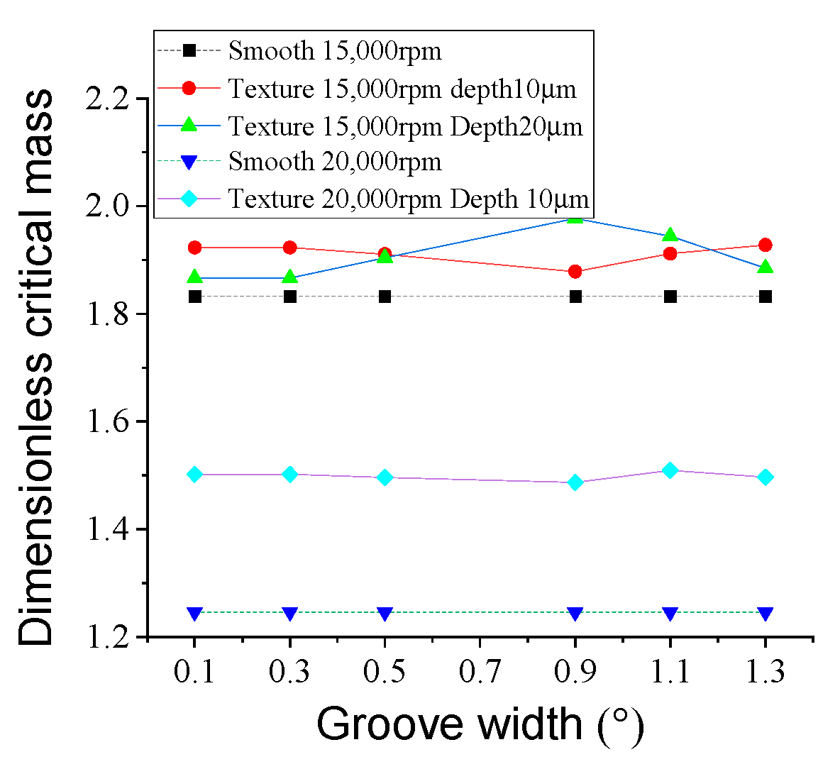
The effect of groove width on rotor stability is shown in Figure 16. The groove length ratio λ l is 1. According to Figure 16, the critical masses in all cases are greater than those of the smooth bearing. When the rotary speed is 20,000 rpm and groove depth is 10 μm, the stability is improved by a maximum of 21%, approximately. When the groove depth is 10 μm, the critical mass reaches its peak value at groove widths of 1.3 degrees and 1.1 degrees for both 15,000 rpm and 20,000 rpm; however, when groove depth increases to 20 μm, the best groove width to improve the stability is 1.1 degrees. Generally, there exists an optimum groove width to improve stability.

4.2.5. Effect of Groove Length

The effect of groove length on the stability of the water-lubricated bearing–rotor is shown in Figure 17. With the increased length ratio, the stability of the grooved bearing–rotor system increases gradually. For the rotor at a rotary speed of 15,000 rpm, the groove texture can weaken the stability when the length ratio is less than 0.5. However, for the rotor at a rotary speed of 20,000 rpm, the groove texture improves the stability significantly. Further, the greater the ratio of the length is, the more significant the contribution of the groove texture to stability is. When the length ratio is 1, the stability is improved by about 20.5% with groove widths of 0.1 degrees and 1.1 degrees at a rotary speed of 20,000 rpm. However, when the length ratio decreases to 0.2 for a bearing with a groove width of 0.9 degrees and depth of 20 μm at 15,000 rpm, the critical mass of the groove-textured bearing is only about 0.78% larger than that of the smooth bearing. Results show that the improvement by groove texture is more significant at a larger groove length ratio and greater rotary speed.

4.3. Unbalance Response of Groove-Textured, Water-Lubricated Bearing–Rotor System

To evaluate the effects of groove texture on the unbalance response of the rotor, the amplitude of unbalance response is studied. The residual unbalance is 1 × 10 6 ( kg Δ m ) . The time interval is 1 × 10 6 s and 10,000 time steps are run to ensure a steady state.

4.3.1. Effect of Rotary Speed

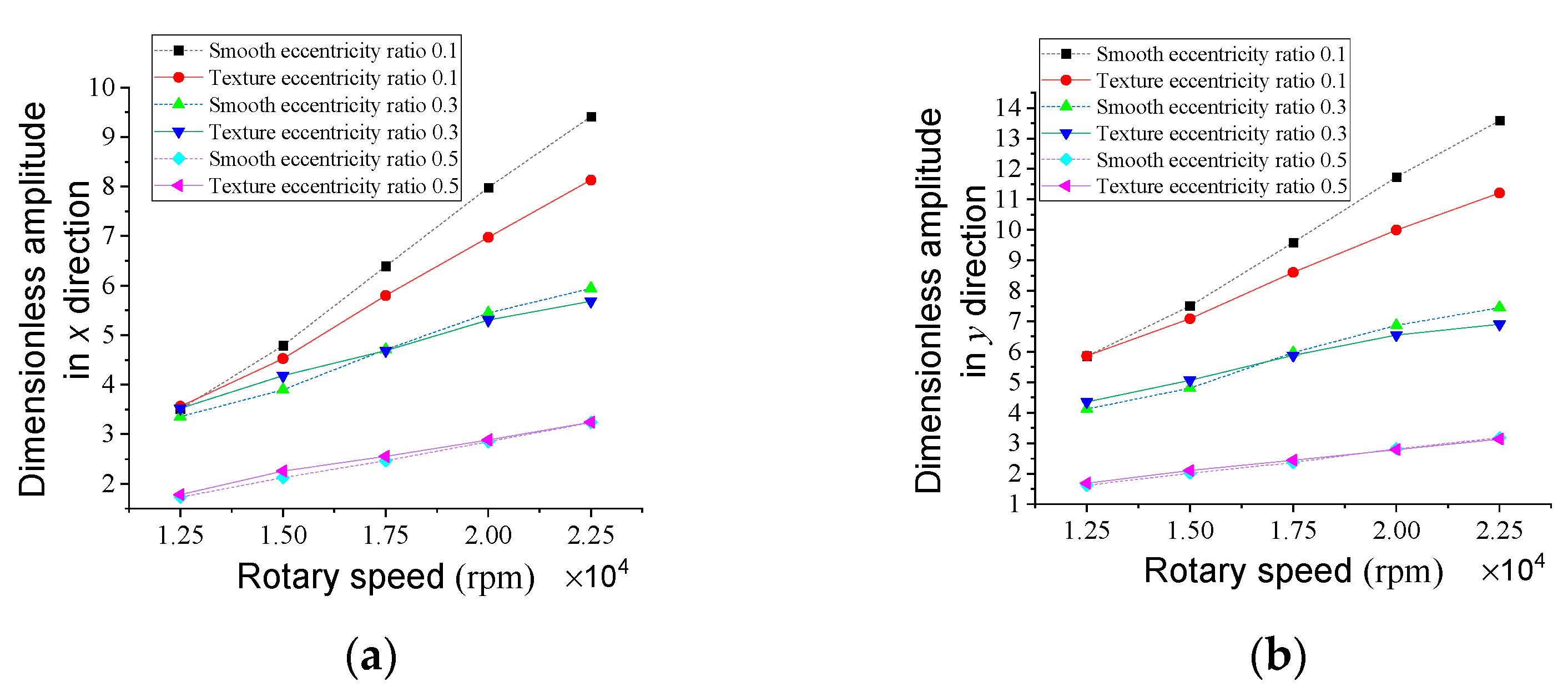
The combined effects of rotary speed and groove texture on the unbalance response of the water-lubricated bearing–rotor system is illustrated in Figure 18. The groove width is 0.1 degrees, the depth is 10 μm and the ratio of length is 1. As shown in the figure, both the unbalance responses of the groove-textured and smooth water-lubricated bearing–rotor system increase with the rotary speed. It should be noted that at speeds above 17,500 rpm and eccentricity ratio of 0.1, grooves can decrease the amplitude in both the x and y directions. When the rotary speed is 20,000 rpm and eccentricity ratio is 0.1, the amplitudes of unbalance in the x and y directions are reduced by approximately 10.51 and 3.79%; when the rotary speed increases to 22,500 rpm, the amplitudes of unbalance in the x and y directions are reduced by approximately 13.55 and 4.65%. However, at a lower rotary speed or larger eccentricity ratio, the groove will increase the amplitude of the unbalance response.

4.3.2. Effect of Eccentricity Ratio

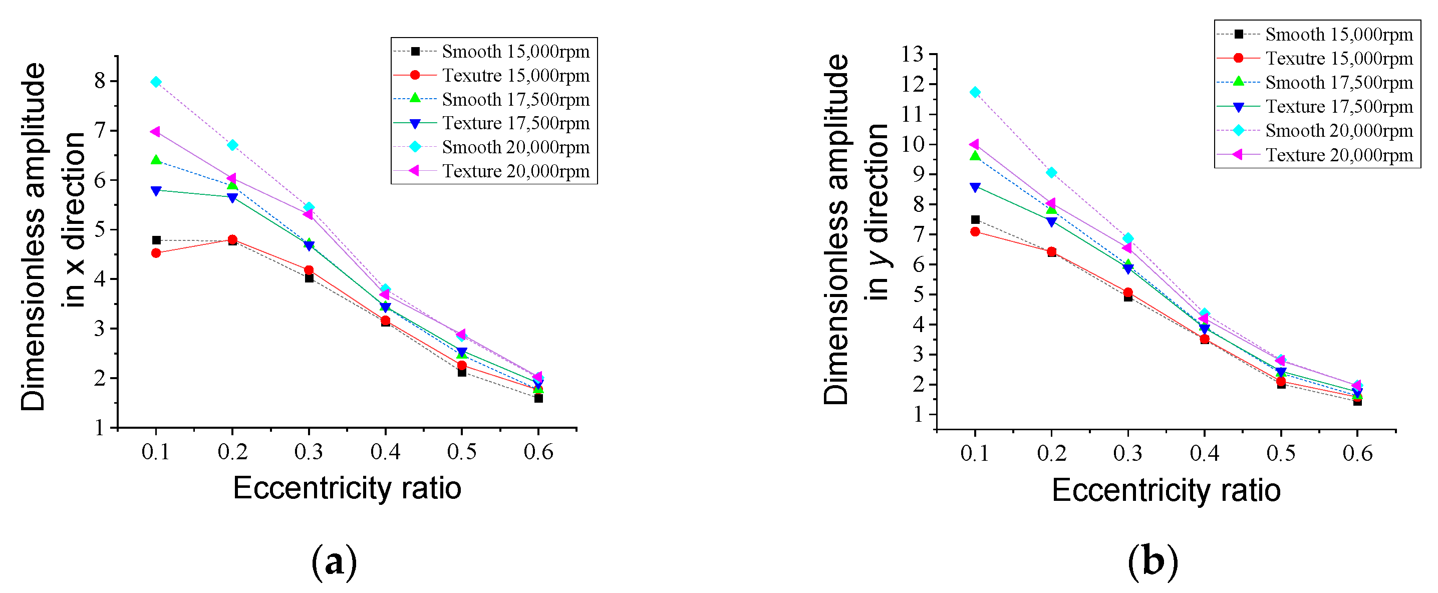
The unbalance responses of the smooth bearing–rotor and grooved bearing–rotor in terms of eccentricity ratio are presented in Figure 19. As shown in Figure 19a, the amplitudes of unbalance in both the x and y directions decrease with increased eccentricity ratio due to the increased direct stiffness coefficients and damping coefficients. It should be noted that only with an eccentricity ratio of 0.1 and a rotational speed of 20,000 rpm, the groove texture can decrease the unbalance amplitude by 10.51% and 3.79%, respectively. When the eccentricity ratio is 0.1, the groove texture can reduce the amplitude at rotational speeds of 15,000 rpm, 17,500 rpm and 20,000 rpm; when it increases to 0.3, the groove texture will be beneficial to the dynamics of the rotor with a rotational speed of 17,500 rpm or 20,000 rpm. However, when the eccentricity ratio increases to 0.5, the amplitude can only be reduced by the groove texture at a high rotational speed of 20,000 rpm.
In general, at a small eccentricity ratio and great rotational speed, the groove texture is beneficial to the dynamics of rotor; however, at a small eccentricity ratio and lower rotary speed, the groove texture significantly increases the unbalance response; with the further increased eccentricity ratio, the rotor dynamics are not significantly affected by the groove texture.

4.3.3. Effect of Groove Depth

The effects of groove depth on unbalance response are shown in Figure 20. The groove texture can decrease the unbalance response in both the x and y directions with respect to groove depth when the rotary speed is 20,000 rpm. The most significant decrease in groove texture on unbalance response exists at a rotary speed of 20,000 rpm and groove depth of 10 μm, which is 10.51% and 3.79% in the directions of x and y, respectively. It can be seen that the reduction in unbalance response is greater at shallower depth. However, at speeds below 20,000 rpm, the groove texture gradually increases the amplitude with groove depth.

4.3.4. Effect of Groove Width

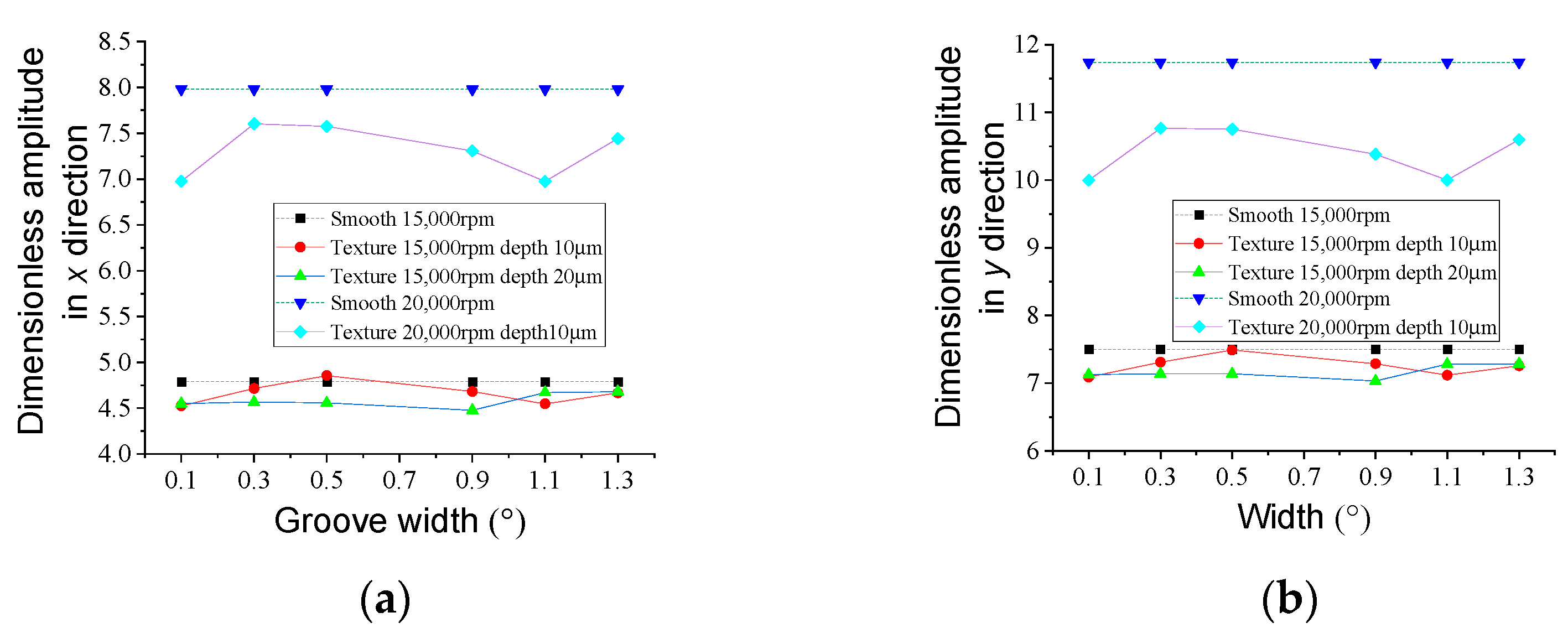
Figure 21 shows the influence of groove width on unbalance response. According to the results, the amplitudes in both the x and y directions increase first, then decrease and then increase with the increased eccentricity ratio. Two valleys exist when the groove width increases from 0.1 degrees to 1.3 degrees. The minimum unbalance amplitudes of the grooved WLHB rotor for the three cases are 5.1%, 6.5% and 12.6% smaller than those of the smooth WLHB rotor in the x direction and 5.5%, 6.3% and 14.8% smaller than those of the smooth WLHB rotor in the y direction.

4.3.5. Effect of Groove Length Ratio

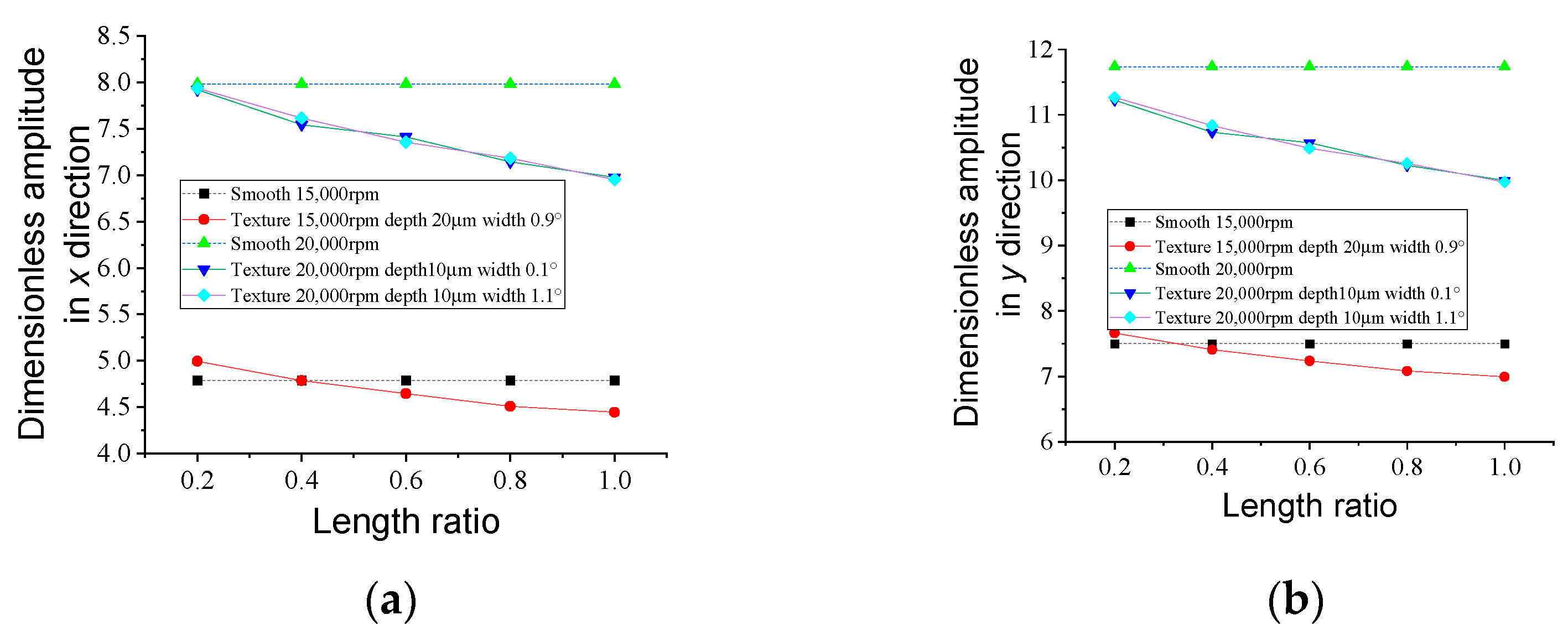
The effect of groove length ratio on the unbalance response is shown in Figure 22. According to the results, generally, the unbalance response in both directions of x and y decrease with respect to groove length ratio. The most significant improvement exists when the groove length ratio is 1.0, groove depth is 10 μm and rotary speed is 20,000 rpm. The effect of the groove texture on unbalance response changes from negative to positive, indicating that a larger groove length ratio can be beneficial for the dynamics of the water-lubricated bearing–rotor system.

5. Conclusions

(1)
The groove texture can enhance the direct stiffness along the load direction k y y and weaken the stiffness in the orthogonal direction k x x , especially at greater rotational speed, smaller eccentricity ratio, and a shallower and longer groove. When a bearing with a groove depth of 10 μm, a groove length of 1 and width of 1.1 degrees is working at 20,000 rpm and a 0.1 eccentricity ratio, the stiffness k y y can be improved by 98.4%. With the increased width of the groove, the dynamic coefficients show an increase–decrease–increase trend or decrease–increase–decrease trend; with increased eccentricity ratio and rotary speed, the groove texture has little effect on the direct damping coefficients but improves the coupled damping coefficients; for most of the cases, the damping coefficients can be improved with increased groove depth; with the increased width of the groove, the damping coefficients increase slightly. These complex variations may be attributed to the combination of cavitation and flow vortex.
(2)
The groove texture can play a more obvious positive effect on the stability of a rotor supported by WLHBs with shallow and longer grooves at a greater rotary speed and smaller eccentricity ratio; there exists an optimum groove width to achieve the largest critical mass. When the length ratio is 1, the stability is improved by about 20.5% with groove widths of 0.1 degrees and 1.1 degrees at a rotary speed of 20,000 rpm. The main reason for this phenomenon is due to the improvement of direct stiffness and direct damping coefficient in the direction of the applied load, as well as the weakening of whirling motion due to the existence of a groove texture with proper parameter settings.
(3)
As for the unbalance response, the groove texture is beneficial for the dynamics of the rotor at a small eccentricity ratio and great rotary speed. A shallower and longer groove can decrease the unbalance response more apparently; there exists an optimal groove width to decrease the amplitude of the unbalance response. The most significant decrease in groove texture on unbalance response exists at a rotary speed of 20,000 rpm, groove depth of 10 μm, groove length ratio of 1, groove width of 0.1 degree and 1.1 degrees. However, it should be noted that the improvement of the groove texture on the unbalance response of the bearing–rotor system is not as significant as that on the dynamic characteristics of the bearing. As a result, in actual application, considering the manufacturing cost of texture, the effects of texture should be comprehensively considered.

Author Contributions

Conceptualization, H.F. and Z.G.; methodology, H.F. and Z.G.; software, Z.G. and X.Z.; validation, H.F. and Z.G.; formal analysis, H.F. and Z.G.; investigation, Z.G.; resources, H.F.; data curation, X.Z.; writing—original draft preparation, H.F.; writing—review and editing, R.A.J.V.O.; visualization, Z.G.; supervision, R.A.J.V.O.; project administration, H.F.; funding acquisition, H.F. All authors have read and agreed to the published version of the manuscript.

Funding

This research was funded by the “Fundamental Research Funds for the Central Universities, grant number B220202025”, “Changzhou Sci&Tech Program, grant number CJ20220099” and “the National Natural Science Foundation of China, grant numbers 51705131”.

Data Availability Statement

The datasets used and/or analyzed during the current study are available from the corresponding author upon reasonable request.

Conflicts of Interest

The authors declare no conflict of interest.

Abbreviations

WLHBWater-lubricated hydrodynamic bearing
UDFUser Defined Function
DLCDifference of the load capacity method
Nomenclature
kTurbulent kinetic energyCxx, Cyy, Cxy, Cyx.Damping coefficients
h 0 Radial clearance F External body force
m s t Critical mass F v a p   and   F c o n d Evaporation coefficient
ρ Density Kxx and Kyy; Kxy and KyxStiffness
εTurbulent dissipation rate L Length of the bearing
ψ h 0 / L MstNon-dimension critical mass
λlGroove length ratioPStatic pressure
μ ViscosityPvVaporization pressure
τ Stress tensorRB,bubble radius
a n u e Nucleation site volume fractionRe and Rcmass transfer source terms
u ,   v ,   w Velocity vector Ω Rotary speed
ρ g Gravitational body force

References

  1. Armentrout, R.W.; He, M.; Haykin, T.; Reed, A.E. Analysis of turbulence and convective inertia in a water-lubricated tilting-pad journal bearing using conventional and CFD approaches. Tribol. Trans. 2017, 60, 1129–1147. [Google Scholar] [CrossRef]
  2. Mallya, R.; Shenoy, S.B.; Pai, R. Steady state characteristics of misaligned multiple axial groove water-lubricated journal bearing. Proc. Inst. Mech. Eng. Part J J. Eng. Tribol. 2015, 229, 712–722. [Google Scholar] [CrossRef]
  3. Tauviqirrahman, M.; Jamari, J.; Bagir, M.; Caesarendra, W.; Paryanto, P. Elastohydrodynamic behavior analysis on water-lubricated journal bearing: A study of acoustic and tribological performance based on CFD-FSI approach. J. Braz. Soc. Mech. Sci. Eng. 2022, 44, 1. [Google Scholar] [CrossRef]
  4. Litwin, W.; Wasilczuk, M.; Wodtke, M.; Olszewski, A. The influence of polymer bearing material and lubricating grooves layout on wear of journal bearings lubricated with contaminated water. Tribol. Int. 2023, 179, 108159. [Google Scholar] [CrossRef]
  5. Xiang, G.; Wang, J.; Han, Y.; Yang, T.; Dai, H.; Yao, B.; Zhou, C.; Wang, L. Investigation on the nonlinear dynamic behaviors of water-lubricated bearings considering mixed thermoelastohydrodynamic performances. Mech. Syst. Signal Process. 2022, 169, 108627. [Google Scholar] [CrossRef]
  6. Liang, X.; Yan, X.; Ouyang, W.; Liu, Z. Experimental research on tribological and vibration performance of water-lubricated hydrodynamic thrust bearings used in marine shaft-less rim driven thrusters. Wear 2019, 426, 778–791. [Google Scholar] [CrossRef]
  7. Feng, H.; Jiang, S.; Shang-Guan, Y. Three-dimensional computational fluid dynamic analysis of high-speed water-lubricated hydrodynamic journal bearing with groove texture considering turbulence. Proc. Inst. Mech. Eng. Part J J. Eng. Tribol. 2021, 235, 2272–2286. [Google Scholar] [CrossRef]
  8. Feng, H.; Peng, L. Numerical analysis of water-lubricated thrust bearing with groove texture considering turbulence and cavitation. Ind. Lubr. Tribol. 2018, 70, 1127–1136. [Google Scholar] [CrossRef]
  9. Hao, X.; Sun, H.; Wang, L.; Ali, Q.; Li, L.; He, N. Fabrication of micro-texture on cylindrical inner surface and its effect on the stability of hybrid bearing. Int. J. Adv. Manuf. Technol. 2020, 109, 1671–1680. [Google Scholar] [CrossRef]
  10. Hu, D.; Guo, Z.; Xie, X.; Yuan, C. Effect of spherical-convex surface texture on tribological performance of water-lubricated bearing. Tribol. Int. 2019, 134, 341–351. [Google Scholar] [CrossRef]
  11. Wang, X.; Kato, K.; Adachi, K.; Aizawa, K. Loads carrying capacity map for the surface texture design of SiC thrust bearing sliding in water. Tribol. Int. 2003, 36, 189–197. [Google Scholar] [CrossRef]
  12. Xiang, G.; Yang, T.; Guo, J.; Wang, J.; Liu, B.; Chen, S. Optimization transient wear and contact performances of water-lubricated bearings under fluid-solid-thermal coupling condition using profile modification. Wear 2022, 502, 204379. [Google Scholar] [CrossRef]
  13. Zou, H.; Yan, S.; Shen, T.; Wang, H.; Li, Y.; Chen, J.; Meng, Y.; Men, S.; Zhang, Z.; Sui, T. Efficiency of surface texturing in the reducing of wear for tests starting with initial point contact. Wear 2021, 482, 203957. [Google Scholar] [CrossRef]
  14. Chen, L.; Li, R.; Xie, F.; Wang, Y. Load-bearing capacity research in wet clutches with surface texture. Measurement 2019, 142, 96–104. [Google Scholar] [CrossRef]
  15. Usman, A.; Park, C.W. Numerical optimization of surface texture for improved tribological performance of journal bearing at varying operating conditions. Ind. Lubr. Tribol. 2018, 70, 1608–1618. [Google Scholar] [CrossRef]
  16. Xie, Z.; Zhang, Y.; Zhou, J.; Zhu, W. Theoretical and experimental research on the micro interface lubrication regime of water lubricated bearing. Mech. Syst. Signal Process. 2021, 151, 107422. [Google Scholar] [CrossRef]
  17. de Kraker, A.; van Ostayen, R.A.J.; van Beek, A.; Rixen, D.J. A. Multiscale Method Modeling Surface Texture Effects. J. Tribol. 2006, 129, 221–230. [Google Scholar] [CrossRef]
  18. He, T.; Xie, Z.; Ke, Z.; Dai, L.; Liu, Y.; Ma, C.; Jiao, J. Theoretical Study on the Dynamic Characteristics of Marine Stern Bearing Considering Cavitation and Bending Deformation Effects of the Shaft. Lubricants 2022, 10, 242. [Google Scholar] [CrossRef]
  19. Sharma, S.; Jamwal, G.; Awasthi, R.K. Dynamic and stability performance improvement of the hydrodynamic bearing by using triangular-shaped textures. Proc. Inst. Mech. Eng. Part J J. Eng. Tribol. 2020, 234, 1436–1451. [Google Scholar] [CrossRef]
  20. Singh, N.; Awasthi, R. Influence of surface textures on the dynamic stability and performance parameters of hydrodynamic two-lobe journal bearings. Proc. Inst. Mech. Eng. Part J J. Eng. Tribol. 2022, 236, 1589–1602. [Google Scholar] [CrossRef]
  21. Jiang, Y.; Gao, Y.; An, Q. Dynamic analysis of the rotor supported by journal bearing with micro-spherical surface texturing. Proc. Inst. Mech. Eng. Part K J. Multi-Body Dyn. 2014, 228, 355–365. [Google Scholar] [CrossRef]
  22. Niu, Y.; Hao, X.; Xia, A.; Wang, L.; Liu, Q.; Li, L.; He, N. Effects of textured surfaces on the properties of hydrodynamic bearing. Int. J. Adv. Manuf. Technol. 2022, 118, 1589–1596. [Google Scholar] [CrossRef]
  23. Smolík, L.; Rendl, J.; Omasta, M.; Byrtus, M.; Šperka, P.; Polach, P.; Hartl, M.; Hajžman, M. Comprehensive analysis of fluid-film instability in journal bearings with mechanically indented textures. J. Sound Vib. 2023, 546, 117454. [Google Scholar] [CrossRef]
  24. Manshoor, B.; Jaat, M.; Izzuddin, Z.; Amir, K. CFD analysis of thin film lubricated journal bearing. Procedia Eng. 2013, 68, 56–62. [Google Scholar] [CrossRef]
  25. Gao, G.; Yin, Z.; Jiang, D.; Zhang, X. Numerical analysis of plain journal bearing under hydrodynamic lubrication by water. Tribol. Int. 2014, 75, 31–38. [Google Scholar] [CrossRef]
  26. Wu, N.; Guo, H.; Yang, S.; Zhang, S. Thermal effect on stability and minimum oil film thickness of a deep/shallow pockets conical bearing. Ind. Lubr. Tribol. 2020, 72, 1251–1257. [Google Scholar] [CrossRef]
  27. Durany, J.; Pereira, J.; Varas, F. Dynamical stability of journal-bearing devices through numerical simulation of thermohydrodynamic models. Tribol. Int. 2010, 43, 1703–1718. [Google Scholar] [CrossRef]
  28. Hou, Z.Q.; Xiong, W.L.; Yang, X.B.; Yuan, J.L. Study on dynamic characteristics of a hydrostatic and hydrodynamic journal bearings for small diameter grinding spindle. Adv. Mater. Res. 2012, 497, 99–104. [Google Scholar] [CrossRef]
  29. Li, Q.; Zhang, S.; Ma, L.; Xu, W.; Zheng, S. Stiffness and damping coefficients for journal bearing using the 3D transient flow calculation. J. Mech. Sci. Technol. 2017, 31, 2083–2091. [Google Scholar] [CrossRef]
  30. Zhang, X.; Yin, Z.; Gao, G.; Li, Z. Determination of stiffness coefficients of hydrodynamic water-lubricated plain journal bearings. Tribol. Int. 2015, 85, 37–47. [Google Scholar] [CrossRef]
Figure 1. Schematic of grooved WLHB.
Lubricants 11 00242 g001
Figure 2. Diagram of stiffness and damping coefficients of bearings.
Lubricants 11 00242 g002
Figure 3. Layout of bearing–rotor system.
Lubricants 11 00242 g003
Figure 4. Flow rate of the calculation process.
Lubricants 11 00242 g004
Figure 5. Numerical results vs. results of Zhang et al. [30](Reprinted with permission from Ref. [30]. 2023, Copyright © 2014 Elsevier Ltd.): (a) comparison of results at 1500 rpm; (b) comparison of results at 3000 rpm.
Lubricants 11 00242 g005
Figure 6. Comparisons between UDF and DLC methods.
Lubricants 11 00242 g006
Figure 7. Schematic of groove length.
Lubricants 11 00242 g007
Figure 8. Stiffness and damping coefficients versus rotary speed: (a) Kxx; (b) Kyy; (c) Kxy; (d)Kyx; (e) Cxx; (f) Cyy; (g) Cxy; (h) Cyx.
Lubricants 11 00242 g008aLubricants 11 00242 g008b
Figure 9. Stiffness and damping coefficients versus eccentricity ratio: (a) Kxx; (b) Kyy; (c) Kxy; (d) Kyx; e) Cxx; (f) Cyy; (g) Cxy; (h) Cyx.
Lubricants 11 00242 g009aLubricants 11 00242 g009b
Figure 10. Stiffness and damping coefficients versus groove depth: (a) Kxx; (b) Kyy; (c) Kxy; (d) Kyx; (e) Cxx; (f) Cyy; (g) Cxy; (h) Cyx.
Lubricants 11 00242 g010
Figure 11. Stiffness and damping coefficients versus groove width: (a) Kxx; (b) Kyy; (c) Kxy; (d) Kyx; (e) Cxx; (f) Cyy; (g) Cxy; (h) Cyx.
Lubricants 11 00242 g011aLubricants 11 00242 g011b
Figure 12. Stiffness and damping coefficients versus length ratio: (a) Kxx; (b) Kyy; (c) Kxy; (d) Kyx; (e) Cxx; (f) Cyy; (g) Cxy; (h) Cyx.
Lubricants 11 00242 g012
Figure 13. Stability versus rotary speed.
Lubricants 11 00242 g013
Figure 14. Stability versus eccentricity ratio.
Lubricants 11 00242 g014
Figure 15. Stability versus groove depth.
Lubricants 11 00242 g015
Figure 16. Stability versus groove width.
Lubricants 11 00242 g016
Figure 17. Stability versus groove length.
Lubricants 11 00242 g017
Figure 18. Unbalance response versus rotary speed: (a) dimensionless amplitude in x direction; (b) dimensionless amplitude in y direction.
Lubricants 11 00242 g018
Figure 19. Unbalance response versus eccentricity ratio: (a) dimensionless amplitude in x direction; (b) dimensionless amplitude in y direction.
Lubricants 11 00242 g019
Figure 20. Unbalance response versus groove depth: (a) dimensionless amplitude in x direction; (b) dimensionless amplitude in y direction.
Lubricants 11 00242 g020
Figure 21. Unbalance response versus rotary speed: (a) dimensionless amplitude in x direction; (b) dimensionless amplitude in y direction.
Lubricants 11 00242 g021
Figure 22. Unbalance response versus groove length ratio: (a) dimensionless amplitude in x direction; (b) dimensionless amplitude in y direction.
Lubricants 11 00242 g022
Table 1. Initial structural parameters of grooved WLJB.
ItemValue
Radial clearance h0 (um)50
Diameter D (mm)50
Length L (mm)50
Groove width (°)0.1
Groove depth (μm)10
Groove length (mm)50
Disclaimer/Publisher’s Note: The statements, opinions and data contained in all publications are solely those of the individual author(s) and contributor(s) and not of MDPI and/or the editor(s). MDPI and/or the editor(s) disclaim responsibility for any injury to people or property resulting from any ideas, methods, instructions or products referred to in the content.