Article

An Improved Load Distribution Model for Gear Transmission in Thermal Elastohydrodynamic Lubrication

School of Mechanical Engineering, Southeast University, Nanjing 211189, China
*
Authors to whom correspondence should be addressed.
Lubricants 2023, 11(4), 177; https://doi.org/10.3390/lubricants11040177
Submission received: 11 March 2023 / Revised: 22 March 2023 / Accepted: 10 April 2023 / Published: 12 April 2023
(This article belongs to the Special Issue Tribology and Reliability of Mechanical Transmission)

Abstract

:
The gear drive generally operates in elastohydrodynamic lubrication (EHL) contacts, and the existence of oil film effectively reduces wear and improves transmission stability. However, little research has been devoted to studying the effect of lubrication characteristics on load distribution of gear transmissions. In order to investigate the coupling effect between the lubrication behavior and load distribution, an analytical load distribution model suitable for EHL contact spur gear pairs is proposed. The non-Newtonian transient thermal EHL solution, flexibility of meshing teeth, structural coupling deformation of the gear body and extended tooth contact are considered in the deformation compatibility condition for iteratively solving the load distribution. A parametric analysis is performed to determine the influence of load torque and rotation speed on load sharing ratio and loaded static transmission error. The transient lubrication behaviors based on the proposed load distribution model is compared with that obtained from the traditional model. A series of comparisons with different models demonstrated the correctness, significance and generality of the present model. The results show that it is necessary to consider the thermal EHL calculation into the iterative solution procedure of load distribution model for EHL contact gear pairs. The proposed model is a useful supplement for an accurate study of thermal EHL characteristics of gear transmissions.

1. Introduction

The load distribution of meshing tooth pairs is essential to predict dynamic response and the load capacity of the gear transmission. The load distribution model for dry contact spur gear pairs has been widely investigated. However, the gear drive generally operates under a lubricated condition in practice and the flowing oil film between the meshing gear tooth effectively takes away friction heat, reduces tooth wear and improves transmission stability. Lubrication behavior of the gear transmission plays an important role in meshing stiffness, friction, damping and system dynamics. The interaction between load distribution and lubrication characteristics of gear transmissions has rarely been addressed before.
For high contact stress components such as lubricated gear pairs, the lubrication mechanism is considered as typical elastohydrodynamic lubrication (EHL). Research on gear lubrication depends on the development of EHL systematic solution by Dowson and Higginson [1]. The transient EHL model for gear drive is established by considering the transient squeeze film action into Reynold equation. Then, the non-Newtonian effect and thermal effect were further investigated for spur gear transmissions by Larsson [2] and Wang et al. [3]. Gear lubrication has a significant influence on the dynamics of gear system and the stiffness and damping of lubricant film cannot be ignored. Based on non-Newtonian EHL equations, Zhou et al. [4] established the normal and tangential oil film stiffness model of the spur gear pair. Xiao et al. [5] proposed normal and tangential oil film damping models considering non-Newtonian transient thermal EHL, and the effect of contact force, rotation speed and teeth number on the oil film damping were investigated. They further developed an enhanced spur gear dynamic model and the effect of oil film on gear system dynamics was discussed [6]. Recently, the interaction between lubrication and dynamic behavior has attracted wide attention [7]. Zhou et al. [8] studied the coupling effect of gear dynamics and EHL based on an improved dynamic transmission error model considering center oil film thickness. Yang et al. [9] integrated an EHL model of a spur gear pair into a gearbox lumped parameter model and studied the effect of tooth lubrication on gearbox vibration responses. Huangfu et al. [10] developed a generalized surface damage model based on transient EHL theory to realize the damage simulation over the life-cycle evolution process. The above research illustrates the significance of lubrication in dynamic analysis. The transient characteristic of spur gear lubrication behavior is mainly due to the squeezing and pumping effects caused by sudden load changes [11]. However, the current studies on the lubrication characteristics of gear transmission basically use the load distribution model under dry contact conditions as an approximate assumption. There is no load distribution model dedicated to lubrication conditions which depends on the contact status.
The load distribution of gear pairs has been a significant issue for many years [12,13,14]. Marques et al. [14] studied the load distribution problem considering rigid and elastic gear teeth based on the minimization of the total potential energy stored in the system to evaluate the gear power loss, but the nonlinear Hertzian effect is disregarded. Subsequently, Sanchez et al. [13] proposed an improved spur gear mesh stiffness model considering bending, shear, compressive and contact deflections, and based on this equation, the load at any point of the path of contact was determined. The deformation compatibility condition should be considered into the construction of load distribution model, which means that the base pitch of each tooth pair that in simultaneously contact should be equal [15]. This base pitch of tooth pair under simultaneously contact can in turn be interpreted as loaded static transmission error (LSTE), which contains meshing deformation and tooth profile error. Therefore, the load distribution model and the mesh stiffness model are interrelated. In order to accurately calculate the mesh stiffness of the double-tooth contact region, Xie et al. [16,17] calculated the correction coefficient to reveal the gear body-induced tooth deflection and derived the analytical calculation formula. Lu et al. [18] considered the thermal–elastic coupling deformation into the calculation of LSTE. The extended tooth contact (ETC) is another important natural phenomenon that the theoretically separated gear teeth forced to engage by the applied torque due to the flexibility of gear bodies. The load-dependent ETC can be considered as tooth profile error into the deformation compatibility condition. Tse and Lin [19] presented an analytical method to calculate tooth separation distance and the effects of separation distance on the static transmission error of meshing gears were investigated. Ma et al. [20] established an analytical method for determining mesh stiffness which is suitable for gear pairs with tip relief considering the effect of ETC and tooth profile modification. Recently, Chen and Ji [21] proposed an improved load distribution model considering both the corner contact effects and wear accumulation for wear process prediction. Wang et al. [22] computed the load distribution by considering corner contact effects based on a frictional loaded tooth contact analysis to calculate spur gears mechanical efficiency. Zheng et al. [23] extended the gear torsional dynamic model to embody the ETC and the relevance between ETC and nonlinear dynamics was investigated. It can be seen that many factors have been explored in the dry contact gear load distribution model, but the effect of lubrication has been neglected. Linear or nonlinear Hertzian contact deformation is considered into the total meshing deformation of the dry contact gear pair; however, there is a significant variation in local contact deformation under lubrication condition.
In general, the influence of EHL contact on meshing deformation has not been considered in load distribution model yet, and a more accurate load model matching EHL contact has not been used for gear lubrication solution. In order to solve these deficiencies, the coupling effects between the lubrication behavior and load distribution are investigated. An analytical load distribution model for spur gear pairs in transient non-Newtonian thermal EHL contact is proposed with the consideration of meshing deformation, local contact deformation according to EHL and extended tooth contact. The validity of the proposed method is verified by comparing the numerical results with the finite element method (FEM) examples in previous research. Based on the proposed model, the effects of operating conditions such as torques and rotation speeds on load sharing ratio and LSTE are discussed. The lubrication behaviors of the gear drive obtained by different load distribution models are compared as well.

2. Transient Thermal EHL Equations

The contact of a spur gear pair can be characterized as the line contact since the width of contact zone is much smaller than the gear tooth width. In addition, the oil film between a meshing gear pair is general the non-Newtonian fluid, and the friction between tooth surface has a significant thermal effect that further affects the viscosity and density characteristics of the lubricating oil. Therefore, when considering the non-Newtonian fluid and squeeze effect of lubricating oil, the transient thermal EHL line contact problem for a smooth surface is governed by the one-dimensional generalized Reynolds equation [24]:
x ρ η e h x , t 3 p x , t x = 12 u r t ρ h x , t x + 12 ρ e h x , t t
where  ρ / η e = 12 η e ρ e / η e ρ e , ρ = ρ e η 0 u g u p + ρ e u p / u r ρ e = 1 h 0 h ρ d z , ρ e = 1 h 2 0 h ρ 0 z d z η d z , ρ e = 1 h 3 0 h ρ 0 z z d z η d z , 1 η e = 1 h 0 h 1 η d z , 1 η e = 1 h 2 0 h z η d z .
Specifically,  p , h  are the contact pressure and film thickness within the contact area, respectively;  ρ , η  are density and equivalent viscosity of the non-Newtonian fluid, respectively;  x  and  z  denote the direction along the rolling direction and across the oil the film thickness;  u p u g  represent the surface velocities of the pinion and gear, respectively;  u r t  is the entrainment velocity; and  t  stands for time or mesh position.
The boundary conditions in the Reynolds equation are  p x i n , t = 0 ,   p x o u t , t = 0 . The Ree–Eyring rheological model is adopted in present study to describe the non-Newtonian behavior of lubricant and the equivalent viscosity is introduced by [25],
η x , z , t = η x , z , t τ / τ 0 / sinh τ / τ 0
where,  τ 0  is the characteristic shear stress;  τ  is the shear stress and expressed as  τ = τ p + z p / x τ p  represents the shear stress of pinion teeth surfaces.
The oil film thickness equation is written as,
h x , t = h 0 t + x 2 2 R t + δ x , t
where,  h 0 t  is the rigid body displacement;  R t  is the equivalent curvature radius; the elastic deformation  δ x , t  of the two contact bodies under hydrodynamic pressure can be calculated by [26],
δ x , t = 2 π E x i n x o u t p x , t ln x x 2 d x
where,  E  is the equivalent elasticity modulus.
The viscosity–pressure–temperature formula for the lubricant proposed by Roelands et al. [24] is expressed as,
η x , z , t = η 0 exp η 0 + 9.67 1 + 5.1 × 10 9 p x , t z 0 T x , z , t 138 T 0 138 s 0 1
where,  η 0  is the lubricant ambient viscosity;  z 0  and  s 0  denote the viscosity–pressure coefficient and viscosity–temperature coefficient, respectively;  T 0  and  T  represent the ambient temperature and the temperature of the oil film, respectively.
The density–pressure–temperature relationship of lubricant proposed by Dowson and Higginson [27] is written as,
ρ x , z , t = ρ 0 1 + 0.6 × 10 9 p x , t 1 + 1.7 × 10 9 p x , t 0.0065 T x , z , t T 0
where,  ρ 0  is the lubricant ambient density.
The load balance equation ensures that the applied load is balanced by the fluid pressure and is expressed as,
W t = x i n x o u t p x , t d x
where,  W t  is the load per unit length along tooth width.
The temperature distribution of oil film and gear surface layer is determined by energy equation. The oil film energy equation is expressed as [5],
c o ρ ( x , z , t ) T ( x , z , t ) t + ρ ( x , z , t ) u T ( x , z , t ) x + ρ ( x , z , t ) w T ( x , z , t ) z k o 2 T ( x , z , t ) z 2 = T ( x , z , t ) ρ ( x , z , t ) p ( x , t ) T ( x , z , t ) p ( x , t ) t + u p ( x , t ) x + τ u z
where,  ρ w = t 0 z ρ d z x 0 z ρ u d z , u z = τ η , u = u p + 0 z u z d z .
The solid energy equations are expressed as [5]:
c p ρ p T p x , z p , t t + u p T p x , z p , t x = k p 2 T p x , z p , t z p 2 c g ρ g T g x , z g , t t + u p T g x , z g , t x = k g 2 T g x , z g , t z g 2
where,  c i k i i = o , p , g  are specific heat capacity and thermal conductivity of the oil, pinion and gear, respectively;  ρ i T i  and  z i i = p , g  are density, temperature distribution and the coordinates across the pinion and gear, respectively.
On the oil–solid interface, the following continuous conditions of interface heat flow should be satisfied,
k o T x , z , t z z = 0 = k p T p ( x , z p , t ) z p z p = 0 k o T x , z , t z z = h = k g T g ( x , z g , t ) z g z g = 0
The temperature boundary condition of the inlet of the oil is  T 0 , z , t = T 0   u 0 , z , t 0 , and the temperature boundary conditions along  z p  and  z g  directions are  T z p = d = T 0 ,   T z g = d = T 0 , in which is the thickness of the thermal layers.
The lubrication governing equations are converted into dimensionless forms to ensure the convergence of the numerical solution process, and the multigrid technique is utilized to improve the convergence rate in this study. The Reynolds equation and energy equation are solved by Gauss–Seidel low-relaxation iteration method and the chase method, respectively. The proposed EHL model is designed to capture the transient characteristics of EHL contact spur gear pairs when the mesh point moves along the line of action. The entrainment velocity  u r t  and the equivalent curvature radius  R ( t )  can be obtained directly according to the geometrical and kinematic characteristics of a gear pair [11]. The focus is on solving the variation in the normal tooth contact force.

3. Load Distribution Model in Thermal EHL Contact

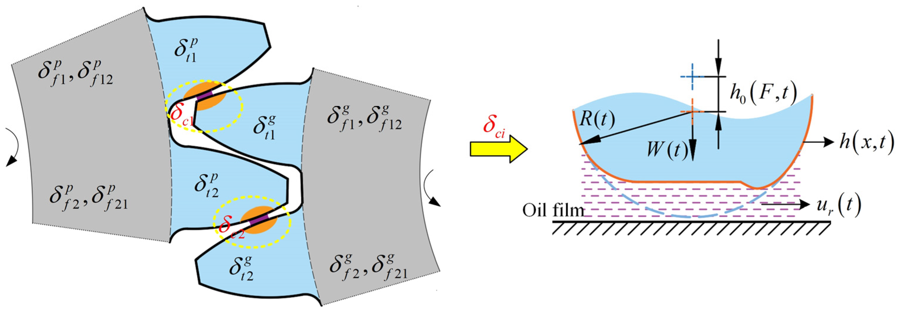
3.1. Deformation Components

The gear can be seen as the non-uniform cantilever beam supported by flexible gear body. The total mesh deformation along the line of action under the applied load of the lubricated gear pair consists of four parts, namely the tooth elastic deformation  δ t , local gear body-induced tooth deformation  δ f , coupling gear body-induced tooth deformation in double-tooth engagement situation  δ f 12 , δ f 21  and the nonlinear local contact deformation  δ c .
The local contact deformation is the main difference between the EHL contact gear pair and the dry contact gear pair. The oil film pressure distribution is different from the Hertzian contact pressure distribution, and the presence of the oil film keeps the two contacting tooth surfaces away from each other (see Figure 1). Therefore, the local contact deformation in this study is equal to the value of subtracting the center oil film thickness from center elastic deformation,
δ c F , t = δ 0 , t h 0 , t = h 0 F , t
where,  δ 0 , t  and  h 0 , t  are expressed in Equation (3), and local contact deformation is nonlinear with the applied load according to the solution of thermal EHL.
The tooth elastic deformation  δ t  consists of the bending deformation  δ b , shearing deformation  δ s  and axial compressive deformation  δ a , and can be described as,
δ t = δ b + δ s + δ a = F / K t = F 1 / K b + 1 / K s + 1 / K a
where,  K t  is defined as gear tooth stiffness;  K b , K s  and  K a  are the bending, shearing and axial compressive stiffness calculated in Ref. [28].
The local gear body-induced tooth deformation is expressed as,
δ f = F / K f
where,  K f  is the fillet foundation stiffness derived in Ref. [29].
Therefore, the total deformation in the single-tooth contact region is obtained by,
δ s i = δ t i p + δ t i g + δ f i p + δ f i g + δ c i F , t
where,  i  represents the  i t h  tooth pair;  p  and  g  represents the pinion and gear, respectively;
For double-tooth contact region, the coupling effect of adjacent teeth should be considered, since two adjacent teeth are coupled with each other through one gear body. As long as elastic deformation exists in the gear body, all the teeth connected will surely be influenced [30]. The gear body structure coupling deflection calculated by Xie et al. [16] is used in this paper. Then, the total deformation of the  i t h  tooth pair in the double-tooth contact region can be represented as follows according to Equations (11)–(13),
δ d 1 = δ t 1 p + δ t 1 g + δ f 1 p + δ f 1 g + δ f 12 p + δ f 12 g + δ c 1 F , t       = F 1 1 / K t 1 p + 1 / K t 1 g + 1 / K f 1 p + 1 / K f 1 g + F 2 1 / K f 12 p + 1 / K f 12 g h 01 F 1 , t δ d 2 = δ t 2 p + δ t 2 g + δ f 2 p + δ f 2 g + δ f 21 p + δ f 21 g + δ c 2 F , t       = F 2 1 / K t 2 p + 1 / K t 2 g + 1 / K f 2 p + 1 / K f 2 g + F 1 1 / K f 21 p + 1 / K f 21 g h 02 F 2 , t
where, subscripts 1 and 2 represent tooth pair 1 and tooth pair 2, respectively;  F i  is the applied load of the  i t h  tooth pair; the structure coupling gear body-induced flexibility  1 / K f 12  represents the flexibility of the mesh point on tooth pair 1 that contributed by  F 1 1 / K f 21  represents the structure coupling flexibility of the mesh point on tooth pair 2 that contributed by  F 2 ; the detailed analytical formulas can be seen in Ref. [16].
It should be mentioned that the above deformation components of the gear pair all vary with the meshing position.

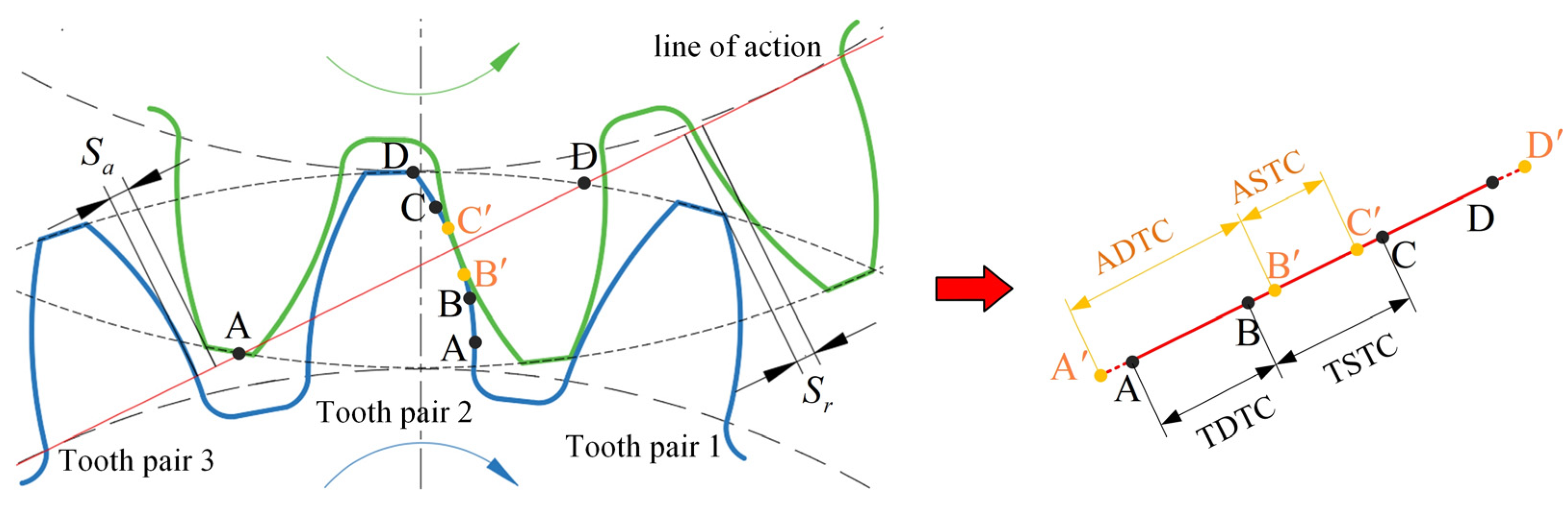
3.2. Extended Tooth Contact

In present study, the complete meshing process of a gear pair is defined as starting with the engagement of tooth tip of the driven gear and ending with the disengagement of tooth tip of the driving gear. Thus, for a standard mounted involute gear pair, the length of theoretical double-tooth contact (TDTC) and single-tooth contact (TSTC) can be calculated according to the geometric parameters,
θ d t = tan arccos r b p / r a p 2 π z p tan arccos r b p / r a g 2 + a 2 2 a r a g cos arccos r b g / r a g α 0 θ s t = 2 π / z p θ d t
where,  r b i  and  r a i ( i = p , g )  represent base circle radius and addendum circle radius of the pinion and gear, respectively;  z p  is tooth number of the pinion;  a  is the gear standard installation center distance;  α 0  is the pressure angle.
However, due to the deformation of the loaded gear pair, the actual contact region will change and the effect of extended tooth contact (ETC) [20] should be considered. As shown in Figure 2, the outgoing tooth pair 1 will keep in contact until tooth pair 2 enters the point  B , later than the theoretical disengagement point B. Similarly, the incoming tooth pair 3 will get into contact when tooth pair 2 enters the point  C , previous to the theoretical engagement point C. Therefore, the actual meshing process of a gear pair is changed to interval  A , D . The actual double-tooth contact region (ADTC) is extended to  A , B  and the actual single-tooth contact region (ASTC) is shortened to  B , C .
In this paper, the angular range of the ETC is defined as  0 , θ 1 B , B  and  0 , θ 2 C , C . Since the ETC occurs near the node of the region of TSTC, the boundary of the ETC, namely  θ 1  and  θ 2 , should be calculated according to the relationship that the loaded static transmission error (LSTE) in single-tooth contact region is equal to the separation distances. The LSTE in single-tooth contact becomes,
δ L S T E S = δ s + e p + e g
where,  δ s  is expressed in Equation (14);  e p  and  e g  are unloaded transmission errors.
The separation distances  S r  and  S a  are the formulas of the separation angle, and are defined as the distance between a pair of teeth just out of contact, during engagement and disengagement, respectively, under the unloaded condition. More derivation details can be obtained in Ref. [31]. According to the above analysis, the implicit functions for  θ 1  and  θ 2  can be obtained according to Equations (14) and (17),
S r θ 1 = F j = p , g 1 / K t j φ 1 + 1 / K f j φ 1 h 0 F , φ 1 + e p + e g S a θ 2 = F j = p , g 1 / K t j φ 2 + 1 / K f j φ 2 h 0 F , φ 2 + e p + e g
where,  φ 1 = θ d t + θ 1 , φ 2 = θ d t + θ s t θ 2 ·  represents the meshing position.
Therefore, the length of ADTC and ASTC can be calculated as,
θ d a = θ d t + θ 1 + θ 2 θ s a = θ s t θ 1 θ 2

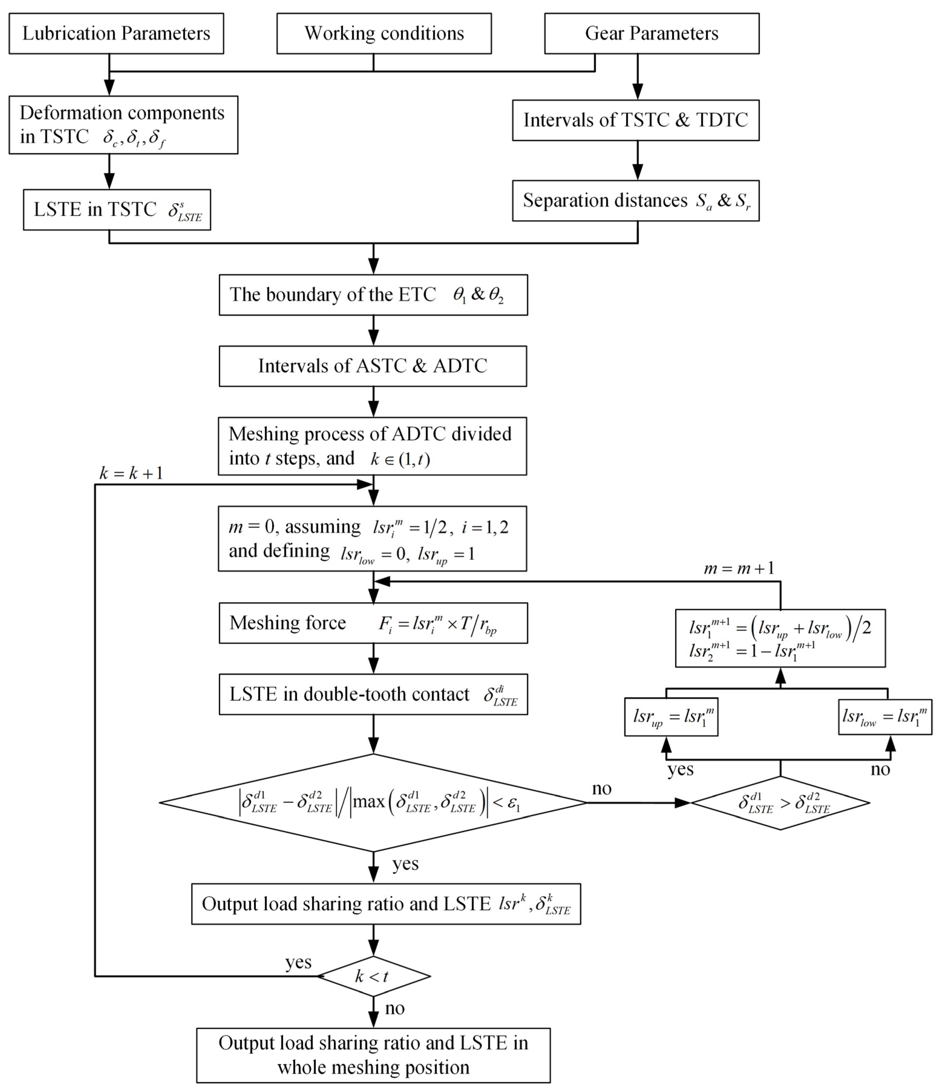
3.3. Load Distribution in Double Tooth Contact

The loaded static transmission error (LSTE) in double-tooth contact region is,
δ L S T E d i = δ d i + e p i + e g i
where,  i  represents the  i t h  tooth pair.
The load distribution in double-tooth contact region is determined by the deformation equilibrium condition, which means that the base pitches of two tooth pair that in simultaneously contact should be equal [22,30]. A more concise expression can be defined as the loaded static transmission error of the meshing tooth pairs must be the same. Hence, the deformation equilibrium equation for TDTC can be represented by,
δ L S T E d 1 δ L S T E d 2 / max δ L S T E d 1 , δ L S T E d 2 < ε 1 F 1 + F 2 = T / r b p
where,  ε 1 = 10 4  is the convergence tolerance to facilitate iterative calculation;  T  is the torque applied on the pinion.
The extended tooth contact (ETC) in the region of TSTC is the special case of double tooth contact, in which the separation distances  S r  and  S a  should be embodied in the calculation of LSTE. Taking the intervals  B , B  and  C , C  as examples, the detailed deformation equilibrium equations can be established according to Equations (15) and (20),
When in the interval  B , B  and  φ 0 , θ 1 ,
δ L S T E d 1 = F 1 j = p , g 1 / K t 1 j φ 1 + 1 / K f 1 j φ 1 + F 2 j = p , g 1 / K f 12 j φ 1 h 01 F 1 , φ 1 + e p 1 + e g 1 δ L S T E d 2 = S r φ + F 2 j = p , g 1 / K t 2 j D + 1 / K f 2 j D + F 1 j = p , g 1 / K f 21 j D h 02 F 2 , D + e p 2 + e g 2
where,  φ 1 = θ d t + φ D  represents the meshing position D.
When in the interval  C , C  and  φ 0 , θ 2 ,
δ L S T E d 1 = F 1 j = p , g 1 / K t 1 j φ 2 + 1 / K f 1 j φ 2 + F 2 j = p , g 1 / K f 12 j φ 2 h 01 F 1 , φ 2 + e p 1 + e g 1 δ L S T E d 2 = S a φ + F 2 j = p , g 1 / K t 2 j A + 1 / K f 2 j A + F 1 j = p , g 1 / K f 21 j A h 02 F 2 , A + e p 2 + e g 2
where,  φ 2 = θ d t + θ s t φ A  represents the meshing position A.

3.4. Iterative Solution Procedure

According to the above analysis, the solution of load distribution is based on the deformation equilibrium condition of the meshing gear pairs. The local contact deformation contained in the LTCA relies on the solution of thermal EHL equations, which in turn requires the calculation of load distribution. Therefore, for EHL contact gear pairs, it is not possible to directly give an intuitive formula for load sharing radio as in previous studies of dry contact gears [20,32], especially when the deformation component is related to operation conditions and lubrication. In order to solve the interdependence of the load distribution and lubrication behavior, a circular iterative solution method needs to be constructed. The detailed iterative solution process is described in Figure 3. It should be mentioned that the proposed method has good compatibility and can also be used to calculate the load distribution of dry contact gear pairs by replacing the local contact deformation  δ c  with linear or nonlinear Hertzian contact deformation, and in which case, the solution of thermal EHL will be omitted.

4. Results and Discussion

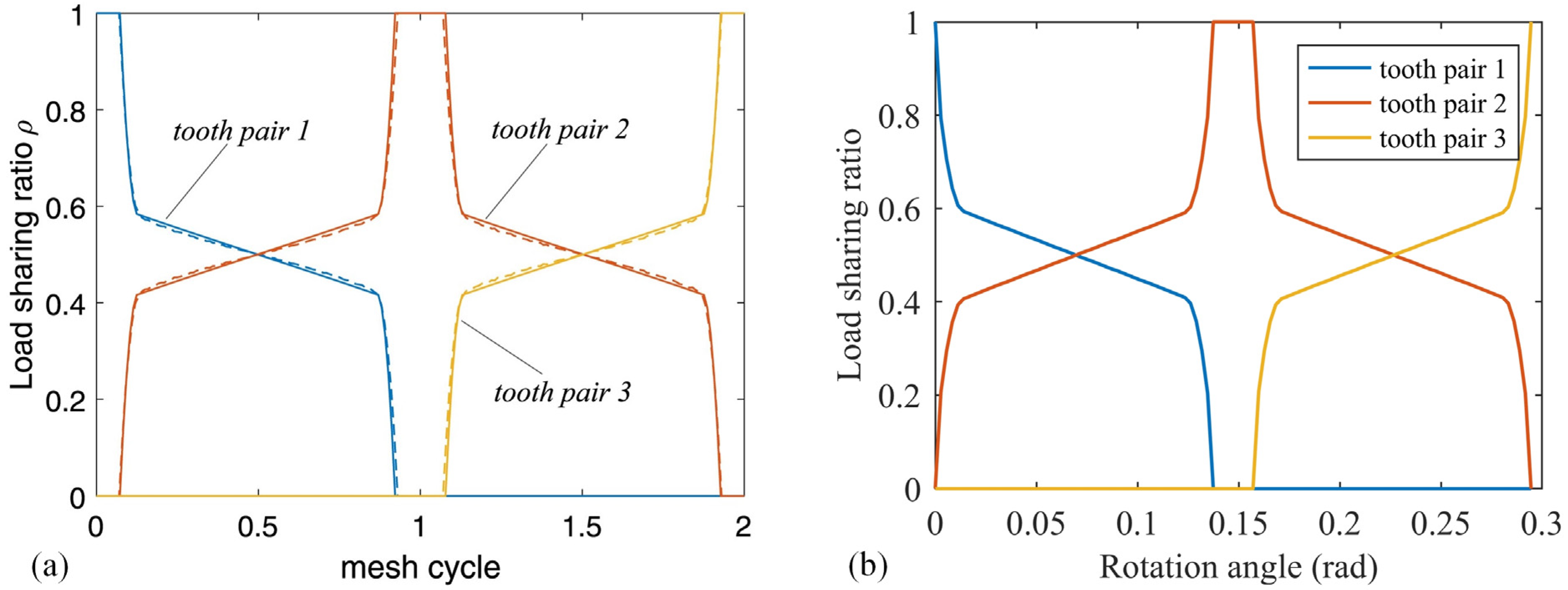
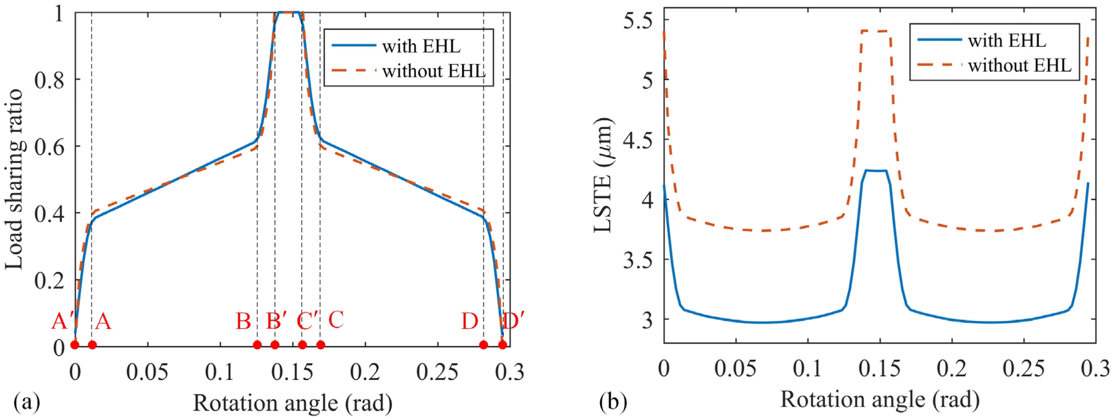
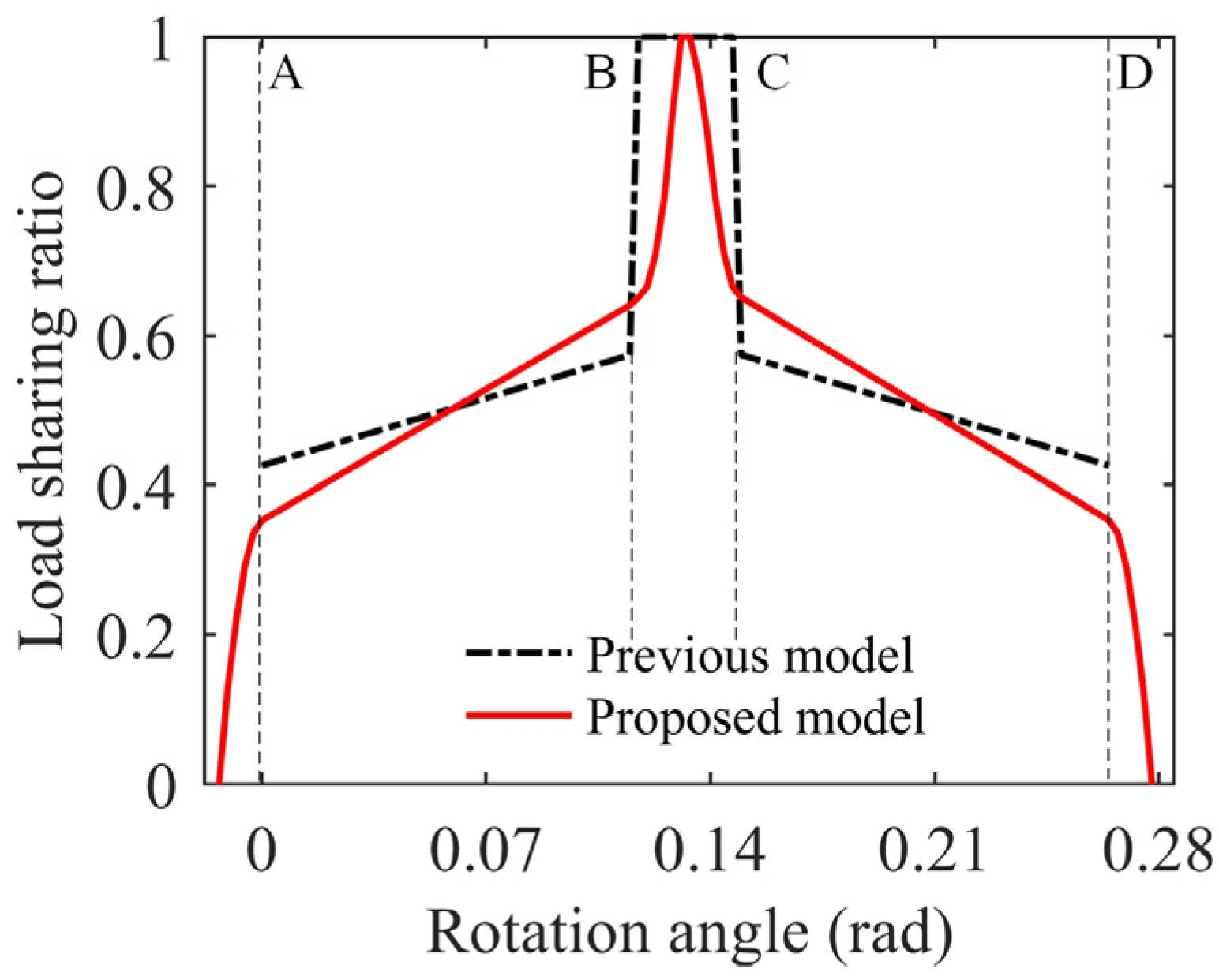
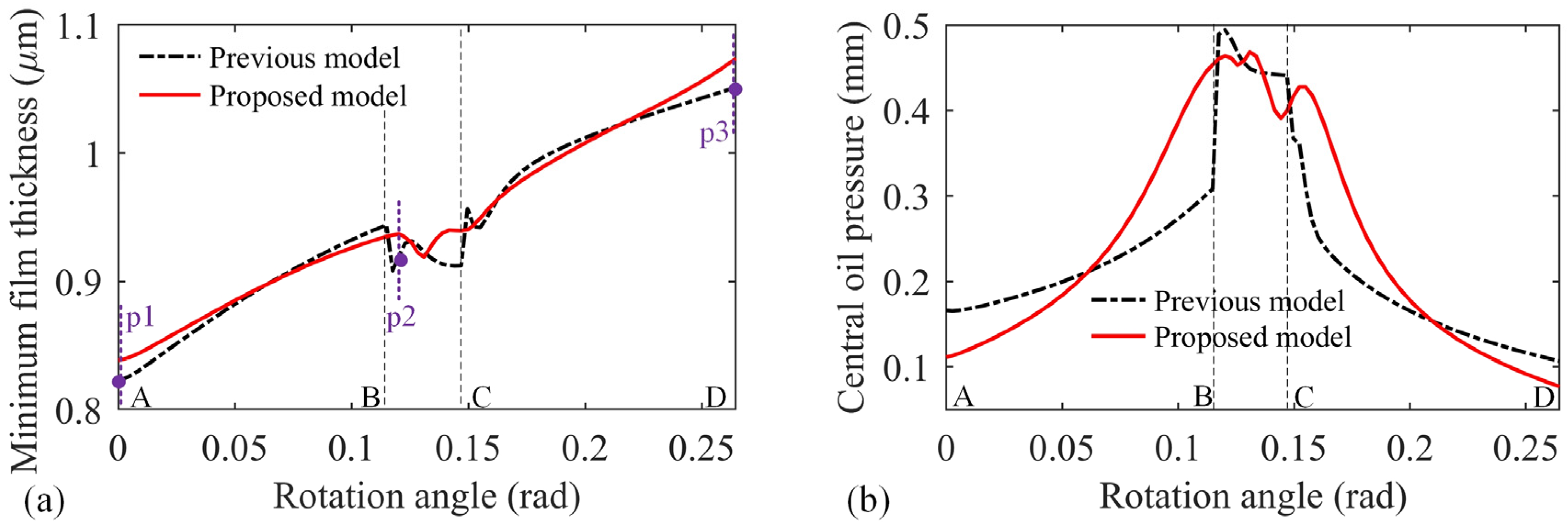
4.1. Model Verification

In this section, the proposed model is verified by comparing the results in previous studies and the difference between the dry contact and EHL contact gear pairs is analyzed. Recently, Zheng et al. [23] developed an analytical load sharing model for dry contact spur gears considering the extended tooth contact, and the predicated result (continuous lines) matches well with the FEM (dashed lines), see Figure 4a. To verify the correctness of the model in this paper, the same geometrical and material properties of the Gear pair A are applied (see details in Appendix A). In order to be consistent with the settings in the reference, the dry contact condition is assumed by setting the local contact as the nonlinear Hertzian contact deformation, that is,  δ c i = 1.275 F i 0.9 / ( E 0.9 L 0.8 ) . By comparing Figure 4a,b, the proposed model has a good agreement with the FEM simulations. This indicates that the model proposed in this study has wide applicability and the load distribution of dry contact gear pairs can be correctly obtained.
The innovation of the proposed solution is the ability to study the load distribution and the LSTE of lubricated gear pairs considering thermal EHL, which was not available in previous studies. The results with and without the consideration of thermal EHL, namely, in thermal EHL contact and in dry contact are further compared in Figure 5. As shown in Figure 5a, the distribution of each interval is consistent with that listed in Section 3.2. The smooth transitions between DTC and STC are clearly reflected in both the lubricated contact (blue continuous line) and dry contact (orange dashed line) gear pairs, and ETC intervals are essentially the same under this geometric parameters and operating conditions. However, the slope of the curve in DTC has a significant change, which indicates that the local contact deformation under the effect of thermal EHL is quite different from the nonlinear Hertzian contact deformation for dry contact. At the beginning of the TDTC (position A), the load sharing ratio of the lubricated contact gear pairs is 0.38, which is slightly lower than that of the dry contact gear pairs (0.41). Similarly, the load sharing ratio of the lubricated contact gear pairs is higher than that of the dry contact gear pairs (0.61 vs. 0.59) at the end of the TDTC (position B). The solution of the load distribution in gear system is an important issue since it determines the calculation of mesh stiffness and lubrication, and consequently affects the dynamic response. Even small differences in load distribution can significantly affect the calculation of LTCA. As shown in Figure 5b, the average LSTE of the EHL contact gear pairs is 23% smaller than that of the dry contact gear pairs. This is due to the presence of the oil film which changes the pressure distribution and affects the mutual distance between the tooth surfaces. Therefore, it is important to consider the effect of thermal EHL into the calculation of load distribution for lubricated gear pairs.

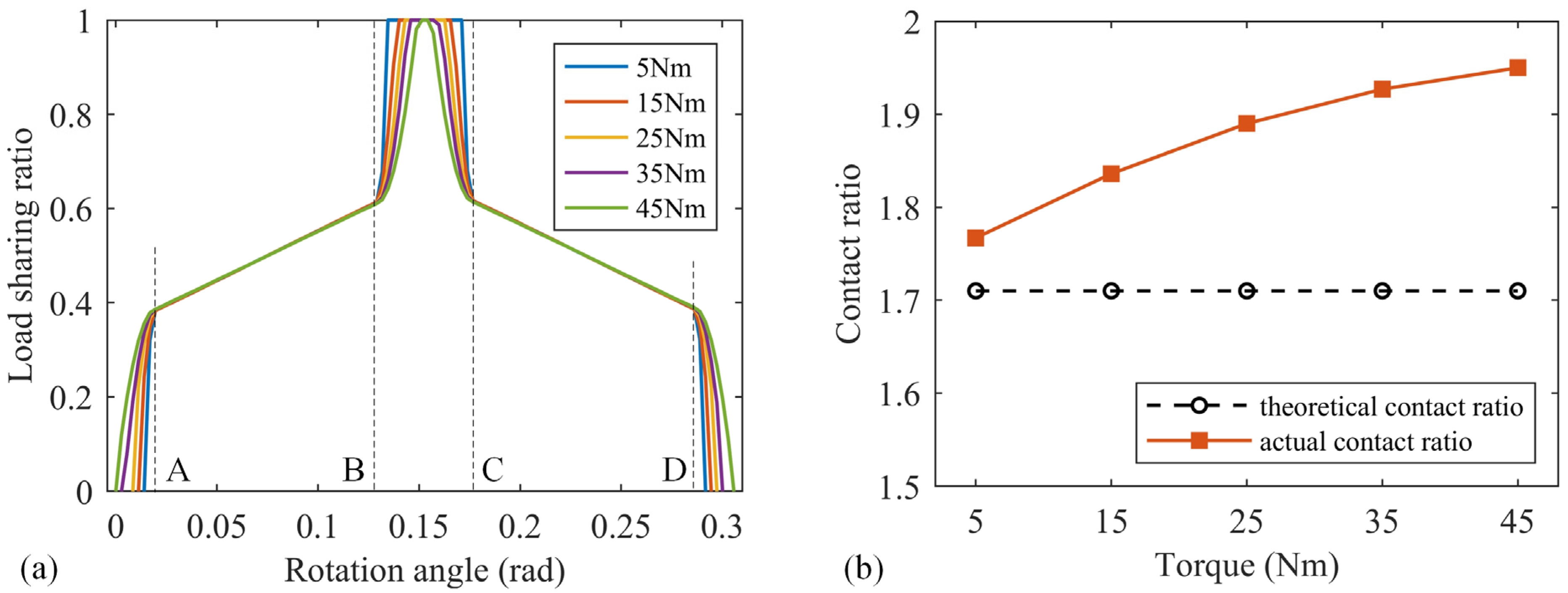
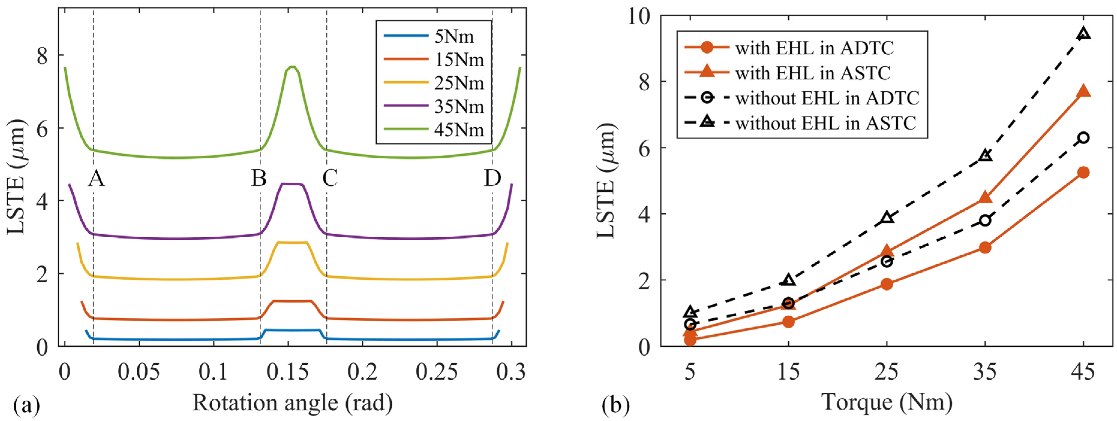
4.2. Effect of Torque on Load Distribution and LSTE

This section compares the load sharing ratio and LSTE under different load torques, respectively. Figure 6a illustrates the variations of load sharing ratio with the increasing torques, and the dashed lines in the figure mark the intervals of the TDTC and TSTC. It can be seen that the change in load sharing ratio in TDCT under different torques is negligible, while the apparent variations are reflected in the region of ETC. The higher the torque applied on the gear pairs, the more significant difference between the actual and theoretical contact conditions, and the transition between DTC and STC becomes smoother. The extended tooth contact is the phenomenon of theoretical separation teeth contact under force. Due to the flexibility of the gear, the deformation of the gear pair increases as the applied force increases, resulting in earlier contact during engagement, and later separation during disengagement. Therefore, the load-dependent ETC influences the meshing intervals of the gear pairs. The actual double-tooth contact region increases and the actual single-tooth contact region decreases with the increasing applied torques, which is further reflected in the calculation of the contact ratio indicated in Figure 6b. The theoretical contact ratio is only related to the gear geometry parameters and does not change with the operating conditions. However, due to the extended tooth contact and gear flexibility, the actual contact ratio increases with the increasing torque, which indicates that the presence of ETC enhances the load-carrying capacity and transmission smoothness of the gear drive. The nonlinear effect of torque on the contact ratio can be observed in Figure 6b. This is due to the complex mechanism of nonlinear local contact deformation and structural coupling deformation on the deformation equilibrium condition with the consideration of thermal EHL. A similar phenomenon of the variation of load sharing ratio and contact ratio with increasing applied torques also appears in dry contact gear pairs, as studied in Refs. [22,23].
The corresponding LSTE curves under different torques are shown in Figure 7. Compared with the variation of loading sharing radio, the LSTE increases more evidently with torque nonlinearity. The variation of LSTE with load is related to the load sharing ratio, nonlinear meshing deformation and deformation coordination equation. To further investigate the effect of thermal EHL on LSTE, Figure 7b compares the LSTE of the dry contact and EHL contact gear pairs. The mean values of the LSTE both increase nonlinearly with the increase in torque. The LSTE in the region of ASTC is higher than that in ADTC, which is due to the better bearing capacity of double tooth contact. The LSTE of the EHL contact gear pair is lower than that of dry contact gear pair, but the effect of lubricant oil film on LSTE decreases with increasing torque both in the region of ADTC and ASTC. The reason is that with the increase in load, the difference between oil film pressure distribution and Hertzian pressure distribution decreases, and the proportion of local contact deformation in total deformation decreases. In other words, for the lightly loaded case, the effect of thermal EHL behavior on LSTE is more obvious and needs to be considered into the iterative solution.

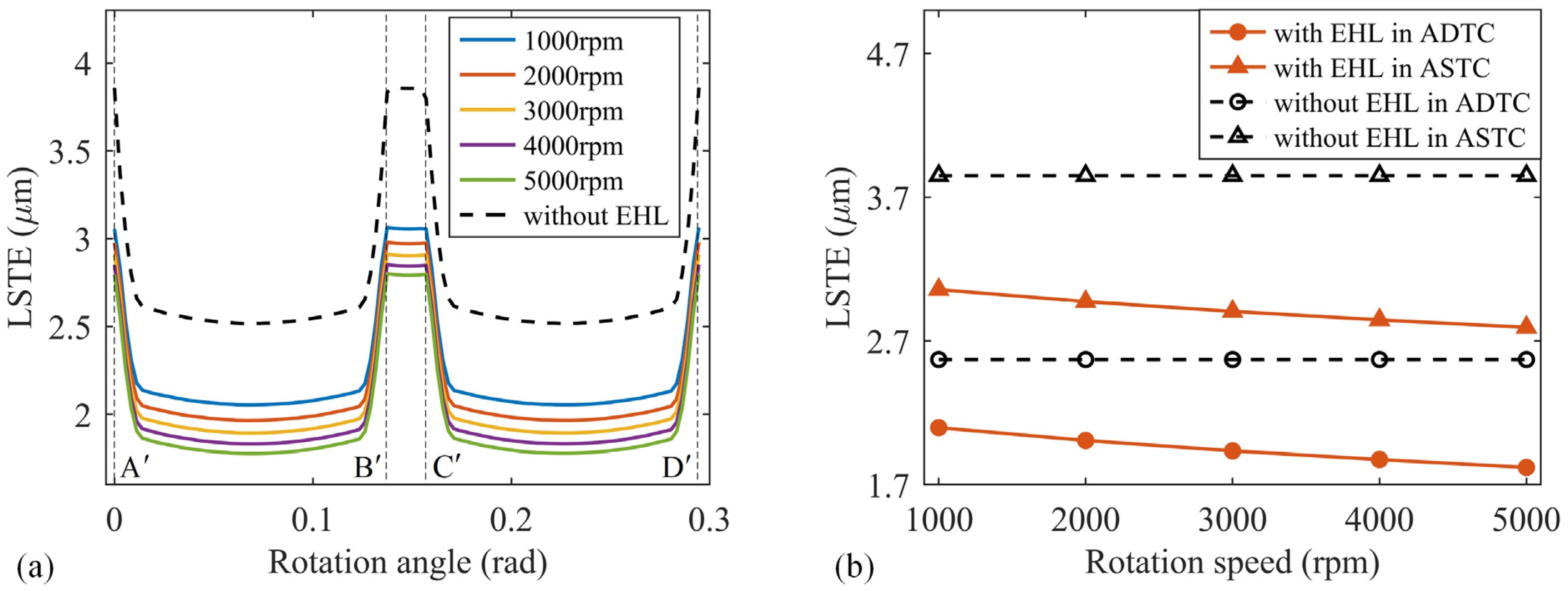
4.3. Effect of Rotation Speed on LSTE

This section investigates the effect of input rotation speed on the LSTE and load distribution. Figure 8 presents a comparison of the LSTE with and without considering the thermal EHL, respectively, obtained under increasing rotation speeds. The dashed lines in Figure 8a represents the intervals of ADTC and ASTC. It can be seen that the actual contact situation remains essentially unchanged at different speeds and the smooth transition in the region of ETC is also consistent, which indicates that the actual contact ratio can be considered as not varying with the rotation speed. The difference between the load sharing ratio with and without considering the thermal EHL is mainly reflected in the curve slope in ADTC interval, which is the same as presented in Figure 5a. The effect of rotational speed on load sharing ratio is not significant for dry contact or thermal EHL condition. However, the difference between the corresponding LSTE is more obvious. The LSTE of dry contact gear pair, that is, without considering thermal EHL, does not change with the rotation speed, which is consistent with previous model simulation results. This is because the deformation components of the dry contact tooth pair are all independent of the rotation speed, especially for calculation of Hertzian contact deformation under dry contact condition. However, the LSTE of EHL contact gear pair decreases with the increasing rotation speed and this phenomenon was not reflected in previous studies. The reason is that the central oil film thickness increases significantly with the increasing input velocity, but the oil film pressure distribution change inapparent, resulting in the reduction in local contact deformation. In other words, as the rotational speed increases, more lubricant is wrapped into the contact zone, causing the contact tooth surfaces to move away from each other and offsetting some of the elastic deformation. The local contact deformation is even negative when the rotation speed is high enough. The influence of rotation speed is further studied by comparing the average value of LSTE in single and double tooth contact region between the dry contact and EHL contact gear pairs. Figure 8b shows that the LSTE with the consideration of thermal EHL is nonlinearly influenced by the rotation speed both in the region of ADTC and ASTC. The attenuation of the LSTE gradually flattens out at higher speed, which indicates that the increase in oil film thickness is limited. Since the LSTE of dry contact tooth pairs remains constant with the speed, this means that the influence of EHL condition at high rotation speed is more pronounced and should be given more attention.

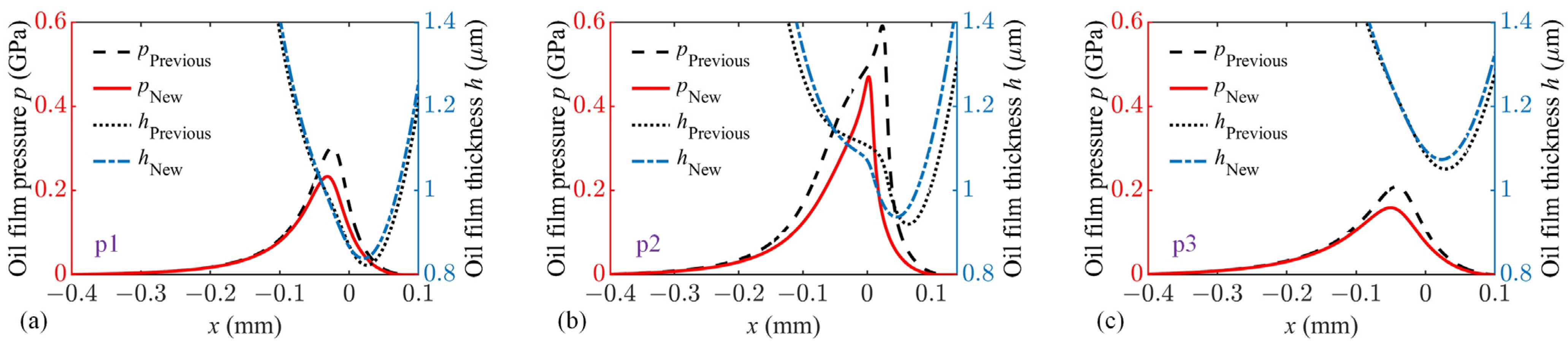
4.4. Influence of EHL Load Distribution Model on Lubrication Behavior

In previous literature on characteristics of gear contact elastohydrodynamic lubrication, such as transient lubrication behavior [3,11], modeling and solving of oil film stiffness and damping [5,33,34] and tribo-dynamic response [6,35], the load spectrums of the gear drive are simple settings without considering the effect of extended tooth contact and EHL contact. Since the transient behavior is mainly due to the squeezing and pumping effects caused by sudden load changes, it is necessary to use a more reliable load distribution model to study gear transmission lubrication behavior. Taking the case of gear parameters and lubricant properties in Ref. [35] for comparison to investigate the effect of the proposed load distribution model on gear drive lubrication behavior. The detailed parameters are listed in Appendix as Gear pair B.
Figure 9 compares the load sharing ratio obtained by the model proposed in this paper with the traditional model used in Ref. [35]. The traditional model displayed in black dashed line simplified the compliance of the meshing tooth pair to facilitate the calculation of LSTE, which can only reflect the sudden change in the alternating contact of single and double tooth. However, the load sharing ratio in red line for the proposed model shows smooth transition between the region of STC and DTC due to effect of ETC. The change in the slope of the curve in DTC region indicates that EHL contact of the gear drive leads one of the two meshing teeth to carry on a larger load at the engagement point and at the junction of single and double tooth contact. The overall load sharing ratio varies gradually rather than abruptly. This obvious difference in load sharing ratio indicates that the proposed model is necessary. In order to facilitate comparison, only the curves from theoretical approach point (position A) to theoretical recession point (position D) are considered. The non-Newtonian transient thermal EHL problem for the given spur gear transmission is solved by different load distribution models, and results of minimum oil film thickness and central oil pressure are shown in Figure 10. In the region of DTC, due to the difference in the values of load sharing ratio obtained from different models, the central oil film pressure and the minimum oil film thickness reflect similar fluctuations in variation. It should be noted that the change trend of oil film pressure and oil film thickness is opposite, that is, the oil film thickness decreases at the contact position where the film pressure becomes greater and vice versa. At the alternating position of theoretical double-tooth and single-tooth contact, that is, position B and C, the oil film thickness and central film pressure have transient changes for both proposed model and previous model due to the squeezing and pumping effects included in Reynold equation. However, this transient effect embodied by the proposed model lags compared to previous model due to the delayed disengagement of double tooth contact. Moreover, the transient variations in the proposed model are smoother both reflected in film thickness and pressure due to the smooth transition between the single-tooth and double-tooth contact caused by ETC. This phenomenon indicates that the extended tooth contact has a significant impact on the lubrication characteristics of gear drives and needs to be considered. To further study the difference, the characteristic positions p1, p2 and p3 are taken to calculate the contact pressure distribution and oil film thickness respectively for comparison. As shown in Figure 11, the results of pressure distribution and film thickness obtained by different models are different at any position, which indicates that the load distribution significantly affects the thermal EHL behavior. Therefore, in order to accurately study the characteristics of thermal EHL of gear transmission, a more reasonable load distribution model needs to be constructed.

5. Conclusions

In this study, an improved analytical load distribution model for the EHL contact spur gear pair is proposed, which supplements the blank of research on gear transmission thermal EHL characteristics. The proposed model is established based on a circulation iteration method with the consideration of thermal EHL behavior, flexibility of the gear tooth, structural coupling deformation of the gear body, extended tooth contact and deformation compatibility condition. The variations of load sharing ratio, loaded static transmission error, contact ratio at different torques and rotation speeds are investigated. The lubrication characteristics obtained with different load distribution models are compared. Some contributions of this study are shown as follows:
  • The load sharing ratio predicted by the proposed model for dry contact gear drive is consistent with the FEM simulation results presented in previous research, which proves the correctness and universality of the proposed analytical model;
  • The load sharing ratio, LSTE and contact ratio of the gear pair vary significantly with the applied torque due to the effect of extended tooth contact. The influence of thermal EHL contact is more obvious for the lightly loaded case;
  • With the changes in rotation speed, the LSTE shows evident variation due to the sensitivity of oil film thickness to speed. The influence of thermal EHL contact at high rotation speed is more pronounced;
  • There is a significant coupling effect between the load distribution and thermal EHL solution. Therefore, the thermal EHL solution should be calculated iteratively in the load distribution model for the EHL contact gear pairs. Similarly, the accurate analysis of transient thermal EHL behavior for gear transmission requires a matching load distribution model.

Author Contributions

Conceptualization, R.L. and W.T.; Methodology, R.L. and Q.H.; Software, R.L. and J.X.; Validation, R.L. and Q.H.; Formal analysis, R.L.; Investigation, R.L.; Resources, R.L. and J.X.; Data curation, R.L. and J.X.; Writing—original draft, R.L.; Writing—review & editing, R.L.; Visualization, R.L.; Supervision, W.T.; Project administration, W.T.; Funding acquisition, W.T. All authors have read and agreed to the published version of the manuscript.

Funding

This research was funded by National Key R & D Program of China, grant number No. 2020YFB2008102.

Data Availability Statement

Data sharing is not applicable to this article.

Conflicts of Interest

The authors declare no conflict of interest.

Appendix A

Table A1. Main parameters of the gear pair and lubricant.
ParametersGear Pair AGear Pair B
PinionGearPinionGear
Tooth number  z  40404286
Modules  m  (mm)112.52.5
Tooth width  L  (mm)20203030
Pressure angle  α 0  (°)20202020
Elastic modulus  E  (GPa)206.8206.8210210
Poisson’s ratio  ν  0.30.30.30.3
Tip clearance coefficient0.250.250.250.25
Addendum coefficient1111
Torque on pinion  T p  (Nm)5–45-100-
Rotation speed of pinion  n p  (rpm)1000–5000-2000-
Characteristic shear stress  τ 0  (MPa)1010
Ambient density of lubricant  ρ 0  (kg/m3)870870
Ambient viscosity of lubricant  η 0  ( Pa s )0.030.06
Ambient temperature  T 0  (K)313313
Specific heat of lubricant  c o  (J/(kg K))20002000
Thermal conductivity of lubricant  k o  (W/(m·K))0.140.14

References

  1. Dowson, D.; Higginson, G.R. A Numerical Solution to the Elasto-Hydrodynamic Problem. J. Mech. Eng. Sci. 1959, 1, 6–15. [Google Scholar] [CrossRef]
  2. Larsson, R. Transient non-Newtonian elastohydrodynamic lubrication analysis of an involute spur gear. Wear 1997, 207, 67–73. [Google Scholar] [CrossRef]
  3. Wang, Y.Q.; Li, H.Q.; Tong, J.W.; Yang, P.R. Transient thermoelastohydrodynamic lubrication analysis of an involute spur gear. Tribol. Int. 2004, 37, 773–782. [Google Scholar] [CrossRef]
  4. Zhou, C.; Xiao, Z.; Chen, S.; Han, X. Normal and tangential oil film stiffness of modified spur gear with non-Newtonian elastohydrodynamic lubrication. Tribol. Int. 2017, 109, 319–327. [Google Scholar] [CrossRef]
  5. Xiao, Z.; Li, Z.; Shi, X.; Zhou, C. Oil Film Damping Analysis in Non-Newtonian Transient Thermal Elastohydrodynamic Lubrication for Gear Transmission. J. Appl. Mech.-Trans. Asme 2018, 85, 035001. [Google Scholar] [CrossRef]
  6. Xiao, Z.; Zhou, C.; Chen, S.; Li, Z. Effects of oil film stiffness and damping on spur gear dynamics. Nonlinear Dyn. 2019, 96, 145–159. [Google Scholar] [CrossRef]
  7. Liu, H.; Liu, H.J.; Zhu, C.C.; Parker, R.G. Effects of lubrication on gear performance: A review. Mech. Mach. Theory 2020, 145, 103701. [Google Scholar] [CrossRef]
  8. Zhou, W.G.; Zhu, R.P.; Liu, W.Z.; Shang, Y.W. An Improved Dynamic Transmission Error Model Applied on Coupling Analysis of Gear Dynamics and Elastohydrodynamic Lubrication. J. Tribol.-Trans. Asme 2022, 144, 051601. [Google Scholar] [CrossRef]
  9. Yang, X.K.; Tofighi-Niaki, E.; Zuo, M.J.; Tian, Z.G.; Safizadeh, M.S.; Qin, D.L. Analysis of spur gearbox dynamics considering tooth lubrication and tooth crack severity progression. Tribol. Int. 2023, 178, 108027. [Google Scholar] [CrossRef]
  10. Huangfu, Y.F.; Dong, X.J.; Chen, K.K.; Peng, Z.K. Coupling mechanism between systematic elastic deformation and gear surface damage. Int. J. Mech. Sci. 2023, 238, 107850. [Google Scholar] [CrossRef]
  11. Li, S.; Kahraman, A. A Transient Mixed Elastohydrodynamic Lubrication Model for Spur Gear Pairs. J. Tribol.-Trans. Asme 2010, 132, 011501. [Google Scholar] [CrossRef]
  12. Chen, M.; Xiong, X.; Zhuang, W. Design and Simulation of Meshing Performance of Modified Straight Bevel Gears. Metals 2021, 11, 33. [Google Scholar] [CrossRef]
  13. Sanchez, M.B.; Pleguezuelos, M.; Pedrero, J.I. Approximate equations for the meshing stiffness and the load sharing ratio of spur gears including hertzian effects. Mech. Mach. Theory 2017, 109, 231–249. [Google Scholar] [CrossRef]
  14. Marques, P.M.T.; Martins, R.C.; Seabra, J.H.O. Power loss and load distribution models including frictional effects for spur and helical gears. Mech. Mach. Theory 2016, 96, 1–25. [Google Scholar] [CrossRef]
  15. Chen, Z.; Shao, Y. Mesh stiffness calculation of a spur gear pair with tooth profile modification and tooth root crack. Mech. Mach. Theory 2013, 62, 63–74. [Google Scholar] [CrossRef]
  16. Xie, C.; Hua, L.; Han, X.; Lan, J.; Wan, X.; Xiong, X. Analytical formulas for gear body-induced tooth deflections of spur gears considering structure coupling effect. Int. J. Mech. Sci. 2018, 148, 174–190. [Google Scholar] [CrossRef]
  17. Xie, C.; Hua, L.; Lan, J.; Han, X.; Wan, X.; Xiong, X. Improved analytical models for mesh stiffness and load sharing ratio of spur gears considering structure coupling effect. Mech. Syst. Signal Process. 2018, 111, 331–347. [Google Scholar] [CrossRef]
  18. Lu, R.; Tang, W. Analytical calculation models for mesh stiffness and backlash of spur gears under temperature effects. Proc. Inst. Mech. Eng. Part C J. Mech. Eng. Sci. 2021, 236, 4450–4462. [Google Scholar] [CrossRef]
  19. Tse, D.; Lin, H. Separation distance and static transmission error of involute spur gears. In Proceedings of the 28th Joint Propulsion Conference and Exhibit, Nashville, TN, USA, 6–8 July 1992; p. 3490. [Google Scholar]
  20. Ma, H.; Zeng, J.; Feng, R.; Pang, X.; Wen, B. An improved analytical method for mesh stiffness calculation of spur gears with tip relief. Mech. Mach. Theory 2016, 98, 64–80. [Google Scholar] [CrossRef]
  21. Chen, Z.; Ji, P. Study on wear in spur gears based on an improved load distribution model considering the effects of corner contact. Eng. Fail. Anal. 2020, 115, 104605. [Google Scholar] [CrossRef]
  22. Wang, Q.; Wang, Q.; Gui, L.; Fan, Z. Load distribution analysis considering corner contact effects to predict the mechanical efficiency of spur gears. Proc. Inst. Mech. Eng. Part C J. Mech. Eng. Sci. 2022, 236, 7546–7559. [Google Scholar] [CrossRef]
  23. Zheng, X.; Hu, Y.; He, Z.; Xiao, Y.; Zhang, X. On the extended tooth contact and nonlinear dynamics for spur gears-An analytical model. Mech. Mach. Theory 2022, 175, 104958. [Google Scholar] [CrossRef]
  24. Roelands, C.J.A.; Vlugter, J.C.; Waterman, H.I. The Viscosity-Temperature-Pressure Relationship of Lubricating Oils and Its Correlation with Chemical Constitution. Asme J. Basic Eng. 1963, 85, 601. [Google Scholar] [CrossRef]
  25. Yang, P.; Wen, S. A Generalized Reynolds Equation for Non-Newtonian Thermal Elastohydrodynamic Lubrication. J. Tribol.-Trans. Asme 1990, 112, 631. [Google Scholar] [CrossRef]
  26. Qin, W.; Chao, J.; Duan, L. Study on stiffness of elastohydrodynamic line contact. Mech. Mach. Theory 2015, 86, 36–47. [Google Scholar] [CrossRef]
  27. Dowson, D.; Higginson, G.R. Elastohydrodynamic Lubrication: The Fundamentals of Roller and Gear Lubrication; Pergamon Press: Oxford, UK, 1966. [Google Scholar]
  28. Tian, X. Dynamic Simulation for System Response of Gearbox Including Localized Gear Faults; University of Alberta: Edmonton, AB, Canada, 2004. [Google Scholar]
  29. Sainsot, P.; Velex, P.; Duverger, O. Contribution of gear body to tooth deflections—A new bidimensional analytical formula. J. Mech. Des. 2004, 126, 748–752. [Google Scholar] [CrossRef]
  30. Xie, C.; Shu, X. A new mesh stiffness model for modified spur gears with coupling tooth and body flexibility effects. Appl. Math. Model. 2021, 91, 1194–1210. [Google Scholar] [CrossRef]
  31. Lin, H.; Wang, J.; Oswald, F.; Coy, J. Effect of extended tooth contact on the modeling of spur gear transmissions. In Proceedings of the 29th Joint Propulsion Conference and Exhibit, Monterey, CA, USA, 28–30 June 1993. [Google Scholar]
  32. Ma, H.; Pang, X.; Feng, R.; Zeng, J.; Wen, B. Improved time-varying mesh stiffness model of cracked spur gears. Eng. Fail. Anal. 2015, 55, 271–287. [Google Scholar] [CrossRef]
  33. Zhou, C.; Xiao, Z. Stiffness and damping models for the oil film in line contact elastohydrodynamic lubrication and applications in the gear drive. Appl. Math. Model. 2018, 61, 634–649. [Google Scholar] [CrossRef]
  34. Pei, J.; Han, X.; Tao, Y. An improved stiffness model for line contact elastohydrodynamic lubrication and its application in gear pairs. Ind. Lubr. Tribol. 2020, 72, 703–708. [Google Scholar] [CrossRef]
  35. Li, Z.; Zhu, C.; Liu, H.; Gu, Z. Mesh stiffness and nonlinear dynamic response of a spur gear pair considering tribo-dynamic effect. Mech. Mach. Theory 2020, 153, 103989. [Google Scholar] [CrossRef]
Figure 1. Deformation component of lubricated spur gear transmission.
Lubricants 11 00177 g001
Figure 2. The extended tooth contact, theoretical and actual contact intervals.
Lubricants 11 00177 g002
Figure 3. Flowchart of iterative calculation of the proposed load distribution model.
Lubricants 11 00177 g003
Figure 4. Load sharing ratio calculated in previous study and by the proposed model for dry contact gear pair A ( R int  = 8 mm,  T p  = 25 Nm) (a) The predicted values and FEM in Ref. [23]; (b) The calculation results by the proposed model.
Lubricants 11 00177 g004
Figure 5. Comparison of load sharing ratio and LSTE with and without considering the effect of EHL by the proposed model for gear pair A ( R int  = 8 mm,  T p  = 25 Nm,  n p  = 2000 rpm). (a) Load sharing ratio; (b) LSTE.
Lubricants 11 00177 g005
Figure 6. Comparison of load sharing ratio and contact ratio obtained at different torques for gear pair A ( R int  = 12 mm,  n p  = 3000 rpm). (a) Load sharing ratio; (b) Contact ratio.
Lubricants 11 00177 g006
Figure 7. Comparison of LSTE obtained at different torques for gear pair A (a) LSTE; (b) The mean values of LSTE with and without considering EHL.
Lubricants 11 00177 g007
Figure 8. Comparison of LSTE obtained at different rotation speeds for gear pair A ( R int  = 12 mm,  T p  = 20 Nm) (a) LSTE; (b) The mean values of LSTE with and without considering EHL.
Lubricants 11 00177 g008
Figure 9. Comparison of load sharing ratio obtained by different models.
Lubricants 11 00177 g009
Figure 10. Comparison of oil film thickness and pressure along the line of action obtained by different models. (a) Minimum film thickness, (b) Central oil pressure.
Lubricants 11 00177 g010
Figure 11. Comparison of oil film pressure and thickness obtained by different models at different position (a) approach point p1, (b) position p2 near the pitch point, (c) recession point p3.
Lubricants 11 00177 g011
Disclaimer/Publisher’s Note: The statements, opinions and data contained in all publications are solely those of the individual author(s) and contributor(s) and not of MDPI and/or the editor(s). MDPI and/or the editor(s) disclaim responsibility for any injury to people or property resulting from any ideas, methods, instructions or products referred to in the content.

