Article

Mechanical and Tribological Behaviors of U75VG Rail Flash−Butt Welded Joint

1
State Key Laboratory of Performance Monitoring and Protecting of Rail Transit Infrastructure, East China Jiaotong University, Nanchang 330013, China
2
Traction Power State Key Laboratory, Southwest Jiaotong University, Chengdu 610031, China
*
Author to whom correspondence should be addressed.
Lubricants 2023, 11(2), 41; https://doi.org/10.3390/lubricants11020041
Submission received: 20 December 2022 / Revised: 23 January 2023 / Accepted: 25 January 2023 / Published: 27 January 2023
(This article belongs to the Special Issue Advances in Contact Mechanics)

Abstract

:
Flash−butt welded rail is widely used in railway transportation; however, the welded joint is vulnerable after a long time of service, and its damage mechanism is controversial. Here, tensile and reciprocating friction tests were carried out to analyze the mechanical and tribological behaviors between the welded joint and the base metal of a U75VG rail. The results show that flash−butt welding promotes the pearlite to transform into ferrite, leading to a relatively low hardness value but high plasticity. In addition, the yielding and strength of the all−weld−metal specimen are 385 MPa and 1090 MPa, respectively, which are about 24.51% and 7.63% lower than that of the base metal specimen. It is worth noting that the elongation of the all−weld−metal specimen is 57.1% higher than that of the base metal specimen, and more dimples and tearing ridges can be detected on the fracture morphology of the all−weld−metal specimen, while the fracture morphology of the base metal specimen is filled with shallow dimples and cleavage planes. Moreover, the weld metal has a relatively higher COF (coefficient of friction), and its fluctuation amplitude is 1.25 times higher than that of the base metal, which is due to the rougher worn surface. Furthermore, the introduction of flash−butt welding changes the wear mechanism of the U75VG rail from adhesive wear and oxidation to fatigue wear and slight oxidation, and ultimately leads to more serious damage.

1. Introduction

The key role of the railway transportation site is the rail, which, in normal service, guarantees train guidance, traction, and braking. A continuous welded rail makes the high−speed and heavy axle load of the train develop rapidly, leading to the need for higher welding quality. Currently, most rail manufacturers use flash−butt welding [1], and flash−butt welded rails are widely used in railway transportation. However, the welded joint becomes vulnerable with long−time service, and its damage mechanism is controversial [2]. Moreover, the microstructure and characteristics of welded rail joints are greatly different from those of the base metal, resulting in crushing, fracture, and bending deformation of the welded joints [3,4,5,6]. In other words, the failure of the welded rail joints will lead to abnormal contact between the wheel and rail. Subsequently, the vertical acceleration of the train suddenly increases, affecting passenger comfort and endangering traffic safety [7].
At present, much of the research has focused on the damage mechanism of a rail’s flash−butt welded joints. On the one hand, some scholars have tested the performance of treated rail and analyzed the microstructure evolution, mechanical properties, and fatigue fracture mechanisms of laser shock peening and corrosive environments [8,9]. On the other hand, there are other scholars who established finite element models of welded rail joints based on different working conditions, to simulate damage behavior. A significant body of research results show that factors, such as vehicle speed, axle load, joint height, residual stress, and rail roughness, have great influence on the plastic deformation, crack behavior, and stress–strain behaviors of welded rail joints [10,11,12,13]. Zhao et al. [14] studied the significant stress concentration in welded rail joints due to the impact effect. Their research showed that the distribution of an equivalent plastic strain in weld metal, heat−affected zones, and base metal is uneven during wheel–rail rolling contact. Xu et al. [10] pointed out that the maximum load on welded rail joint during wheel–rail rolling contact is 4–12 times that under quasi−static conditions, and the maximum contact pressure, maximum equivalent stress and equivalent plastic strain increase with the train axle load and the running speed. They obtained the mechanical parameters of welded rail joint by static tests, modified the rail dynamic constitutive finite element model, and obtained the simulation results of welded rail joint in wheel–rail rolling contact. Prakash et al. [15,16] also stated that the friction between wheel and rail increases with the adhesion coefficient, the increase of stress intensity factor leads to an increase of crack enlargement and the fatigue life decrease with weld length. This conclusion is obtained by simulating the crack behavior of rail under different working conditions. Besides, welded rail joint is the easy failure part due to defects such as structural changes, inclusions, and pores [17]. Thus, welded rail joint is more prone to collapse, fracture, serious wear, and other damage problems resulting in continuous welded rail appearing irregularly.
And besides, two−point contact of the wheel–rail is likely to occur when the train passes through the curved section. Sliding friction occurs between the wheel rim and rail head side, resulting in the frictional shear stress on the rail will be significantly higher than that in rolling contact [18]. Based on current research, few reports are on the reciprocating friction test of rail weld joints, and carrying out tribological tests of welded rail joint is of great significance.
In this paper, the reciprocating friction and wear test of U75VG rail weld metal and base metal was carried out. Focusing on the microstructure, mechanical properties, and surface damage behavior of weld and base metal reveals the damage mechanism.

2. Experimental Details

2.1. Experimental Materials

The U75VG is usually used for high−speed trains in China. In this paper, the U75VG welded rail joint was conducted by a flash−butt welding machine. In order to rail weld joint with good quality, the welding process parameters are selected, as shown in Table 1. The specimens of tensile and tribological tests were extracted from the welded rail joint and the base metal (head of U75VG rail, shown in Figure 1).
GCr15 steel balls (GB/T18254−2002) with a diameter of 6 mm and surface roughness (Ra) of 0.04 mm were used as the counter−bodies, and the chemical element content is shown in Table 2 and Table 3, respectively. All the tests were repeated three times for the same test parameter to reduce inevitable errors and ensure the reliability of the test results.

2.2. Experimental Method

The tribological test was conducted on a self−made, multi−functional friction and wear testing machine (UNT−3, shown in Figure 2a), and the load, frequency, and duration time of the friction test were 10 N, 2 Hz, and 3 h, respectively. The experiment was conducted in an atmospheric environment (T = 25 °C, RH = 60%). The specimens were cleaned using an ultrasonic cleaner before and after the test. The tensile test by the tension–torsion multi−axis electric servo fatigue testing machine (Walter + BaiLFV−100−HH, 100 KN) and the size of tensile test specimens are shown in Figure 2b.
The specimens were prepared by polishing and etching in a 4% nitric acid and alcohol solution. Then, the microstructure on the cross−section was observed using an optical microscope. The nano−indentation tests on the cross−section were analyzed on a nano indenter using a Berkovich diamond indenter with a constant loading–unloading rate of 30 mN/min. The surface morphologies were observed with a scanning electron microscope, and components of the worn surface were detected through energy−dispersive spectroscopy. The 3D topographies and surface roughness were observed with a white light interferometer.

3. Results

3.1. Microstructure and Mechanical Characteristic

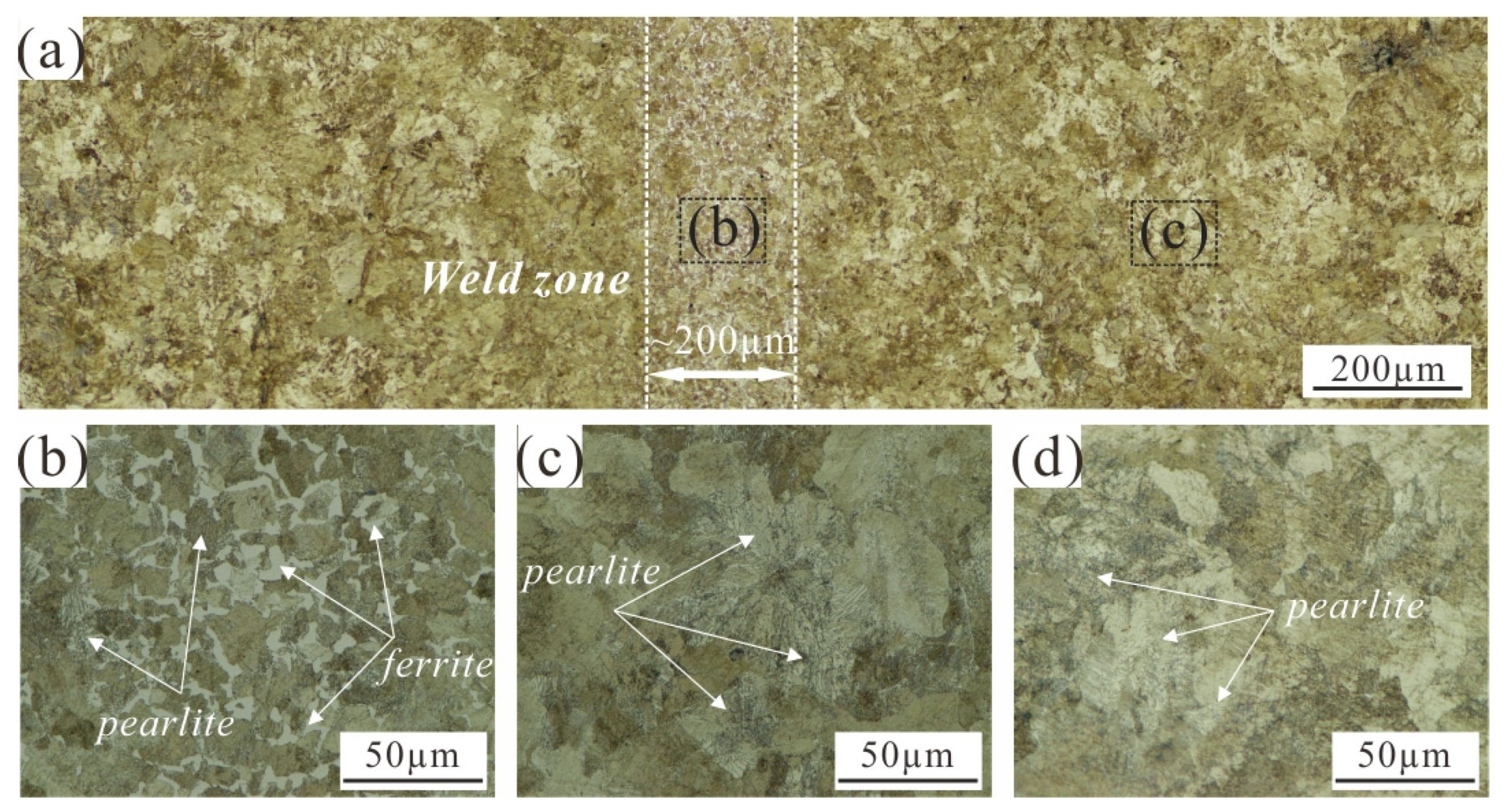
Figure 3 displays the microstructure of weld and base metals of a U75VG rail. There are significant differences between the weld and base metals. The length of the weld metal is about 200 μm and has a large amount of ferrite (Figure 3a), and the Figure 3b,c are the enlarged graph of the Figure 3a, respectively. According to field test and finite element simulations [2,17,19,20], the temperature value differs in different regions in the rail welding process, and the temperature of the weld metal will exceed 1000 °C, resulting in the pearlite transforming into austenite. Moreover, for weld metals, the austenite decomposes into pearlite and ferrite during cooling. Thus, the weld metal has a large amount of ferrite; however, the temperature of the heat−affected zone and base metal does not exceed Ac3, resulting in a significant reduction in the amount of ferrite in the heat−affected zone (Figure 3a), with the main microstructure in the base metal being lamellar pearlite (Figure 3c). Simultaneously, the temperature, grain growth rate, and nucleation rate in different regions of the weld metal pool are not very different, leading to the ferrite in the weld center being more uniform [21]. In any case, to confirm that the microstructure of the base metal of about 500 μm is not affected too much by welding, it is found that the base metal of about 500 μm is the same morphology as 20 cm from the weld zone (Figure 3c,d).
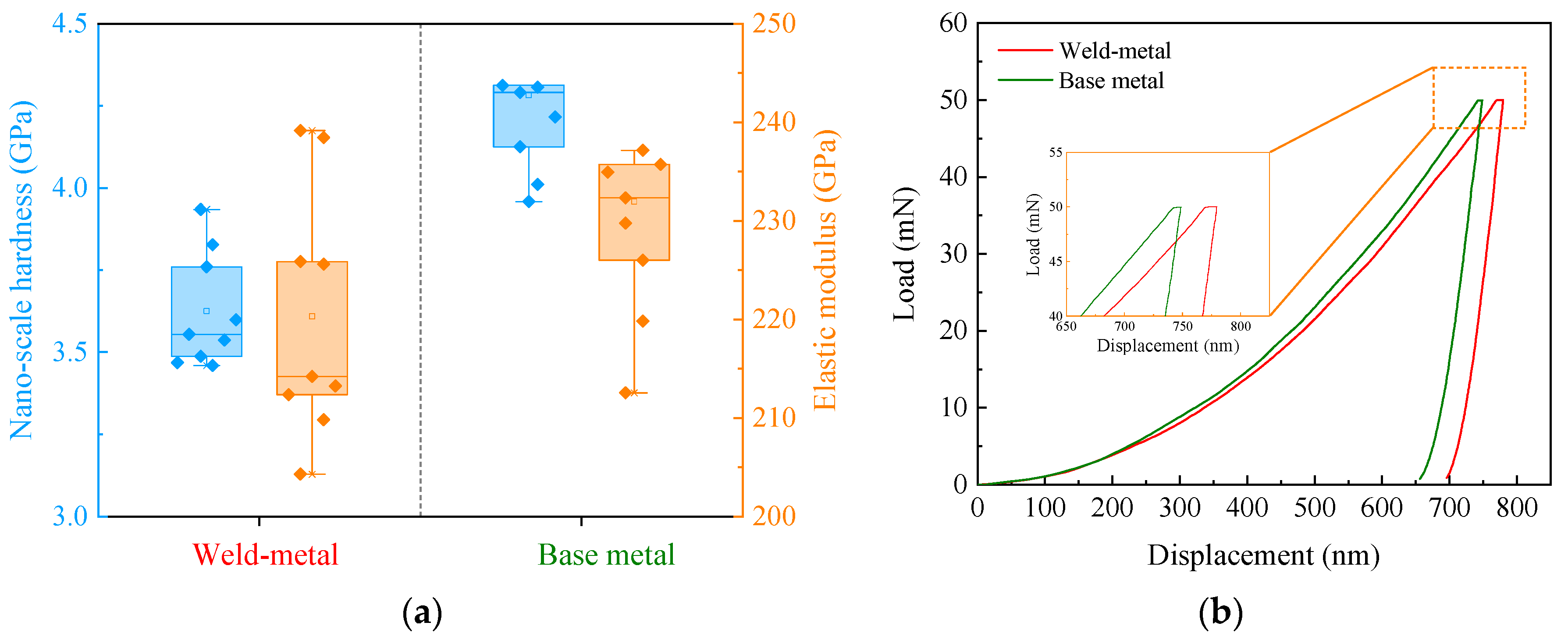
Figure 4 shows the nano−scale hardness, elastic modulus, and load−displacement curves of the weld and base metals. The nano−scale hardness value of the weld metal is significantly lower than that of the base metal, and the elastic modulus of the weld metal is slightly lower (Figure 4a), while the indentation deformation of the weld metal is slightly higher (Figure 4b). This is mainly the recrystallization during the welding process leading to a significant change in the proportion of deformed grains, sub−structure grains, and recrystallized grains [22,23]. It is worth noting that the hardness of ferrite is lower than that of pearlite, whereas the toughness is better. Simultaneously, the proportion of ferrite in weld metal is significantly higher (Figure 3b), while the base metal is mostly composed of lamellar pearlite (Figure 3c,d). For the record, the high proportion of ferrite in weld metal, resulting in the deformation displacement of weld metal in the holding and unloading stage, is higher than that of the base metal (Figure 4b).
Figure 5 shows the stress–strain curves of the welded rail joint specimen and base metal specimen. The yield and tensile strength values of the all−weld−metal specimen are 385 MPa and 1090 Mpa, respectively, which is about 24.51% and 7.63% lower than that of the base metal specimen. In addition, the elongation of the all−weld−metal specimen is 57.1% higher than that of the base metal specimen. This is not surprising since the all−weld−metal specimen has a strong undermatching in the weld region, as clearly indicated by hardness measurements. Similar behavior has also been reported for the welded joints with a strong undermatching in the weld region, such as friction stir−, laser−, or electron−beam−welded Al−alloys [24,25,26,27,28,29,30,31,32]. Undoubtedly, the variation trend of stress–strain curves is closely related to the microstructure of the specimens. The ferrite number at welded rail joints increases significantly (Figure 3a), resulting in lower strength but better plasticity (Figure 4). In other words, the yield and tensile strength of the all−weld−metal specimen is low, but the plasticity is relatively better.

3.2. Fracture Morphology

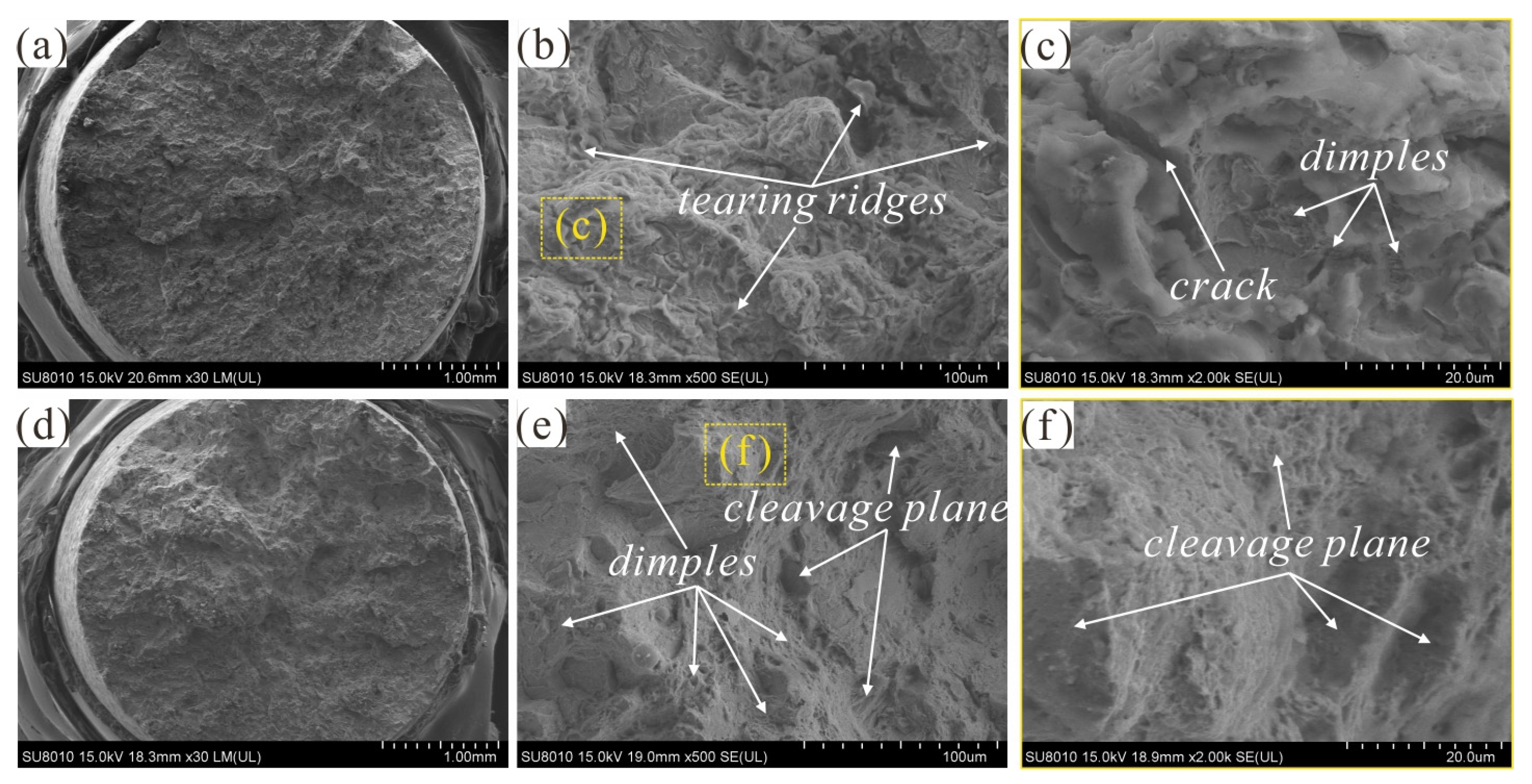
Figure 6 shows the tensile fracture morphology of all−weld−metal and base metal specimens. On the whole, the two specimens are divided into smooth and rough zones (Figure 6a,d), and the Figure 6c,f are the enlarged graph of the Figure 6b,c, respectively. Simultaneously, more dimples and tearing ridges can be detected on the fracture morphology of the all−weld−metal specimen (Figure 6b,c), while the fracture morphology of the base metal specimen is filled with shallow dimples and cleavage planes (Figure 6e,f). Obviously, the fracture mode of the all−weld−metal specimen is mainly plastic fractures, while the base metal specimen is a typical brittle fracture. This phenomenon is due to the low strength and good plasticity of the all−weld−metal specimen (Figure 4b), and the higher plasticity makes the material break later [33].

3.3. Coefficient of Friction

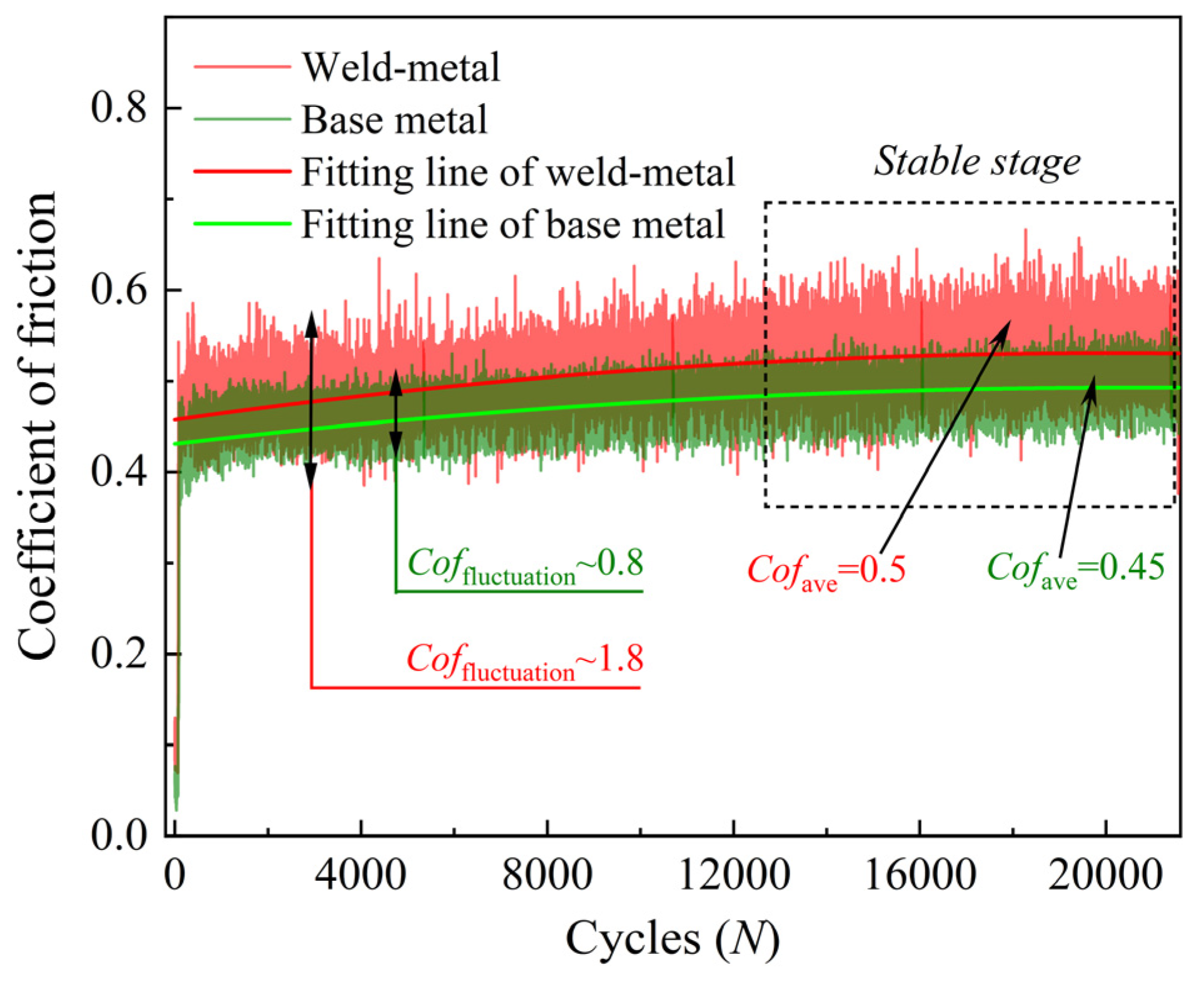
Figure 7 shows the COF (coefficient of friction) time−varying curves of the weld and base metal specimens during a reciprocating tribological test. In general, the COF shows a slow upward trend as the number of cycles increase, following which the coefficient of friction tends to be stable (the number of cycles increased to 15,000). In the stable stage, the average COF of the weld and base metal specimens are 0.5 and 0.45, respectively. Moreover, the weld joint has a relatively higher COF, and its fluctuation amplitude is 1.25 times higher than the base metal. It is mainly the hardness value of the base metal that is relatively high, and the wear mechanism does not change significantly during the cycle, resulting in a relatively more stable COF.

3.4. Surface Damage Morphology

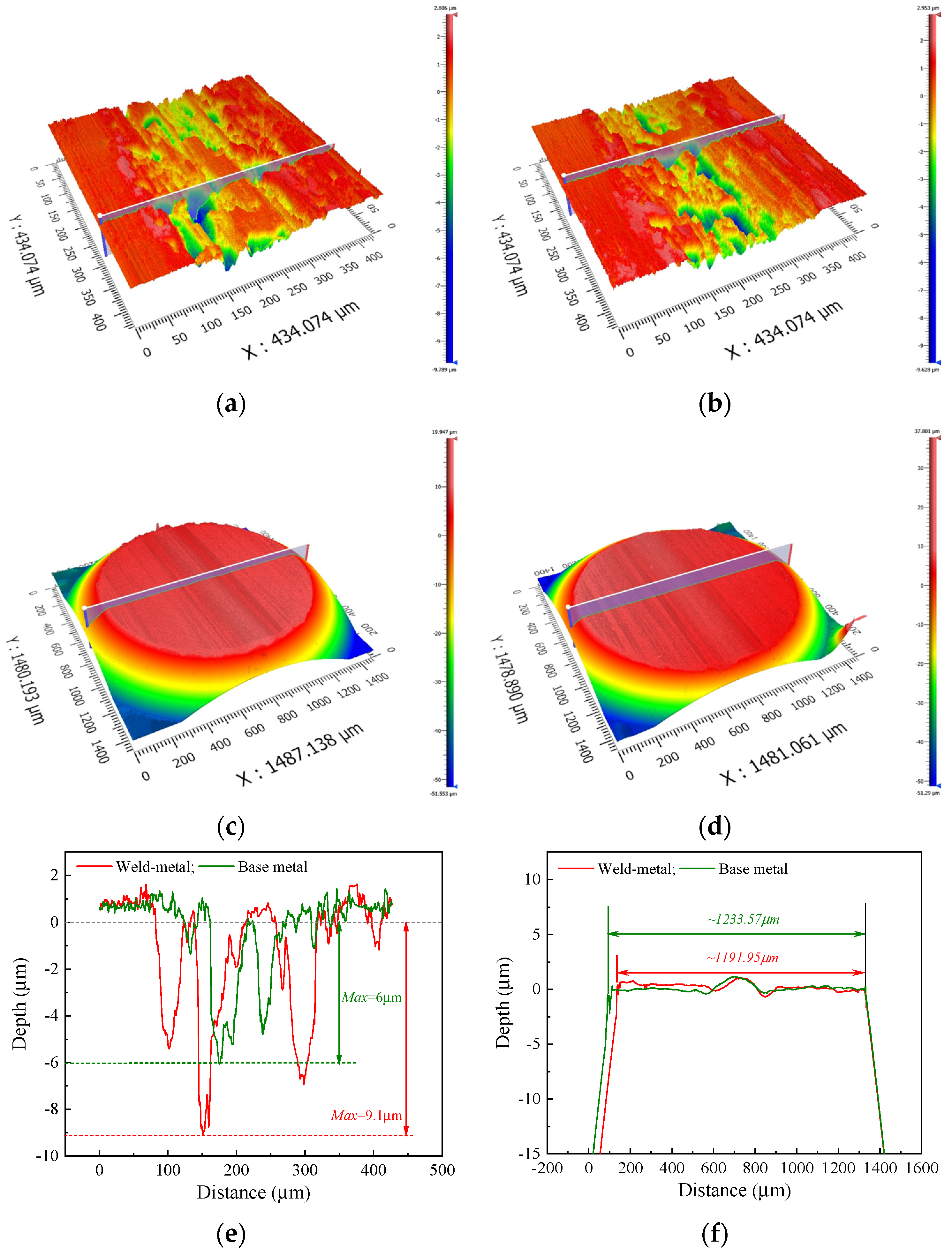
Figure 8 shows three−dimensional surface topographies of a weld metal, base metal, and GCr15 steel ball (tribological pair specimens). The obvious ploughing and peeling pit can be observed on the worn surface, and the ploughing is deeper than that of the base metal (Figure 8a,b,e). A two−dimensional, cross−sectional profile comparison shows that the weld metal’s maximum wear depth is 9.1 μm, while the base metal’s is 6 μm (Figure 8e). Moreover, ploughing can be observed on the worn surface of the GCr15 steel ball (Figure 8c,d), and the cross−section width of the weld metal pair is relatively small (Figure 8f). The hardness value of the weld metal is relatively lower, resulting in a decrease in the material removal effect of the tribological pair steel ball, and the wear width of the tribological pair steel ball is relatively narrower. For the record, the wear debris, as the third body medium at the friction interface, will aggravate the damage of the worn surface, resulting in ploughing appearing on the worn surface of the rail and the GCr15 steel ball [34,35].
In order to reveal the damage mechanism of the weld metal and base metal, the surface damage morphology is shown in Figure 9, and the Figure 9b,h are the enlarged graph of the Figure 6a,g, respectively. In Figure 9a,b, the worn surface of the weld metal is uneven; there are obvious cracks and serious delamination characteristics, and the ploughing is narrow and deep. The worn surface of the base metal is relatively flat, and no obvious peeling pits are observed, but there are obvious friction films and many adhesions (Figure 9g,h). Moreover, there is no obvious difference in the content of iron and carbon between the weld and base metals (Figure 9d,e,j,k), while the oxygen content in the base metal is higher than that in the weld metal (Figure 9f,i and Figure 10). In addition, the damage to the weld metal is mainly fatigue wear, while the base metal is adhesive wear. Due to the hardness value of the weld metal being relatively lower, the external force causes plastic deformation of the material, and microcracks form after plastic depletion. Thus, the continuous penetration of microcracks leads to delamination characteristics of the worn surface [36]. On the contrary, the hardness value of the base metal is relatively higher and the friction film phenomenon occurs at the initial friction stage due to the increase in temperature, which results in the friction film of the base metal protecting the worn surface and the relatively flat surface is more conducive to the adhesion of the oxide film. However, as the friction continues, the friction film is broken and mixed with the wear debris to form the third medium in the friction interface, resulting in wide and shallow ploughing characteristics that will appear in the later stage of friction [34,35]. Subsequently, the surface damage of the weld metal is more serious than that of the base metal, and the wear resistance is worse.

4. Discussion

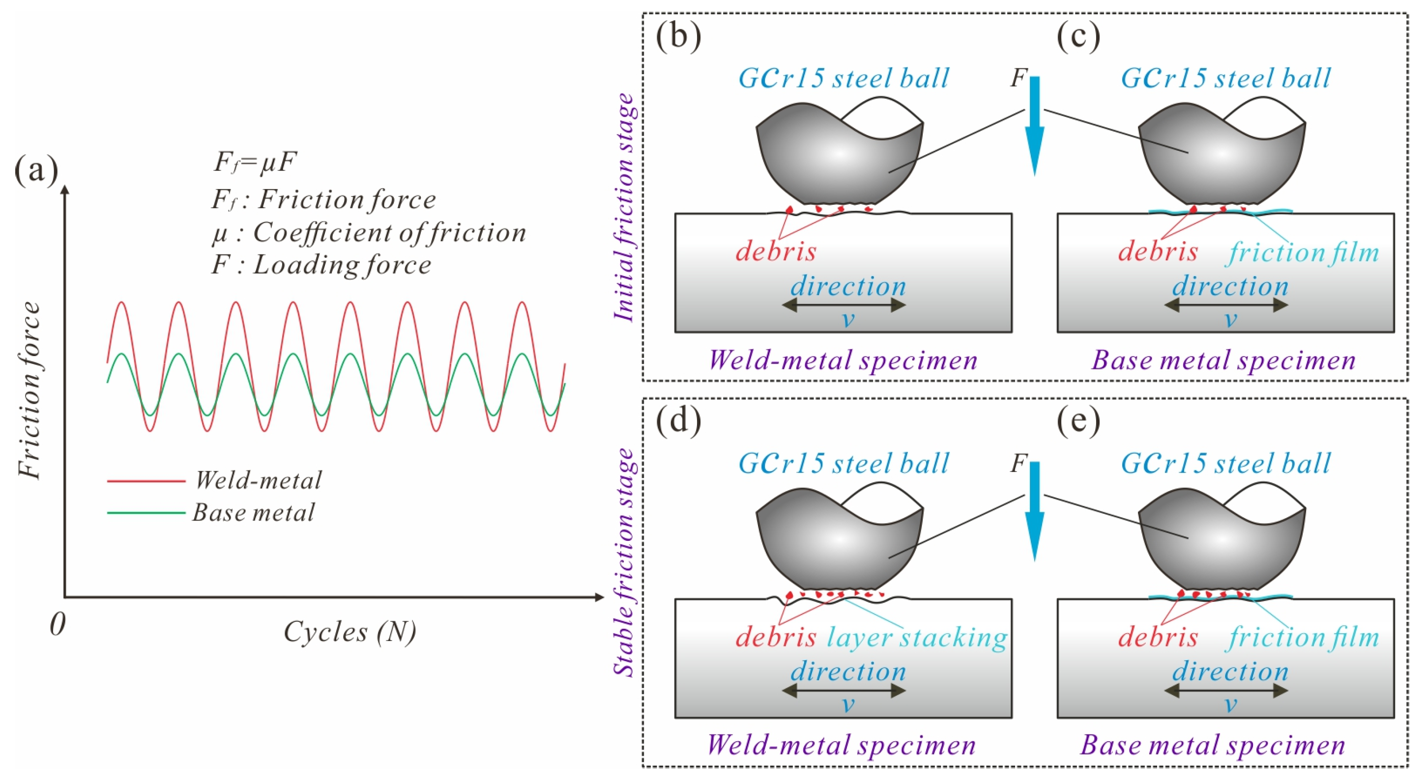
Generally, the damage of the weld metal and base metal is related to friction and contact states. Figure 11 displays the initial and stable friction stage. It is well known that the two specimens each contact other specimens which will produce deformation, and the contact spot area is mainly determined by the hardness of the rail material as the friction pair material tested is the GCr15 steel ball. The welding process causes the microstructure of materials to change (Figure 3), resulting in the hardness value of the weld metal being relatively lower (Figure 4a). Therefore, the deformation of the softer weld metal (Figure 4a) is relatively larger, but in the GCr15 steel ball it is relatively smaller, resulting in a smaller contact spot area and deeper wear (Figure 8e,f). At the initial friction stage, the weld metal specimen with better plasticity (Figure 4b and Figure 6) produces greater deformation, and the debris on the worn surface does not easily to fall off, resulting in the worn surface to be rougher (Figure 9a,b). Moreover, the lamellar debris of the weld metal induced by delamination wear is directly involved in friction, resulting in a higher average COF and friction force [37] (Figure 7 and Figure 11a,b). However, the yield and tensile strength values of the all−weld−metal specimen are 385 MPa and 1090 MPa, respectively, and the elongation of the all−weld−metal specimen is 57.1% higher than that of the base metal specimen (Figure 5). Thus, the base metal has poor plasticity and a higher hardness value and yield strength (Figure 4, Figure 5 and Figure 6), resulting in a relatively flat worn surface (Figure 9g,h).
As the same time, the friction film appears on the worn surface of the base metal due to the increase in temperature, and the friction film plays a protective role (Figure 11c), resulting in the COF and its fluctuation amplitude being relatively lower [38] (Figure 7). As the friction progresses, the friction film mixes with wear debris to form a third body medium which participates in the friction (Figure 11e). As shown in Figure 9, there is no obvious difference in the content of iron and carbon between the weld and base metals (Figure 9d,e,j,k), while the oxygen element of the obviously base metal increases (Figure 9f,l). This phenomenon shows that the weld and base metals will produce debris peeled from the material during the wear process, while the worn surface of the base metal occurs due to the obvious oxide film. It has been found that the debris at the friction interface is embedded in the dual surface and they interlock with each other, resulting in ploughing on the contact surface [39]. Thus, there are obvious ploughing characteristics on the worn surface of the GCr15 steel ball (Figure 8d). In the stable friction stage, the oxide film on the worn surface of the base metal is continuously generated and removed to achieve a dynamic balance, and the oxide film on the surface of the base metal reduces damage (Figure 9g,h and Figure 11e), leading to the COF and its fluctuation amplitude being relatively lower [38] (Figure 7). Obviously, the weld metal has better plasticity, but the hardness and yield strength values are lower than that of the base metal (as shown in the Figure 4 and Figure 5), and the friction force and fluctuation amplitude are relatively lager, resulting in more serious damage of the weld metal than the base metal (Figure 8 and Figure 9). In the tensile test, the more dimples and tearing ridges that can be detected on the fracture morphology of the all−weld−metal specimen (Figure 6b,c), the relatively larger deformation production of the weld metal during friction. Therefore, during the friction and wear process, the material deformation of the weld metal is relatively larger and obviously removed, and the worn surface appears with deeper ploughing and thicker accumulation layers (Figure 9a,b and Figure 11d). In short, the damage mechanism of the weld metal is mainly fatigue wear, and the base metal is mainly adhesive wear.

5. Conclusions

The tensile and tribological tests were conducted on the tension–torsion multi−axis electric servo fatigue testing machine and self−made multi−functional friction and wear testing machine, respectively. The fracture morphology and surface wear behavior of the weld metal and base metal rails were studied by their microstructure, hardness, yield and tensile strength, elongation, coefficient of friction, and element content on their worn surfaces. The following conclusions can be drawn:
(1)
The length of the weld metal is about 200μm and has a large amount of ferrite, while the base metal is lamellar pearlite and no obvious ferrite was observed, leading to a significantly higher nano−scale hardness value. Simultaneously, the high proportion of ferrite in the weld metal results in higher plasticity than that of the base metal.
(2)
The yielding and strength of the welded specimen are 385 MPa and 1090 MPa, respectively, which are about 24.51% and 7.63% lower than that of the base metal specimen. More dimples and tearing ridges can be detected on the fracture morphology of the all−weld−metal specimen, while the fracture morphology of the base metal specimen is filled with shallow dimples and cleavage planes.
(3)
The all−weld−metal specimen has a relatively higher COF, and its fluctuation amplitude is 1.25 times higher than that of the base metal specimen, which was due to the rougher worn surface. In the stable stage, the average COF of the all−weld−metal and base metal specimens are 0.5 and 0.45, respectively.
(4)
The introduction of flash−butt welding will change the wear mechanism of the U75VG rail from adhesive wear and oxidation to fatigue wear and slight oxidation, leading to slighter wear damage. Therefore, the worn surface of the weld metal is uneven; there are obvious cracks and serious delamination characteristics, and the ploughing is narrow and deep, while the worn surface of the base metal is relatively flat and no obvious peeling pits are observed, and there are obvious friction films and many adhesions.

Author Contributions

Conceptualization, M.S.; methodology, S.L. and J.P.; software, B.R.; validation, M.S. and S.L.; formal analysis, M.S. and Q.L.; investigation, M.S. and B.R.; resources, M.S.; data curation, B.R.; writing—original draft preparation, B.R.; writing—review and editing, M.S.; visualization, S.L.; supervision, M.S. and Q.L.; project administration, J.P.; funding acquisition, M.S. All authors have read and agreed to the published version of the manuscript.

Funding

This research was funded by the National Natural Science Foundation of Jiangxi Province (nos. 20212ACB214003 and 20224ACB204012), Technology Research and Development Project from the CHINA RAILWAY (no. N2021T012), National Natural Science Foundation of China (no. 52061012), and the Open Fund of Traction Power State Key Laboratory (TPL1906).

Data Availability Statement

No new data were created or analyzed in this study. Data sharing is not applicable to this article.

Acknowledgments

The authors thank Fengjun Gong from Jiangxi Ruichang Railway Construction Co. LTD for providing the technical support and samples of welded rail with welded joints.

Conflicts of Interest

The authors declare no conflict of interest. The funders had no role in the design of the study; in the collection, analyses, or interpretation of data; in the writing of the manuscript; or in the decision to publish the results.

References

  1. Farhangi, H.; Mousavizadeh, S.M. Horizontal split−web fractures of flash butt welded rails. In Proceedings of the 8th International Fracture Conference; Yildiz Technical University: Istanbul, Turkey, 2007. [Google Scholar]
  2. Porcaro, R.R.; Faria, G.L.; Godefroid, L.B.; Apolonio, G.R.; Candido, L.C.; Pinto, E.S. Microstructure and mechanical properties of a flash butt welded pearlitic rail. J. Mater. Process. Technol. 2019, 270, 20–27. [Google Scholar] [CrossRef]
  3. Shi, S.C.; Wang, W.C.; Ko, D.K. Influence of Inclusions on Mechanical Properties in Flash Butt Welding Joint of High−Strength Low−Alloy Steel. Metals 2022, 12, 242. [Google Scholar] [CrossRef]
  4. Skyttebol, A.; Josefson, B.L.; Ringsberg, J.W. Fatigue crack growth in a welded rail under the influence of residual stresses. Eng. Fract. Mech. 2005, 72, 271–285. [Google Scholar] [CrossRef]
  5. Stone, D.H.; Lwand, H.C.; Kristan, J.; Lehnhoff, G.R. Flash Butt Rail Weld Vertical Fractures. J. Fail. Anal. Prev. 2015, 15, 33–38. [Google Scholar] [CrossRef]
  6. Bauri, L.F.; Alves, L.H.D.; Pereira, H.B.; Tschiptschin, A.P.; Goldenstein, H. The role of welding parameters on the control of the microstructure and mechanical properties of rails welded using FBW. J. Mater. Res. Technol. 2020, 9, 8058–8073. [Google Scholar] [CrossRef]
  7. Kabo, E.; Ekberg, A.; Maglio, M. Rolling contact fatigue assessment of repair rail welds. Wear 2019, 436, 203030. [Google Scholar] [CrossRef]
  8. Zhao, X.H.; Fan, Y.J.; Liu, Y.; Wang, H.Y.; Dong, P. Evaluation of fatigue fracture mechanism in a flash butt welding joint of a U75V type steel for railroad applications. Eng. Fail. Anal. 2015, 55, 26–38. [Google Scholar] [CrossRef] [Green Version]
  9. Li, X.Y.; Ma, R.; Liu, X.; Lv, Q.B.; Wang, X.; Tian, Z. Effect of laser shock peening on fatigue properties of U75VG rail flash−butt welding joints. Opt. Laser Technol. 2022, 149, 107889. [Google Scholar] [CrossRef]
  10. Xu, J.M.; Wang, P.; Gao, Y.; Chen, J.Y.; Chen, R. Geometry evolution of rail weld irregularity and the effect on wheel−rail dynamic interaction in heavy haul railways. Eng. Fail. Anal. 2017, 81, 31–44. [Google Scholar] [CrossRef]
  11. Li, W.; Xiao, G.W.; Wen, Z.F.; Xiao, X.B.; Jin, X.S. Plastic deformation of curved rail at rail weld caused by train–track dynamic interaction. Wear 2011, 271, 311–318. [Google Scholar] [CrossRef]
  12. Fang, X.Y.; Zhang, H.N.; Ma, D.W.; Wu, Z.J.; Huang, W. Influence of welding residual stress on subsurface fatigue crack propagation of rail. Eng. Fract. Mech. 2022, 271, 108642. [Google Scholar] [CrossRef]
  13. Cai, W.; Wen, Z.F.; Jin, X.S.; Zhai, W.M. Dynamic stress analysis of rail joint with height difference defect using finite element method. Eng. Fail. Anal. 2007, 14, 1488–1499. [Google Scholar] [CrossRef]
  14. Zhao, J.Z.; Peng, X.; Fu, P.L.; Wang, Y.; Kang, G.Z.; Wang, P.; Kan, Q.H. Dynamic constitutive model of U75VG rail flash−butt welded joint and its application in wheel−rail transient rolling contact simulation. Eng. Fail. Anal. 2022, 134, 106078. [Google Scholar] [CrossRef]
  15. Sen, P.K.; Bhiwapurkar, M.; Harsha, S.P. A 3−D numerical simulation of fatigue crack growth in an alumino thermite welded UIC60 rail joint under different loading conditions. Mater. Today Proc. 2022, 59, 405–412. [Google Scholar] [CrossRef]
  16. Sen, P.K.; Bhiwapurkar, M.; Harsha, S.P. UIC60 rail alumino thermite weld’s semi elliptical head crack and stress intensity factor using ANSYS. Mater. Today Proc. 2022, 56, 3058–3064. [Google Scholar] [CrossRef]
  17. Pang, Y.; Grilli, N.; Su, H.; Liu, W.C.; Ma, J.; Yu, S.F. Experimental investigation on microstructures and mechanical properties of PG4 flash−butt rail welds. Eng. Fail. Anal. 2022, 141, 106650. [Google Scholar] [CrossRef]
  18. Zhang, H.; Zhang, S.Y.; Zhong, H.; Wang, W.J.; Meli, E.; Cui, X.L. Damage mechanism of a long−wavelength corrugated rail associated with rolling contact fatigue. Eng. Fail. Anal. 2022, 136, 106173. [Google Scholar] [CrossRef]
  19. Tawfik, D.; Mutton, P.J.; Chiu, W.K. Experimental and numerical investigations: Alleviating tensile residual stresses in flash−butt welds by localised rapid post−weld heat treatment. J. Mater. Process. Technol. 2008, 196, 279–291. [Google Scholar] [CrossRef]
  20. Ma, N.S.; Cai, Z.P.; Huang, H.; Deng, D.A.; Murakawa, H.; Pan, J.L. Investigation of welding residual stress in flash−butt joint of U71Mn rail steel by numerical simulation and experiment. Mater. Des. 2015, 88, 1296–1309. [Google Scholar] [CrossRef]
  21. Mansouri, H.; Monshi, A. Microstructure and residual stress variations in weld zone of flash−butt welded railroads. Sci. Technol. Weld. Join. 2004, 9, 237–245. [Google Scholar] [CrossRef]
  22. Su, Y.; Li, W.Y.; Wang, X.Y.; Ma, T.J.; Ma, L.; Dou, X.M. The sensitivity analysis of microstructure and mechanical properties to welding parameters for linear friction welded rail steel joints. Mater. Sci. Eng. A 2019, 764, 138251. [Google Scholar] [CrossRef]
  23. Su, H.; Li, J.; Lai, Q.; Pun, C.L.; Mutton, P.; Kan, Q.H.; Kang, G.Z.; Yan, W.Y. Ratcheting behaviour of flash butt welds in heat−treated hypereutectoid steel rails under uniaxial and biaxial cyclic loadings. Int. J. Mech. Sci. 2020, 176, 105539. [Google Scholar] [CrossRef]
  24. Çam, G.; Javaheri, V.; Heidarzadeh, A. Advances in FSW and FSSW of dissimilar Al−alloy plates. J. Adhes. Sci. Technol. 2022, 37, 162–194. [Google Scholar] [CrossRef]
  25. Çam, G. Prospects of producing aluminum parts by wire arc additive manufacturing (WAAM). Mater. Proc. 2022, 62, 77–85. [Google Scholar] [CrossRef]
  26. Luo, G.Y.; Cheng, M.P.; Liu, C.H.; Li, S.M.; Wang, X.G.; Song, L.J. Improving mechanical properties of quasi−continuous−wave laser beam welded 7075 aluminum alloy through microstructural refinement and homogenization of the fusion zone. Opt. Laser Technol. 2022, 153, 108221. [Google Scholar] [CrossRef]
  27. Liu, F.C.; Zhou, B.S.; Mao, Y.Q.; Huang, C.P.; Chen, Y.H.; Wang, Z.T. Microstructure and mechanical properties of laser welded joints between 2198/2060 Al–Li alloys. Mater. Sci. Technol. 2018, 34, 111–122. [Google Scholar] [CrossRef]
  28. Zhou, X.H.; Zhao, H.Y.; Liu, F.Y.; Yang, B.A.; Xu, B.X.; Chen, B.; Tan, C.W. Effects of beam oscillation modes on microstructure and mechanical properties of laser welded 2060 Al−Li alloy joints. Opt. Laser Technol. 2021, 144, 107389. [Google Scholar] [CrossRef]
  29. Ipekoğlu, G.; Çam, G. Formation of weld defects in cold metal transfer arc welded 7075−T6 plates and its effect on joint performance. IOP Conf. Ser. Mater. Sci. Eng. 2019, 629, 012007. [Google Scholar] [CrossRef]
  30. Çam, G.; Ventzke, V.; Dos Santos, J.F.; Koçak, M.; Jennequin, G.; Gonthier−Maurin, P. Characterisation of electron beam welded aluminium alloys. Mater. Sci. Technol. 1999, 4, 317–323. [Google Scholar] [CrossRef]
  31. Ancona, A.; Lugara, P.M.; Sorgente, D.; Tricarico, L. Mechanical characterization of CO2 laser beam butt welds of AA5083. J. Mater. Process. Technol. 2007, 191, 381–384. [Google Scholar] [CrossRef]
  32. EI−Batahgy, A.; Kutsuna, M. Laser Beam Welding of AA5052, AA5083, and AA6061 Aluminum Alloys. Adv. Mater. Sci. Eng. 2009, 2009, 974182. [Google Scholar] [CrossRef] [Green Version]
  33. Yang, Z.J.; Li, J.X.; Hou, S.S.; Cao, J.H.; Wang, G.L.; Lang, S.T.; Ding, P. Microstructural characteristics and mechanical properties of Ti–6Al–2Nb–2Zr–0.4B alloy welded joint using tungsten inert gas welding. J. Mater. Res. Technol. 2022, 21, 3129–3139. [Google Scholar] [CrossRef]
  34. Lewis, R.; Dwyer−Joyce, R.; Lewis, S.R.; Hardwick, C. Tribology of the Wheel−Rail Contact: The Effect of Third Body Materials. Int. J. Railw. Technol. 2012, 1, 167–194. [Google Scholar] [CrossRef]
  35. Chen, J.F.; Chu, J.Y.; Jiang, W.C.; Yao, B.; Zhou, F.; Wang, Z.B.; Zhao, P.C. Experimental and Numerical Simulation to Study the Reduction of Welding Residual Stress by Ultrasonic Impact Treatment. Materials 2020, 13, 837. [Google Scholar] [CrossRef] [PubMed] [Green Version]
  36. Hardwick, C.; Lewis, R.; Stock, R. The effects of friction management materials on rail with pre existing rcf surface damage. Wear 2017, 384, 50–60. [Google Scholar] [CrossRef]
  37. Li, X.; Dong, M.; Jiang, D.Y.; Li, S.F.; Shang, Y. The effect of surface roughness on normal restitution coefficient, adhesion force and friction coefficient of the particle−wall collision. Powder Technol. 2020, 362, 17–25. [Google Scholar] [CrossRef]
  38. Xiao, Y.L.; Cheng, Y.; Zhou, H.B.; Liang, W.H.; Shen, M.X.; Yao, P.P.; Zhao, H.P.; Xiong, G.Y. Evolution of contact surface characteristics and tribological properties of a copper−based sintered material during high−energy braking. Wear 2021, 488–489, 204163. [Google Scholar] [CrossRef]
  39. McColl, I.R.; Ding, J.; Leen, S.B. Finite element simulation and experimental validation of fretting wear. Wear 2004, 256, 1114–1127. [Google Scholar] [CrossRef]
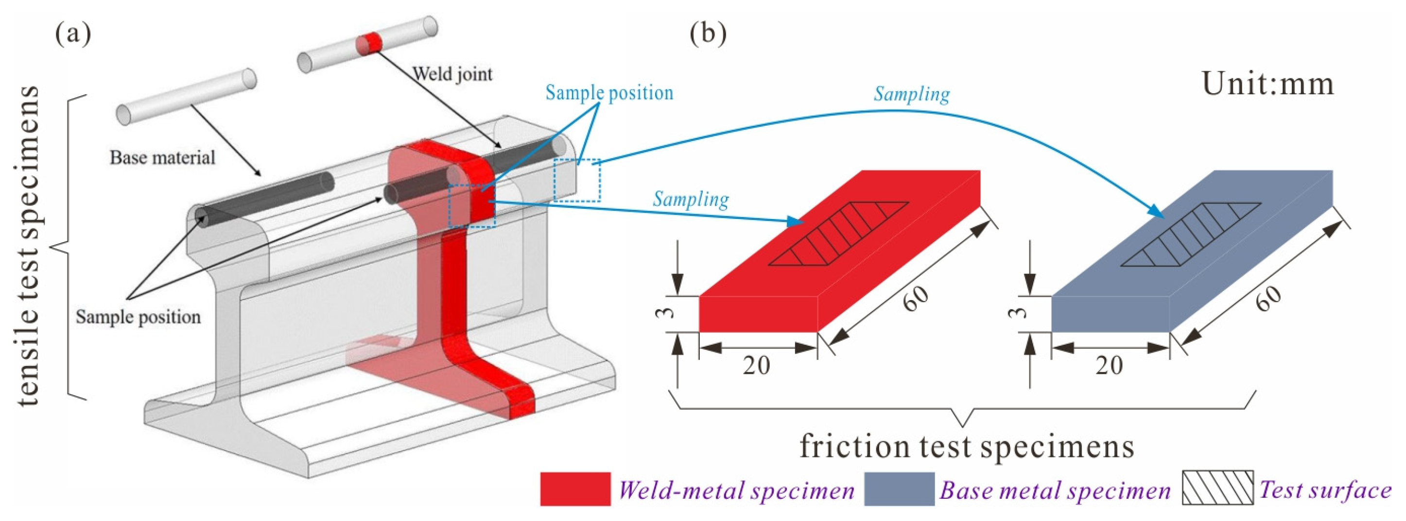
Figure 1. Sample position with (a) tensile specimens and (b) tribological specimens.
Lubricants 11 00041 g001
Figure 2. (a) Structure diagram of reciprocating friction and wear test bench, dimensions, and contact configuration of rail and GCr15 steel ball specimens, (b) size of tensile test specimens.
Lubricants 11 00041 g002
Figure 3. Microstructure of U75VG rail of (a) welded joint, and (b) weld metal, (c,d) base metal.
Lubricants 11 00041 g003
Figure 4. Mechanical characteristic of U75VG rail of (a) nano−scale hardness and elastic modulus, and (b) load−displacement curves.
Lubricants 11 00041 g004
Figure 5. The stress–strain response curves with all−weld−metal and base metal specimens.
Lubricants 11 00041 g005
Figure 6. Fracture morphology of the tensile specimens of (ac) all−weld−metal, and (df) base metal specimens.
Lubricants 11 00041 g006
Figure 7. Time−varying curves of coefficient of friction with weld and base metal specimens.
Lubricants 11 00041 g007
Figure 8. Three−dimensional topographies of the worn surface of (a,c) weld metal specimen and GCr15 steel ball, (b,d) base metal and GCr15 steel ball, cross−section profiles of worn surface of (e) rail and (f) GCr15 steel ball.
Lubricants 11 00041 g008
Figure 9. SEM and EDS map of the worn surface of (af) weld metal, (gl) base metal specimens.
Lubricants 11 00041 g009
Figure 10. Element content on worn surfaces of weld and base metal specimens.
Lubricants 11 00041 g010
Figure 11. Schematic diagram of (a) friction force and damage mechanism of (b), (c) initial friction stage and (d,e) stable friction stage.
Lubricants 11 00041 g011
Table 1. Welding process parameters.
upset force/KN35
upset length/mm10.5
welding time/s85–95
burning speed (mm/s)13.5–15.5
clamping length/mm130–150
weld width/mm20–25
input heat/MJ8.6
Table 2. Chemical composition of U75VG rail (wt.%).
CSiMnSPV
0.71~0.80.5~0.80.7~1.05≤0.03≤0.030.04~0.12
Table 3. Chemical composition of GCr15 steel ball (wt.%).
CSiMnCrMoS/PNi + Cu
0.95~1.050.15~0.350.25~0.451.45~1.65≤0.1≤0.025≤0.5
Disclaimer/Publisher’s Note: The statements, opinions and data contained in all publications are solely those of the individual author(s) and contributor(s) and not of MDPI and/or the editor(s). MDPI and/or the editor(s) disclaim responsibility for any injury to people or property resulting from any ideas, methods, instructions or products referred to in the content.