Abstract
The effect of variable DC bearing current amplitude, bearing current polarity, mechanical force, rotation speed, bearing temperature, and number of the balls on the fluting in an axial ball bearing type 51208 is investigated under DC currents. The results are obtained from two different test setups with two different lubricants (mineral-oil-based grease and polyglycol oil). The speed varies between 100 rpm and 2000 rpm, the axial bearing force between 200 N and 2400 N, the DC current amplitude between 0.5 A and 20 A, the bearing temperature between 29 °C and 80 °C, the number of steel balls per bearing between 3 and 15, and the test duration between 6 h and 168 h. The results show that with a higher bearing current density and/or a higher bearing speed, a lower bearing force and/or a lower bearing temperature, a bigger number of roller elements, but also at a negative polarity of a DC electric bearing current, the occurring of fluting is more probable and occurs at an earlier stage of operation.
1. Introduction
The e-mobility development with its inverter-fed electrical motors as main drives in cars combines fast-switching power electronic devices with mechanical components of the electrical motor such as the motor windings and bearings. Not only the necessary electrical currents for the motor torque generation, but also parasitic high-frequency (HF) currents flow in the motor drive systems, which may also flow through the mechanical motor bearings [1,2]. If the parasitic bearing current is small, the bearing raceway changes to a grey frosting appearance, which still allows for a safe bearing operation [3]. At increased bearing current amplitudes, the lubricant is aging strongly, e.g., it is blackening due to the release of carbon, and may even de-oil, leading to dry running and the failing of bearings. In many cases, a peak-and-valley fluting pattern of the bearing raceways also occurs in parallel, which excites increased bearing vibrations, which reduce the lubrication and lead to acoustic noise and in the end to bearing failure [2,4]. Recent research focuses on the cause-and-effect chain of parasitic currents in the drive train [5], on the determination of parasitic electrical capacitances in the electrical motor and the bearings at different lubrication stages such as mixed or full lubrication [6,7], on the electrical properties of the lubricant in terms of withstanding electrical current flow and on its electrical breakdown [8,9,10], and on the determination of changes in the bearing under electrical HF current flow [11,12]. The details of the initiation and of the cause-and-effect chain of the fluting pattern generation [13] is still not fully understood or reproduced by simulation today. Hence, in this paper, the impact of different operating parameters such as bearing current density, bearing speed and force, bearing temperature, and the type of lubricant on the generation of fluting is investigated experimentally to get a closer insight into the driving mechanism behind the fluting generation.
2. Parasitic Currents in Bearings of Inverter-Fed Electrical Machines
Electric currents in the bearings of inverter-fed electrical AC machines are mainly caused by the common-mode (CM) voltage (1) of the feeding power electronic inverters. The bearing currents are generated due to the high du/dt-changes of the CM voltage at the motor terminals in connection with the parasitic motor capacitances. This big du/dt-effect of the pulse-width-modulated (PWM) voltage source inverter output voltage is caused by the fast switching of the Si-based IGBTs (insulated gate bipolar transistor) or the SiC-based MOSFETs (metal-oxide-semiconductor field-effect transistor). Its effect on a parasitic current flow increases with increasing switching frequency, increasing the DC link voltage (DC: direct current) and the voltage change rate du/dt. Basically, electric motors are composed of conductive parts, i.e., iron and steel parts and copper windings, which are insulated from each other by non-conductive parts, i.e., insulators and air. Therefore, a system of parasitic capacitors exists between the conductive parts with in-between dielectric material components as non-conductive parts. In Figure 1a, the parasitic capacitors Csw-f, Csw-r, and Cr-f (see nomenclature) and the HF impedances ZPE, Zrg, Zb,NDE, and Zb,DE constitute an equivalent electrical circuit for the electrical machine at high du/dt. This equivalent circuit is a voltage divider at Zb = 1/(2πf·Cb), (Cb: bearing capacitance), causing an HF bearing voltage , originating from the common-mode terminal voltage :
which is the arithmetic average value of the three phase-to-ground terminal voltages uU-g, uV-g, and uW-g of the three phase terminals U, V, and W. This common-mode voltage can be measured between the stator winding star point in a three-phase stator star winding connection, or via an artificial star point in case of a stator delta winding connection, and the grounded stator housing (subscript g).
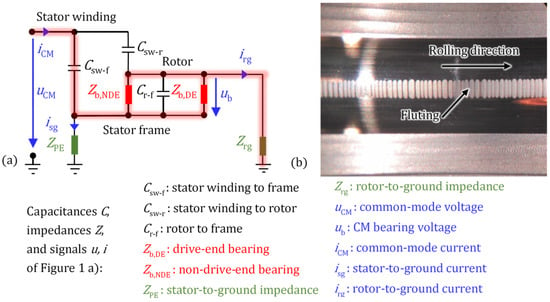
Figure 1.
(a) Electric common-mode equivalent circuit of an induction motor with parasitic capacitances, (b) measured fluting on the outer ring bearing raceway.
The HF grounding impedances of the stator iron ZPE and of the rotor iron Zrg, connecting stator and rotor to the ground, depend on the grounding condition of the electrical machine. If the stator frame has an electrically weak connection to the ground, and hence, a high impedance ZPE (Figure 1a), and the rotor has an electrically strong connection to the ground, e.g., via its coupling to a grounded load, and hence, low impedance Zrg, then a big CM rotor-to-ground current irg passes via the bearings to the ground. The capacitance Csw-f is typically by a factor that is bigger than Csw-r. So, at high frequencies f of the parasitic current, the impedance between the stator winding and the stator iron, which is roughly 1/(2πf·Csw-f), is much smaller than the impedance between the winding and the rotor iron, which is roughly 1/(2πf·Csw-r). Hence the rotor-to-ground current irg flows mainly along the high-lighted paths in Figure 1a, passing the bearings. If irg is sufficiently big, it may result in bearing raceway damage, either grey frosting or, worse, fluting like in Figure 1b, which occurred after a test duration tT = 1015 h due to a rotor-to-ground bearing current with an apparent bearing current density Jb = 0.52 A/mm2. The test was performed with a four-pole 1.5 kW cage induction motor, driven via a PWM IGBT two-level voltage source inverter (DC link voltage 560 V, switching frequency 10 kHz) at n = 1000 rpm with a mineral-oil-based lubricant (Arcanol Multi 3). Radial ball bearings of type 6205 C3 were used with an axial bearing force Fa = 50 N, a radial bearing force Fr = 63 N, and an average bearing temperature ϑb = 50 °C.
To compare the electrical loading of different bearings with different load capacities C concerning a critical time-averaged electric bearing current Ib, the “apparent” bearing current density Jb = Ib/AHz must be used with the calculated value of the total Hertz’ian area AHz per bearing raceway [14]. This total Hertz’ian area AHz is the sum of the Hertz’ian contact areas for all mechanically loaded ball–raceway contacts at the inner or at the outer bearing ring. It is calculated via [15,16,17], using the measured bearing force Fb.
The local electrically active contact points (called a-spots), with a typical diameter in the μm range [18,19] and where the momentary bearing current ib flows, have a much smaller area A, yielding a very high local current density ib/A and a related high local power loss density. These high local power densities cause high local temperature rises, which may lead to local surface melting, leaving craters at the contact points [20]. If the craters and their rims are small enough to be flattened by the by-passing roller elements, a mechanically stable grey frosting of the bearing raceway occurs. At bigger bearing current amplitudes with more pronounced crater rims, a transversal vibration of the by-passing roller elements is excited, which leads to the fluting of the raceway, e.g., as seen in Figure 1b. The details of the mechanism of the fluting pattern generation have until now not been reproduced by simulation, but it is an interaction of vibration masses, separated at least partially by a lubricant, and subjected to a considerable current flow. Using AHz instead of A leads to a much lower current density, therefore called “apparent” bearing current density Jb, which is used for the practical assessment of the electrical load of the bearing. If this apparent bearing current density Jb exceeds ca. 0.1 to 0.3 A/mm2, the bearings in the electrical machines may suffer from the electrical current flow [14], disturbing the bearing operation gradually by damaging the bearing surface as fluting and, later on, by strongly degrading the lubricant material [9,21]. With fluting, the bearing vibrates and gets noisy. It suffers from increased friction losses, which eventually leads to bearing failure, e.g., by mechanical structural breaking of the cage [10].
The bearing current flow is bottlenecked through the above-noted tiny contact a-spots to pass the metallic surface between the ball and the raceway. Since the radius of a typical a-spot is very small (in the order of 1 μm) [19], the contact shows a much bigger so-called constriction resistance, compared with an imaginary case, where the entire mechanically touching surface conducts the current. The resistance of the bulk metal body of the bearing is negligible in comparison to the constriction resistance. The constriction resistance represents the dominant part of the bearing’s electrical resistance [22].
Considering Zb in Figure 1a, a ball bearing is modelled as a capacitor Cb when at elevated full speeds, i.e., hydrodynamic lubrication occurs, where the thickness of the highly resistive lubricant film h between the raceway and the balls is big enough to separate the balls and the raceway, also electrically, from each other. Then, only capacitive bearing currents ib ≈ Cb·dub/dt will flow through the bearing. In this case, the capacitors Cb,NDE and Cb,DE substitute the time-varying non-linear bearing impedances Zb,NDE and Zb,DE, respectively (NDE: non-drive-end, DE: drive-end).
When a bearing voltage ub is applied to the bearing at full lubrication, and the resulting electric field strength Eb = ub/h in the lubrication film exceeds the breakdown electric field of the lubricant of typically ED ≈ 30 V/μm (at virgin lubricant condition), a lubricant dielectric breakdown occurs via avalanche ionization of the lubricant molecules [23], allowing a bearing current flow ib between the ball and the raceway through the ionized, and therefore now conductive, lubricant [23]. The high local discharge current density melts the bearing surface at the electric contact points in the same way as explained above for the rotor-to-ground current [24]. Through a similar mechanism as noted above, the uneven surface with crater rims reduces the lubrication film thickness for the current path at the next bearing revolutions, or even penetrates the lubrication film and the surface oxide film, connecting ball and raceway directly [13,18,19,22]. So, as above, the bearing no longer behaves capacitively. This reveals a non-linear voltage–current characteristic (), which will be discussed in Section 3.
The bearing enters the mixed lubrication state when the thickness of the lubrication film h decreases, either due to a decreasing speed n typically lower than 500 rpm, or at an increased bearing temperature ϑb due to the reduced lubricant viscosity, or at an increased bearing force Fb or at an increasing surface roughness Sq. Hence, the electrical contact behaviour is similar to the situation after repeated lubricant film breakdown, as described above, leading again to a non-linear electrical () characteristic. In the mixed lubrication state, there are mechanical contacts between the balls and the raceway, regardless of the amplitude of the bearing current [16]. With further decreasing speed, the boundary lubrication state is reached, with increased mechanical contact areas between the roller elements and the raceway.
In conclusion, impressed HF rotor-to-ground currents and HF bearing discharge currents (electrical discharge machining currents, EDM) both may have a damaging impact on the bearing. This damaging effect appears after a relatively long time, typically after several hundred hours of operation. The generation of fluting with these HF bearing currents for a parameter study therefore takes too long. On the other hand, a damaging effect of DC bearing currents appears after a relatively short time, typically from some hours to some days, due to the continuous current flow. Unlike DC currents, the HF bearing currents are discontinuous. The sum of all current conduction durations for each impulse of the HF bearing currents in relation to the total operation time is much longer for the rotor-to-ground currents than for the discharge currents. But even for those, it is typically smaller by a factor 0.001 in comparison to DC bearing currents. Hence, a DC bearing current is much more intense than a HF bearing current at the same Jb in terms of the local electric energy delivered to the bearing by the current flow. Therefore, in the following, the tests are performed at DC currents to achieve short test times for fluting generation.
3. Axial Ball Bearing Test Rigs
3.1. Test Rig #1
To investigate the influence of electrical and mechanical parameters on the fluting, test rig #1 with two axial ball bearings was built (Figure 2a). With test rig #1, the bearing force Fb, the bearing speed n, and the momentary bearing current ib can be set. For transferring the electrical current from the rotating parts to the stationary parts without using mechanical brushes, two bearings are used in series (Figure 2b). Hence, no extra contact resistance of, e.g., a contacting sliding silver brush is added to the path of electric measurements.
The DC-feeding electric circuit is connected to the bearings via copper wires, which are soldered on ring 1 and ring 4 of the two tested axial bearings (Figure 2b). This bearing setup is connected to a DC source voltage . The bearing voltage , and thus the bearing current ib, are adjusted by the variable ohmic resistance Rvar. The bearing voltage is measured directly via copper wires, soldered close to the bearings. The resistivity of the bearing steel and of the aluminium in the rotating part is very small. So, the bulk resistance of the conductive materials in the electrical path has a negligible voltage drop compared with the voltage drop at the bearing contacts. As a result, the voltage drops at the stationary contact, i.e., between ring 3 and the rotating aluminium part, and between the rotating aluminium part and ring 2, are negligible compared with the voltage drop at the rolling contacts, i.e., between the balls and the raceways. A screw and a nut adjust the bearing force on a spring ring, placed mechanically in series with the bearings, applying the bearing force up to a max. of 1600 N on both bearings, which is measured via a load cell. The rotating rings of the bearings are placed on the rotating part (Figure 2b), which is connected to the shaft of the driving DC motor via an electrically insulated coupling. Ring 4 is electrically insulated from the screw, so the applied current only passes through the bearings. All four rings are mechanically kept centred to the rotating axis, which is not depicted in Figure 2b for simplicity. The temperatures of ring 1 (ϑr1) and of ring 4 (ϑr4) are directly measured via thermocouples. We assumed for the temperature of ring 2 and ring 3, respectively, the same values: ϑr2 = ϑr1 and ϑr3 = ϑr4. So, the average temperatures of bearing 1 (ϑb1) and bearing 2 (ϑb2) are, respectively, ϑb1 = ϑr1 = ϑr2 and ϑb2 = ϑr3 = ϑr4.
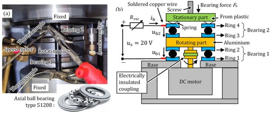
Figure 2.
Test rig #1 with the axial ball bearings. (a) Experimental setup, (b) setup structure. For equipment, see Table 1.

Table 1.
Lubricant and equipment for test rig #1.
In Figure 3, the measured non-linear voltage–current characteristic under DC conditions with grease lubricant Arcanol Multi 3 is given. The effects of the bearing rotational speed , of the bearing axial force , and of the time-averaged DC bearing current and apparent bearing current density in relation to the time-averaged bearing voltage are shown. The Hertz’ian areas AHz,400N = 1.0 mm2 and AHz,1600N = 2.5 mm2 are calculated values. The average bearing temperatures ϑb were adjusted via an external fan heater to remain between 31 °C and 35 °C. The bearing voltage and current are time-averaged over 2 s according to . The attribute “time-averaged” will be skipped in the following. In Figure 3, at low-speed n = 100 rpm, the bearing voltage for Fb = 400 N and 1600 N is ca. 0.61 V, which is almost equal to the bearing voltage = 0.63 V for current values Ib bigger than 0.5 A or 0.5 A/mm2 and 0.2 A/mm2, respectively. The rms surface roughness Rq of the new bearings was measured to be between 0.02 μm and 0.04 μm. From the Sq measurements of bearings with current passage (Section 4), values of 0.35 μm were typically found. So, for the short-term measurements with current passage in Figure 3, we assumed Rq1 = Rq2 = 0.08 μm for the raceway and ball, leading to a composite rms surface roughness σ = 0.11 μm for the calculation of the lubrication state in Table 2. At n = 100 rpm, the bearing is already in the boundary lubrication state. Hence, no complete lubrication film exists between the balls and raceway. At the higher speed n = 1500 rpm, the bearing voltage for the lower bearing force Fb = 400 N is bigger than for the higher bearing force Fb = 1600 N. At n = 1500 rpm, the bearing is in full lubrication. Hence, there is a lubrication film of several tenths of μm between the balls and raceway. With a bigger Fb, the lubrication film thickness h is smaller. So, only a lower bearing voltage is required for the electrical current flow. With a decreasing bearing current , the bearing voltage increases at the higher speed n = 1500 rpm and decreases at the lower speed n = 100 rpm before it reaches zero at = 0 A.
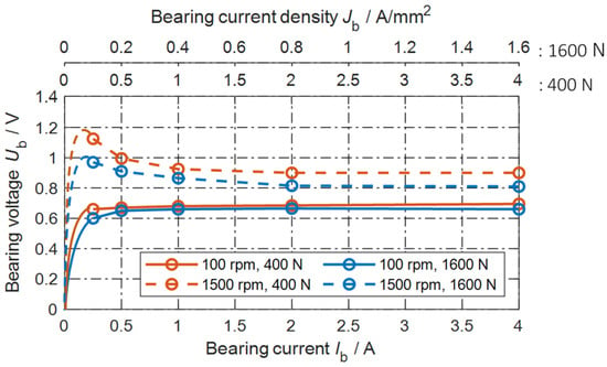
Figure 3.
Test rig #1: Measured bearing voltage per bearing versus measured DC bearing current , and versus apparent bearing current density , for two bearing speeds n = 100 rpm, 1500 rpm and two bearing forces Fb = 400 N, 1600 N.

Table 2.
Calculated lubrication film thickness h and lambda value λ for the tests in Figure 3 at ϑb = 33 °C, based on measured values of bearing force, speed, lubrication viscosity of the grease Arcanol Multi 3, and surface roughness values according to [15,16,17].
In Figure 3, with an increasing bearing current , the number of contact a-spots increases (A-fritting effect), and the existing contact spots enlarge (B-fritting effect) [19,22]. Hence, the contact resistance decreases, so that the bearing voltage at higher DC bearing currents and higher low-frequency AC bearing currents (e.g., f = 50 Hz) above > 1 A is nearly constant [20,25], ranging between roughly 0.5 V < < 1.5 V. With the DC voltage source = 20 V and the potentiometer Rvar in Figure 2b, a constant value for the momentary bearing current is set:
since << . In the measurements (Figure 4), the momentary bearing current ranges within 3.88 A < < 4.09 A, and is almost constant at ≈ 4 A. The fluctuations of the momentary bearing voltage around the average bearing voltage is due to the repeated “fritting” (electrical breakdown) of the surface oxide layer and of the boundary layers covering the bearing steel surface [22], as flows via many parallel contact points (a-spots) of a changing number.
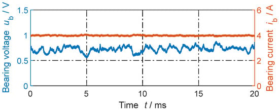
Figure 4.
Test rig #1: Measured DC bearing voltage per bearing (, see Figure 2b) and DC bearing current for n = 100 rpm, Fb = 400 N, and ϑb = 33 °C. Average bearing voltage . Grease lubricant Arcanol Multi 3.
In Figure 3, at DC bearing currents , the average electrical power delivered to the bearing is almost proportional to the bearing current , since the bearing voltage is almost constant, neglecting the small changes in between and .
3.2. Test Rig #2
Like test rig #1, test rig #2 in Figure 5 was built to investigate the electrical properties and fluting generation of the same type of an axial ball bearing type 51208. Unlike test rig #1, test rig #2 has mechanically smaller tolerances and operates with only one test bearing, which is drowned in polyglycol oil. The oil temperature is kept constant by a heater–cooler system by pumping a coolant liquid through the channels in the lower part of the test rig. The lubricant temperature is taken as the average bearing temperature ϑb. Test rig #2 can exert bearing forces up to Fb = 12 kN, bearing rotational speeds up to n = 3000 rpm, and uses a low-impedance silver graphite brush with a copper slip ring in the electrical path to measure . The slip ring is electrically connected to the upper bearing ring. Test rig #2 was originally designed for lubricant analysis (GESA) and is mounted in a four-ball apparatus (FBA). The lower bearing ring is mounted in the stationary housing, and the upper bearing ring is fixed on the rotating shaft, driven via a variable-speed induction motor. An axial force is applied to the test bearing by the lever arm of the FBA via the centre tip, which is electrically insulated by a plastic sleeve. A ceramic ball electrically insulates the drive shaft from the test shaft. The bearing voltage and the bearing current are recorded with the equipment, and are listed in Table 3. At DC operation, the rotating bearing ring has a positive electrical polarity, and the stationary ring has a negative polarity.
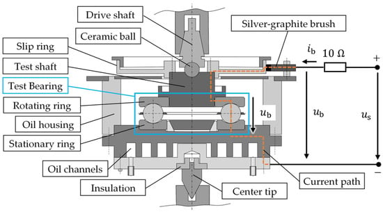
Figure 5.
GESA test rig #2 for an axial ball bearing, type 51208, under test, mounted on a four-ball apparatus (FBA), with the electrical circuit. The test bearing is drowned in polyglycol oil, where the oil temperature is controlled by an external heater–cooler system.

Table 3.
Lubricant and equipment for test rig #2.
4. Influencing Parameters on Fluting
In the following, the influence of the parameters DC bearing current amplitude Ib, DC current polarity, mechanical bearing force Fb, bearing speed n, average bearing temperature ϑb, and number of balls z was investigated on the generation of fluting. For each test, new bearings are used.
4.1. DC Bearing Current Amplitude
With test rig #1, four current amplitudes Ib = 0.5 A, 1 A, 4 A, and 20 A are investigated for n = 1500 rpm, Fb = 400 N, pc,max = 691 N/mm2, C/P = 110, and ϑb = 35 °C to 78 °C, using the grease lubricant Arcanol Multi 3, and z = 15.
The results in Figure 6 show that with an increasing bearing current, the probability of the occurrence of fluting increases. The fluting occurred first on the bearing rings with negative electrical polarity. With increasing Ib, for the same force Fb, Jb and hence the chance of fluting increases. For DC bearing current densities Jb < 1 A/mm2, even after 168 h no fluting is observed, which is a short-term test result. With long-term field operation [14,20] and long-term lab tests of up to 2 years duration [21], the limit for no fluting is typically Jb < 0.1 A/mm2, also for much lower DC currents. Operation with Jb > 2 A/mm2 resulted in fluting on the negative rings already after 24 h. Only at the very high Jb = 19.23 A/mm2 did the positive rings also exhibit a fluting pattern within 24 h. Note that for long-term field tests of several thousand hours with DC, low-frequency AC, or HF bearing currents, both raceways and the surface of the roller elements may show this fluting pattern [4,14,20].
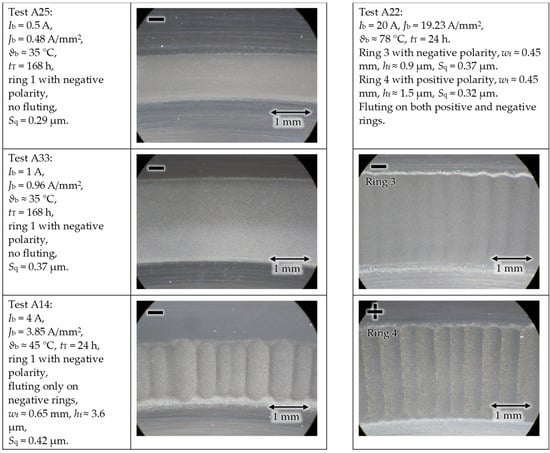
Figure 6.
Test rig #1: An increased DC bearing current amplitude and current density results in earlier and more pronounced fluting.
The fluting of the presented raceways was inspected after each test using a light microscope, and its surface profile was measured using a profilometer. The distance between the peaks of two consecutive and most significant fluting waves in Figure 7 wf and the distance between a peak and its adjacent valley hf was measured with the profilometer smartWLI. As an example, Figure 8 shows a scanned area of ca. 2 mm2 for test A14, where the local roughness signal was removed with a Gauss’ian S-filter for wavelengths shorter than 25 μm to allow for detection of fluting. In addition, the root mean square (rms) surface roughness Sq [15] in the measured 2 mm2 area of the raceway was determined. The curved raceway surface was approximated with the least square method by a polynomial of the third order and was removed from the roughness surface signal data via subtraction. The remaining signal data were filtered via an L-filter, based on ISO 25,178 [26]. The filter removes large-scale lateral components from the surface data, specifically with a Gauss’ian filter as defined in ISO 16610-61 [27], here, with a cut-off wavelength of 25 μm. So, a wavy surface with wavelengths larger than 25 μm is not considered. With this method, the local roughness due to craters of a-spots in the μm range is detected. These Sq values are given for the investigated examples with test rig #1 in Figure 6.

Figure 7.
Schematic side view of an exaggeratedly fluted raceway surface with the fluting width wf and fluting height hf for the visually most significant fluting section.

Figure 8.
(a) Measured scanned raceway surface of test A14 with the same location on ring 1 as shown in Figure 6.; (b) surface profile of white line in (a) with fluting width wf ≈ 0.65 mm and fluting height hf ≈ 3.6 μm.
With test rig #2, short-term tests of only 6 h with Ib = 1.5 A, 0.75 A, 0.375 A, and 0.1875 A with corresponding values Jb = 1.0 A/mm2, 0.5 A/mm2, 0.25 A/mm2, and 0.125 A/mm2 were performed for n = 2000 rpm, Fb = 700 N, pc,max = 832 N/mm2, and ϑb = 40 °C with polyglycol oil as lubricant and z = 15 balls.
The results in Figure 9 show that with Jb ≥ 0.5 A/mm2, fluting occurred on the stationary rings with negative polarities, whereas the positive rings showed no fluting after 6 h of operation time.
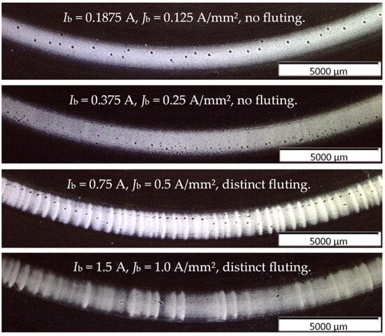
Figure 9.
Test rig #2: Increased DC bearing current amplitude and corresponding apparent bearing current density result in earlier fluting.
As noted above, the apparent bearing current density Jb = 0.1 A/mm2 is usually a safety limit to avoid fluting and used for designing the electric bearing current path. As long as Jb < 0.1 A/mm2, no fluting will be probable. If Jb > 0.1 A/mm2, fluting may happen and according to the presented results, the bigger Jb is, the bigger the chance of fluting is.
4.2. DC Bearing Current Polarity
With both test rigs #1 and #2, the polarity of the DC bearing current is changed for the same mechanical and electrical operating conditions. The test conditions for test rig #1 are n = 1500 rpm, Fb = 400 N, pc,max = 691 N/mm2, Ib = 4 A, Jb = 3.84 A/mm2, z = 15, grease lubricant Arcanol Multi 3, and tT = 24 h. The test conditions for test rig #2 are n = 2000 rpm, Fb = 2400 N, pc,max = 1255 N/mm2, Ib = 3.38 A, Jb = 1.0 A/mm2, z = 15, polyglycol oil as lubricant, and tT = 10 h.
The results in Figure 10 and Figure 11 show that fluting happens first on the rings with negative electrical polarity. The polarity was reversed with new bearings, again yielding fluting at the new rings with negative polarity. Due to the short test duration of 24 h with test rig #1 and 10 h with test rig #2, no fluting pattern occurred on the positive rings.
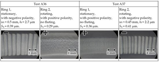
Figure 10.
Test rig #1 with reversed electrical DC current polarities in test A36 and test A37 with new bearings: fluting occurs first on the bearing rings with negative polarity.
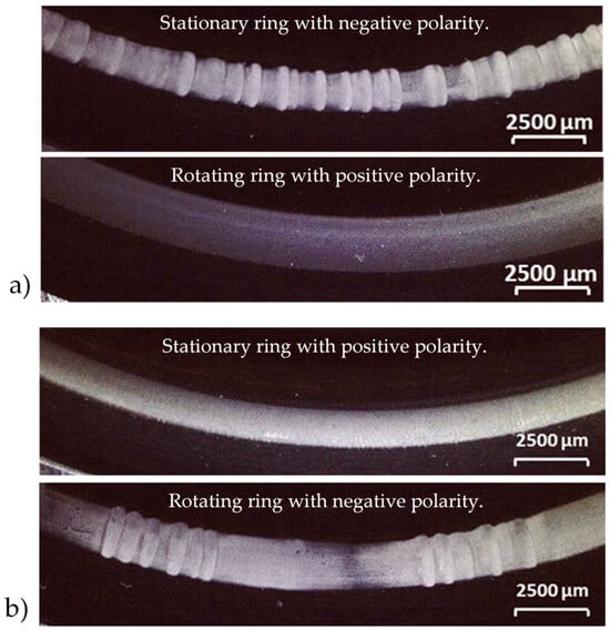
Figure 11.
Test rig #2 with reversed electrical DC current polarities in (a) and (b) with new bearings: fluting occurs first on the rings with negative polarity.
In [28], similar test results concerning the DC bearing current polarity have been reported. There, the mass of bearing wear was measured. The wear of the positive rings was bigger than that of the negative rings. It was concluded that the electric field polarity influences the surface oxidation thickness, causing the measured varying amounts of wear on the rings with different polarities. Perhaps this is also a clue to help explain why the negative rings show fluting first.
4.3. Mechanical Force
In test rig #1, only a bearing force up to Fb = 1600 N is possible, corresponding to C/P = 27.5, where P is the equivalent dynamic bearing load, here equal to the axial bearing force Fb, and C = 44 kN is the dynamic load capacity of the bearing. Next, four bearing force values Fb = 200 N, 400 N, 800 N, and 1600 N are investigated for n = 1500 rpm, Ib = 4 A, ϑb = 45 °C to 59 °C, grease lubricant Arcanol Multi 3, and z = 15.
The results in Figure 12 show that with a decreasing bearing force Fb, the chance of fluting increases. The rings with negative polarity are depicted, as the positive rings do not have any fluting after the given test durations tT. At the biggest bearing force Fb = 1.6 kN, even a doubling of the test duration from tT = 24 h to 48 h did not produce any fluting. With an increasing mechanical force Fb, the Hertz’ian area AHz increases. Hence, for the same bearing current amplitude Ib, the apparent bearing current density Jb = Ib/AHz decreases, and so, the chance of fluting decreases (see Section 4.1).
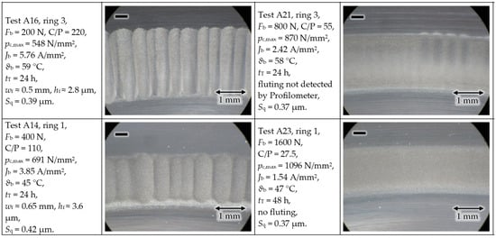
Figure 12.
Test rig #1: An increased bearing force gives less fluting at a constant bearing current.
4.4. Bearing Rotational Speed
According to hydrodynamics, with rising bearing rotational speed n, the lubrication film thickness h rises. Based on the theory of elasto-hydrodynamic lubrication (EHL), the minimum oil film thickness in the Hertz’ian area is directly proportional to the bearing speed ~ n0.68 and inversely proportional to the bearing force ~ Fb−0.073 [16]. The test conditions for test rig #1 are Fb = 400 N, pc,max = 691 N/mm2, Ib = 4 A, Jb = 3.85 A/mm2, z = 15, ϑb = 29 ° to 45 °C, tT = 24 h and 48 h, and grease lubricant Arcanol Multi 3, while for test rig #2, they are Fb = 2400 N, pc,max = 1255 N/mm2, Ib = 3.38 A, Jb =1.0 A/mm2, z = 15, polyglycol oil as lubricant, ϑb = 40 °C, and tT = 10 h.
The results in Figure 13 and Figure 14 show that with a decreasing speed n, the chance of fluting decreases. The raceways of the rings with negative polarity are depicted, as the positive rings did not have any fluting after the given short test durations tT. At standstill n = 0 rpm, no fluting occurs even for long test durations [18], as the same metallic contact area, without any lubrication film in between, is carrying the current. Although at tests A20 and A24, the same test time 48 h elapsed, at A24, the number of rollovers on a certain spot on the raceway is 1/5 times smaller due to the reduced speed. So, the electric erosion is 1/5 smaller, causing nearly no fluting at A24. Increasing the speed increases the lubrication film thickness, which according to Section 4.5 increases the chance of fluting, which is shown via the effect of a decreased bearing temperature ϑb in Figure 15.
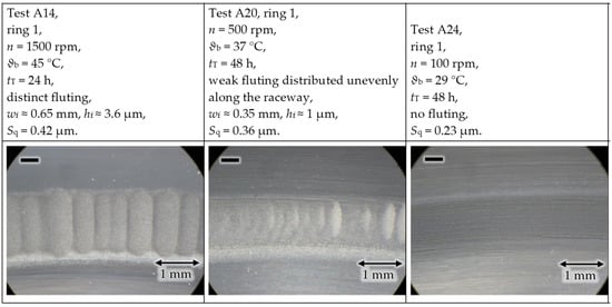
Figure 13.
Test rig #1: An increased rotational bearing speed leads to earlier fluting.
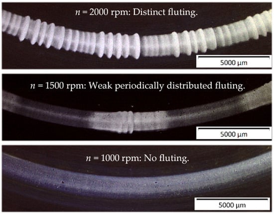
Figure 14.
Test rig #2: An increased rotational bearing speed leads to earlier fluting.
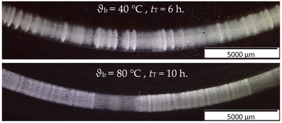
Figure 15.
Test rig #2: An increased bearing temperature gives less fluting.
The bearing speed influences not only the lubrication film thickness h, but also the ball’s lateral acceleration due to the increased surface roughness by the passing current, e.g., due to fluting. Assuming the lateral ball position , perpendicular to the raceway, to be sinusoidal according to the surface waviness
where is the amplitude of , is the wave count of raceway fluting, is the the bearing rotational speed, and is the time, then the perpendicular ball axial acceleration is given as
Hence, the ball with its mass is hammered ~ n2 to the surface with the perpendicular force (5), increasing the surface waviness with increasing speed n. This also supports the experimental results that with an increasing speed, fluting occurs earlier.
With test rig #2, three different speed values n = 2000 rpm, 1500 rpm, and 1000 rpm were investigated for Fb = 2400 N, Ib = 3.38 A, Jb = 1 A/mm2, ϑb = 40 °C, lubricant polyglycol oil, and z =15. The results in Figure 14 are similar to the results on test rig #1 in Figure 13. With a decreasing speed n, the chance of fluting decreases.
4.5. Average Bearing Temperature
With test rig #2, two different bearing temperatures ϑb = 40 °C and ϑb = 80 °C were investigated for n = 2000 rpm, Fb = 700 N, pc,max = 832 N/mm2, Ib = 1.5 A, Jb = 1.0 A/mm2, lubricant polyglycol oil, and z = 15.
The results in Figure 15 show that with an increasing bearing temperature ϑb, the chance of fluting decreases. The stationary bearing rings with negative polarity are depicted, as positive rings did not exhibit any fluting after the given test durations. The lower viscosity of the lubricant at a higher temperature results in a thinner lubrication film thickness h, which is also the case at a lower speed (see Section 4.4). In both cases, there is less fluting.
4.6. Number of Balls per Bearing
With test rig #1, the number of balls per bearing in the cage was reduced from z = 15 to 3 by removing 12 balls from the cage, leaving the remaining 3 balls in a symmetrical position in the cage. By changing Ib and Fb (e.g., Fb = 60 N and 300 N), Jb = 4.66 A/mm2 is kept constant for the two different values of z at the speed n = 1500 rpm with the grease lubricant Arcanol Multi 3.
The results in Figure 16 show that with an increasing number of balls per bearing z, the chance of fluting increases. The rings with negative polarity are depicted, as the positive rings did not exhibit any fluting after the given test durations tT. Based on the results in [29], even with one rolling element as a single lubricated electric contact, it was possible to generate a fluting pattern, although at a high current density Jb = 23 A/mm2. So, the fluting generation itself cannot be explained by the number of balls. The corresponding lateral vibration of the by-passing roller elements is more likely the origin of the fluting pattern generation [13].
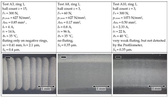
Figure 16.
Test rig #1: The smaller the ball count, the less or the later fluting occurs at the same apparent bearing current density Jb = 4.66 A/mm2.
4.7. Overview of the Results
The overview of the investigated parameters’ influence on the occurrence of fluting (Table 4) ranks the apparent bearing current density as the decisive factor, together with the moving lubricated roller elements as contacting partners to the raceway. Neither a stationary electrical contact, nor a rolling non-lubricated electrical contact will exhibit fluting [29].

Table 4.
Influencing parameters on fluting, : increase, : decrease.
5. Conclusions
An accelerated fluting generation due to DC bearing currents in axial ball bearings was investigated to find out the most prominent influencing parameters. Using axial bearings provides identical load parameters for all considered rolling elements in the bearing. Investigating single bearings in specially designed test rigs allowed us to vary the bearing operating parameters per bearing in a well-defined way. The non-linear voltage–current characteristic of the bearing at DC bearing currents was measured for different rotational speeds. The non-linearity was explained with Holm’s a-spot fritting contact theory. The DC bearing currents, due to the continuous power loss delivered to the bearing, lead to a fluting pattern much earlier than the inverter-induced HF bearing currents, so investigations were performed with DC currents. The acceleration of the generation of fluting by increasing the bearing current density was shown by increasing the bearing current amplitude, or by decreasing the Hertz’ian contact area by reducing the bearing force.
At DC, the bearing ring with negative polarity shows fluting first. An increased lubrication thickness leads to accelerated fluting generation, which can be achieved by increasing the speed or by decreasing the lubricant temperature. The type of lubricant, either a mineral-oil-based grease or a polyglycol oil, shows no significant impact on the test results.
The number of rolling elements is not the primary cause of a fluting pattern. In the axial bearing with an increased number of roller elements per bearing at the same bearing current density, fluting occurred earlier due to the increased number of contact partners, and electrical corrosion may happen. But even with a singular mechanical contact point, zebra-like fluting patterns are generated if the moving contact is lubricated. Hence, the assumption that the fluting pattern itself is primarily due to excited mechanical vibrations in combination with an electro-erosive current flow, as already indicated by Kohaut [13], is still valid. As a rule of thumb, a lubricated bearing at rotation with an apparent bearing current density per Hertz’ian area lower than 0.1 A/mm2, is safe from fluting. This limit is independent from the bearing, speed, mechanical load, and temperature. At standstill, much higher current densities are harmless for roller bearings.
Author Contributions
Conceptualization, O.S, R.C., M.W., A.B. and O.K.; investigation and experiment, O.S. and R.C.; software analysis, O.S.; writing—original draft preparation, O.S. and A.B.; writing—review and editing, O.S, A.B., R.C., M.W. and O.K.; All authors have read and agreed to the published version of the manuscript.
Funding
This research has financial support of Forschungsvereinigung Antriebstechnik e.V. and BMWK/AiF at project FVA 650 III and AiF with project No. 21488 N. The APC was funded by RPTU University of Kaiserslautern-Landau.
Data Availability Statement
Not applicable.
Acknowledgments
We are grateful to the institute “Produktentwicklung und Maschinenelemente” at TU Darmstadt for supporting us with the bearing surface measurements. We acknowledge the scientific support of Simon Graf at RPTU University of Kaiserslautern-Landau.
Conflicts of Interest
The authors declare no conflict of interest.
Correction Statement
Due to an error in article production, incorrect references were previously listed in the main text. There are two minor corrections to the references 22 and 29. This information has been updated and this change does not affect the scientific content of the article.
Nomenclature
| A | Area of contacting a-spots | n | Shaft rotational speed |
| AHz | Total Hertz’ian contact area per raceway | P | Equivalent dynamic load of the bearing |
| Momentary transversal ball acceleration | P | Electrical power | |
| Bearing width | pc,max | Maximum ball–raceway contact pressure | |
| Bearing voltage ratio | Rq1 | Surface profile roughness of a raceway, rms | |
| C | Dynamic load capacity of the bearing | Rq2 | Surface profile roughness of a ball, rms |
| C0 | Static load rating of the bearing | Rvar | Electrical variable resistance of test setup |
| Cb | Bearing capacitance | Sq | Surface profile roughness, rms |
| Cr-f | Rotor-to-frame capacitance | Momentary ball position | |
| Csw-f | Stator winding-to-frame capacitance | Amplitude of | |
| Csw-r | Stator winding-to-rotor capacitance | t | Time |
| D | Bearing outer diameter | tT | Test duration |
| d | Bearing inner diameter | Time-averaged bearing voltage | |
| Eb | Electric field strength in the lubricant | Time-averaged source voltage | |
| ED | Electrical breakdown field strength | Voltage | |
| F | Ball axial force | Momentary bearing voltage | |
| Fb | Bearing force | Common-mode motor terminal voltage | |
| f | Frequency | Momentary source voltage | |
| h | Central lubrication film thickness | wf | Fluting width |
| hf | Fluting height between peak and valley | Zb,DE | Drive-end bearing impedance |
| Minimum oil film thickness | Zb,NDE | Non-drive-end bearing impedance | |
| Ib | Time-averaged bearing current | ZPE | Stator-to-ground impedance |
| ib | Momentary bearing current | Zrg | Rotor-to-ground impedance |
| Bearing current amplitude | Number of the balls per bearing | ||
| iCM | Momentary common-mode current | Wave count of raceway fluting | |
| irg | Momentary rotor-to-ground current | ϑb | Average bearing temperature |
| isg | Momentary stator-to-ground current | λ | Lambda ratio of roughness h/σ |
| Jb | Apparent bearing current density | σ | Composite surface roughness of Rq1 and Rq2 , rms |
References
- Furtmann, A.; Poll, G. Electrical stress and parasitic currents in machine elements of drivetrains with voltage source inverters. Power Transm. Eng. 2018, 2018, 48–53. [Google Scholar]
- Schneider, V.; Behrendt, C.; Hoeltje, P.; Cornel, D.; Becker-Dombrowsky, F.M.; Puchtler, S.; Guitierrez Guzman, F.; Ponick, B.; Jacobs, G.; Kirchner, E. Electrical bearing damage, a problem in the nano- and macro-range. Lubricants 2022, 10, 194–214. [Google Scholar] [CrossRef]
- Graf, S.; Sauer, B. Surface mutation of the bearing raceway during electrical current passage in mixed friction operation. Bear. World J. 2020, 5, 137–147. [Google Scholar]
- Tischmacher, H. Systemanalysen zur Elektrischen Belastung von Wälzlagern bei Umrichtergespeisten Elektromotoren (System Analysis Regarding Electrical Stress in Rolling Element Bearings of Inverter-Fed Electrical Machines, in German). Ph.D. Thesis, Leibniz University Hannover, Hanover, Germany, 2017. [Google Scholar]
- Muetze, A. Thousands of hits: On inverter-induced bearing currents, related work, and the literature. E&I Elektrotechnik Informationstechnik 2011, 128, 382–388. [Google Scholar]
- Puchtler, S.; van der Kuip, J.; Kirchner, E. Analyzing ball bearing capacitance using single steel ball bearings. Tribol. Lett. 2023, 71, 38. [Google Scholar] [CrossRef]
- Scheuermann, S.; Hagemann, B.; Brodatzki, M.; Doppelbauer, M. Influence analysis on the bearings’ impedance behavior of inverter-fed motor drives. In Proceedings of the International Conference Elektrisch-Mechanische Antriebssysteme, Vienna, Austria, 8–9 November 2023; VDE: Hessen, Germany, 2023. [Google Scholar]
- Nagata, Y.; Glovnea, R. Dielectric properties of grease lubricants. Acta Tribol. 2010, 18, 34–41. [Google Scholar]
- Bechev, D.; Kiekbusch, T.; Sauer, B. Characterization of electrical lubricant properties for modelling of electrical drive systems with rolling bearings. Bear. World J. 2018, 3, 93–106. [Google Scholar]
- Raadnui, S.; Kleesuwan, S. Electrical pitting wear debris analysis of grease-lubricated rolling element bearings. Wear 2011, 271, 1707–1718. [Google Scholar] [CrossRef]
- Romanenko, A. Study of Inverter-Induced Bearing Damage Monitoring in Variable-Speed-Driven Motor Systems. Ph.D. Thesis, Lappeenranta University, Lappeenranta, Finland, 2017. [Google Scholar]
- Plazenet, T.; Boileau, T.; Caironi, C.C.; Nahid-Mobarakeh, B. Influencing parameters on discharge bearing currents in inverter-fed induction motors. IEEE Trans. Energy Convers. 2021, 36, 940–949. [Google Scholar] [CrossRef]
- Kohaut, A. Riffelbildung in Waelzlagern infolge elektrischer Korrosion (Fluting in roller bearings due to electrical erosion, in German). Z. Fuer Angew. Phys. 1948, 1, 197–211. [Google Scholar]
- Ortegel, F. Waelzlager in Elektromaschinen (Roller bearings in electrical machines, in German). In Proceedings of the Conference Waelzlager in Elektromaschinen und in der Buerotechnik, Schweinfurt, Germany; 1989. [Google Scholar]
- Harris, T.A. Rolling Bearing Analysis, 4th ed.; John Wiley & Sons: New York, NY, USA, 2001; ISBN 978-0-471-35457-4. [Google Scholar]
- Hamrock, B.J.; Dowson, D. Ball Bearing Lubrication, the Elastohydrodynamics of Elliptical Contacts; John Wiley and Sons: New York, NY, USA, 1981; ISBN 978-0-471-03553-4. [Google Scholar]
- Weicker, M.; Gemeinder, Y. Lagerimpedanz-Berechnungsprogramm V3-0, AxRiKuLa (Bearing Impedance Calculation Program), In-house calculator, Institute for Electrical Energy Conversion; TU Darmstadt: Darmstadt, Germany, 2018. [Google Scholar]
- Andreason, S. Stromdurchgang Durch Waelzlager (Passage of Electric Current through Rolling Bearings, in German). Die Kugellagerzeitschrift (SKF Co.) 1968, 153, 6–12. [Google Scholar]
- Holm, R. Electric Contacts, 4th ed.; Springer: Berlin/Heidelberg, Germany, 2013; ISBN 978-3-642-05708-3. [Google Scholar]
- Pittroff, H. Waelzlager im Elektrischen Stromkreis: Riffelbildung Infolge von Stromdurchgang (Roller Bearings in Electrical Circuits: Fluting Due to Current Flow, in German). Elektr. Bahnen 1968, 39, 54–61. [Google Scholar]
- Radnai, B.; Gemeinder, Y.; Sauer, B.; Binder, A. Schaedlicher Stromdurchgang (Harmful Bearing Currents, in German); Research Report Part I, Report no. 1127; FVA Forschungsvereinigung Antriebstechnik e.V.: Frankfurt, Germany, 2015. [Google Scholar]
- Safdarzadeh, O.; Binder, A.; Weicker, M. Measuring Electric Contact in an Axial Ball Bearing at DC Current Flow. IEEE Trans. Ind. Appl. 2023, 59, 3341–3352. [Google Scholar]
- Kuechler, A. High Voltage Engineering: Fundamentals-Technology-Applications; Springer: Berlin/Heidelberg, Germany, 2017; ISBN 978-3-642-11992-7. [Google Scholar]
- Safdarzadeh, O.; Weicker, M.; Binder, A. Transient Thermal Analysis of the Contact in Bearings Exposed to Electrical Currents. In Proceedings of the 4th International FVA-Conference: “The Expert Forum for Bearings”, Wuerzburg, Germany, 5–6 July 2022; pp. 24–32. [Google Scholar]
- Prashad, H. Tribology in Electrical Enviroments; Elsevier: Hyderabad, India, 2005; ISBN 978-0-444-51880-4. [Google Scholar]
- ISO 25178; Geometrical Product Specifications (GPS)—Surface Texture: Areal. ISO: Geneva, Switzerland, 2016.
- ISO 16610-61; Geometrical Product Specification (GPS)—Filtration—Part 61: Linear Areal Filters—Gaussian Filters. ISO: Geneva, Switzerland, 2015.
- Mikami, H.; Kawamura, T. Influence of Electrical Current on Bearing Flaking Life; Technical Paper no. 2007-01-0113; SAE World Congress & Exhibition: Detroit, MI, USA, 2007. [Google Scholar]
- Capan, R.; Safdarzadeh, O.; Graf, S.; Weicker, M.; Sauer, B.; Binder, A.; Koch, O. Schädlicher Stromdurchgang (Harmful Bearing Currents), in German; Research Report, Part III; FVA Forschungsvereinigung Antriebstechnik e.V.: Frankfurt, Germany, 2023. [Google Scholar]
Disclaimer/Publisher’s Note: The statements, opinions and data contained in all publications are solely those of the individual author(s) and contributor(s) and not of MDPI and/or the editor(s). MDPI and/or the editor(s) disclaim responsibility for any injury to people or property resulting from any ideas, methods, instructions or products referred to in the content. |
© 2023 by the authors. Licensee MDPI, Basel, Switzerland. This article is an open access article distributed under the terms and conditions of the Creative Commons Attribution (CC BY) license (https://creativecommons.org/licenses/by/4.0/).