Thermal Preload for Predicting Performance Change Due to Pad Thermal Deformation of Tilting Pad Journal Bearing


Abstract
1. Introduction
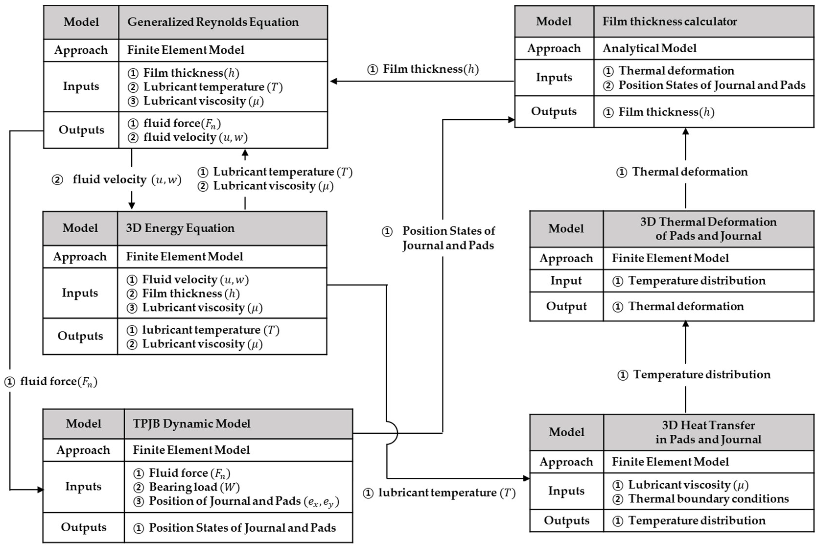
2. Numerical Models
2.1. Lubrication Model
- (a)
- Lubricant flow is full laminar.
- (b)
- Shaft curvature effect is neglected.
- (c)
- In the film thickness direction, the pressure is assumed to be constant.
- (d)
- Fluid inertia is not considered.
- (e)
- Fluid density is kept to be constant.
- (f)
- Incompressible Newtonian fluid.
- (g)
- At the slid and fluid interface, there is no slip.
- (h)
- Reynolds cavitation boundary condition.
2.2. Heat Transfer and Thermal Deformation Model
2.3. Algorithm
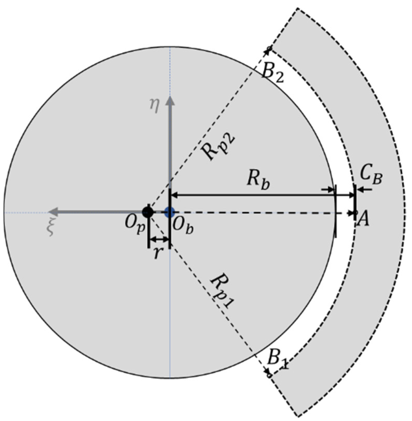
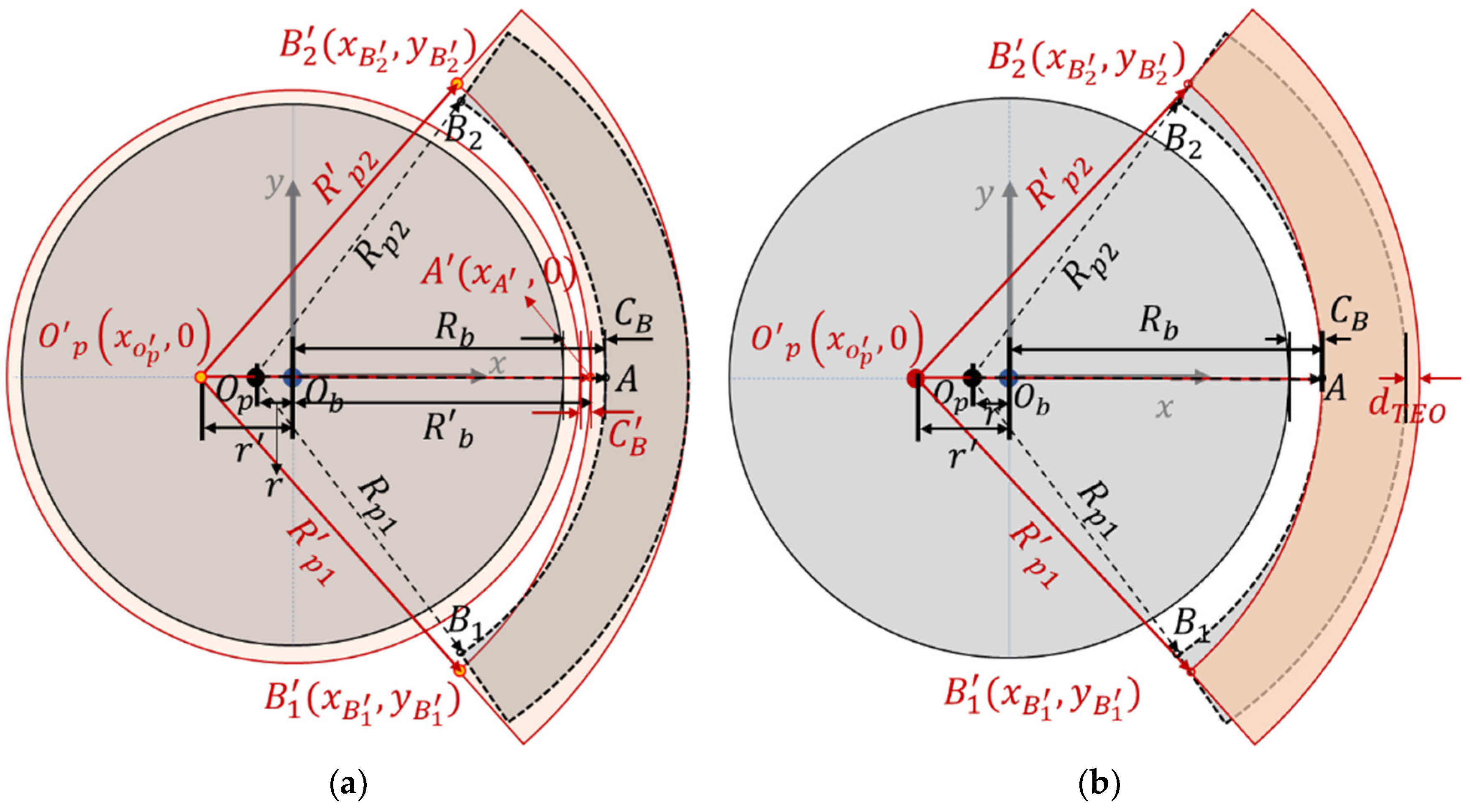
2.4. Suggestion of Thermal Preload
2.4.1. Preload
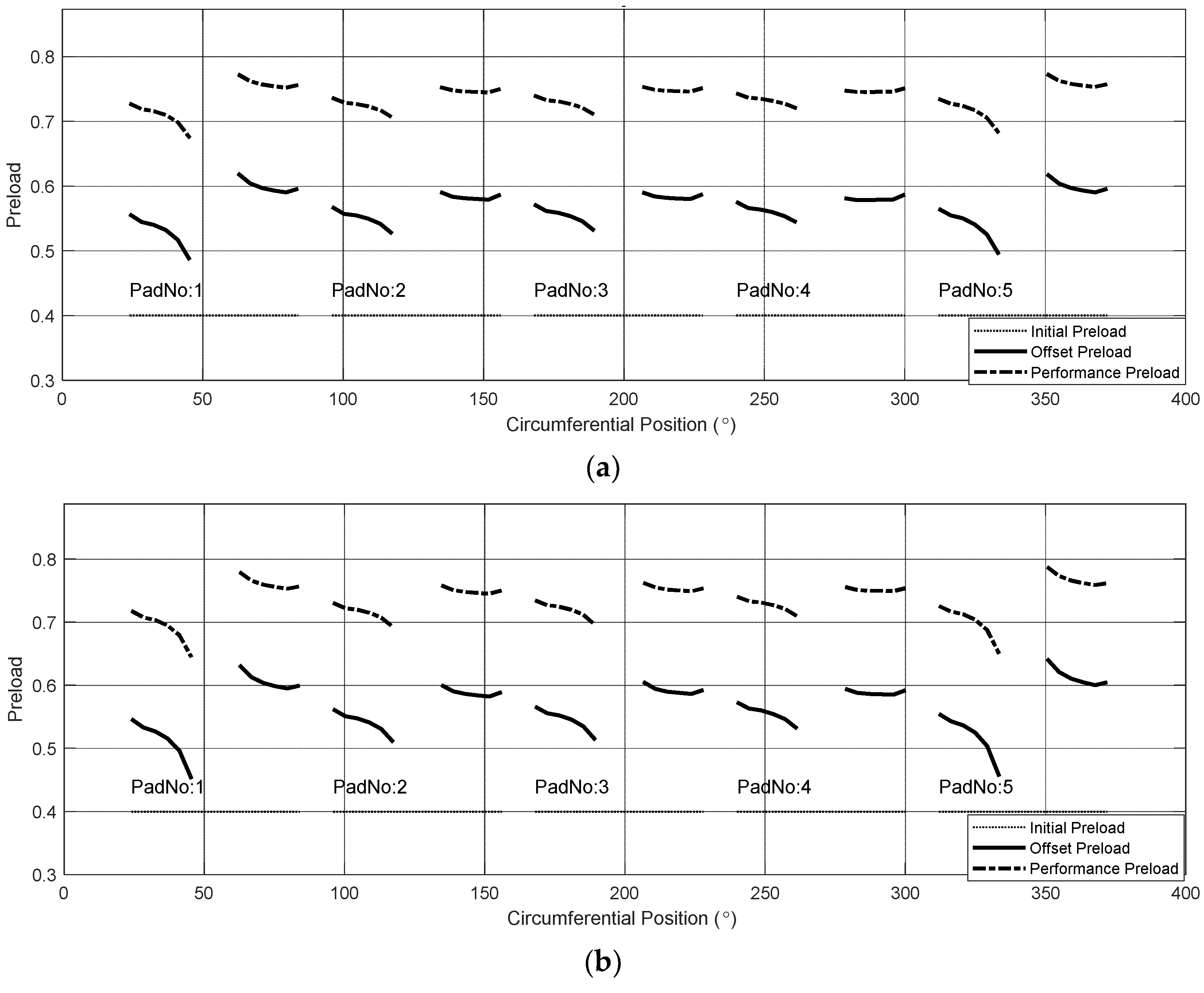
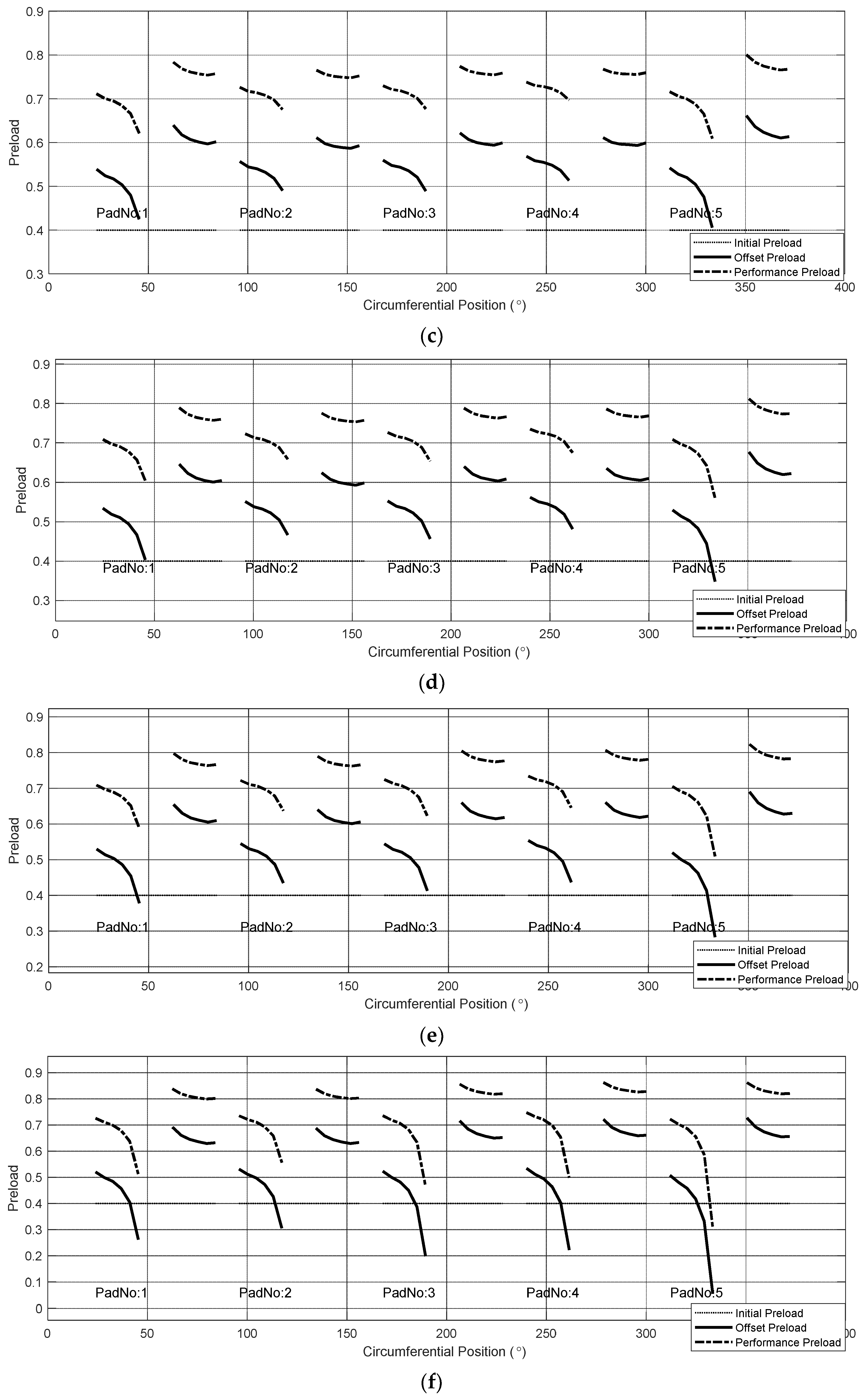
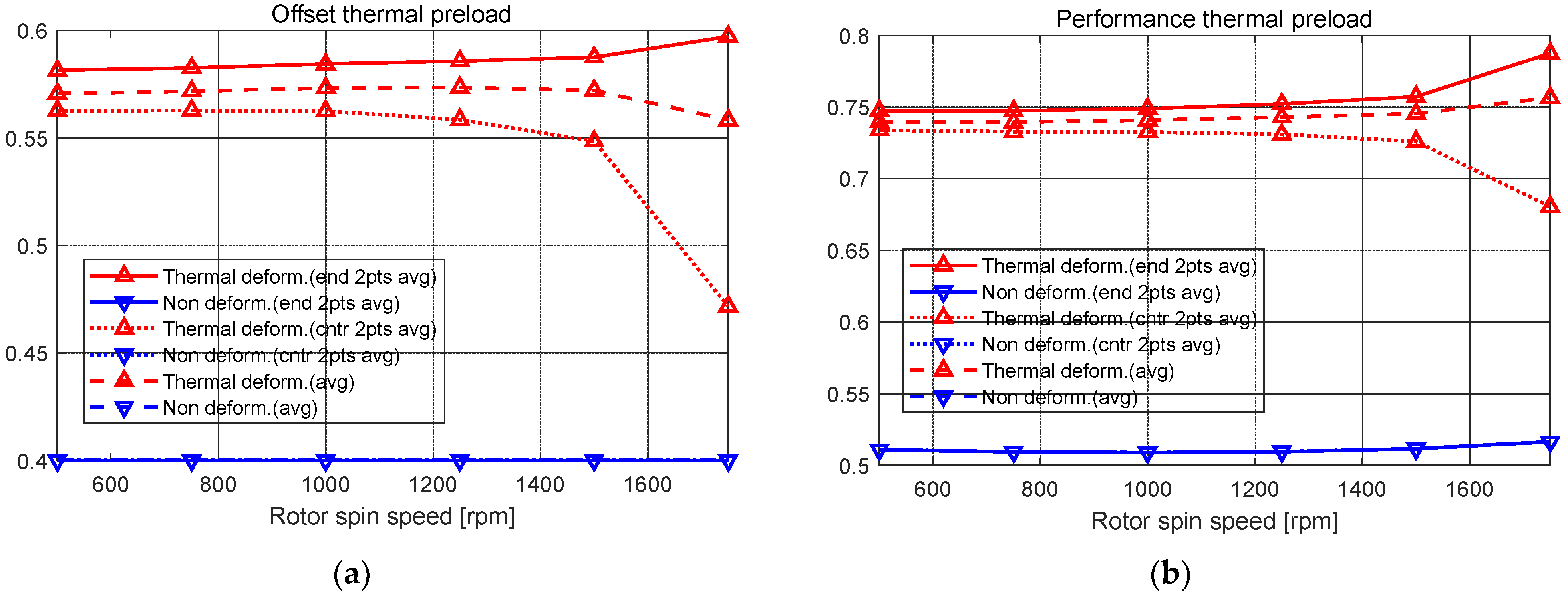
2.4.2. Performance Thermal Preload and Offset Thermal Preload
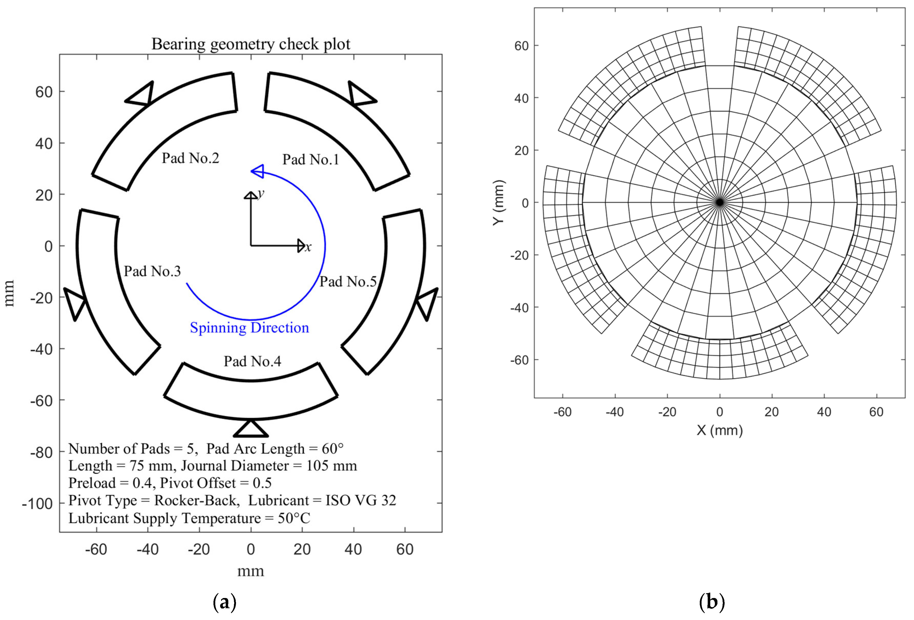
3. Numerical Results and Discussions
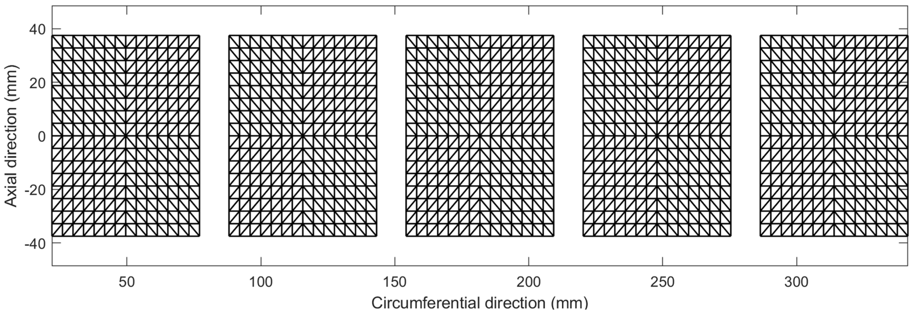
3.1. Simulation Model
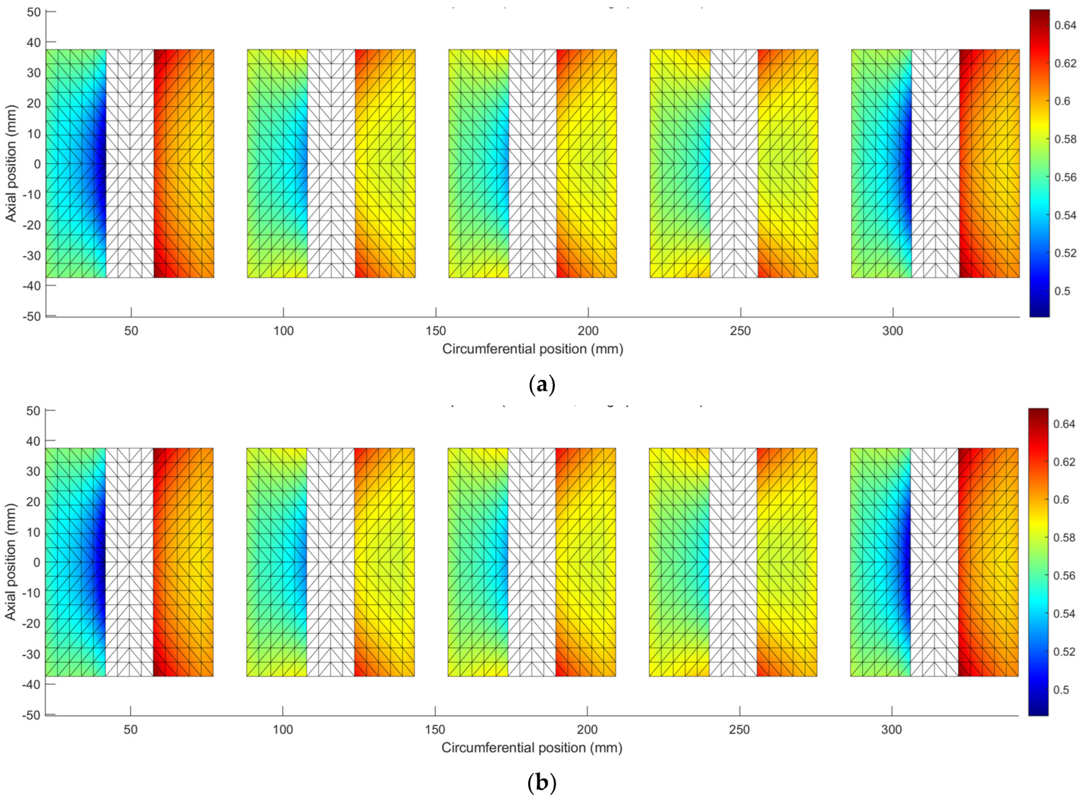
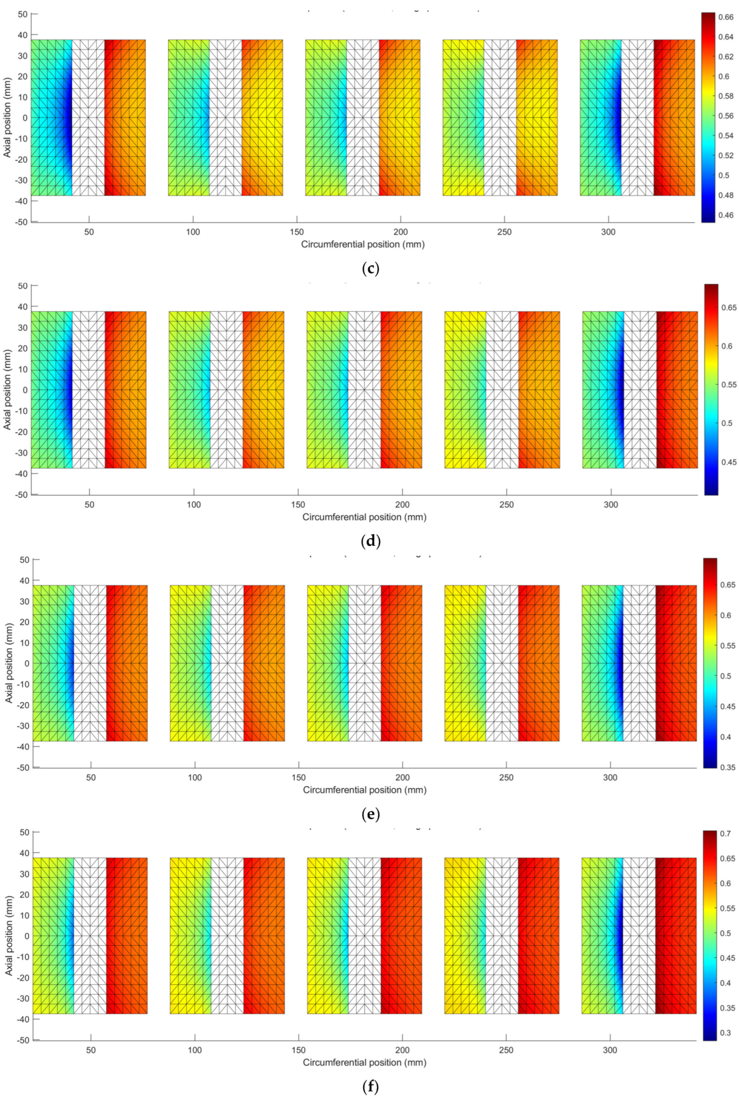
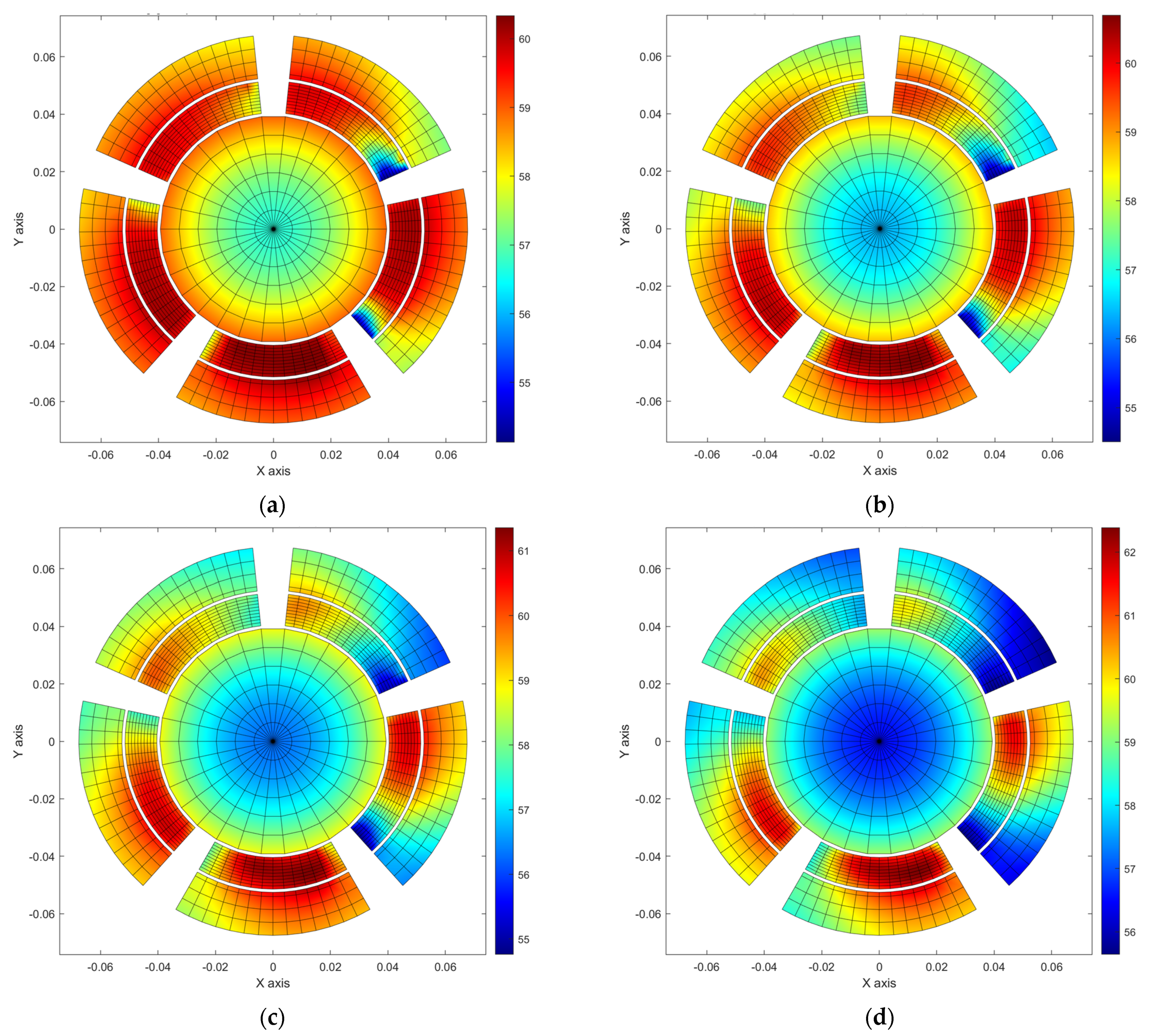
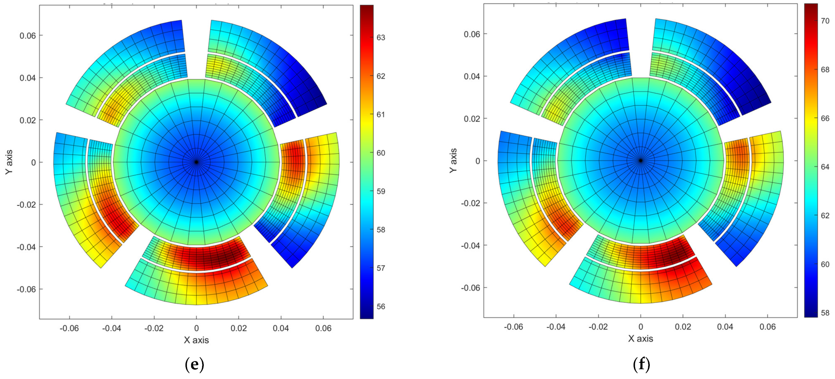
3.2. Pad Thermal Deformation Shape and Offset Thermal Preload
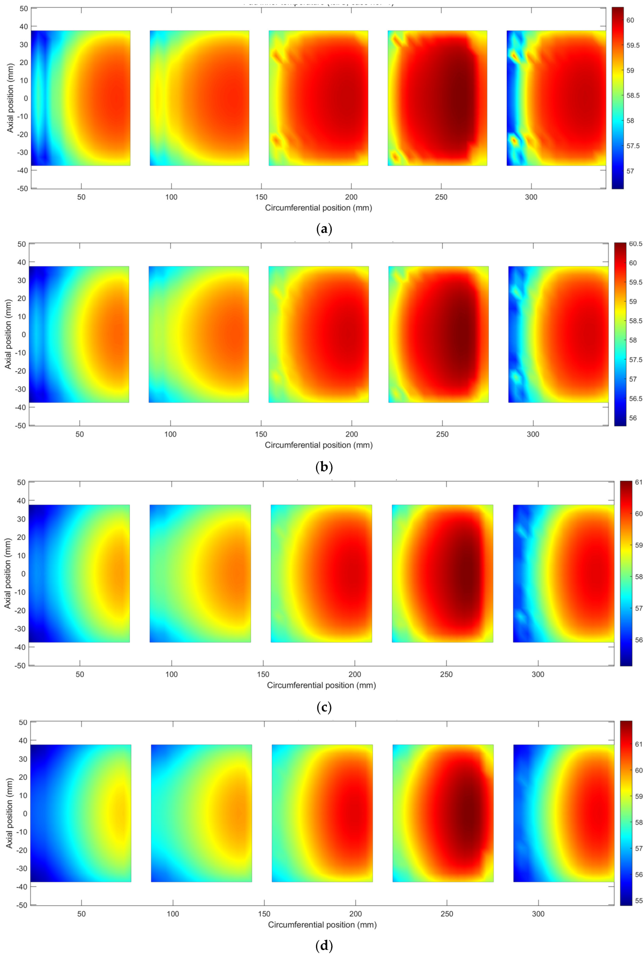
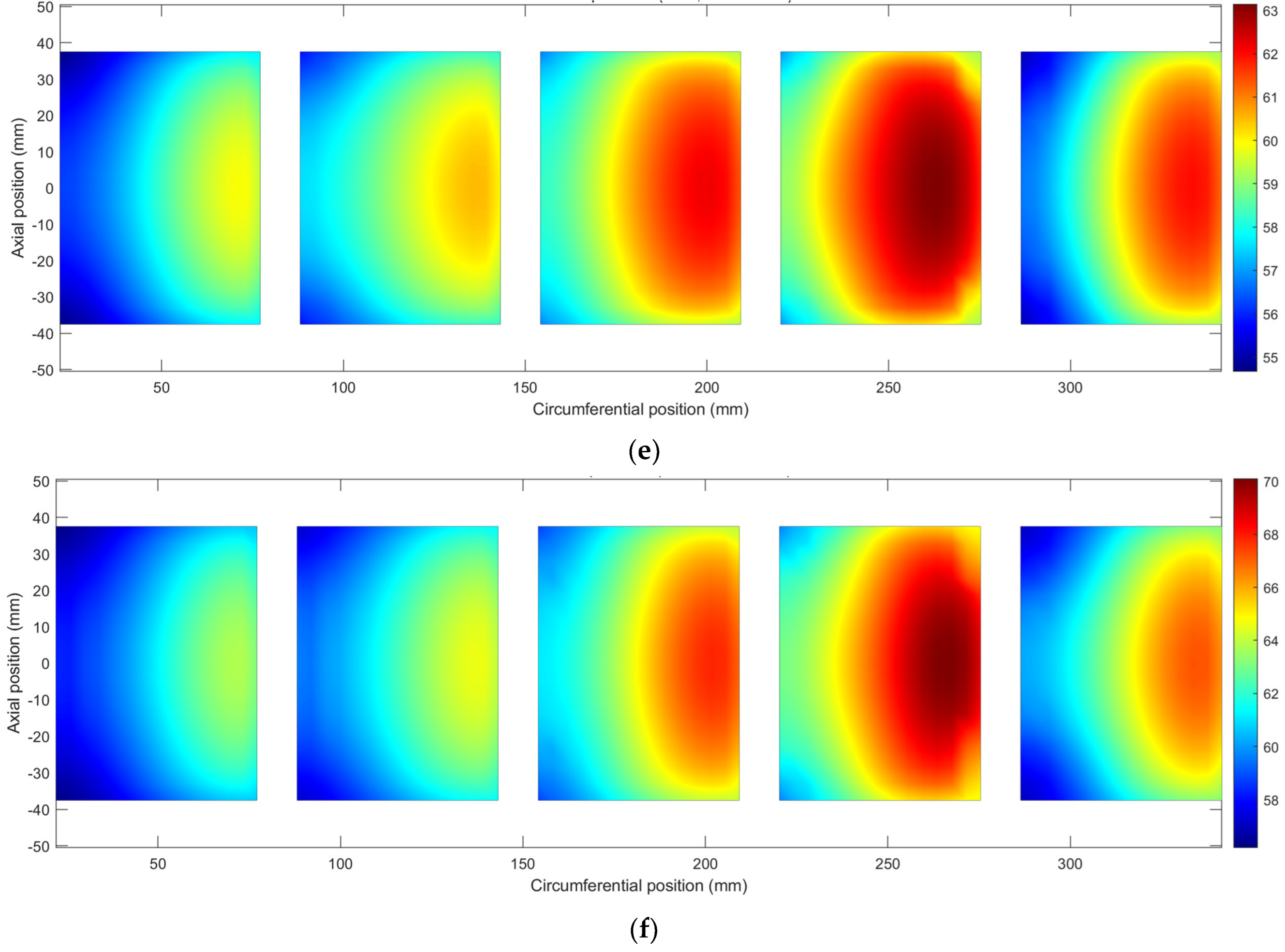
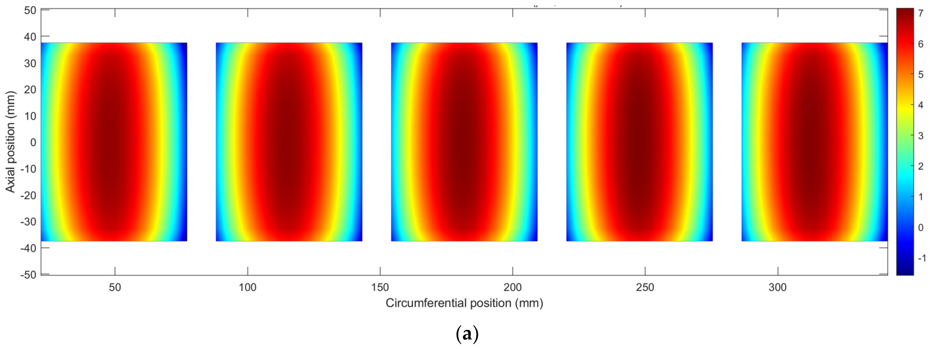
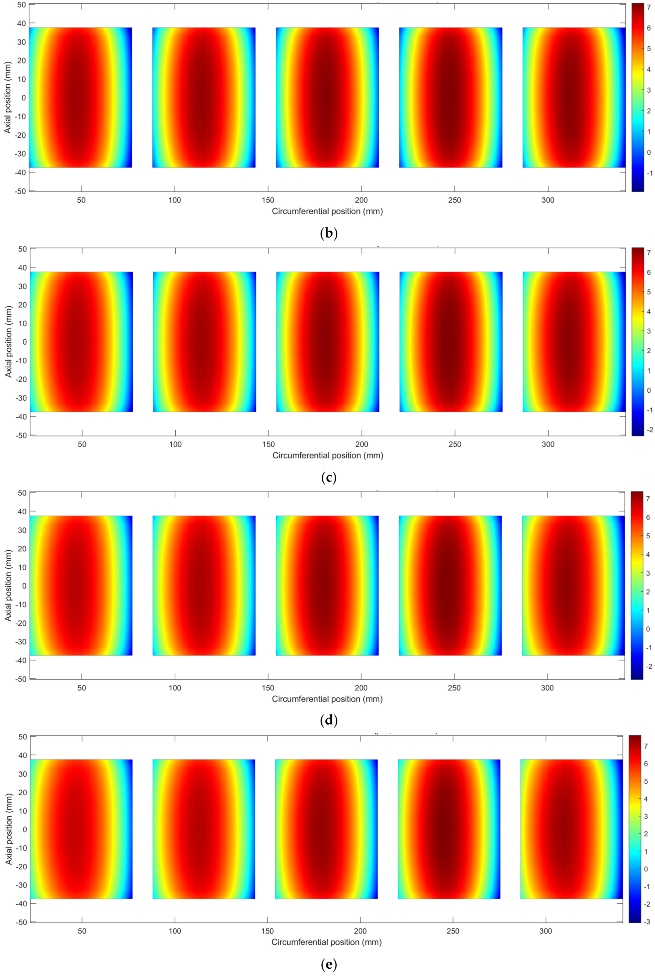
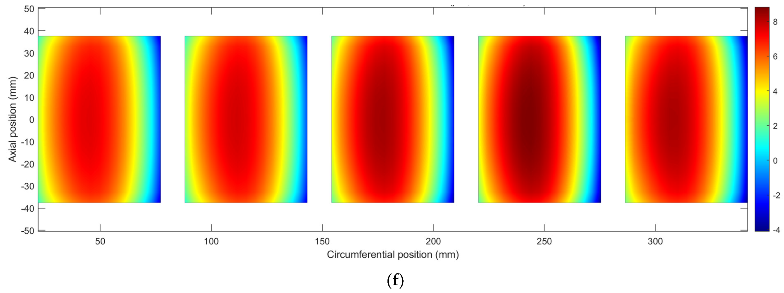
3.3. Thermal Deformation Effect
4. Conclusions
- (a)
- The concept of the offset thermal preload was suggested to quantify the thermal deformation shape of the bearing pad.
- (b)
- The concept of the performance thermal preload was suggested to quantify the thermal deformation of the bearing structure and the resulting bearing performance change.
- (c)
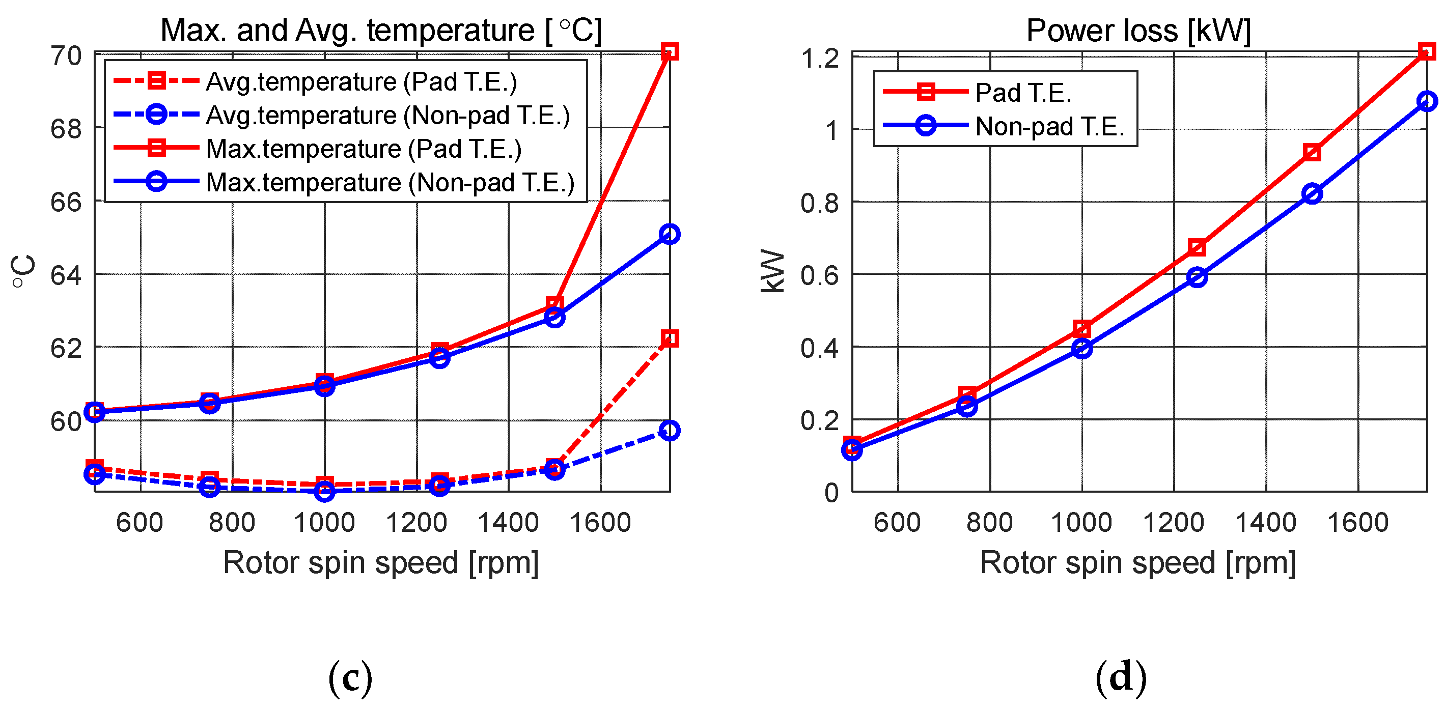
- It was found that as the temperature of the bearing increases, the performance change of the bearing due to the thermal deformation of the pad also increases.
- (a)
- The original shape of the bearing pad does not maintain its original circular shape due to the thermal deformation.
- (b)
- The ‘end 2pts avg’ preload increases due to the pad thermal deformation, which decreases the direct damping terms, while the ‘cntr 2pts avg’ decreases due to the pad thermal deformation, which increases the direct stiffness terms.
- (c)
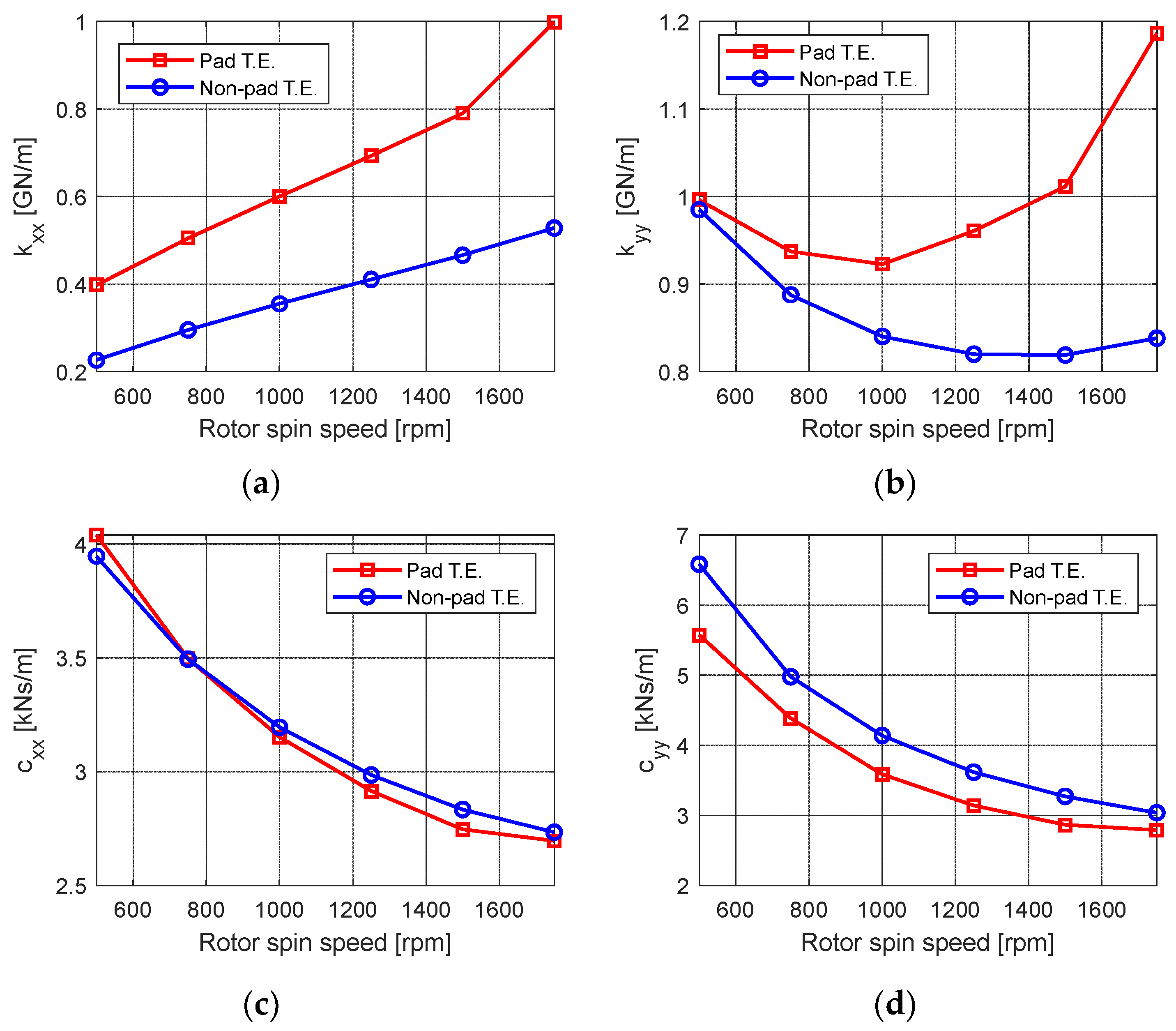
- The model neglecting the pad thermal deformation showed a stiffness coefficient up 92% higher than that of the model not considering the thermal deformation.
- (d)
- When the pad thermal deformation was considered, the damping coefficient was up to 10% higher than when it was not taken into account; however, the effect seems insignificant compared to the increase in the stiffness coefficient.
Author Contributions
Funding
Data Availability Statement
Conflicts of Interest
Nomenclature
| Pressure | |
| Lubricant velocity | |
| Lubricant velocity in x direction | |
| Lubricant velocity in z direction | |
| Density | |
| Heat capacity | |
| Time | |
| Heat conductivity | |
| x position in cartesian coordinate | |
| y position in cartesian coordinate | |
| z position in cartesian coordinate | |
| Radial position | |
| Circumferential position | |
| Viscosity | |
| Reference viscosity for lubricant viscosity change due to temperature | |
| Temperature | |
| Reference temperature for lubricant viscosity change due to temperature | |
| Pad clearance | |
| Bearing clearance | |
| Pad radius | |
| Bearing radius | |
| Shaft radius | |
| Journal radius | |
| Journal position in x direction | |
| Journal position in y direction | |
| Pivot circumferential position | |
| Pad tilt angle | |
| Preload | |
| Film thickness | |
| Film thickness changes due to journal thermal deformation | |
| Film thickness changes due to pad thermal deformation |
References
- Chen, W.J. Practical Rotordynamics and Fluid Film Bearing Design; Eigen Technologies, Inc.: Davidson, NC, USA, 2015. [Google Scholar]
- Someya, T.; Mitsui, J.; Esaki, J.; Saito, S.; Kanemitsu, Y.; Iwatsubo, T.; Kanki, H. Journal-Bearing Databook; Springer Science & Business Media: Berlin/Heidelberg, Germany, 2013. [Google Scholar]
- Suh, J.; Palazzolo, A. Three-Dimensional Dynamic Model of TEHD Tilting-Pad Journal Bearing—Part I: Theoretical Modeling. J. Tribol. 2015, 137, 041703. [Google Scholar] [CrossRef]
- Suh, J.; Palazzolo, A. Three-Dimensional Dynamic Model of TEHD Tilting-Pad Journal Bearing—Part II: Parametric Studies. J. Tribol. 2015, 137, 041704. [Google Scholar] [CrossRef]
- Dowson, D. A generalized Reynolds equation for fluid-film lubrication. Int. J. Mech. Sci. 1962, 4, 159–170. [Google Scholar] [CrossRef]
- Dowson, D.; Hudson, J.D.; Hunter, B.; March, C.N. Paper 3: An Experimental Investigation of the Thermal Equilibrium of Steadily Loaded Journal Bearings. Proc. Inst. Mech. Eng. Conf. Proc. 1966, 181, 70–80. [Google Scholar] [CrossRef]
- Tieu, A.K. Oil-Film Temperature Distribution in an Infinitely wide Slider Bearing: An Application of the Finite-Element Method. J. Mech. Eng. Sci. 1973, 15, 311–320. [Google Scholar] [CrossRef]
- Safar, Z.S. Thermohydrodynamic Analysis for Laminar Flow Journal Bearing. J. Lubr. Technol. 1978, 100, 510–512. [Google Scholar] [CrossRef]
- Suganami, T.; Szeri, A.Z. A Thermohydrodynamic Analysis of Journal Bearings. J. Lubr. Technol. 1979, 101, 21–27. [Google Scholar] [CrossRef]
- Ettles, C.M.M. The Analysis and Performance of Pivoted Pad Journal Bearings Considering Thermal and Elastic Effects. J. Lubr. Technol. 1980, 102, 182–191. [Google Scholar] [CrossRef]
- Smith, R.N.; Tichy, J.A. An Analytical Solution for the Thermal Characteristics of Journal Bearings. J. Lubr. Technol. 1981, 103, 443–452. [Google Scholar] [CrossRef]
- Nicholas, J.C.; Kirk, R.G. Four Pad Tilting Pad Bearing Design and Application for Multistage Axial Compressors. J. Lubr. Technol. 1982, 104, 523–529. [Google Scholar] [CrossRef]
- Knight, J.D.; Barrett, L.E. Analysis of Axially Grooved Journal Bearings with Heat Transfer Effects. ASLE Trans. 1987, 30, 316–323. [Google Scholar] [CrossRef]
- Lund, J.W.; Hansen, P.K. An Approximate Analysis of the Temperature Conditions in a Journal Bearing. Part I: Theory. J. Tribol. 1984, 106, 228–236. [Google Scholar] [CrossRef]
- Lund, J.W.; Tonnesen, J. An Approximate Analysis of the Temperature Conditions in a Journal Bearing. Part II: Application. J. Tribol. 1984, 106, 237–244. [Google Scholar] [CrossRef]
- Khonsari, M.M.; Beaman, J.J. Thermohydrodynamic Analysis of Laminar Incompressible Journal Bearings. A S L E Trans. 1986, 29, 141–150. [Google Scholar] [CrossRef]
- Kacou, A.; Rajagopal, K.R.; Szeri, A.Z. A Thermohydrodynamic Analysis of Journal Bearings Lubricated by a Non-Newtonian Fluid. J. Tribol. 1988, 110, 414–420. [Google Scholar] [CrossRef]
- Knight, J.D. Prediction of Temperatures in Tilting Pad Journal Bearings. Tribol. Trans. 1990, 33, 185–192. [Google Scholar] [CrossRef]
- Taniguchi, S.; Makino, T.; Takeshita, K.; Ichimura, T. A Thermohydrodynamic Analysis of Large Tilting-Pad Journal Bearing in Laminar and Turbulent Flow Regimes with Mixing. J. Tribol. 1990, 112, 542–548. [Google Scholar] [CrossRef]
- Fillon, M.; Bligoud, J.-C.; Frene, J. Experimental Study of Tilting-Pad Journal Bearings—Comparison with Theoretical Thermoelastohydrodynamic Results. J. Tribol. 1992, 114, 579–587. [Google Scholar] [CrossRef]
- Simmons, J.E.L.; Dixon, S.J. Effect of Load Direction, Preload, Clearance Ratio, and Oil Flow on the Perfonmance of a 200 mm Journal Pad Bearing. Tribol. Trans. 1994, 37, 227–236. [Google Scholar] [CrossRef]
- Kim, J.; Palazzolo, A.B.; Gadangi, R.K. TEHD Analysis for Tilting-Pad Journal Bearings Using Upwind Finite Element Method. Tribol. Trans. 1994, 37, 771–783. [Google Scholar] [CrossRef]
- Kim, J.; Palazzolo, A.; Gadangi, R. Dynamic Characteristics of TEHD Tilt Pad Journal Bearing Simulation Including Multiple Mode Pad Flexibility Model. J. Vib. Acoust. 1995, 117, 123–135. [Google Scholar] [CrossRef]
- Gadangi, R.K.; Palazzolo, A.B. Transient Analysis of Tilt Pad Journal Bearings Including Effects of Pad Flexibility and Fluid Film Temperature. J. Tribol. 1995, 117, 302–307. [Google Scholar] [CrossRef]
- Gadangi, R.K.; Palazzolo, A.B.; Kim, J. Transient Analysis of Plain and Tilt Pad Journal Bearings Including Fluid Film Temperature Effects. J. Tribol. 1996, 118, 423–430. [Google Scholar] [CrossRef]
- Monmousseau, P.; Fillon, M.; Fre^ne, J. Transient Thermoelastohydrodynamic Study of Tilting-Pad Journal Bearings—Comparison Between Experimental Data and Theoretical Results. J. Tribol. 1997, 119, 401–407. [Google Scholar] [CrossRef]
- Monmousseau, P.; Fillon, M. Frequency Effects on the TEHD Behavior of a Tilting-Pad Journal Bearing Under Dynamic Loading. J. Tribol. 1999, 121, 321–326. [Google Scholar] [CrossRef]
- Chang, Q.; Yang, P.; Meng, Y.; Wen, S. Thermoelastohydrodynamic analysis of the static performance of tilting-pad journal bearings with the Newton–Raphson method. Tribol. Int. 2002, 35, 225–234. [Google Scholar] [CrossRef]
- Sim, K.; Kim, D. Thermohydrodynamic Analysis of Compliant Flexure Pivot Tilting Pad Gas Bearings. J. Eng. Gas Turbines Power 2008, 130, 032502. [Google Scholar] [CrossRef]
- Bang, K.-B.; Kim, J.-H.; Cho, Y.-J. Comparison of power loss and pad temperature for leading edge groove tilting pad journal bearings and conventional tilting pad journal bearings. Tribol. Int. 2009, 43, 1287–1293. [Google Scholar] [CrossRef]
- Tschoepe, D.P.; Childs, D.W. Measurements Versus Predictions for the Static and Dynamic Characteristics of a Four-Pad, Rocker-Pivot, Tilting-Pad Journal Bearing. J. Eng. Gas Turbines Power 2014, 136, 052501. [Google Scholar] [CrossRef]
- Zhang, F.; Ouyang, W.; Hong, H.; Guan, Y.; Yuan, X.; Dong, G. Experimental study on pad temperature and film thickness of tilting-pad journal bearings with an elastic-pivot pad. Tribol. Int. 2015, 88, 228–235. [Google Scholar] [CrossRef]
- Alakhramsing, S.; Van Ostayen, R.; Eling, R. Thermo-Hydrodynamic Analysis of a Plain Journal Bearing on the Basis of a New Mass Conserving Cavitation Algorithm. Lubricants 2015, 3, 256–280. [Google Scholar] [CrossRef]
- Mo, J.; Gu, C.; Pan, X.; Zheng, S.; Ying, G. A Thermohydrodynamic Analysis of the Self-Lubricating Bearings Applied in Gear Pumps Using Computational Fluid Dynamics Method. J. Tribol. 2017, 140. [Google Scholar] [CrossRef]
- Nichols, B.R.; Fittro, R.L.; Goyne, C.P. Steady-State Tilting-Pad Bearing Performance Under Reduced Oil Supply Flow Rates. J. Tribol. 2018, 140. [Google Scholar] [CrossRef]
- Arihara, H.; Kameyama, Y.; Baba, Y.; Andrés, L.S. A Thermoelastohydrodynamic Analysis for the Static Performance of High-Speed—Heavy Load Tilting-Pad Journal Bearing Operating in the Turbulent Flow Regime and Comparisons to Test Data. J. Eng. Gas Turbines Power 2018, 141. [Google Scholar] [CrossRef]
- Yang, J.; Palazzolo, A. Three-Dimensional Thermo-Elasto-Hydrodynamic Computational Fluid Dynamics Model of a Tilting Pad Journal Bearing—Part I: Static Response. J. Tribol. 2019, 141, 061702. [Google Scholar] [CrossRef]
- Yang, J.; Palazzolo, A. Three-Dimensional Thermo-Elasto-Hydrodynamic Computational Fluid Dynamics Model of a Tilting Pad Journal Bearing—Part II: Dynamic Response. J. Tribol. 2019, 141, 061703. [Google Scholar] [CrossRef]
- Chatterton, S.; Pennacchi, P.; Vania, A.; Dang, P.V. Cooled Pads for Tilting-Pad Journal Bearings. Lubricants 2019, 7, 92. [Google Scholar] [CrossRef]
- Suh, J.; Kim, C.; Han, J.-H. Effect of Thermal Boundary Condition on Tilting Pad Journal Bearing Behavior. Appl. Sci. 2020, 10, 7540. [Google Scholar] [CrossRef]
- Jeung, S.-H.; Suh, J.; Yoon, H.S. Performance of Tilting Pad Journal Bearings with the Same Sommerfeld Number. Appl. Sci. 2020, 10, 3529. [Google Scholar] [CrossRef]
- Bagiński, P.; Żywica, G.; Roemer, J.; Zdziebko, P.; Martowicz, A. Experimental Study of the Influence of Rotor Dynamics on the Temperature Distribution of a Gas Foil Bearing. Appl. Sci. 2022, 12, 9274. [Google Scholar] [CrossRef]
- Guo, H.; Bao, J.; Zhang, S.; Shi, M. Experimental and Numerical Study on Mixed Lubrication Performance of Journal Bearing Considering Misalignment and Thermal Effect. Lubricants 2022, 10, 262. [Google Scholar] [CrossRef]
- Gomiciaga, R.; Keogh, P.S. Orbit Induced Journal Temperature Variation in Hydrodynamic Bearings. J. Tribol. 1999, 121, 77–84. [Google Scholar] [CrossRef]


| Lubricant | |
|---|---|
| Viscosity coefficient (Pa·s) | 0.0297 |
| Viscosity at 40 °C (N·s/m2) | 0.0365 |
| Heat conductivity (W/(mK)) | 0.136 |
| Heat capacity (J/kg·°C) | 1886 |
| Density (kg/m3) | 877 |
| Journal | |
| Young’s Modulus (Pa) | 2.05 × 10¹¹ |
| Poisson’s ratio | 0.3 |
| Reference temperature for thermal expansion (°C) | 25 |
| Thermal expansion coefficient (1/°C) | 1.22 × 10⁻⁵ |
| Heat conductivity (W/(m °C)) | 42.6 |
| Heat capacity (J/(kg °C)) | 453.6 |
| Pad | |
| Young’s Modulus (Pa) | 2.00 × 10¹¹ |
| Poisson’s ratio | 0.3 |
| Reference temperature for thermal expansion (°C) | 25 |
| Thermal expansion coefficient (1/°C) | 1.21 × 10⁻⁵ |
| Heat conductivity (W/(m °C)) | 51.9 |
| Heat capacity (J/(kg °C) | 453.6 |
| Babbitt | |
| Young’s Modulus (Pa) | 5.3 × 10¹⁰ |
| Poisson’s ratio | 0.3 |
| Reference temperature for thermal expansion (°C) | 25 |
| Thermal expansion coefficient (1/°C) | 2.1 × 10⁻⁵ |
| Heat conductivity (W/(m °C)) | 55 |
| Heat capacity (J/(kg °C) | 230 |
| Housing | |
| Young’s Modulus (Pa) | 1.86 × 10¹¹ |
| Poisson’s ratio | 0.3 |
| Running Conditions | |
|---|---|
| Sommerfeld number | 0.162 |
| Rotor spin speed (rpm) | 500~1250 |
| Load direction | LOP |
| Ambient temperature (°C) | 30 |
| Convection coefficient (W°C/m2) | 100 |
| Lubricant supply temperature (°C) | 50 |
| Mixing coefficient at oil groove | 0.8 |
| Bearing configurations | |
| Number of pads | 5 |
| Pad arc length (°) | 60 |
| Offset | 0.5 |
| Preload | 0.4 |
| Unit load (MPa) | 1.41 |
| Bearing load (N) | 11,070 |
| Journal diameter (mm) | 105 |
| Pad thickness (mm) | 15 |
| Babbitt thickness (mm) | 1.5 |
| Pad clearance (mm) | 0.096 |
| Pad length (mm) | 75 |
| Pivot type | Rocker-back |
| Dp (mm) | 114 |
| Dh (mm) | 135 |
Disclaimer/Publisher’s Note: The statements, opinions and data contained in all publications are solely those of the individual author(s) and contributor(s) and not of MDPI and/or the editor(s). MDPI and/or the editor(s) disclaim responsibility for any injury to people or property resulting from any ideas, methods, instructions or products referred to in the content. |
© 2022 by the authors. Licensee MDPI, Basel, Switzerland. This article is an open access article distributed under the terms and conditions of the Creative Commons Attribution (CC BY) license (https://creativecommons.org/licenses/by/4.0/).
Share and Cite
Chun, Y.-D.; Lee, J.; Lee, J.; Suh, J. Thermal Preload for Predicting Performance Change Due to Pad Thermal Deformation of Tilting Pad Journal Bearing. Lubricants 2023, 11, 3. https://doi.org/10.3390/lubricants11010003
Chun Y-D, Lee J, Lee J, Suh J. Thermal Preload for Predicting Performance Change Due to Pad Thermal Deformation of Tilting Pad Journal Bearing. Lubricants. 2023; 11(1):3. https://doi.org/10.3390/lubricants11010003
Chicago/Turabian StyleChun, Yon-Do, Jiheon Lee, Jiyoung Lee, and Junho Suh. 2023. "Thermal Preload for Predicting Performance Change Due to Pad Thermal Deformation of Tilting Pad Journal Bearing" Lubricants 11, no. 1: 3. https://doi.org/10.3390/lubricants11010003
APA StyleChun, Y.-D., Lee, J., Lee, J., & Suh, J. (2023). Thermal Preload for Predicting Performance Change Due to Pad Thermal Deformation of Tilting Pad Journal Bearing. Lubricants, 11(1), 3. https://doi.org/10.3390/lubricants11010003